Pitney Bowes Inc. has entered into a multi-year partnership with INRIX, Inc., provider of traffic information and driver services, to deliver advanced location intelligence solutions through the company’s traffic intelligence platform.
By integrating location capabilities with traffic analysis, INRIX and Pitney Bowes will enhance the driving experience of today’s connected drivers, the companies said. By delivering this information through INRIX’s mobile app, users are empowered to make better location-based decisions in real-time.
“Pitney Bowes’ location intelligence solutions can add compelling new capabilities to the existing products of mobile-oriented companies such as INRIX,” said James Buckley, Senior Vice President and General Manager, Location Intelligence, Pitney Bowes. “Our products help unearth non-obvious relationships between specific locations to improve the customer experience and drive loyalty.”
INRIX has designed a leading traffic intelligence platform that uses smart data and advanced analytics to solve transportation issues worldwide. The company uses a unique approach called “smart crowd-sourcing” that analyzes real-time traffic speed and incident data from a wide variety of public and private traffic sources ranging from road sensors and up-to-the-minute traffic speeds and community reports crowd-sourced from millions of vehicles and mobile devices throughout the day. Whether through an in-car or smartphone navigation application, a local newscast or the company’s INRIX Traffic app, INRIX offers up-to-the-minute traffic information and other driver services to help more than 150 million drivers save time, fuel and money.
Pitney Bowes Location Intelligence solutions merge organizational data with location data to provide users with the capability to make more informed decisions. For INRIX, this technology compiles and correlates addresses with coordinates from a mobile device to establish real-time location or a desired destination. Combining that with other data such as specific traffic flow, demographics and behavior patterns, users can uncover key points of interest by accessing Pitney Bowes advanced location search. For example, if a consumer is planning to visit a popular department store in a specific region, the technology makes it possible to suggest a relevant restaurant recommendation for lunch, based on the data that is collected about user preferences, convenience, proximity and projected traffic patterns.
“INRIX had a number of compelling reasons to partner with Pitney Bowes,” said Scott Sedlik, Vice President, Product Planning and Market Development for INRIX. “Our customers are looking to make real-time decisions using location data, and Pitney Bowes has the most comprehensive suite of offerings to fulfill that need. Other key reasons for teaming include a strong customer focus and alignment with our own strategic goals and approach.”
PeopleNet, a Trimble company and provider of fleet mobility technology that optimizes performance and decision-making management, has launched a mapping and navigation solution for its Energy Services suite, serving U.S. fleets in the upstream and midstream sectors.
“Our Energy Services suite capitalizes on our proven fleet mobility solutions that increase efficiency, safety and compliance for all oilfield service segments, including producers, oilfield construction and well service companies, as well as haulers of fluid and crude oil. In addition, we’re leveraging our parent and sister companies’ industry-standard lone-worker, mapping and navigation technologies to fast-track development of new services to continue improving operations for Energy Services fleets,” said David Buhl, leader of PeopleNet’s dedicated Energy Services Division.
PeopleNet’s new Energy Services mapping and navigation solutions are based on exclusive, detailed maps of private and leased oilfield roads that facilitate vehicle navigation to and from well sites, coordination of disparate workforces to promote efficiency, location monitoring of equipment to ensure vehicles are on the correct route for least-cost routing. The Oil and Gas Map Portal is a web-based application used by back-office dispatch personnel to manage the navigation needs of vehicles and includes reporting, dashboards, and scorecards that help manage compliance with producer-landowner road-usage agreements.
CoPilot Oil and Gas Navigation is an in-cab application that uses oil and gas field mapping for providing turn-by-turn directions to the driver to enable on-time arrivals and scheduling. Location data, including wells, is installed onto the in-cab device and is accessible in the points of interest menu. When a location is selected, the application provides turn-by-turn directions to the driver.
A growing number of energy services fleets are using PeopleNet technology to promote on-time schedules, enhance service levels and improve safety/compliance, including Gibson, Missouri Basin Well Service, Nuverra Environmental Solutions, Rockwater, and Tankstar USA.
These new services are based on reliable two-way messaging and GPS, supported by tri-mode communications (cellular, satellite and Wi-Fi). They are being added to PeopleNet’s current Energy Services offerings, which include: Crude Workflow for improving driver efficiency; eDriverLogs HOS application with oil field regulations; Speed Gauge speed monitoring; and Automated Fuel Tax reporting for eliminating manual trip sheets.
Qualcomm Technologies, Inc., has added the Qualcomm Gobi 9×30 platform with extended lifecycle support to Snapdragon Automotive Solutions, enabling advanced telematics and infotainment features for next-generation systems.
The announcement was made at Mobile World Congress, being held this week in Barcelona, Spain.
Based on Qualcomm Technologies’ fourth-generation LTE platform, the Gobi 9×30 supports LTE Advanced Category 6 with up to 300 Mbps downlink data rates, enabling broadband vehicle connectivity for enhanced navigation, Wi-Fi hotspot, infotainment content and telematics services.
Gobi 9×30 builds upon Qualcomm Technologies’ LTE modem technology for automotive, the Gobi 9×15, and promises to enable a superior next-generation GNSS engine and fast 3G and 4G LTE connections worldwide, while supporting broad multi-region coverage in a single SKU with the Qualcomm RF360 front-end solution. The Gobi 9×30 is based on the 20-nm technology node with support for global carrier aggregation deployments up to 40 MHz in both LTE FDD and TDD modes. The Gobi 9×30 features broad multi-mode capability with support for all other major cellular technologies, including LTE TDD networks in China.
In addition to 3G/LTE connectivity, the new platform is pre-integrated with QCA6574, a dual-stream 802.11ac Wi-Fi and Bluetooth 4.1 chipset designed to simultaneously support in-car Wi-Fi hotspot functions and Bluetooth profiles. The QCA6574 also supports DSRC (dedicated short-range communications), a technology required to comply with future regulation recently announced by the National Highway Traffic Safety Administration (NHTSA) to increase safety through vehicle-to-vehicle (V2V) communication. The Gobi 9×30 and QCA6574 will also be pre-integrated with Qualcomm Technologies’ recently-announced automotive-grade Snapdragon 602A processor.
“The need for high-speed connectivity in the automobile is driving ever-increasing data rates as well as greater integration of features and technologies,” said Kanwalinder Singh, senior vice president of business development for Qualcomm Technologies, Inc. “Adding Gobi 9×30 to our technology leading LTE lineup offers to our module, Tier-1 and automaker customers the flexibility of a global SKU with next-generation LTE features including data rates up to 300 Mbps and carrier aggregation. The Gobi 9×30 sets a new bar for features and integration: 20 nm technology node; support for both LTE FDD and TDD modes; built-in next-generation GNSS engine; pre-integration with Snapdragon 602A; and pre-integration with QCA 6574, supporting 802.11ac, BT 4.1, and DSRC.”
Three additional companies — Qualcomm, Red Bend and QuickPlay — have signed on to work with the connected car industry at the AT&T Drive Studio, a connected car center for innovation and research in Atlanta, Georgia.
“This is an exciting ecosystem and we are committed to leading the way to take the connected car to the next level for auto manufacturers and their drivers,” said Glenn Lurie, president, AT&T Emerging Enterprises and Partnerships, AT&T Mobility. “That’s the essence of the AT&T Drive Studio, to bring together the best players in the auto industry ecosystem to collaborate and create the future faster.”
The AT&T Drive Studio will now include support from the following companies:
Qualcomm Technologies, Inc., intends to showcase its newly announced Qualcomm Snapdragon Automotive Solutions for infotainment and telematics at the AT&T Drive Studio. Qualcomm Technologies plans to integrate these solutions with AT&T’s Drive portfolio, including AT&T’s global SIM, bifurcated billing, voice recognition, and the nation’s most reliable 4G LTE network.
AT&T has selected Red Bend Software to be a solution provider to remotely manage automotive software in the new AT&T Drive Studio. Hosted in the AT&T cloud, the Red Bend Software Management Center is an OMA-DM standard-based platform designed for car manufacturers to manage in-vehicle software and applications over the air with reliability and efficiency. Red Bend’s comprehensive software management platform significantly reduces the time and cost for automotive OEMs to manage the lifecycle of all in-vehicle software, from head units to map content and ECUs.
AT&T has selected QuickPlay Media to develop an in-vehicle video service. The offering will be powered by QuickPlay’s OpenVideo platform and will deliver Live Linear TV and streaming video on demand services to automotive manufacturers collaborating in the AT&T Drive Studio. QuickPlay’s solution will enable AT&T to provide in-car “infotainment” by delivering secure streaming of hundreds of live linear TV channels and hours of premium VoD content. The solution includes a configurable, customizable client application, support for adaptive streaming, complete content protection with DRM solutions like Microsoft PlayReady, user entitlements, dynamic advertising, banner ad support, multi-language support and featured content.
Opened in January 2014, the AT&T Drive Studio is a dedicated facility for connected car innovation and research. Located in Atlanta, the more than 5,000-square foot AT&T Drive Studio features working garage bays, a speech lab, and a full showroom to exhibit the latest innovations. The AT&T Drive Studio integrates AT&T solutions across multiple companies and serves as a hub where AT&T can respond to needs of automotive manufacturers and the auto ecosystem at large.
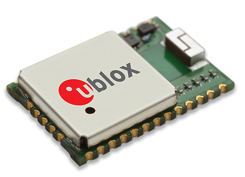
u‑blox has introduced the CAM-M8Q GPS/GLONASS/BeiDou/QZSS antenna module. The module integrates a u-blox M8 satellite receiver IC plus SAW filter, LNA, TCXO, RTC, passives and a pre-tuned GNSS chip antenna in an ultra-small 9.6 x 14.0 x 1.95 mm package. The new module requires only a power source for reliable and accurate satellite positioning anywhere in the world.
Combining low power consumption with high-sensitivity, high jamming immunity and concurrent GNSS operation (GPS/GLONASS, GPS/BeiDou, or GLONASS/BeiDou) the surface-mount CAM-M8Q provides a drop-in solution for satellite positioning in an ultra-small form factor, u-blox said.
“Our u-blox CAM-M8Q is perfect for customers designing highly compact products who want to speed up product development while freeing resources for core activities,” explains Thomas Nigg, vice president of product marketing at u-blox. “The CAM-M8Q is a pre-tuned, performance and cost optimized module providing satellite positioning on an extremely small footprint. It is literally an ‘instant’ positioning solution.”
The u-blox CAM-M8Q module is designed for a wide range of applications such as personal locators, handheld navigators, and wearable electronics as well as vehicle telematics systems used for emergency call, anti-theft, insurance and road pricing. Consistent omni-directional antenna performance helps ensure excellent performance regardless of module orientation.
In addition, the CAM-M8Q allows the internal chip antenna to be used as a backup antenna if the design incorporates an external antenna. This benefits companies where there is a risk that the primary external antenna may malfunction or suffer damage, for example in vehicle tracking systems where damage is possible to the external antenna.
The CAM-M8Q module uses the latest u-blox M8 GNSS receiver chip qualified according to AEC-Q100 and is manufactured in ISO/TS 16949 certified sites. Qualification tests are performed as stipulated in the ISO16750 standard: “Road vehicles – Environmental conditions and testing for electrical and electronic equipment.”
The CAM‑M8Q is form-factor compatible to predecessor modules UC530 and UC530M, allowing the upgrade of existing designs with minimal effort.
Boatracs, Kannad, McMurdo and TSi have combined to form McMurdo Group, a single-vendor provider of end-to-end search and rescue, maritime domain awareness solutions.
McMurdo Group has announced a suite of Automatic Identification System (AIS) survival solutions for enhanced collision avoidance and man overboard (MOB) response in the U.S. recreational boating market. The offerings include AIS beacons, transponders, receivers and software.
AIS is an automatic tracking system used on boats and ships that identifies and tracks nearby AIS-equipped vessels and devices to help avoid collisions. AIS transponders send and receive critical navigation information – such as vessel identification numbers, vessel type, position, course and speed – and graphically display a map of the surrounding vessels and area. AIS receivers are often used in conjunction with AIS-capable computer software for similar tracking and monitoring purposes.
In the event a person with an AIS MOB beacon falls overboard, an AIS signal from the beacon is activated. This signal is then sent to AIS receiving devices where the location of the individual in the water can be pinpointed using GPS positioning and presented on graphical chart maps.
The Smartfind M5 has an on-screen beacon location indicator and audible alarm that is triggered to accelerate rescue efforts. It also has a “buddy list” feature that can identify the specific individual needing MOB assistance. For larger fleets, the McMurdo Group AIS Alarm Notification System extends graphical mapping, alarm notification and messaging capabilities to shoreside fleet management operators.
The McMurdo Group AIS product suite includes the following:
AIS Search and Rescue Transponders (SART) or Beacons
Smartfind S5 – a compact, lightweight, waterproof (to 10 meters) AIS SART with high-visibility buoyant carry-off bag ideal for use on life rafts or survival crafts.
Smartfind S10 – a personal, waterproof (to 60 meters) AIS Man Overboard (MOB) device with built-in flashing light and used by individuals or as an additional device to complement a yacht’s on-board flare pack.
Smartfind S20 – a compact AIS MOB device with integrated light for use in a lifejacket.
AIS Transponders and Receivers
Smartfind M5 AIS Class A Transponder – the industry’s first AIS Class A transponder with color display and AIS MOB and AIS SART alarm with crew list functionality to aid in MOB recovery.
Smartfind M10 AIS Class B Transponder – typically used for smaller vessels, charter boat operators or where the additional features of an AIS Class A transponder are not required (includes an a 30 day data logger).
Smartfind M15 AIS Receiver – economical AIS receiver for all recreational vessels.
AIS Software
PC Viewer – Graphical software package ideal for individual vessel operators (included with the Smartfind M5, M10 and Smartfind M15 products).
AIS Alarm Notification System – Vessel Monitoring System with integrated AIS MOB Alerts and Messaging typically used for ship-to-shore communications.
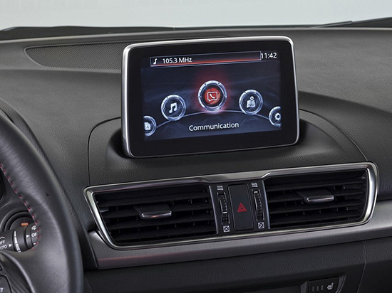
The new Mazda3 infotainment system, which appears in Mazda3’s Active Driving Display, is now running on NNG’s iGO navigation engine, and includes TTS, voice recognition and full 3D navigation.
This solution, supported by Mazda’s MZD Connect, is also reportedly the first on the market to offer an embedded connected-service package with Internet connection provided through the driver’s smartphone. Drivers will be able to access dynamic local search, fuel prices, real-time traffic and weather information free of charge in the first 60 days, and benefit from three years of free map updates.
“Mazda’s new design, KODO, has really inspired us to develop an integrated infotainment system, with knowledge and refined features matching the look and performance of the car,” said Péter Balogh, NNG. “We succeeded in offering cutting-edge solutions in the head unit, enhanced safety, usability and comfort to the driver.”
Hyundai Motor America has selected Verizon Enterprise Solutions to provide a range of connected services including safety, security, diagnostics and infotainment to Hyundai vehicles starting in 2014.
“We selected Verizon to provide the wireless network service for ‘Next-generation Blue Link’ because both customer opinion and various data sources indicate that Verizon provides the best solution to our customers for both coverage and quality,” said Woo-Young Kwak of Hyundai Motor Group.
Hyundai vehicles are distributed throughout the United States by Hyundai Motor America and are sold and serviced through more than 820 dealerships nationwide. According to Forrester Research, the number of vehicles shipped worldwide with embedded connectivity is expected to grow from 5.4 million in 2012 to 36 million in 2018.
“Our agreement with Hyundai expands our long-standing collaboration with a wide range of auto manufacturers throughout the industry to support network engineering, security, cloud solutions, telematics platform, and program management for millions of vehicles in the U.S. and around the world,” said Mark Bartolomeo of Verizon Enterprise Solutions. “We are thrilled to be working with Hyundai to help enhance the driving experience for their customers. It’s the breadth of our expertise combined with the depth of our technology that allows our clients to launch new services and initiatives faster.”
Honda Motor Co. is joining an alliance of companies that will work with Google Inc. on technological innovations for inboard automotive information networks, such as GPS, according to The Asahi Shimbun. Honda will be joining Audi AG, General Motors, and Hyundai Motor Group in the Open Automotive Alliance. The alliance plans to incorporate Google’s Android operating system into automotive communications systems.
Google has also indicated interest in the development of driverless cars.
Toyota Motor Corp., meanwhile, established a joint venture with Microsoft Corp. three years ago to develop information technology for Toyota’s next-generation vehicles. The technology allows for updating map data and other services for the GPS in Toyota vehicles, as well as track stolen vehicles.
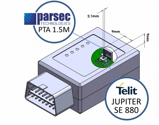
Telit Wireless Solutions and Parsec Technologies today announced that a combination of the companies’ technologies results in a low profile companion solution for GPS receiver and antenna. For host devices able to accommodate higher volumetric symmetry, assembly of the components can be made to fit a 6 x 16 x 8 millimeter volume. A flat component arrangement can yield an ultra-low-profile volume of 6 x 16 x 2.4 millimeters.
“Receivers combining the Parsec PTA/PT Family and Telit’s Jupiter SE880 modules deliver good user experience in finished LBS (location-based services) critical products without sacrificing design flexibility, ease of implementation or cost,” said Michael A. Neenan, CEO and founder of Parsec Technologies, Inc. “The combination is ‘bullet-proof’ in providing a rewarding design experience making RF work reliably, passing end-product regulatory compliance testing without re-test.”
“Miniaturization is a major enabler of new application areas for positioning and M2M,” said Taneli Tuurnala, Vice President and Head of GNSS Division of Telit Wireless Solutions. “With the Parsec antennas, the complete receiver features the industry’s ‘smallest landed footprint,’ making it suitable for use in wearable electronics, UBI devices or adapters for the mobile computing industry.”
Along with miniaturization, the receiver outperforms top traditional designs, handling a loss of 10 dB or greater in GPS signal reaching, for example, the typical OBD port under a vehicle’s dashboard where many usage-based insurance (UBI) dataloggers are installed. The PTA1.5M active antenna delivers the ultra-sensitive Jupiter SE880 micro receiver over 15 dB of additional gain in the operating frequency range. Both companies are making available complete application notes to simplify the engineering effort for system integrators.
The miniature 4.7 x 4.7 millimeter LGA (Land Grid Array), SiRFstarIV-based Jupiter SE880 receiver module employs heterogeneous 3D integrated technology to achieve best-in-class performance in all dimensions critical for regular or size-constrained GPS applications. Its RF front-end employs spatially calibrated waveguide-quality radio paths inside the three-dimensional space of its architecture, reducing parasitic impedances characteristic of traditional 2-D RF designs. Inside, a multi-filter system includes not only the traditional SAW filters typical in GPS receiver designs but also a 2.4-GHz notch-filter capable of nullifying the jamming effects of high-energy radio devices such as Wi-Fi hot-spots, Bluetooth systems, cordless phones, and others, which greatly affect a GPS receiver’s ability to resolve timid satellite signals in the hostile radio environment where they need to operate.
The PTA1.5M, with a gain of 15dB, and PTA1.5x2M, with a gain of 30dB, are tiny GNSS active antenna modules capable of receiving signals down to -192 dBm with frequency centered at 1575.42 (±1.023) MHz. Either model delivers a radiated efficiency greater than 60% when mated to the Jupiter SE880 receiver. Parsec’s PT1233D LNA also has the highest available IP3 at low voltage, helping eliminate interference. Both PTA1.5M and PTA1.5x2M can incorporate the antenna element, an optional SAW filter, the cascadable PT1233D LNA, matching and passives components, on a low cost, easy to integrate 10×16 mm single sided PCBA with “back side” copper clad ground plane. The height of the PTA1.5M and PTA1.5x2M modules vary according to application, allowing their use in even the smallest form factors including Intel’s M.2 Next Generation Form Factor (NGFF) module (23x30x2.4 mm, LxWxH).
The implementation changes and first live tests of BeiDou and Galileo on Teseo-3 GNSS chips developed in 2013 are covered, bringing it to a four-constellation machine. By 2020, we expect to have four global constellations all on the same band, giving us more than 100 satellites — under clear sky, as many as 30 or 40 simultaneously.
By Philip G. Mattos and Fabio Pisoni
Multi-constellation GNSS first became widely available in 2010/2011, but only as two constellations, GPS+GLONASS. Although receivers at that time may have supported Galileo, there were no usable satellites. BeiDou was a name only, as without a spec (an interface control document, or ICD), no receivers could be built. However, the hardware development time of receivers had been effectively shortened: the Galileo ICD had been available for years, BeiDou codes had been reverse-engineered by Grace Gao and colleagues at Stanford, and at the end of 2011 they were confirmed by the so-called test ICD, which allowed signal testing without yet releasing message characteristics or content.
The last weeks of 2012 saw two great leaps forward for GNSS. Galileo IOV3 and 4 started transmitting at the beginning of December, bringing the constellation to four and making positioning possible for about two hours a day. At the end of December, the Chinese issued the BeiDou ICD, allowing the final steps of message decode and ephemeris calculation to be added to systems that had been tracking BeiDou for many months, and thus supporting positioning. The Teseo-2 receiver from STMicroelectronics has been available for some years, so apart from software development, it was just waiting for Galileo satellites; however, for BeiDou it needed hardware support in the form of an additional RF front end. Additionally, while it could support all four constellations, it could not support BeiDou and GPS/Galileo at the same time, as without the BeiDou ICD the spreading codes had to be software-generated and used from a memory-based code generator, thus blocking the GPS/Galileo part of the machine.
The Teseo-3 receiver appeared late in 2013, returning to the optimum single-chip form factor: RF integrated with digital silicon and flash memory in the same package, enabling simultaneous use of BeiDou and GPS/Galileo signals. Multi-constellation in 2012 was GPS+GLONASS, which brought huge benefits in urban canyons with up to 20 visible satellites in an open sky. Now, for two hours a day in Europe while the Galileo IOVs are visible, we can run three constellations, and in the China region, GPS/BeiDou/Galileo is the preferred choice.
This article covers the first tracking of four Galileo satellites on December 4, 2012, first positioning with Galileo, and first positioning with BeiDou in January 2013. It will cover static and road tests of each constellation individually and together as a single positioning solution. Road tests in the United States/Europe will combine GPS/GLONASS/Galileo, while tests in the China region will combine GPS/Galileo/BeiDou. Results will be discussed from a technical point of view, while the market future of multi-constellation hardware will also be considered.
In the 2010–2020 timeframe, GLONASS and BeiDou (1602 MHz FDMA and 1561 MHz respectively) cost extra silicon in both RF and digital hardware, and cause marginal extra jamming vulnerability due to the 50 MHz bandwidth of the front end. The extra silicon also causes extra power consumption.
After 2020, GLONASS is expected to have the L1OC signal operational, CDMA on the GPS/Galileo frequency, and BeiDou is expected both to have expanded worldwide, and also to have the B3 signal fully operational, again on 1575 MHz. At that point we will have four global constellations all on the same band, giving us more than 100 satellites. With a clear sky, the user might expect to see more than 30, sometimes 40, satellites simultaneously.
Besides the performance benefits in terms of urban canyon availability and accuracy, this allows the receiver to be greatly simplified. While code generators will require great flexibility to generate any of the code families at will, the actual signal path will be greatly simplified: just one path in both RF (analog) and baseband (digital) processing, including all the notch filters, derotation, and so on. And this will greatly reduce the power consumption.
Will the market want to take the benefit in power consumption and silicon area, or will it prefer to reuse those resources by becoming dual-frequency, adding also the lower-L-band signals, initially L5/E5, but possibly also L2/L3/L6 ? The current view is that the consumer receiver will go no further than L5/E5, but that the hooks will be built-in to allow the same silicon to be used in professional receivers also, or in L2C implementations to take advantage of the earlier availability of a full constellation of GPS-L2C rather than GPS-L5.
This article presents both technical results of field trials of the quad-constellation receiver, and also the forward looking view of how receivers will grow through multi-frequency and shrink through the growing signal commonalities over this decade.
History
Galileo was put into the ST GPS/GNSS receiver hardware from 2006 to 2008, with a new RF and an FPGA-based baseband under the EU-funded GR-PosTer project. While a production baseband (Cartesio-plus) followed in high volume from 2009, in real life it was still plain GPS due to the absence of Galileo satellites.
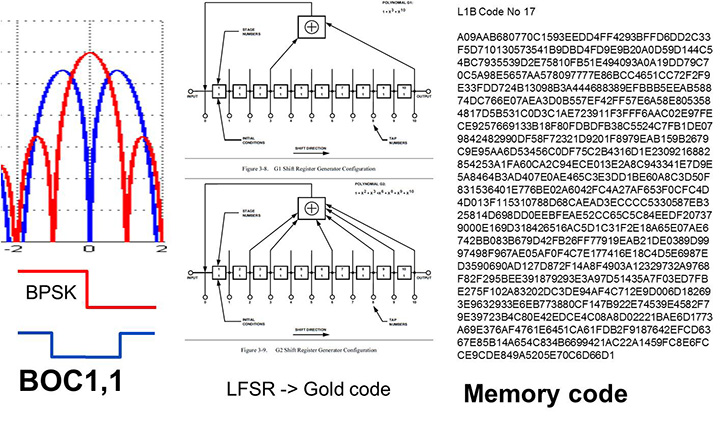
The changed characteristics in Galileo that drove hardware upgrades are shown in Figure 1. The binary offset carrier BOC(1,1) modulation stretches the bandwidth, affecting the RF, while both the BOC and the memory codes affect the baseband silicon in the code-generator area.
Figure 1. Changes for Galileo.
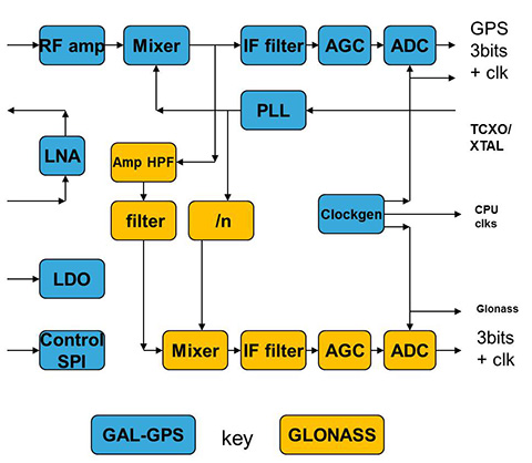
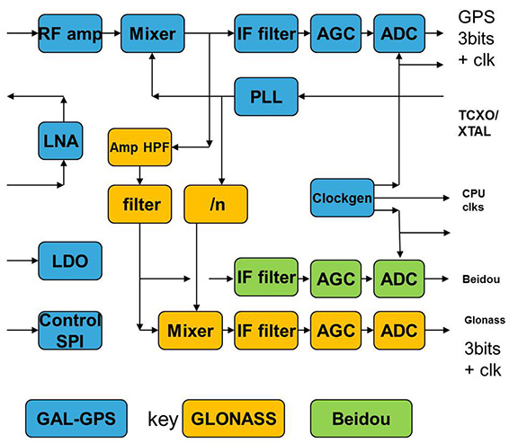
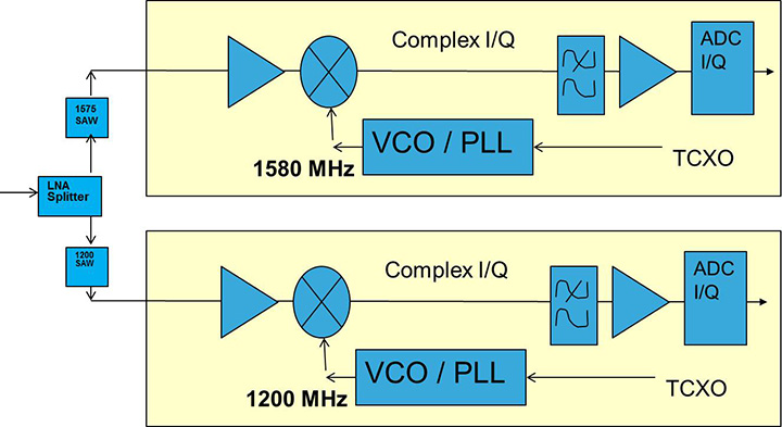
Next was the return to strength of the GLONASS constellation, meaning receivers were actually needed before Galileo. However the different center frequency (1602 MHz), and the multi-channel nature of the FDMA meant more major changes to the hardware. As shown in Figure 2 in orange, a second mixer was added, with second IF path and A/D converter.
Figure 2. Teseo-2 RF hardware changes for GLONASS.Figure 3. Teseo-2 and Teseo-3 baseband changes for GLONASS.
The baseband changes added a second pre-processing chain and configured all the acquisition channels and tracking channels to flexibly select either input chain. Less visible, the code-generators were modified to support 511 chip codes and 511kchips/sec rates.
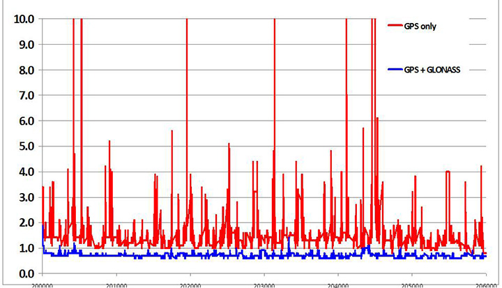
Teseo-2 appeared with GPS/GLONASS support in 2010, and demonstrated the benefit of GNSS in urban canyons, as shown by the dilution of precision (DOP) plot for central London in Figure 4. The GPS-only receiver (in red) has frequent DOP excursions beyond limits, resulting either in bad accuracy or even interrupted fix availability. In contrast, the GNSS version (in blue) has a DOP generally below 1, with a single maximum of 1.4, and thus 100 percent availability. Tracking 16 satellites, even if many are via non-line-of-sight (NLOS) reflected paths, allows sophisticated elimination of distorted measurements but still continuous, and hence accurate, positioning.
Figure 4. DOP/accuracy benefits of GNSS.
BeiDou
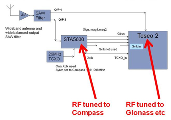
Like Galileo, BeiDou is a story of chapters. Chapter 1 was no ICD, and running on a demo dual-RF architecture as per the schematic shown in Figure 5. Chapter 2 was the same hardware with the test ICD, so all satellites, but still no positioning. Chapter 3 was the full ICD giving positioning in January 2013 (Figure 6), then running on the real Teseo-3 silicon in September 2013, shown in Figure 7.
Figure 5. Demo Teseo-2 dual RF implementation of BeiDou.Figure 6. Beidou positioning results.Figure 7. Teseo 3 development board.
The Teseo-3 has an on-chip RF section capable of GPS, Galileo, GLONASS and BeiDou, so no external RF is needed.
The clear green space around the Teseo-3 chip in the photo and the four mounting holes are for the bolt-down socket used to hold chips during testing, while the chip shown is soldered directly to the board. Figure 8A shows the development board tracking eight BeiDou satellites visible from Taiwan.
However, the silicon is not designed to be single-constellation; it is designed to use all the satellites in the sky. Figure 8b shows another test using GPS and BeiDou satellites simultaneously.
Figure 8A. Beidou.Figure 8b. GPS+Beidou.
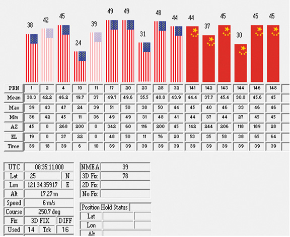
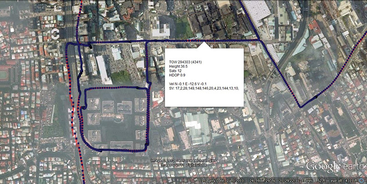
A mobile demo on the Teseo-3 model is shown running GPS plus BeiDou in Figure 9, a road test in Taipei. Satellites (SV) up to 32 are GPS, those over 140 are BeiDou, in the status window shown: total 13 satellites in a high-rise city area, though many are non-LOS.
Figure 9. GPS + Beidou roadtrack in Taipei.
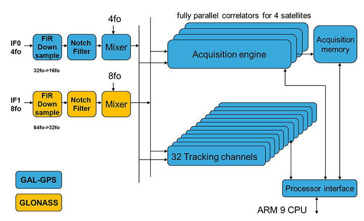
Extending the hardware to add BeiDou, which is on 1561 MHz and thus a third center frequency, meant adding another path through the IF stages of the on-chip radio. After the first mixer, GPS is at 4 MHz, and GLONASS at about 30 MHz, but BeiDou is at minus 10 MHz. While the IF strip in general is real, rather than complex (IQ), the output of the mixer and input to the first filter stage is complex, and thus can discriminate between positive frequencies (from the upper sideband) and negative ones (from the lower sideband), and this is normally used to give good image rejection. In the case of BeiDou, the filter input is modified to take the lower sideband, that is, negative frequencies, and a second mixer is not required; the IF filter is tuned to 10 MHz. The new blocks for BeiDou are shown in green in Figure 10. The baseband has no new blocks, but the code generator has been modified to generate the BeiDou codes (and, in fact, made flexible to generate many other code types and lengths). Two forms of Teseo-3 baseband are envisaged, the first being for low-cost, low-current continues to have two input paths, so must choose between GLONASS and BeiDou as required. A future high-end model may have an extra input processing path to allow use of BeiDou and GLONASS simultaneously.
Figure 10. Teseo-3 RF changes for Beidou shown in green.
Galileo Again
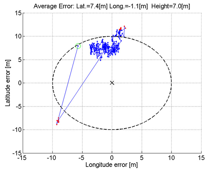
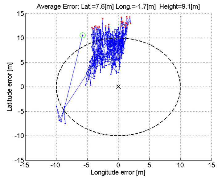
Maintaining the chronological sequence, Galileo gets a second chapter in three steps. In December 2012, it was possible for the first time to track four IOV satellites simultaneously, though not to position due to the absence of valid orbit data. In March 2012, it was possible for the first time to demonstrate live positioning, and this was done using Teseo-2 simultaneously by ESA at ESTEC and STMicro in Naples and Milan, our software development centres.
The demos were repeated in public for the press on July 24, 2013, at Fucino, Italy’s satellite earth station, with ESA/EC using the test user receiver (TUR) from Septentrio, and ST running simultaneous tests at its Italian labs. Figure 11 and Figure 12 show the position results for the data and pilot channels respectively, with independent LMS fixes. In real life, the fixes would be from a Kalman filter, and would be from a combined E1-B/E1-C channel, to take advantage of the better tracking on the pilot.
Good accuracy is not expected from Galileo at this stage. The four satellites, while orbited to give good common visibility, do not also give a good DOP; the full set of ground monitoring stations is not yet implemented and cannot be well calibrated with such a small constellation. Finally, the ionospheric correction data is not yet available. Despite these problems, the residuals on the solutions, against a known fixed position for the rooftop antenna, are very respectable, shown in Figure 13.
Figure 13. Galileo residuals, L1-B.
The common mode value is unimportant, representing only an offset in the receiver clock, and 10 meters is about 30 nanoseconds. The accuracy indicator is the spread between satellites, which is very respectable for a code-only receiver without full iono correction, especially around 640 on the TOW scale, where it is less than 2 meters. The rapid and major variation on the green data around t=400 is considered to be multipath, as the roof antenna is not ideally positioned with respect to other machinery and equipment also installed on the roof.
QZSS and GPS-III/L1C
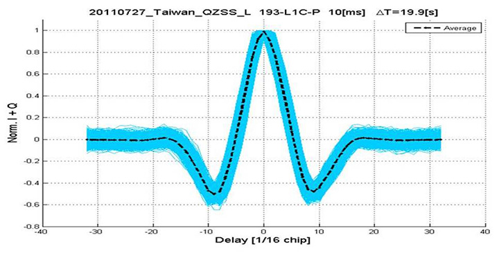
Teseo-2 has supported the legacy (C/A code) signal on QZSS for some time, but Teseo-3 has been upgraded to handle the GPS-III/L1-C signal, waiting for modernized GPS. This signal is already available on the QZSS satellite, allowing tests with real signals. Significant changes were required in the baseband hardware, as the spreading code is a Weill code, whose generation complexity is such that it is generated once when the satellite is selected, then replayed real time from memory. Additionally it is long, in two domains. It is 10230 chips — that is, long to store but also long in time, with a 10-millisecond epoch. On Teseo-3, the legacy C/A code is used to determine code-phase and frequency before handing over to the Weill code for tracking.
Using a long-range crystal ball and looking far into the future, a model of the future Teseo-4 DSP hardware is available, with 64 correlation taps per satellite. Running this on the captured QZSS L1-C signal gives the correlation response shown in Figure 14. Having multiple taps removes all ambiguity from the BOC signal, simultaneously removing data transitions, which can alternatively be pre-stripped using the known pilot secondary code (which on GPS III is 5 dB stronger than the data signal). The resultant plot represents 2,000 epochs, each of 10 milliseconds, plotted in blue, with integrated result for the full 20 seconds shown in the black dashed line. Assuming vehicle dynamics is taken out using carrier Doppler, this allows extremely precise measurement of the code phase, or analysis of any multipath in order to remove it. This RF data was captured on a benign site with a static antenna, so it shows little distortion.
Figure 14. L1-C tracking on QZSS satellite.Figure 15. Dual RF implementation of dual-band front end.
The Future
Having already built in extreme flexibility to the code generators to support all known signals and generalized likely future ones, the main step for the future is to support multiple frequencies, starting with adding L5 and/or L2, but as before, ensuring that enough flexibility is built in to allow any rational user/customer choice. It is not viable for us to make silicon for low-volume combinations, nor to divide the overall market over different chips. Thus our mainstream chip must also support the lower volume options.
We cannot, however, impose silicon area or power consumption penalties on the high-volume customer, or he will not buy our product.
Thus, our solution to multi-frequency is to make an RF that can support either band switchably, with the high band integrated on the volume single-chip GNSS. Customers who also need the low band can then add a second RF of identical design externally, connected to the expansion port on the baseband, which has always existed for diagnostic purposes, and was how BeiDou was demonstrated on T2. By being an RF of identical design to the internal one, it incurs no extra design effort, and would probably be produced anyway as a test chip during the development of the integrated single-chip version. Without this approach, the low volume of sales of a dual-band radio, or a low-band radio, would never repay its development costs.
Conclusions
All four constellations have been demonstrated with live satellite signals on Teseo-2, a high-volume production chip for several years, and on Teseo-3 including use in combinations as a single multi-constellation positioning solution. With the advent of Teseo-3, with optimized BeiDou processing and hardware support for GPS-3/L1C, a long-term single-chip solution is offered.
For the future, dual-frequency solutions are in the pipeline, allowing full advantage of carrier phase, and research into moving precise point positioning and real-time kinematic into the automotive market for fields such as advanced driver-assistance systems.
Acknowledgments
Teseo III design and development is supported by the European Commission HIMALAYA FP-7 project.
This article is based on a technical paper first presented at ION-GNSS+ 2013 in Nashville, Tennessee.
ST GPS products, chipsets and software, baseband and RF are developed by a distributed team in: Bristol, UK (system R&D, software R&D; Milan, Italy (Silicon implementation, algorithm modelling and verification); Naples, Italy (software implementation and validation); Catania, Sicily, Italy (Galileo software, RF design and production); Noida, India (verification and FPGA). The contribution of all these teams is gratefully acknowledged.
Philip G. Mattos received an external Ph.D. on his GPS work from Bristol University. Since 1989 he has worked exclusively on GNSS implementations, RF, baseband and applications. He is consulting on the next-generation GNSS chips, including one-chip GPS (RF+digital), and high-sensitivity GPS and Galileo for indoor applications, and combined GPS/Galileo/GLONASS chipsets. In 2008-2009, he re-implemented LORAN on the GPS CPU, and in 2009-2010 led the GLONASS implementation team. He is leading the team on L1C and BeiDou implementation, and the creation of totally generic hardware that can handle even future unknown systems.
Fabio Pisoni has been with the GNSS System Team at STMicroelectronics since 2009. He received a master’s degree in electronics from Politecnico di Milano, Italy, in 1994. He was previously with the GNSS DSP and System Team in Nemerix SA and has earlier working experience in communications (multi-carrier receivers).
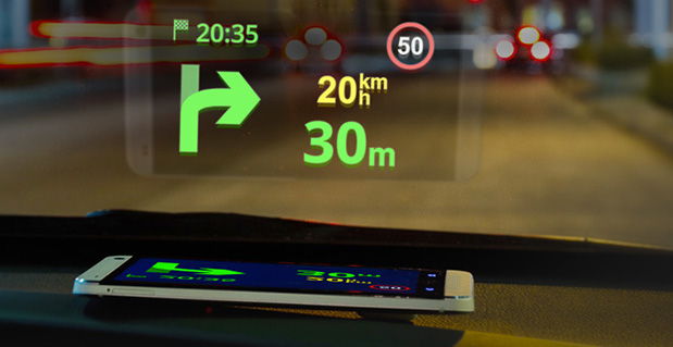
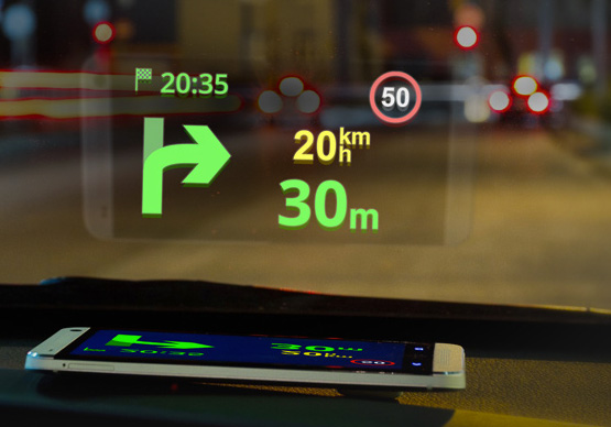
Sygic has announced a new product to make driving safer. Sygic’s Heads-up-Display (HUD) product projects navigation information onto drivers’ windshields, so they never have to take their eyes off the road to look down at their navigation software.
The product comes at a critical time for the holiday travel and shopping season, which is one of the most auto accident-heavy periods of the year. Sygic’s HUD is available as an in-app purchase for $4.99 and doesn’t need an expensive add-on product, as the projection can be emitted right from the Sygic GPS Navigation app on any iOS and Android phone or tablet.
Using Sygic’s HUD interface is straightforward. Drivers activate the feature from the app’s navigation menu, flip the screen via pop-up menu, and place their phone on their dashboard. The specially optimized interface will then
reflect clearly on the car’s windshield, displaying navigation information without the need for any expensive accessories. Sygic’s HUD feature gives them the full Sygic experience, complete with features like live traffic and turn-by-turn voice guidance.
“As we head into the heavy travel season, we hope our HUD will help drivers stay safe on the roads so they can spend more time with their family and friends and less time driving down heavily-trafficked and dangerous winter road conditions,” said Sygic CEO Michal Štencl.
Features of Sygic GPS Navigation include:
• Offline maps that don’t require a cellular data connection
• Turn-by-turn voice-guided GPS navigation
• 3D cities and landscapes
• Voice guidance in more than 40 languages
• Multi-stop routes and Drag & Drop route editing
• Speed limit display and audio warning
• SOS/Help to find assistance nearby
• Interactive map – tap on any street, POI, or photo to choose action
• Robust integration with third party
services like Groupon and TripAdvisor to find
things like deals, restaurants, hotels, attractions and more
• New speed cameras feature with a
constantly-updated database of stationary and mobile speed traps
Unlike other map services, data in Sygic: GPS
Navigation is stored on the user’s phone instead
of streamed from the Internet, which means that
Sygic users don’t have to worry about running up
against their cellular data caps by using GPS
navigation or getting lost in an area with poor
cell reception. When Sygic’s users are online,
they now have access to other helpful features
like real-time traffic and road incident sharing with other drivers.
Sygic GPS Navigation, now upgraded to version
13.3, is available in the iOS App Store and
Google Play, while the HUD feature can be
purchased from within the app for $4.99.
– See more at:
http://www.gisuser.com/content/view/31596/2/#sthash.goudUtyE.dpuf