Spirent Federal Systems has been awarded a contract to support anechoic chamber testing for a major U.S. military agency.
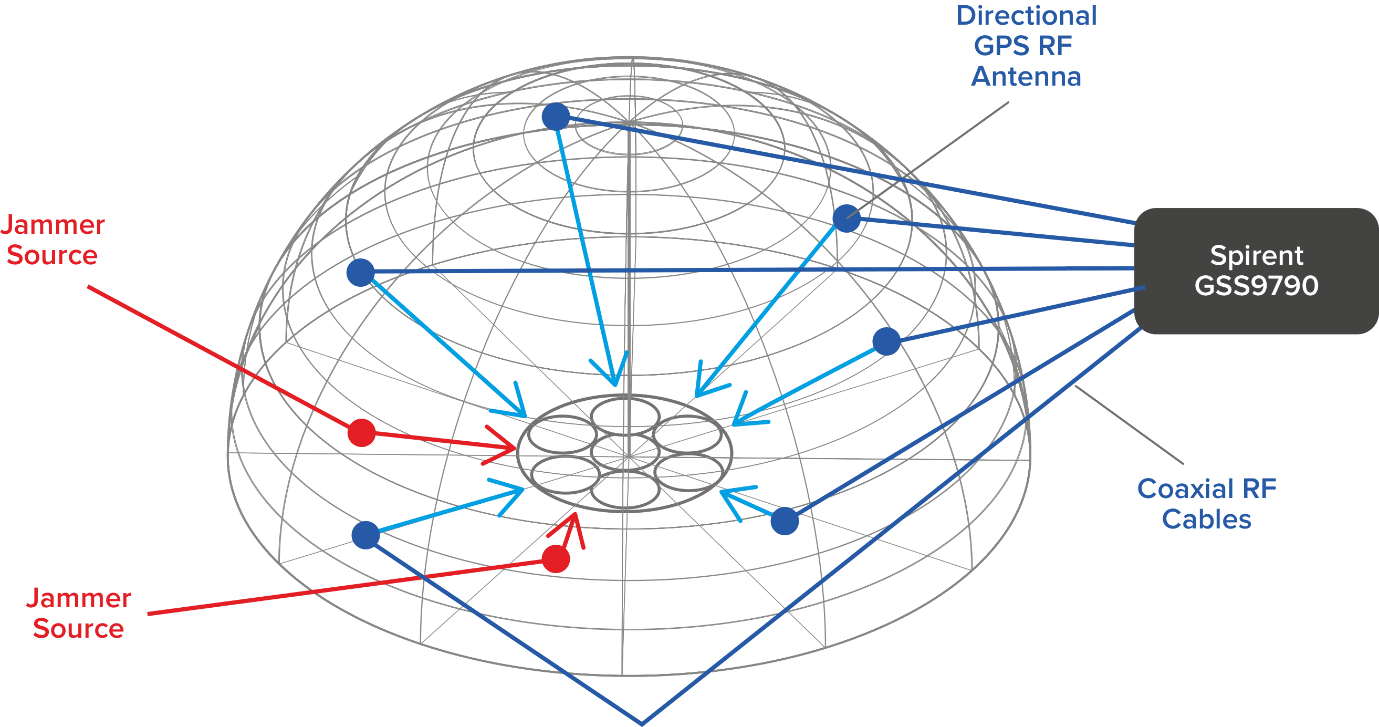
Spirent’s GSS9790 multi-output, multi-GNSS RF constellation wave-front simulator will be used as the signal generator attached to multiple transmission antennas for broadcast into the chambers.
Within this design, the antennas are structurally distributed to represent the correct arrival vectors of the simulated satellite signals on the device under test, creating the most realistic test environment possible. In addition, the GSS9790 supports interference sources located anywhere in the chamber to imitate different threat scenarios.
Image: Spirent
“Interference can threaten GNSS signals in multiple ways,” explained Jeff Martin, VP Sales. “We recognize the need for controlled, repeatable conditions to combat these threats. The GSS9790 delivers all the tools needed to successfully mitigate them.”
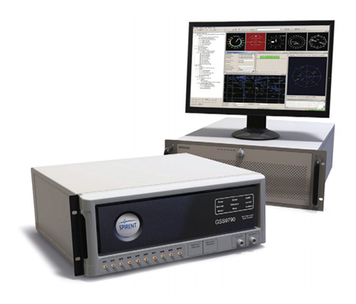
The GSS9790 simulator. (Photo: Spirent)
The Spirent GSS9790 supports classified Y-code, SAASM and M-code and can be found in key government labs across the country.
The Spirent GSS9790 enables verification of CRPA systems, spatial testing of single-antenna devices, and real-world-time-synchronized indoor GNSS implementations. The system is a development of the Spirent GSS9000. Combined with Spirent’s SimGEN software, it offers a powerful test platform for anti-jam and interference testing.
America’s space assets are in danger from an array of kinetic, non-kinetic, electronic and cyber threats. These are wielded by nation states, primarily China, Russia, Iran and North Korea, though there are other countries as well as non-state actors.
On March 30, the Center for Strategic and International Studies (CSIS) Space Threat Assessment 2020 released a catalog that highlights the ways essential space-based services Americans rely upon can be degraded or eliminated. But it doesn’t do much to “assess threats.”
That said, it is still an impressive, useful and informative document. Some of what it doesn’t say can be inferred, and it provides a clear conclusion for policy makers and others.
Threat assessments are typically undertaken to:
Identify potential dangers,
Evaluate their credibility,
Weigh potential impact, and
Estimate the probability of the threat turning into an incident
This CSIS report generally stops after accomplishing the first two tasks.
Nonetheless, it is very instructive in a several ways.
Interference with Space Systems
First, it is packed with examples of how America’s adversaries have armed themselves, and stories about interference with space-based systems. Whether it is information about China training troops to use direct-ascent weapons, or reports about Russia’s mass GPS spoofing, the report’s matrix of threat categories is well supported by examples of real-world events.
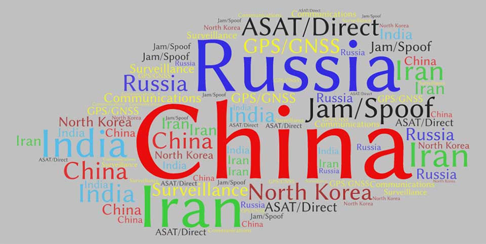
Second, while the report doesn’t overtly rank threats and adversaries, it is possible to infer some generalities by the attention the report devotes to each. Among potential adversaries, China was mentioned the most by far — 429 times. It was followed by Russia (275), Iran (206), India (141), and North Korea (132).
This word cloud from CSIS Space Threat Assessment 2020 shows that China received by far the most mentions, followed by Russia. (Image: RNT Foundation)
Jamming and spoofing
Jamming and spoofing seem to be the most credible threats and were mentioned 188 times, with ASAT and direct-ascent closely following with 179 mentions. This particular word count might not be reflective, though, as the report contains many more examples of real-world jamming and spoofing than ASAT and direct-ascent.
And of all the types of satellites that could be threatened, GPS/GNSS was the clear leader at 98 mentions, with communications and surveillance coming in at 42 and three, respectively.
In all fairness, at only 80 pages, it’s not possible for Space Threat Assessment 2020 to be an exhaustive analysis. And doing more would likely require making it classified. Then this exceptionally educational reference would not be nearly as available for the policy making audience that sorely needs it.
And it does provide an excellent bottom line for those making macro-level decisions about space policy and budgets going forward. From the report’s “What to Watch” section:
Electronic counterspace weapons continue to proliferate at a rapid pace in both how they are used and who is using them. Satellite jamming and spoofing devices are becoming part of the every-day arsenal for countries that want to operate in the gray zone — i.e., below the threshold of overt conflict. The jamming and spoofing of satellites has become somewhat common, and without strong repercussions these adverse activities could gradually become normalized…
One should expect that the rate of satellite jamming and spoofing incidents will only increase as these capabilities continue to proliferate and become more sophisticated in the coming years.
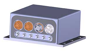
Quantum Reversal has released the QR100, a novel L1/L2 GPS anti-jamming unit, and the QR101, an L1/L2 GPS anti-jamming antenna, designed for the commercial market to solve the issue of unintentional RF interference or jamming.
The QR100 uses three external passive or active GPS antennas of the user’s choice, while the QR101 has three passive L1/L2 antennas embedded inside the enclosure. Low power consumption of 1 Watt and low cost allow for a wide range of applications where the continuity of GPS service is a must.
“Clever RF signal nulling in the RF domain allowed us to eliminate the need for signal processing, and hence, significantly reducing the power consumption when compared to existing military solutions,” said Waldemar Kunysz, Quantum Reversal President and CTO.
The technology prevents the RF front-end from saturation when the interfering signal is very strong due to its power or close proximity to the antenna. This extends the range of the operation for mobile applications and reduces susceptibility to nearby sources of interference for any type of fixed installations.
What is or would be the best policy response from Congress and/or executive branch agencies to the growing threats to GPS from jamming and interference?
Brad Parkinson
“Homeland Security has declared GPS to be an essential system to virtually all of our infrastructure. It is time to install a national system to identify and shut down interference. As part of that, all cell phones should periodically report interference to that national system and allow law enforcement to pinpoint and eliminate offenders.”
-Bradford W. Parkinson
Stanford Center for Position, Navigation and Time
Allison Brown
“On Dec. 5, 2018, the president signed into law the National GPS Timing Resilience and Security Act tasking the Secretary of Transportation with establishing a backup timing system for GPS within two years. To date, only limited technology demonstrations have been performed. Congress needs to fund the Department of Transportation to rapidly acquire and deploy a back-up timing capability, using available commercial solutions, to assure resilience within the Air Traffic Control system and other critical infrastructure to GPS jamming or spoofing.”
-Alison Brown
NAVSYS Corporation
Members of the EAB
Tony Agresta Nearmap
Miguel Amor Hexagon Positioning Intelligence
Thibault Bonnevie SBG Systems
Alison Brown NAVSYS Corporation
Ismael Colomina GeoNumerics
Clem Driscoll C.J. Driscoll & Associates
John Fischer Orolia
Ellen Hall Spirent Federal Systems
Jules McNeff Overlook Systems Technologies, Inc.
Terry Moore University of Nottingham
Bradford W. Parkinson Stanford Center for Position, Navigation and Time
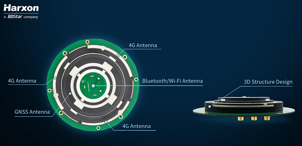
Architecture of the X-Survey antenna. (Image: Harxon)
Blocking interference
Interference can be blocked at the data-collection stage, using an advanced antenna.
Harxon’s X-Survey is a compact high-precision GNSS antenna. It provides superior navigation and communication performance in surveying applications. A frontal band-pass filter setting effectively rejects out-of-band signals before they enter the low-noise amplifier of the antenna for signal augmentation.
Meanwhile, the filter itself has insertion loss, making a low insertion loss filter a prerequisite for optimal system noise reduction. To avoid this situation, X-Survey employs ceramic filter with low signal loss and in-band flatness to significantly improve system anti-interference capability and ensure reliable signal receiving.
The mosaic module provides AIM+ mitigation technology. (Image: Septentrio)
Septentrio began to tackle the interference problem more than 20 years go, designing and manufacturing high-precision GNSS receiver technology with emphasis on reliability and robustness. The result is Advanced Interference Monitoring and Mitigation (AIM+) technology which secures the company’s GNSS receivers against jamming and spoofing interference. AIM+ has recently been upgraded with an extended anti-spoofing functionality.
Building on its existing spoofing detection, Septentrio has developed a new anti-spoofing algorithm for its commercial receivers. The algorithm leverages Galileo Open Service Navigation Message Authentication (OSNMA) for spoofing resistance. It was developed in the framework of the GSA FANTASTIC project with the goal of improving the security of timing in critical infrastructure.
Mobile devices and cloud applications increasingly rely on GNSS technology used by telecom companies. Having secure and robust GNSS receivers in telecom infrastructure is key to reliable mobile and positioning services.
Alternative signals
Prototype design of the PNT-5500. (Image: Jackson Labs)
A new reference receiver, Jackson Labs’ PNT-5500, includes a custom Satelles/Iridium (STL) and GPS receiver, and an optional Edge Grandmaster/PTP1588 capability.
Using STL signals received directly through a small antenna mounted on the device, the PNT-5500 provides nanosecond timing synchronization in GPS-challenged environments, including deep indoors (no rooftop antenna required). It provides secure timing during GPS jamming and spoofing events. The unit is designed for high-volume, low-cost telecom small-cell synchronization, and is optionally available with holdover oscillators such as DOCXO and CSAC atomic clocks.
While GPS is vulnerable to jamming and spoofing, the PNT-5500 uses the Iridium infrastructure to provide assured timing that is impervious to spoofing and provides 1,000X higher signal strength compared to GPS, producing jamming resilience and deep-indoor reception. The system is designed to be fully interoperable with legacy equipment, for a low-cost, fully-deployed Assured PNT capability alternative to GNSS today.
Assessing vulnerability
Image: Qascom
Qascom offers several robust PNT services and products, including vulnerability assessment, robust navigation and interference localization.
Vulnerability assessment is the key proactive measure, using cutting-edge signal generators to design and test tomorrow’s receivers. For example, Qascom’s QA707 GNSS simulator tests receivers against emerging jamming and spoofing threats, allowing OEMs to discover in advance any potential vulnerability that may affect the availability and the integrity of the signal.
Robust navigation is supported by advanced mitigation algorithms, equipped with pre and post-correlation algorithms, as well as the inclusion of sensor fusion and dead-reckoning features.
Qascom’s attack detection products include external monitoring networks that support GNSS receivers. These networks provide an accurate perception of the operational environment, allowing threat characterization, classification and forecast. For instance, Qascom’s QB100 enables the simultaneous threat detection and localization by means of a monitoring cluster that delivers 24/7 situational awareness to a set of target receivers within the protection area.
Reliable timing
Meinberg provides GNSS timing solutions for nearly every application type. Its reliable systems are based on firmware built from the ground up by an in-house team of expert engineers. All Meinberg firmware is constantly checked and updated to ensure it adapts to evolving industry standards.
The company’s synchronization systems use a built-in Meinberg GPS receiver or combined GPS/GLONASS clock. They also support a broad range of reference time sources, including 1 PPS, 10 MHz, inter-range instrumentation group time codes (both direct current level shift and amplitude modulated), or network time protocol (NTP) servers. This redundancy in synchronization sources means Meinberg’s systems are protected against a loss of signal. Furthermore, to ensure the correctness of the reference time and date, an intuitive Secure Hybrid System (SHS) feature includes an independent secondary clock for enhanced plausibility checks.
For superior holdover performance, the Meinberg XHERB (with one or two Rubidium modules from Stanford Research) can be added to the Meinberg Intelligent Modular Synchronization (IMS) time and frequency systems. If the reference clock loses its sync source, the XHE chassis will provide the sync reference for the IMS chassis based on its holdover performance.
An independent technical review published earlier this month found sufficient data in three government-conducted tests to assess the risk of using frequencies near the GPS band for a ground-based communications network — specifically, the one proposed by Ligado Networks. The panel rejected two tests sponsored by Ligado Networks, saying they did not meet minimum criteria for inclusion or use.
The testing and various hearings before the Federal Communications Commission (FCC) come in response to increasing demand for commercial spectrum to support broadband wireless communications. The FCC and other branches of U.S. government are giving serious consideration to repurposing various radio frequencies, including the satellite communications bands next to GPS, to accommodate this.
Ligado Networks has petitioned the FCC to repurpose satellite frequencies near GPS to also support terrestrial telecom services, effectively transferring its license for space-based broadcasting to powerful terrestrially-based broadcast towers. Ligado’s custom networks would provide services for industrial operations such as power grids and connectivity for drones and driverless cars, in addition to consumer broadband services.
The National Executive Committee of the government’s National Coordination Office for Space-Based Positioning, Navigation, and Timing released the assessment by its National Space-Based PNT Systems Engineering Forum (NPEF) of testing methodologies used to analyze the impacts of adjacent band interference on GPS receivers. The assessment is also known as the “gap analysis.”
The NPEF evaluated five tests performed by the following organizations, the first three of them government organizations and the last two private tests sponsored by Ligado with little or no public or government input:
Federal Communication Commission (FCC)-mandated Technical Working Group (TWG) — done in 2011.
National Space-Based PNT Systems Engineering Forum (NPEF) — done in 2011.
Department of Transportation (DOT) Adjacent Band Compatibility (ABC) — done in 2017 but not previously released.
Roberson and Associates (RAA)
National Advanced Spectrum and Communications Test Network (NASCTN).
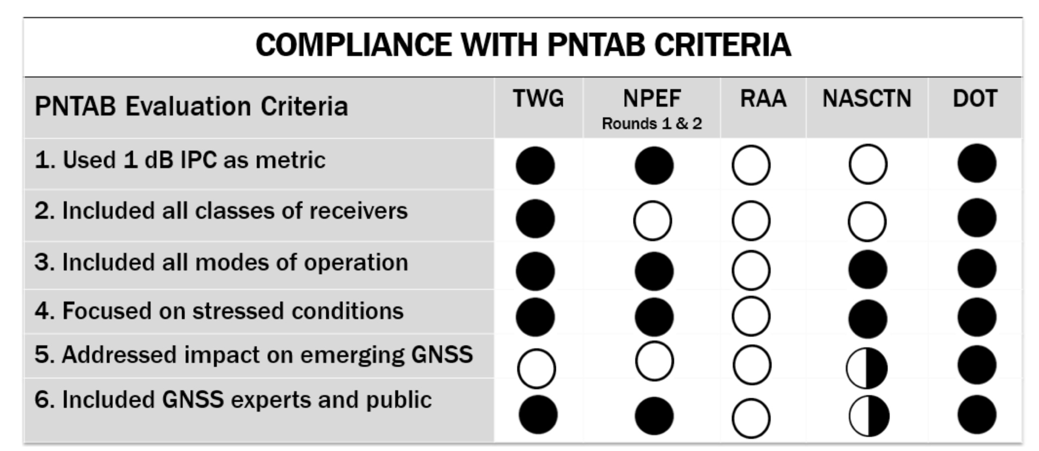
The gap analysis concluded that the results from the first three tests are sufficient and appropriate to inform spectrum policy makers on the major impacts of a proposed LTE network on GPS receivers. The DOT test results revealed the power levels that GPS and GNSS receivers can tolerate from interference sources in the adjacent band in an effort to inform the enforcement of a GPS interference protection criterion.
PNT Advisory Board’s set of minimum criteria. The two Ligado-sponsored tests are the RAA and the NASCTN. (Image: PNTAB)
The NPEF team found the scope and framework of the last two tests, sponsored by Ligado, to be insufficient when evaluated against the PNT Advisory Board’s set of minimum criteria. Key among these criteria is one that specifies use of the internationally accepted 1 dB degradation Interference Protection Criterion (IPC): a one-decibel (1 dB) degradation in C/N0, the carrier-to-noise power density ratio. Ligado has tried to redefine the standard measurement of interference to one more in its favor: a change in positioning and timing accuracy.
For further background on this and other aspects of the gap analysis, see the January 2018 GPS World article by Brad Parkinson, “A Grave Threat to GPS and GNSS.”
The NPEF strongly recommended that decisions impacting the GPS radio frequency environment be informed by data from tests that align with the PNTAB’s set of minimum criteria and with full consideration of the potential operational, scientific, and economic impacts.
The full gap analysis study can be downloaded here.
The NPEF is co-chaired by the Departments of Defense and Transportation and consists of representatives from at least 14 federal agencies.
The cellular 5G standard targets latencies under 1 millisecond, data rates of up to 10 gigabits per second, extremely high network reliability and better accuracy in positioning. With location awareness becoming an essential feature in many new markets, positioning is considered as an integral part of the system design of upcoming 5G mobile networks.
The cellular industry is currently implementing Long-Term Evolution (LTE)-Advanced, which might be called “4G” mobile broadband. Simultaneously, the industry is preparing the next step, a fifth-generation (5G) system. It will process communication 10 times faster than 4G, according to experts. 5G rollout will be complete in many international metropolitan areas by 2020.
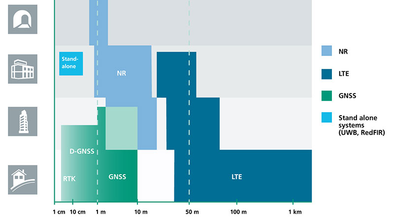
Positioning Performance for 5G NR and other technologies in different environments. (Image: Fraunhofer IIS)
Adaptive array antennas
In addition to the precise positioning it will afford, 5G shares another characteristic with GPS/GNSS: adaptive array antennas for digital beamforming (DBF). Adaptive arrays have many advantages for PNT, primarily in mitigation for multipath, jamming and spoofing.
Emerging applications of DBF in 5G involve dense networks of picocells, small cellular base stations that typically cover a small indoor area. Picocells extend coverage where outdoor signals do not reach well, and add network capacity in areas with very dense phone usage. 5G architectures will use adaptive array technology to achieve high data rates, spectrum reuse and communications robustness.
The implications for PNT are that 5G will require improved (relative) PNT to operate effectively, and picocells will be a source of PNT information in constrained environments.
5G involves massive directional communications via multiple-input, multiple-output (MIMO), enabling high-bandwidth communications in fading (multipath) channels by using multiple antenna inputs to adapt to channels. It can do this without knowledge of user location, but it adds to the processing complexity. The directional capability can enable multiple users to be serviced in a picocell at different frequencies, while permitting spectrum re-use by nearby picocells through narrow beamwidth and the limited range of millimeter-wave (mmWave) frequencies.
The PNT implications of 5G architectures, according to Gary McGraw of Rockwell Collins, are that 5G picocells will be synergistic with PNT in challenged environments — naturally, indoor and dense urban. They will necessitate development of distributed, networked PNT processing and infrastructure.
Fraunhofer
The 5G positioning framework will integrate a multitude of sensors into a hybrid positioning scheme, according to the Fraunhofer Institute for Integrated Circuits (IIS) in Germany. Fraunhofer IIS is currently prototyping low-latency and high-precision positioning systems for legacy LTE and future 5G New Radio (5G NR).
5G NR enables positioning by providing high bandwidths for precise timing, new frequency bands at mmWave, massive MIMO for accurate angle-of-arrival estimation and new architectural options that support positioning. Improved accuracy, robustness and latency can be achieved, according to the institute.
5G provides fast and reliable access to moving objects to achieve time-critical process control and optimization in industrial environments. Increased contextual awareness of goods, parts, machines and workers will enable new interaction and collaboration, the institute said.
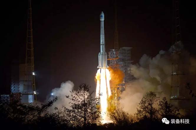
China launched two BeiDou-3 navigation satellites into space on Jan. 12 as part of efforts to enable its BeiDou system to provide navigation and positioning services to countries along the Belt and Road by the end of 2018. The Belt and Road Initiative aims to create the world’s largest platform for economic cooperation, encompassing China, Southeast Asia, South Asia, Central and Western Asia, Middle East and Africa, and Central and Eastern Europe.
The twin satellites are coded MEO-7 and MEO-8, the 26th and 27th satellites in the BeiDou Navigation Satellite System. They are based on a newly developed dedicated satellite bus that features a phased-array antenna for navigation signals and a laser retro-reflector. They each weigh about one metric ton, and both have two deployable solar arrays; their design life is 12 years. This was the first BeiDou launch in 2018, which will see an intensive further launch schedule throughout the year.
In his December 2017 “Directions” article in GPS World, Changfeng Yang, chief BeiDou system architect, wrote that “Eighteen BD-3 MEO satellites and one BD-3 GEO satellite will be launched by around the end of 2018. Upon the deployment of those 19 satellites, BD-3 will possess the initial operational capability and serve the countries along the Belt and Road.”
This would bring the constellation to an initial operational capability before the end of this year. China targets completion of the fully operational global system in 2020.
More interference potential from another tower set
Satellite operator Iridium asked the Federal Communications Commission (FCC) in April 2017 to modify its license to add a new class of ground stations called Certus for expanded terrestrial, maritime and aeronautical operations.
Iridium’s 66-satellite constellation provides, in addition to mobile communications signals, the Satelles time and location service: microsecond timing accuracy and 20- to 50-meter unaided position accuracy worldwide (see the “Innovation” column, July 2017 GPS World).
GPSIA. The GPS Innovation Alliance (GPSIA) commented in September, “GPSIA seeks to ensure that radio navigation satellite service (RNSS) receivers operating in the 1559–1610 MHz band are adequately protected from out-of-band emissions (OOBE) generated from the new Certus mobile Earth station (MES) terminals that will operate on the second-generation Iridium satellite system.
“GPSIA and Iridium are actively engaged in constructive discussions regarding the adequacy of that protection, but no final resolution has yet been reached. [….]
“In the unlikely event that GPSIA is unable to reach an agreement with Iridium, it asks the commission to impose limitations on the operation of Certus terminal devices to protect GPS/RNSS operations in the 1559–1610 MHz band at a level equivalent to what terrestrial terminals in the same and other frequency ranges provide at –95 dBW/MHz.”
Hexagon. Hexagon, the parent company of GPS manufacturer NovAtel, commented on Jan. 8, “Certain statements in the modification application regarding output power and amount of terminals to be deployed cause great concern regarding the unimpeded operation of radio navigation satellite service (RNSS) receivers. The application does not include enough information to simulate the impact properly.
“Hexagon politely requests that the FCC will exercise the same due diligence [as] during previous modification applications close to the RNSS bands (for example docket 11-109) and establish a technical working group or a similar testing process that ensures unimpeded coexistence of the modified Iridium terminals with the established RNSS systems.”
Documents related to the case can be found here, on the FCC International Bureau website.
Galileo security center moves to Spain
The Galileo Security Monitoring Centre (GSMC) for the European Union’s Galileo satellite system will move from the United Kingdom to Madrid, Spain, as a result of Brexit.
The center, not yet fully operational, is expected to grow to a staff of as many as 30. It controls access to the satellite system and provides around-the-clock monitoring when the main security center near Paris is offline.
The GSMC is operated by the European GNSS Agency. It is one of a number of EU institutions leaving the UK as a result of the 2016 referendum vote.
Spain has another of the fundamental centers of the program, the Loyola de Palacio GNSS Service Center, also in Madrid.
Satellite operator Iridium asked the Federal Communications Commission (FCC) in April 2017 to modify its license to add a new class of ground stations called Certus for expanded terrestrial, maritime and aeronautical operations.
Iridium’s 66-satellite constellation provides, in addition to mobile communications signals, the Satelles time and location service: microsecond timing accuracy and 20- to 50-meter unaided position accuracy worldwide (see the “Innovation” column, July 2017 GPS World).
GPSIA. The GPS Innovation Alliance (GPSIA) commented in September, “GPSIA seeks to ensure that radio navigation satellite service (RNSS) receivers operating in the 1559–1610 MHz band are adequately protected from out-of-band emissions (OOBE) generated from the new Certus mobile Earth station (MES) terminals that will operate on the second-generation Iridium satellite system.
“GPSIA and Iridium are actively engaged in constructive discussions regarding the adequacy of that protection, but no final resolution has yet been reached. [….]
“In the unlikely event that GPSIA is unable to reach an agreement with Iridium, it asks the commission to impose limitations on the operation of Certus terminal devices to protect GPS/RNSS operations in the 1559–1610 MHz band at a level equivalent to what terrestrial terminals in the same and other frequency ranges provide at –95 dBW/MHz.”
Iridium Certus infographic.
Hexagon. Hexagon, the parent company of GPS manufacturer NovAtel, commented on Jan. 8, “Certain statements in the modification application regarding output power and amount of terminals to be deployed cause great concern regarding the unimpeded operation of radio navigation satellite service (RNSS) receivers. The application does not include enough information to simulate the impact properly.
“Hexagon politely requests that the FCC will exercise the same due diligence [as] during previous modification applications close to the RNSS bands (for example docket 11-109) and establish a technical working group or a similar testing process that ensures unimpeded coexistence of the modified Iridium terminals with the established RNSS systems.”
Documents related to the case can be found here, on the FCC International Bureau website.
“Prepare for Tomorrow: Find Vulnerabilities Today” was the title of our wide-ranging webinar in July that focused on GNSS signal simulation for jamming and spoofing scenarios. We did not have time to address all the questions posed by the audience, so we return to them here.
Q: While testing receivers, realistic scenarios for jamming and spoofing are very important. What is the typical approach to set the number of interference sources, their type and main signal parameters?
Two different approaches are common, those involving the use of an anechoic chamber and those which are lab-based. Each approach has its limitations and merits. Each approach must address the number of significant interferers, their signal powers and the waveforms of the interference signals. Each must also consider the geometric arrangement of these interferers relative to the antenna under test and relative to the simulated constellations under test.
Changes in signal phase, signal Doppler and signal power are as important for the interference signals as they for the wanted GNSS signals. These changes are caused by the simulated motion of the vehicle and potentially the motion of the interferers. These changes should also include the impact of terrain surrounding the vehicle and the interferers, and also the gain and phase patterns of the receive antenna on the vehicle and the transmit antennas on the interferers. Some interferers might be discounted from the significant set due to their signals being masked from the vehicle by the terrain or antenna patterns or by them being too far from the vehicle to have an impact. These interference signals may become significant as the scenario progresses due to vehicle or interferer motion.
Simulator graphical user interface. (Image: Spirent Federal Systems)
Q: In GNSS navigation systems for commercial applications, what emphasis of design effort should be on anti-jamming/anti-spoofing over improving the navigation accuracy?
Commercial applications is a broad area, so it will depend on the particular application as to whether it needs more accuracy or more resiliency against AJ/AS, but in general, the accuracy of GNSS is fairly mature. Standard GNSS offers accuracies on the order of ~1 meter. Centimeter accuracy can be achieved with differential or real-time kinematic (RTK). Multi-constellation use can increase availability in areas with limited sky view such as urban canyons. Multi-frequency can aid in the reduction of multipath and improve accuracy. If the application needs accuracy, these features are readily available.
However, integrity and resiliency are growing needs in commercial applications, especially ones that are in critical operations. Much more can be done to detect jamming and spoofing than what is in standards GNSS receivers today. In our systems, we include an additional software layer called BroadShield, which monitors internal state variables of the receiver, and will alarm on detection. Additional sensors combined with the GNSS receiver such as an inertial measurement unit (IMU), magnetometer, odometer, or even the much stronger Satellite Time and Location (STL) signal offer augmentation during periods of GNSS denial, or in the case of spoofing, authentication of the navigation solution.
While both jamming and spoofing are intentional attacks, they are highly different in their set-up and serve very different purposes. Due to their simplicity, most jamming attacks can be mitigated thanks to adaptive filtering or pulse blanking. On the other hand, spoofing is a malicious attack, highly complicated, and requires knowledge of the GNSS signal structure as well as precise timing and positioning.
The question is thus whether one should emphasize navigation accuracy over the ability to output a position (jamming case) or the possibility to output a completely erroneous position (spoofing case). The answer lies, obviously, in the end application and the coupling of GNSS receivers with other systems. High-precision non-life-critical applications should emphasize navigation accuracy while implementing simple jammer filtering strategies. Life-critical applications, being often coupled with other systems, should ensure the reliability of the solution even if that means being unable to compute a position due potential threats.
Q: Do you have GPS/inertial navigation system (INS) test capabilities?
The CAST-3000 EGI integration system produces GPS RF signals commensurate with simulated IMU sensor data to provide repeatable testing in the integration laboratory for a wide range of military and government applications.
CAST GNSS/INS simulators generate high-fidelity signals required for emulating the legacy GPS signals as well as those used by next-generation navigation technologies. This is because our sole business focus is supplying GNSS simulators, GNSS/INS test equipment, and GNSS/INS support services to government and military avionics laboratories, prime contractors, and GNSS receiver manufacturers. For 35 years we have provided off-the-shelf products to both the government and U.S. major defense contractors.
CAST EGI integration tools are used by Northrop Grumman and Honeywell and are now also being used in integration laboratories worldwide. Our equipment supports system integration in major weapons platform labs and development at major military contractor labs. CAST simulators produce high-quality, accurate signals that are used in government, military and commercial labs around the globe.
Our NCS TITAN GNSS simulator is able to emulate the presence of IMUs and micro electro-mechanical systems (MEMS) sensors with the optional available real-time IMU/Sensor Emulation Package (SEP). The SEP upgrades the TITAN to support the simulation of inertial sensors, which nowadays are implemented as MEMS, among others, and of other common aiding sensors. To obtain more accurate positioning for location-based services and navigation, GNSS chipset and receiver manufacturers as well as system integrators combine more and more GNSS navigation with such sensor fusion or signals of opportunity.
The optional SEP enables controlled and progressive testing of sensor-fusion algorithms when used with NCS Control Center operating software. This software supplies the SEP with an internally- or externally-generated center-of-gravity (CoG) trajectory for the device under test.
The various sensor models to be emulated by the SEP run within the Control Center software. The device under test (vehicle) input trajectory at the CoG passes through the sensor model, which in turn generates the appropriate sensor output, by taking into account the corresponding error model for each sensor defined.
We have added the capability to emulate INS/IMU data in addition to GNSS signals to our Constellator simulator, to offer to the customers a complete testing platform. Constellator can simulate up to six gyrometers and six accelerometers. The attitude of each sensor is defined with respect to the vehicle axes. Deterministic errors can be configured to simulate the axis misalignment and scale factors, and biases can be defined in order to simulate realistic sensors. Stochastic error models are also available such as random walk or Gauss-Markov models for each sensor (gyrometer or accelerometer) to improve the sensor emulation fidelity.
Q: Do you have detailed scenarios for jamming and spoofing in timing use of GNSS receivers, that is, involving time synchronization for telecommunications companies?
The simulated jammer’s signal specification must be very flexible in order to faithfully simulate real-world jamming events. For example, the jammer’s spectral shape should be flexible enough to simulate a Blue Force electronic attack (BFEA) on a GNSS receiver.
Also, the simulator should be able to simulate dynamic scenarios by varying the power of the jammers as a function of their trajectories and as a function of different antenna patterns.
Sometimes when testing receivers, the simulated jammers should replicate pre-recorded waveforms from real world. The ability to play back the pre-recorded IQ-baseband signal in conjunction with GNSS signals is another powerful feature of a simulator. Simulation of spoofing attacks on a GNSS timing receiver is only possible when the GNSS simulator provides fine-grained control of transmitted signal. This includes controlling the offsets on the pseudoranges with additive ramps, as well as individual signal power levels at very precise points in time.
Also, the GNSS simulator must be able to synchronize itself with the live sky’s GNSS signal. Another way to achieve realistic spoofing is to use two simulators controlled independently (that is, full control on constellation, navigation message, propagation time offset, power and so on).
FIGURE 1. Real-world jamming simulation must take into account key factors such as varying jammer power, as a function of their trajectories and antenna patterns. (Image: Skydel)
Q: Please discuss how to simulate a smart spoofer that would generate a replica of a constellation (or all constellations) and then produces two full RF transissions: one that is the true signal, and a strong spoofed signal that pulls the receiver to a false location. Can you simulate the two full multi-band RF ensemble?
Two artificial synchronized scenarios could be created using SatGen signal generator software that can reproduce the GNSS signals from a number of constellations. The user could create two separate signal streams, both starting at exactly the same position and time and using the same constellations, chosen by the user.
The second scenario could then be set to diverge away in position from the first scenario, while staying perfectly synchronized in time. The signal-to-noise ratio of each scenario could be adjusted independently of each other to simulate a spoofing situation where the spoofing signal is much stronger than the real signal. A file containing this twin scenario can be replayed using a LabSat Wideband with two separate RF outputs, each synchronously replaying the two different scenarios. This would closely simulate the actions of a smart spoofer, but in a completely repeatable, and controllable manner.
This could be accomplished by either combining the output of two of our CLAW GPS simulators, or by combining the output of a single CLAW simulator with live-sky signals using passive industry-standard splitters/combiners. The CLAW is able to receive a custom ephemeris download in RINEX format to match either the spoofed live-sky constellation, or to generate a synthesized constellation in the case where two CLAW simulators are being used.
The simulator has a wide RF power adjustment range of over 45-dB, allowing the spoofing signal to be gradually introduced to the primary GPS constellation RF signal. This spoofing simulation could be accomplished with better than 0.5 meter peak-to-peak positioning accuracy and better than 5-ns real-mean-squared (rms) typical UTC (GPS) offset unit-to-unit, allowing the victim receiver to be pulled off of its true (live-sky) position with very high accuracy. Typically, GPS receivers are spoofed easily as long as the UTC timing synchronization is 500-ns or better between the live-sky and spoofed signals.
Timing synchronization to the spoofed victim GPS signal to within nanoseconds is achievable through the external 1PPS reference input, the simulator accepting a position, navigation and timing (PNT) fix in real time via its NMEA serial and 1PPS inputs. This allows capturing a moving victim receiver by estimating its momentary position, then ramping up the spoofer power, and then presenting the victim receiver with alternate position information as required (see Figures 2 and 3).
High position and timing accuracy between the spoofed and live-sky signal is important to prevent and mitigate spoofing detection via UTC phase or position jumps that could happen when the receiver gradually or quickly switches over to the spoofed satellite signals.
FIGURE 2. Spoofing attack on a GPS receiver using a CLAW simulator to spoof a live-sky antenna signal. Initially the spoofer was phase- and frequency-synchronized to UTC(GPS), then spoofer RF power is ramped up, and once the victim GPS receiver is captured, a frequency offset is added to UTC(Spoofer), which pulls the system off-phase. (Figure: Jackson Labs)FIGURE 3. Simulating a spoofing attack on a timing application where the spoofer does not know the exact victim antenna location with certainty. The resulting antenna position offset error (50 meters in this simulation) still allows the victim receiver to be captured, and then causes a time error as satellites move in and out of view even with the spoofer being synchronized to UTC(GPS) at all times. This error is clearly visible in the resulting UTC(Spoofer) output from the victim receiver equipment. (Figure: Jackson Labs)
Q: We want to correctly model and simulate effectiveness of various anti-jamming (AJ) and anti-spoofing (AS) solutions to make informed decisions about which AJ/AS solution is most effective for a specific mission and interference scenario. How can you help?
Live-sky testing on a jamming/spoofing range provides a wealth of data, and reassurance that the system under test does work as intended. Record and playback systems (RPS) under live-sky conditions can allow further evaluation back in the lab, after the live-sky tests are complete. Performance parameters of the RPS may degrade the validity of the signal when played back; signal bandwidth and bit-depth are absolutely key, for example. Recordings that use too few bits will degrade the dynamic range of the recorded signals, so significant care should be taken when selecting an RPS.
Either way, under live-sky or with recorded live-sky, you get what you get. It is extremely difficult to predict what the test parameters actually are. It is perilous to attempt to alter the test parameters after the event. Lab-based or anechoic chamber-based systems have their limitations, but they are repeatable, predictable and tweakable. Again, performance parameters of the simulation system play a key role in the validity of the testing. The ability to calibrate the simulation system to give a repeatable, predictable performance is as important as the realism of the simulation. Carrier-phase accuracy/repeatability among antenna elements and signal timing accuracy are important parameters when evaluating AJ and AS systems.
Q: We had a receiver where the time stamp for any location report would drift off progressively, up to an hour off of the known true location. What might contribute to this? We do not believe this was an intentional threat, but an artifact of nearby electronics or other system conditions. It actually occurred on a pivot irrigation arm in motion, with substantial vibration. The receiver was electrically isolated. The results were repeatable on the pivot arm, but not on our vibration table.
Interesting problem with no obvious answer. Even the worst oscillator will take many months to drift off by up to an hour with no GNSS, even under horrible vibration conditions, so this is an unlikely cause. Is it drift or a jump in error? Nearby electrical noise could cause GNSS denial (jamming), but not erroneous data. That requires spoofing. If you have no reason to believe that it is intentional, that makes spoofing unlikely, but still possible. Is a GNSS repeater or a record/playback GNSS tester operating in the area? These are spoofers, even if they are unintentional.
If this is a precision agriculture application, then an RTK reference station transmitting erroneous data could be the cause. What time-stamping format is used: local time or UTC? An unlikely but possible scenario is the unit is changing time zones so local time jumps an hour. Is there a processor/software app between your output and the actual GNSS receiver? This could introduce errors. What is the position output indicated when the time drift occurs? The best way to diagnose this is to record the time and position output as log files using a laptop PC connected to the serial data.
Q: Do your simulators work as well for testing handheld, consumer-grade GPS? Please discuss the differences in testing techniques or approaches for high-precision vs. mass-market receivers?
We have a range of simulators suitable for all levels of GNSS testing. If you don’t need the high fidelity and wide bandwidth of the LabSat Wideband, then the entry level LabSat 3 will also work with any GNSS device including handheld consumer-grade products.
To fully explore the performance of high-precision receivers, including multipath effects and P-code reception, a wider bandwidth and a greater number of bits would be required to capture and replay all of the available signals. For these applications, we recommend a bandwidth of 56 MHz and at least 4 bits of resolution.
For testing of consumer-grade, handheld devices with simpler RF front ends, we recommend a much reduced bandwidth of around 9 MHz and only 2 bits of resolution. This smaller bandwidth and fidelity will easily reproduce the majority of real-world conditions, and the resulting data files will be much easier to handle.
FIGURE 4. Simulator graphical user interface. (Image: Racelogic)
Q: How many GNSS signals can a software-defined radio produce?
The theoretical limits of a software-defined radio (SDR) are based on four distinct characteristics of the SDR: the digital-to-analog converter’s (DAC’s) bit resolution, the maximum sampling rate, the bandwidth and the number of RF outputs. With most SDRs, available bandwidth is defined by the sampling rate.
With a 16-bit DAC, there is enough dynamic range to generate up to 50 GNSS signals and hundreds of multipath echos (with more than 60 dB of range to accommodate different signal power levels) per RF output.
For example, with a sampling rate of 50 MSps, a 40-MHz wide signal — combining GNSS constellation signals such as GPS L1 C/A, Galileo E1, GLONASS G1 — can be generated. Nowadays, SDRs can have two or more RF outputs and are able to operate with sample rates of 100 MSps or higher. By distributing the GNSS signals across different RF outputs, the entire GNSS spectrum can be covered at a relatively low cost in terms of hardware.
A handful of SDRs can easily be synchronized to form multiple RF output systems. In such cases, the complete range of GNSS signals for all visible satellites can be generated at the same time.
Q: In a dual-frequency receiver would it be possible to still use L1 spoofed/jammed with L2 clean to get an accurate position? Is it possible to do a combination between the two signals in order to save the spoofed/jammed L1?
In principal, it is still possible to use L1 spoofed/jammed with L2 clean in a dual-frequency receiver to get an accurate position. Such receivers are available as off-the-shelf products. These receivers use a special algorithm to detect if a GNSS frequency band is spoofed/jammed and automatically switch over to the clean frequency band. However, this principle can only be applied if the entire GNSS spectrum is not completely jammed. Whether a dual-frequency receiver can still use L1 spoofed/jammed with L2 clean to get an accurate position is therefore finally basically dependent on the overall bandwidth of the interferer/jammer.
With IFEN’s TITAN simulator, it is possible to easily create the corresponding simulation scenarios for the real-time simulation of realistic test scenarios to test the robustness of GNSS receivers against interference/jamming and also spoofing. In doing so, various static and dynamic interference/jamming sources are supported by the simulator’s software.
It is possible to achieve a PNT solution using L2 signals only. This requires reception and decoding of either the military L2 P(Y) signal, or reception of the new but still pre-operational L2C commercial signal. Codeless or semi-codeless commercial L1/L2 receivers rely on tracking the carrier phase on L2 to be able to mitigate effects such as solar flares and ionospheric errors; however, they are not capable of generating a PNT solution with L2-only reception as would be the case under this spoofing/jamming scenario.
P(Y) signal reception on L2 typically requires reception of the coarse acquisition (C/A) signal on L1 prior to tracking P(Y) unless the receiver has its own internal (atomic) time-base synchronized to UTC to the sub-microsecond level.
On-Demand Webinars
Simulation against Jamming and Spoofing: With cyber attacks on the rise, it is more critical now than ever to thoroughly test GPS and GNSS systems against jamming and spoofing.
The use of GPS signals is certainly commonplace in today’s technological age. Various locating systems, tracking systems and precision timing applications all use the common decoded NMEA and 1 PPS signals from a GPS satellite in a multitude of different ways.
When a direct line-of-sight path to GPS satellites is unavailable, the GPS signal must first be received where there is a direct line-sight path, decoded, and then the resulting signals routed to where they are needed. The Luxlink GPSX-1001 has been designed to do exactly that.
LuxLink GPSX-1001 fiber-optic transceiver.
The GPSX-1001 is the result of a specific request by a research group of a midwestern U.S. university for seismic studies in an underground mine. More than 20 units were installed in several branches of the mine and have been in continuous operation successfully for two years.
The GPSX-1001 transceiver is a multifunctional device that can be used as a transmitter or a receiver/repeater. In operation, the NMEA signal and the 1 PPS signal are both multiplexed by the GPSX-1001 (set as a transmitter) and launched into a single optical fiber. The multiplexed signal is then received from the fiber at a second GPSX-1001 set as a receiver/repeater. Here, the NMEA and 1PPS signal are de-multiplexed and available as individual outputs (see Figure 1).
FIGURE 1. GPSX-1001 block diagram.
The original multiplexed signal is also then reapplied to another integral optical transmitter for use at a third receiver/repeater. Additional receiver/repeaters can be connected in the same fashion to allow the signals to be transmitted to numerous locations.
Fiber-optic cable is virtually immune to electrical interference and can be routed wherever convenient without regard to the proximity of electrical noise producers, water or high voltages. Because fiber optic cable is non-conducting, ground loops that can result in loss or corruption of the GPS signals are virtually eliminated. The bandwidth of the fiber and circuitry in the GPSX-1001 is such that the fast rise and fall times of the 1-PPS signal are maintained and the NMEA signal is as noise free as the original input.
Transmission distances using the GPSX-1001 can extend to a mile or more. For longer distances, additional GPSX-1001 units can be added.
The GPSX-1001 is user configured by means of front-panel DIP switches. Integral LED indicators are provided to continuously monitor the NMEA, 1 PPS, power and optical link signals. Power is obtained from simple wall type plug-in adapters or low voltages and need not be regulated because the GPSX-1001 units contain internal regulators.
Figure 2 shows three GPSX-1001 units in a typical GPS signal distribution system. The NMEA interface can be RS-422 or RS-232, depending on the requirements of the signal source. The 1 PPS signal is 50-ohm TTL compatible. Each transceiver pair will produce signals over distances in excess of several miles and will operate from –35° to +75° C (–31° to 167° F), allowing them to be used both indoors and outdoors. Units are available for use with multimode or single-mode fiber and with standard fiber-optic connectors.
FIGURE 2. GPS NMEA/1 PPS transmission system.
Irwin Math is president of Liteway Inc. and has more than 30 years of experience in the design and development of fiber-optic transmission systems. He was also the founder of Math Associates Inc., one of the pioneering firms in fiber-optic transmission system technology in the early 1980s.
Detection of anomalous harmonics in the L1 spectrum
Interfering signals are one of the most well-known nuisance for GNSS receivers. A number of terrestrial systems and devices can generate various types of interference, either intentionally or not, but one would not expect interfering signals to arrive from space. On May 17, researchers of the Navigation Signal Analysis and Simulation (NavSAS) Group at the Politecnico di Torino detected the presence of anomalous spikes in the L1 signal spectrum. The origin of the spikes was identified to be the transmission of non-standard codes from a non-operational GPS satellite (GPS IIF-9, SVN49). In this article, we report on some of the most significant signal observations we performed in an effort to identify and localize the source of the interference and we address the possible impact it could have on GNSS signal processing.
By Fabio Dovis, Nicola Linty, Mattia Berardo, Calogero Cristodaro, Alex Minetto, Lam Nguyen Hong, Marco Pini, Gianluca Falco, Emanuela Falletti, Davide Margaria, Gianluca Marucco, Beatrice Motella, Mario Nicola and Micaela Troglia Gamba
On the afternoon of May 17, 2017, during an outdoor data collection experiment, researchers of the NavSAS Group detected the presence of two spikes in the L1 spectrum, with sufficient power to be clearly visible on a display of the spectrum obtained by processing the raw digital samples at the receiver’s intermediate frequency. The initial check looked for a possible interfering source in the experimental set-up, since it was quite complex and included multiple GNSS receivers, PCs, a video camera and a couple of car batteries. But the likelihood of this source was soon dispelled as the same kind of spectrum was visible on a spectrum analyzer (SA) connected to an active, survey-grade GNSS antenna mounted on the lab roof, as displayed in FIGURE 1. The spectrum is centered at 1575.42 MHz, with the SA set to a frequency span of 5 MHz. Connecting the SA to a different survey-grade antennas on the lab roof, we saw no remarkable differences.
The spikes also appeared on subsequent days, becoming clearly visible at about 13:00 UTC and disappearing at about 19:00 UTC, as illustrated in FIGURE 2. The main lobe of the GPS signal spectrum is visible, along with two spikes, at approximately ±0.5 MHz above and below the L1 carrier frequency. Weaker harmonics are also visible at ±1.5 MHz from the central frequency.
Figure 1. L1 Spectrum of the received signal at 16:51 (Central European Summer Time; 14:51 UTC) on May 19, 2017, at the NavSAS Lab, Torino (located at 45°03’54.98767″ N, 7°39’32.28920″ E, 311.9667 meters).Figure 2. Spectrogram of the received signal. Power spectral density (PSD) is color coded.
Response from the U.S. Air Force about the anomaly
The 2nd Space Operations Squadron is performing maintenance on a presently non-operational satellite. SVN49 is broadcasting non-standard C/A and non-standard Y codes as described in IS-GPS-200. Space professionals continue to conduct safe and responsible command and control of the constellation to continue to provide accuracy that exceeds established system requirements.
As always, GPS users who experience issues should address them through the appropriate channels: military users should contact DSN 560-2541, commercial 719-567-2541 while civilian users should contact the U.S. Coast Guard Navigation Center at 703-313-5900.
Very Respectfully,
NICHOLAS J. MERCURIO, Capt, USAF Director, 14th Air Force (Air Forces Strategic)/JFCC SPACE Public Affairs
Exclusion of terrestrial sources
The 24-hour repetition period of the phenomenon, along with the shape of the spectrum, could indicate the presence of a signal anomaly from a GNSS satellite. However, we could not exclude the hypothesis of unintentional interference generated by a nearby terrestrial communication system, since the area is crowded with research labs belonging to the Instituto Superiore Mario Boella and the Department of Electronics and Telecommunications of Politecnico di Torino. Nevertheless, we probed the L1 spectrum in a wider area using a simple setup, consisting of a patch antenna and a narrow-band front end. We analyzed the spectrum at the output of the front-end’s analog-to-digital converter, plotting the results on a smartphone running our software receiver in real time.
FIGURE 3 shows the L1 spectrum observed several kilometers from the NavSAS Lab. The shape of the spectrum is different than that in Figure 1 because of the narrow-band filter of the front end, but again, the presence of the two spikes is clearly visible at ±0.5 MHz from the central frequency, approximately with the same power strength. In addition, during a dynamic data collection experiment, we recognized that the interfering signals disappeared when the western part of the sky was obscured by buildings, as demonstrated in Figure 3. This was further investigated (and confirmed) when we processed the collected set of data in the lab. At that time (May 19), the hypothesis of an interfering signal from space became more plausible.
Figure 3. L1 Spectrum of the received signal observed on the afternoon of May 19 in Torino, 6.7 kilometers away from the NavSAS Lab: (left) in open sky conditions, (right) with the western portion of the sky obscured by a nearby building.
Meanwhile, the presence of suspicious spikes was confirmed by colleagues at the European Commission Joint Research Centre located in Ispra, Italy, and also from researchers of the Finnish Geodetic Institute in Helsinki, Finland, and by the South African National Space Agency at the station of the South African National Antarctic Expedition IV. These multiple observations definitely excluded the possibility that the interference it could be coming from terrestrial sources or from within the receiving equipment.
Checking the satellites in view during the presence of the spikes in the spectrum (that is, from about 13:00 to about 19:00 UTC) and bearing in mind the periodicity of the event over consecutive days, we excluded the possibility that a Galileo satellite could be the source of interference. It is indeed known that, due to an orbital period of approximately 14 hours for observers on the ground, the constellation geometry repeats only every 10 days.
Figure 4. Visible operational GPS, Galileo and BeiDou satellites over Turin for the full time window between 13:00 and 19:00 UTC on May 20, 2017.
FIGURE 4 shows the visibility of operational satellites over the full time window of interest for the GPS, Galileo and BeiDou constellations.
Considering the duration of the satellites’ visibility, the search for the source of interference was restricted to SVN71 (PRN26), SVN45 (PRN21) and the C11 BeiDou satellite. However, considering the previous tests, the satellite should have been in the western portion of the sky with respect to our location, and the only operational satellite of this set is SVN71, which we initially identified as the possible source of the interfering signal.
GPS SVN71 (PRN 26) or SVN 49?
The frequency of the harmonics could be measured over time. The first peak at approximately 0.5 MHz above the central frequency was analyzed by post-processing a set of digital samples collected with an Universal Software Radio Peripheral, which was slaved to a 10-MHz rubidium standard and which converted the RF signal to baseband, sampling it at 5 MHz. The frequency was measured exploiting a Welch periodogram, based on a 102,400-point discrete Fourier transform, with rectangular windowing and no window overlaps.
FIGURE 5 (a) shows the trend of the measured frequency versus time, from 12:43 to 18:38 UTC, on May 21. The frequency profile reveals that it is not constant and has a trend similar to the typical Doppler frequency shift of a GPS satellite. FIGURE 5 (b) shows the derivative of the frequency, with a minimum around 16:22 UTC. At that time, we expected to have a null Doppler shift from GPS PRN26, whereas the frequency of the peak was equal to 510.449 kHz. This is the inverse of 1.959056 microseconds, which is close to the inverse of twice the chip length, 2/Rc = 1.955034 microseconds. This indicates that the interfering signal could be a square wave with the same rate as the C/A spreading code.
Figure 5(a). Measured frequency of the first upper harmonic versus time.Figure 5(b). Measured frequency of the first upper harmonic versus corresponding frequency rate.
FIGURE 6 shows the Doppler frequency of PRN26 (blue line), as estimated by the tracking loop of a GNSS software receiver, and compares the Doppler shift to the frequency of the first upper peak (orange line), measured on the spectrum. It is possible to note that the two curves almost overlap, with a significant difference at the beginning and at the end of the observation. Thus, although the frequency of the peak follows the Doppler trend of a GPS satellite, it does not exactly match the Doppler curve of PRN26. This result weakened the hypothesis indicating that PRN26 was the source of the interference.
Furthermore, since it was still possible to acquire and track the L1 C/A-code signal from PRN26, this satellite was unlikely to be the source of the interfering components. Thus, also motivated by the mismatch in the Doppler shift of PRN26 (as previously highlighted in Figure 6), we started to think that the source of the interference could be another satellite broadcasting a GPS-like signal.
The search then focused on potential sources of interference coming from a non-operational satellite. The non-operational GPS satellite SVN49, launched on March 24, 2009 (also known as NAVSTAR 63 with NORAD ID 34661), has an orbit similar to that of SVN71 (see FIGURE 7). The previous remarks, let us guess that the transmission of a non-standard code (NSC) from such a satellite was the origin of the problem in the L1 spectrum. Such a case, could be similar to what has been previously reported in by Zhu et al. [1,2] when discussing the effects of the transmission of an NSC on Nov. 28, 2006.
Figure 6. Doppler shift of GPS PRN26 estimated by a tracking loop (blue line) and comparison with the measured frequency of the first upper harmonic versus time (orange line).Figure 7. Skyplot illustrating the path of SVN71 (PRN26) and SVN49 over the time window of interest.
Transmission of NSCs for testing purposes is foreseen in the GPS Interface Specification, IS-GPS-200 [3]. GPS satellites can switch off regular broadcasts of the C/A code and the P/Y code and transmit a non-standard C/A code and non-standard Y code. Such operation is intended to protect users from receiving and utilizing erroneous satellite signals in case of unhealthy conditions on the spacecraft. Strictly speaking, this case cannot be formally considered as an “anomaly,” because the transmission of non-standard codes is documented in the IS-GPS-200. Therefore, the transmission of an NSC can be considered a normal operation in itself, even though it may reflect a problem with the transmitting satellite.
However, in this case the choice of the spreading sequence, which is likely a square wave, allowed the total power of the signal to be concentrated in just a few spectral components, thus originating continuous-wave-like in-band signals.
The distribution of the harmonics, the main components of which are at ±500 kHz, and the presence of the odd harmonics only, matches the case recalled by Zhu et al. [1,2], of a transmission of an NSC modulated as a binary-phase-shift-keying (BPSK) sequence with alternating logical 0s and 1s, transmitted at the C/A code chipping rate (Rc=1.023 megachips per second). The spectrum of this “square wave” with period used as a spreading signal is in fact know to be (1)
where δ is the Dirac-δ function. Zhu et al. [1,2] considered this specific case of a “non-standard code” to be especially remarkable, because it can affect the L1 spectrum, introducing multiple harmonic components similar to those previously illustrated in Figure 1 and Figure 3 (a).
Figure 8. Spectrum of the simulated NSC for different C/N0 values.
The hypothesis of the BPSK with Rc=1.023 megachips per second spreading signal has been verified by simulation. Figure 8. shows how the tested case of a received signal from SVN49 with a C/N0=55 dB-Hz best matches the measured spectrum when SVN49 is at its maximum elevation angle and the power of the received signal is the strongest.
However, it has to be remarked that according to Zhu et al. [1,2], the NSC is designed to have negligible effect on tracking other healthy GPS satellite signals. Nonetheless, their analyses showed that an NSC transmission (as occurred on Nov. 28, 2006) can have a non-negligible impact in the performance on user equipment. In detail, when a GPS satellite is switched to NSC mode, a receiver immediately loses its capability to track that satellite signal. This is not the case with SVN49 as it is currently declared non-operational. However, due to the modified code sequence, an even worse effect is possible. In fact, the NSC introduces irregular components at a sustained level in the GPS signal spectrum.
As a final confirmation of the transmission of the NSC from SVN49, we have used the technique of averaging and summing over the code period as described by Mitelman [6]. Considering a time window during which the Doppler shift of the signal is negligible, we have extracted the spreading code, confirming the square wave hypothesis (see FIGURE 9).
Figure 9. Square wave code obtained by averaging and summing.
According to the Notice Advisory to Navstar Users (NANU) 2001701, SVN49 was broadcasting standard signals as PRN04 (although set unhealthy) since the beginning of the year, but NANU 2017042 announced that PRN04 was to be re-allocated to SVN38 starting from May 18. This switch actually matches the dates when we started to see the spikes in the spectrum, since, probably, the SVN49 started that day to use the “square wave” for the spreading.
Implementing the square wave local code, it has been possible to successfully acquire and track the NSC, as shown in FIGURE 10.
Figure 10. Acquisition and tracking of the NSC. Source: GPS World
Source: GPS World
The real-time software receiver N-Gene, documented by Molino et al. [5],has been forced to acquire and track in real time the signal coming from SVN49. FIGURE 11 shows a screenshot of the N-Gene graphical interface while processing this signal.
Figure 11. N-Gene software receiver processing the SVN49 signal.
The receiver was able to perform the decoding of the navigation message transmitted by SVN49, which exhibits a regular format, even if marked with an unhealthy flag (see FIGURE 12).
Figure 12. Decoded navigation message.
Impact on receiver signal processing
It is well known that the spectrum of GNSS signals is basically a line spectrum in the frequency domain, which is susceptible to interference (see, for example, the book edited by Davis [4]).
Interference with harmonic components such as those generated by the use of a square wave could strongly impact a GNSS receiver in the acquisition and tracking blocks because the interference power is dispersed over the whole search space by the correlation with the local code, compromising the acquisition accuracy and impacting other functional blocks. The impact of interference spectral lines strongly depends on their location within the frequency band. This is due to the almost periodic nature of the GNSS signals. In fact, the spectrum of a GNSS signal has components spaced at multiples of the inverse of the code period (for example, 1 kHz for GPS C/A code) with different power allocated to each component depending on the shape of the code spectrum. The effect is larger in case of matching of the interference spectral components with the ones of the GNSS signal. Furthermore, in the present case, the strongest harmonics are close to the L1 carrier frequency and are not mitigated by the front-end filter since they fall within its narrow bandwidth.
As opposed to the case discussed by Zhu et al. [1,2] when GPS was virtually the only code-division-multiple-access system occupying the bandwidth around L1, the overall GNSS scenario has changed a lot recently. Galileo and BeiDou are also present, and the signals of the Galileo system, due to the different structure and code periods, have spectral lines spaced at 0.25 kHz. The frequency modulation of the interfering signal due to the variable Doppler shift is then even more likely to hit some of the spectral components of these signals.
We are performing further investigations are being performed to assess the impact of the interfering signal from SVN49 on Galileo-based high accuracy applications.
Acknowledgments
The NavSAS Group thanks Dr. Matteo Paonni (EC Joint Research Centre) for the support given in the analysis of the L1 signal spectrum and Dr. Laura Ruotsalainen (Finnish Geospatial Institute) and Danielle Taljaard (South African National Space Agency), who performed the data collection in Antarctica.
Bios
Fabio Dovis, Nicola Linty, Mattia Berardo, Calogero Cristodaro, Alex Minetto and Lam Nguyen Hong are with the Navigation Signal Analysis and Simulation (NavSAS) Group, Politecnico di Torino, Torino, Italy.
Marco Pini, Gianluca Falco, Emanuela Falletti, Davide Margaria, Gianluca Marucco, Beatrice Motella, Mario Nicola and Micaela Troglia Gamba are with the Navigation Technologies Research Area of Istituto Superiore Mario Boella, Torino.
[2] “Satellite Anomaly and Interference Detection Using the GPS Anomalous Event Monitor” by Z. Zhu, S. Gunawardena, M. Uijt de Haag and F. van Graas in Proceedings of the 63rd Annual Meeting of The Institute of Navigation, Cambridge, Massachusetts, April 23–25, 2007, pp. 389–396.
[4] GNSS Interference Threats and Countermeasures by F. Dovis (ed.) published by Artech House, Norwood, Massachusetts, 2015.
[5] “N-Gene GNSS Software Receiver for Acquisition and Tracking Algorithms Validation” by A. Molino, M. Nicola, M. Pini and M. Fantino in Proceedings of EUSIPCO 2009, the 17th European Signal Processing Conference, Glasgow, Scotland, Aug. 24–28, 2009, pp. 2171-2175.