Detection of artillery blasts at a near distance (0.15 miles or 0.24 km) using a single infrasound sensor, with the sensor amplitude trace over time shown on Infiltec’s Amaseis software data and visualization package, and using some basic bandpass filtering (5 to 25 Hz). The spikes are clearly visible as high amplitude impulses in the traces, confirming sensor detection.
Infrasound refers to sound frequencies below the threshold of human hearing, around 20 Hz or less. There are a variety of natural sources of infrasonic emissions, including thunderstorms, avalanches, meteors, earthquakes, volcanos, and windstorms as well as manmade sources of emissions, such as aircraft, heavy machinery, artillery, missile testing and road traffic. Infrasound is especially attractive from a sensing perspective due to its ability to propagate long distances while suffering little from atmospheric or environmental attenuation.
Blasts detected at 5.22 miles (or 8.4 km) are still detectable, but additional signal processing or wind-filtering techniques may make these impulsive signals more prominent above the noise.
In this work, we describe the development of a man-portable “tactical” infrasound field sensor array that is small, lightweight and can be rapidly set-up and torn-down as needed. The system is able to provide direction-finding capabilities to infrasound impulse sources with a directional accuracy of +/–3 degrees. Such information could be used for alternative positioning schemes, described in detail, or perhaps for direction-finding (homing) to acoustic sources of interest. Possible users could be military or search-and-rescue teams operating in GPS-denied environments; field researchers studying volcanology or seismology; or other geo-acoustic scientists and engineers.
You’ve probably heard of at least one of those terms in any discussion around GPS anti-jam technology for defense.
Because they are all terms that describe essentially the same thing: a specialized antenna that helps protect GPS receivers from interference and jamming.
But what exactly are they? Where did they come from? How do they work? What comes next? Read on and find out.
A bit of history
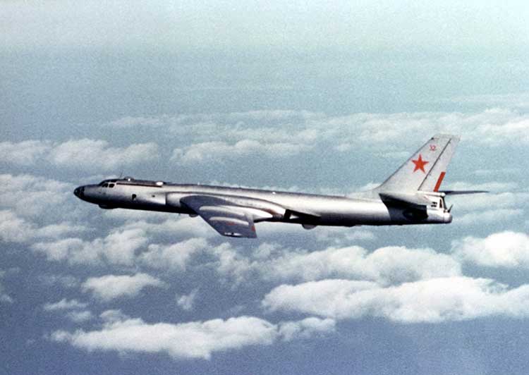
Let’s go back to the Cold War era, at a time when Soviet and Western states were continuously battling for electronic warfare (EW) superiority. In the early to mid-Cold War, radar jamming was the name of the game. Soviet aircraft, such as the TU-16 Badger and its derivatives, carried a range of EW equipment, including some very high-power jammers designed to interfere with radar systems.
Figure 1: TU-16 Badger, an important Soviet electronic warfare platform during the Cold War (Photo: Wikipedia)
Fast forward to the latter years of the Cold War, and we reach the era when the U.S. was busy developing the exciting new GPS system. The Department of Defense (DoD) wanted to ensure that a robust and accurate global navigation system was available to the military, and so the Navigation System with Timing and Ranging (NAVSTAR) launched its first satellite in 1978, eventually becoming the fully operational GPS system by 1993.
Magnificent and ground-breaking though it was, it was recognized very early on that GPS relied on very low-power satellite transmissions, and would be vulnerable if someone tried to interfere with it. Given the prevalence of high-power jamming during the still-ongoing Cold War, there was concern that, if an adversary knew about GPS, they could easily render it useless in a given operational area.
And so it was that the CRPA came to the rescue.
Enter the CRPA
Once again, this GPS anti-jam technology finds its roots in the Cold War, and specifically in radar technology, where engineers developed clever ways to ensure their radars could continue to operate in the presence of jamming. Sidelobe cancellation (SLC) was a well-established technique in the radar community, where a received jamming signal could be “cancelled” by combining the outputs of more than one antenna in the right way.
So, it didn’t take long to adapt this radar anti-jam technology to the problem of GPS protection, and the CRPA was born. At this point I must declare a modicum of national pride, as the earliest operational GPS anti-jam unit that I know of was British. The Plessey PA 9800 GPS Anti Jam Unit was built at Roke Manor in 1984, and tested in the U.S. at the Yuma Proving Ground, Arizona, in 1985.
This pioneering technology could defeat up to three simultaneous jammers in the shown configuration, but was modular in construction, allowing further channels to be added for handling higher numbers of jammers. And all of this in 1984, in the UK, for a U.S. military navigation system that wasn’t even fully operational yet. Incredible.
From then until the present day, CRPAs have seen continual interest and development as the technology of choice to protect GPS from jamming. So how do they work?
Theory of operation
A CRPA is attractive, because it doesn’t require you to make any changes to the GPS receiver itself: It simply replaces the existing antenna. CRPAs are generally larger than typical GPS antennas, because they contain a number of antenna elements, and some associated electronics to do the clever stuff.
There’s nothing magical or mystical about the basics of CRPAs: It’s just standard theory from your favorite textbook on adaptive signal processing. But, as ever, the devil is in the detail — how to make them work well in practice is more involved. And as the technology is generally export-controlled, I shall leave out the important in-depth details.
CRPAs work by exploiting spatial diversity; that is, making use of the fact that the desired satellite signals, and the unwanted jamming signals, generally arrive from different directions. In simple terms, you create a spatial filter, one that removes signals that arrive from particular directions, whilst letting through signals from other directions. To achieve this, rather than use a single antenna, we use an array of antenna elements.
Let’s think in simple and intuitive terms about how this works. Take a look at Figure 3. Here we have a primary antenna P, and some auxiliary antennas A1, A2, and so on. A signal arriving from the direction shown impinges on antenna A2, and slightly later it arrives at A1, and later still it arrives at P. For the sake of argument, if the signal is a simple sine wave, you will then find that the output from each antenna is that same sine wave, but with a different phase shift depending on the spatial arrangement of the antennas.
Now, let’s consider what we call the “weights,” which are labeled as w1, w2 and so on. Each of the weights, in this case, is simply a phase shift that we can define. By careful choice of weights, we could choose to make each of the antenna outputs align perfectly in phase, and then, when we sum all the outputs together as shown, we end up with a bigger version of the input signal.
This is what we would like to achieve if the signal was a satellite. We “steer” maximum overall antenna gain towards that satellite. This is typically what is meant when we refer to “beamforming;” It means steering maximum antenna gain towards a satellite.
Conversely, we could also choose the weights to have the opposite effect: to minimize or completely cancel out the signal. This, of course, is what we would like to do if the signal was a jammer, and is referred to as “nulling” or “null-steering.”
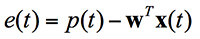
Figure 3. Adaptive antenna basics.How do we determine what those weights should be? Well, this is where your standard theory in adaptive signal processing comes in. Let’s say the objective is to minimize the jamming power out of the antenna. We can write the output power of the adaptive antenna as:
Figure: Michael Jones
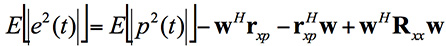
The average output power can be found by taking expectations:
Figure: Michael Jones
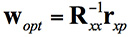
Taking the minimum and rearranging this leads to the well-known Wiener equation:
Figure: Michael Jones
This Wiener equation is the one to remember. It says that the optimum weights can be found by taking the inverse of the data covariance matrix, and multiplying it by the vector of cross correlations between the primary and auxiliary antennas. As in any adaptive signal processing problem, a simple way to solve the Weiner equation and get the weights might be to use your favorite gradient descent algorithm, such as least mean squares (LMS):
Figure: Michael Jones
However, a solution using this approach does have its problems, for reasons beyond the scope of this article. The mathematics of beamforming are also bit more involved, so I’ll leave that out here.
Rather than the grossly simplified diagram used here, most decent CRPAs also use a more complex architecture based on space-time adaptive processing (STAP) or space-frequency adaptive processing (SFAP). This generally allows much higher levels of jammer cancellation against a wider range of threats.
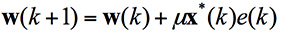
To finish off this whirlwind section on CRPA basics, let’s see what some example antenna gain patterns might look like. In the figures below, the blue line represents the direction of arrival of a GNSS satellite signal, whilst the red lines indicate the direction of arrival of a jammer. In the first diagram we have a single jamming signal: the antenna gain pattern is a nice hemisphere, as we would generally like, but there is a nice deep null in the direction of the jammer. Moving on to the next diagram, we can see the effect of having three simultaneous jammers on the same CRPA: again we have nice deep nulls in the direction of each jammer, but we are starting to lose more of the sky, and we may start to lose the odd satellite as a consequence. Finally, we have an example of beamforming on a single satellite, whilst nulling out a jamming source.
Again, it’s beyond the scope of this article, but the layout of the antenna elements plays an enormously important part in the performance and behavior of the CRPA.
Figure 4. Illustrative beam patterns of a CRPA antenna in the presence of jamming. (Figure: Michael Jones)Figure 4: Illustrative beam patterns of a CRPA antenna in the presence of jamming (Figure: Michael Jones)
Operational Anti-Jam Units
With some images courtesy of my friends at Raytheon, let’s look at a few examples of deployed military CRPA hardware over the years.
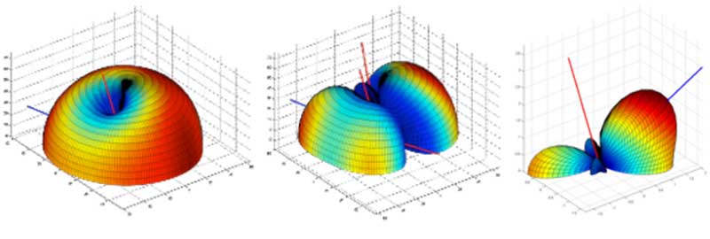
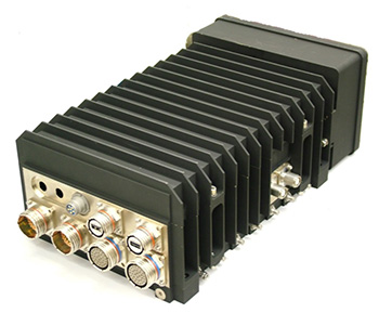
The GAS-1 system entered service in the U.S. in 1997, as a replacement for the earlier AE-1 (1990 to 1996). The CRPA is composed of two parts: the antenna array, which is a seven-element layout, and the antenna electronics as a separate box. The GAS-1 was incredibly successful and became the de facto standard anti-jam technology, fitted to air and sea platforms around the world. Even today, 20 years after its launch, it continues to be fitted to many platforms.
Figure 5. GAS-1 CRPA. (Photo: Raytheon)
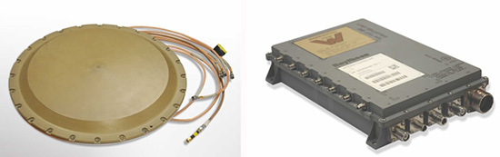
By the late 1990s and early 2000s, the Navigation Warfare (NAVWAR) program was in full swing, and the military was looking for enhanced protection against evolving jamming threats. The U.S. initiated a program called Advanced Digital Antenna Production (ADAP). The ADAP product, launched in 2006, was a direct form-fit replacement for the analog GAS-1 system, and introduced a number of advanced features. Most notably, the ADAP simultaneously protects both the L1 and L2 frequency bands, and utilizes STAP processing to achieve high levels of wideband jammer cancellation.
Figure 6. ADAP Digital CRPA. (Photo: Raytheon)
In parallel with the ADAP development, the Digital Antenna Control Unit (DACU) was different in a number of ways. Firstly, it was a true beamforming solution, allowing simultaneous antenna beams to be steered toward satellites, whilst simultaneously nulling out jammers.
Secondly, it was tightly integrated with the GPS receiver, with the GPS receiver hardware located in the same unit.
Thirdly, the DACU was able to perform a number of other advanced functions, such as direction-finding of interference sources. Interestingly, the DACU was used to help locate the source of the interference at the notorious Newark airport jamming incident in 2009.
By the mid-2000s, CRPA electronics were pretty mature and well-understood. The electronics had been miniaturized, and pretty much everything was put onto a single chip. But the physical size of the antennas persisted as a problem for some platforms requiring low size, weight and power (SWAP).
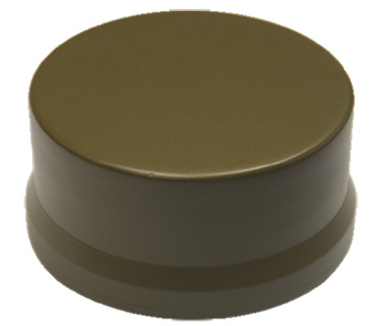
The Landshield, launched in 2014, was a step-change in CRPA technology. Not just because it was a small and fully self-contained unit (about the size of a hockey puck), but because it was the world’s first CRPA to include true anti-spoofing capability.
Figure 8. Landshield Advanced CRPA with Anti-Spoof Technology. (Photo: Raytheon)
Blurring the lines between military and civilian
Going back a few years, the military was heavily focused on CRPAs and anti-jam techniques in general. Military GPS receivers had been developed and deployed, and the question was how they could retrofit robustness to them. At the same time, the commercial world was heavily focused on mass-market GPS receivers — reducing cost, increasing performance — with little care about jamming.
If you’d talked to me five or six years ago, I would have said the military sector is 20 years ahead of the commercial sector in anti-jam technology, and the commercial sector is 20 years ahead of the military sector in receiver technology.
This assertion holds far less true these days; the lines of separation are much more blurred. The military is learning from the commercial world, embracing COTS, and developing new GNSS receivers. Conversely, civilian applications are now much more concerned with jamming, leading to the adoption of low-cost CRPAs in non-military applications.
The future of the CRPA
Where will CRPA technology go from here? We’ve already seen that the latest generation of CRPAs now performs anti-spoofing, as well as anti-jamming. But there is plenty more to see yet.
Although the core technology behind CRPAs is now mature, the trend for the future will be about “doing more with less.” CRPA technology will become more of a multi-function system. Military platforms need to cut down on the number of separate systems they install, and so CRPAs are likely to become multi-functional, performing situational awareness and signals intelligence.
As antenna technology progresses, we will likely see protected navigation solutions utilizing the same hardware as communication systems and radar systems, providing CESM and RESM functions, and being part of an integrated electronic warfare suite. And conformal antennas will see a resurgence of interest for complex and space-constrained platforms.
Topcon Positioning Group has released a new modular GNSS receiver system, the MR-2. The system combines all current and planned constellation tracking with a comprehensive set of communication interfaces to service any precision application requiring high-performance real-time kinematic (RTK) positioning and heading determination.
Topcon MR-2 GNSS receiver. Photo: Topcon
The MR-2 can perform as a mobile RTK base station, marine navigation receiver, mobile mapping device and as a GNSS receiver for agricultural, industrial, military or construction applications.
“The MR-2 delivers navigation support for a wide-range of applications,” says Jason Hallett, vice president of Topcon global product management. “It is an ideal component for OEMs (original equipment manufacturers) needing a custom, high-accuracy modular design for easy integration.”
“The MR-2 is also designed as a ‘future-proof’ system,” Hallett says, “meaning it tracks all current and planned constellations, making it a smart investment in the expanding GNSS environment.”
The unit housing is water and dust-proof and built to withstand harsh environments with superior vibration and shock tolerances, he adds.
Using Topcon HD2 heading determination technology, the MR-2’s dual antennas compute high-performance heading and inclination determination alongside the RTK positioning engine for precise navigation and guidance applications.
“The MR-2 also provides a variety of communication interfaces such as Ethernet, serial, and CAN, allowing for easy integration into any application,” Hallett says.
The system also offers best-in-class multipath rejection, and using Topcon Quartz Lock Loop technology can operate without disturbances in high-vibration environments.
I have mixed emotions as I write this column. Delighted, absolutely, to be given the opportunity to write for GPS World on topics that I am so passionate about; but also sad that we will not see any more articles from Don Jewell, whose excellent columns I followed so religiously over the years. I never had the opportunity to meet Don personally but, to me, he is irreplaceable. But let’s talk about the changing face of defense positioning, navigation and timing (PNT) — not in the editorial sense, but in the technology sense.
As we all know, PNT and GPS are no longer synonymous. With a host of innovative technologies on the horizon, PNT is about so much more than GPS these days, and the military knows it. Sure, GPS has been the workhorse of PNT for many years, and it’s not going anywhere anytime soon. I’ll be clear on that: GPS is not going anywhere. But it’s not a complete solution either.
Let me paraphrase what a friend in the infantry tells me, by saying GPS is a 60 percent solution to their navigation needs. What does that mean? Well, it goes something like this:
60 percent of the time: GPS is great, it does what we need.
20 percent of the time: We are indoors or underground, and GPS is simply not available.
15 percent of the time: We’re in an urban canyon. GPS availability is intermittent, and the accuracy is poor.
4 percent of the time: We’re in forests or dense vegetation, and GPS is sporadic.
1 percent of the time: GPS is jammed.
You can argue the numbers depending on the mission, but you get the idea. What, then, is the answer for the soldier? Well, first things first: We don’t want to reinvent the good 60 percent so, once again, GPS is here to stay. The question is how do we push past that 60 percent figure and get ourselves closer to 100 percent? Let’s go from the bottom up, and address GPS jamming.
Overcoming interference
The classic solution to jamming is an adaptive antenna, also known as a controlled radiation pattern antenna (CRPA). More on this another time but, for now, suffice it to say that CRPAs are a well-understood and mature technology, and can offer very high levels of jamming resistance.
The often-cited disadvantage of a CRPA antenna is its size, weight and power: As CRPAs employ multiple antenna elements, they are inherently larger and heavier. The electronics can pretty much be covered by a single chip these days, leaving the antennas themselves as the problematic aspect, but advances in antenna technology have also made big hurdles.
For airborne platforms, conformal antennas designed as part of the structure or fuselage can be used; whilst for the dismounted soldier, the trend is towards wearables, where the antennas may be an inherent part of the clothing or helmet design.
Aside from adaptive antennas there are a whole host of other techniques in your anti-jam kit bag, including receiver-based techniques.
It’s a numbers game
For forests and urban canyons, this is where multi-frequency multi-GNSS comes into its own. It really is a numbers game: The more constellations you use, the more satellites you can choose from, and the greater your chances of seeing enough satellites to derive a reasonable navigation solution. You also have more options for mitigating the effects of multipath and other errors.
Of course, this gives rise to a potentially difficult question for some governments: In defense applications, do you want to rely on foreign GNSS constellations as part of your PNT solution? The attitude here depends on your own country’s policy and a trade-off of perceived gains against perceived threats. The UK, for example, has chosen to embrace all available constellations and frequencies in future military navigation systems.
That’s probably about as far as GNSS gets you, because now we’re looking at the 20 percent of the time where the user is indoors or underground. In other words, environments where GNSS simply isn’t available. This 20 percent is perhaps more tricky to address, and is the realm of alternative and complementary PNT technologies.
Beyond GNSS
Fusing different sensor modalities to create a combined navigation solution is anything but a new idea. The benefits of combining GPS with an inertial sensor were recognized a long time ago, and this classic pairing continues to be the subject of research today.
The two technologies are highly complementary in various ways: GNSS offers absolute position, low short-term accuracy, and high long-term accuracy. On the other hand, an inertial sensor offers the opposite: relative position, high short-term accuracy, and low long-term accuracy. It’s a match made in heaven.
But whilst GNSS plus inertial may be a good choice for, say, airborne platforms, it doesn’t solve the in-building and underground problem. Without GNSS, you need something else.
Indoor navigation has been one of the hottest research topics of recent times, but there are really two types of indoor scenario: the first is when you’re in a shopping mall or airport. You can use an inertial sensor, Wi-Fi, mobile base stations, and various other bits of infrastructure to help you navigate.
The second scenario is the military one: You’re in an unfamiliar enemy compound or underground tunnel complex. In this case, there is no GNSS, no Wi-Fi, no mobile communications; and, for navigation, you can only really rely on the sensors you bring with you.
So what other sensor works underground, and complements inertial?
Visual/inertial integration
Visual odometry is an established, yet often overlooked, navigation technology that is undergoing a resurgence of interest, in both military and civilian applications. In simple terms, visual odometry uses sequential camera images to determine motion in a six degrees of freedom reference frame. Using either single or multiple cameras a platform can estimate both its 3D position and orientation, providing much the same information as an inertial sensor — but with a few added benefits.
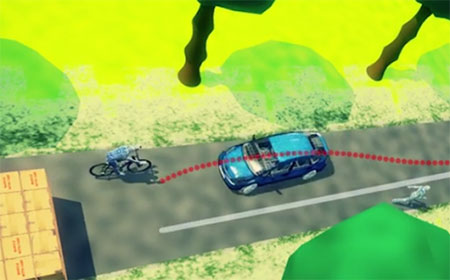
Visual/inertial sensing allows 3D reconstruction of a road incident. (Screenshot: Roke)
Because cameras and associated vision-processing algorithms are capable of detecting corners and features, a 3D model of the environment in which the soldier is operating can also be built up. In other words, we can perform simultaneous localization and mapping (SLAM).
But like any navigation technology, visual odometry has its limitations. It likes well-defined features in the environment, such as corners, but can get confused by moving objects like trees and clouds. Its performance also depends on factors such as the quality of the camera and lens, and how well the system is calibrated. Like an inertial sensor, it provides a relative positioning solution and is subject to accumulation of errors over time. It’s a great technique, but it really comes into its own when combined with another navigation sensor, such as an inertial unit.
And it’s not just the military guys who are taking advantage of visual/inertial integration. Just take a look at Google’s Tango project, or what Qualcomm is doing, or Roke’s black box for driverless cars, to name but a few examples.
Bringing it all together
Over the course of the last decade or two, the operational landscape for soldiers has changed significantly, with far greater focus on urban warfare. The military realized some years ago that the answer to robust navigation for dismounted soldiers was going to require a range of sensor modalities: no single navigation technology is ideal in all environments. That’s why this has been the focus of so many defense programs of recent years.
By way of example, the UK Ministry of Defence (MoD) initiated a research program in 2013 called Dismounted Close Combat Sensors (DCCS). The contract addressed a range of soldier capabilities, one of which was the ability to provide reliable soldier position and orientation in all environments.
The DCCS programme evaluated a whole bunch of technologies, but eventually converged to an integration of three primary sensors: multi-constellation GNSS, a low-cost inertial measurement unit (IMU) and a video camera. The single monocular video camera was used to strap down the IMU, in a very tightly-coupled system. It makes sense: when GNSS is available, use it. When GNSS isn’t available, the integrated visual/inertial navigation sensor continues to provide both location and orientation for the duration of the mission. As it should be for a tightly integrated navigation system, the performance of the combined system outperforms any individual sensor in isolation.
Whilst integrated sensor systems enable our soldiers to position, orientate and navigate themselves, the performance of individual sensors continues to be pushed to new limits. Inertial technology is advancing all the time, and defense is again pushing the boundaries. Take a look at what DARPA is up to, as an example.
The missing ‘T’
Haven’t we missed something? Ah yes, there’s a “T” in PNT. So whilst there would seem to be various options for achieving a robust positioning and navigation solution, we mustn’t forget precise timing for those applications that need it. Quantum technology is flavor of the month here and, once more, the defense agencies are furthering developments: DARPA with its ACES program, and MOD/DSTL via the Quantum Technology Program, to illustrate just a couple of examples.
So whilst GPS will continue to remain the workhorse, defense PNT is migrating from GPS-only to being a many-faced beast. And I haven’t even gotten started on pseudolites, signals of opportunity, eLoran, and cooperative navigation.
The future of defense PNT looks pretty good to me.
The U.S. Defense Advanced Research Projects Agency (DARPA) has awarded HRL Laboratories LLC $4.3 million to develop vibration- and shock-tolerant inertial sensor technology that enables future system accuracy needs without using GPS.
Positioning, navigation and timing are key to ensuring the location accuracy critical to the success of modern military missions. Today’s military systems typically rely on GPS to ensure position accuracy. While GPS provides sub-meter accuracy in optimal conditions, the signal is often lost or degraded due to natural interference or malicious jamming.
“The ATLAS project will deliver a comprehensive approach to breaking performance and cost, size, weight and power barriers in inertial sensor technology that prevent robust, GPS-independent, military positioning, navigation and guidance,” said Logan Sorenson, principal investigator and research staff member in HRL’s Sensors and Materials Laboratory.
ATLAS will combine intimate locking of a micro-electro-mechanical systems (MEMS) Coriolis Vibratory Gyroscope (CVG) sensor with an atomically stable frequency reference in order to exploit the intrinsic accuracy of the atomic hyperfine transition frequency.
“The engineering challenge lies in developing a system architecture to transfer the stability from the atomic reference to the CVG sensor without introducing unintended noise,” Sorenson said. “We are very excited to explore this novel approach to addressing long-standing precision navigation need faced by the U.S. military.”
HRL Laboratories is located in Malibu, California. It is a corporate research-and-development laboratory owned by The Boeing Company and General Motors specializing in research into sensors and materials, information and systems sciences, applied electromagnetics, and microelectronics. HRL provides custom research and development and performs additional R&D contract services for its LLC member companies, the U.S. government, and other commercial companies.
GPS-enabled devices render large amount of assistance to a country’s armed forces on battlefields. In the modern-day scenario of combat, the need to be technically advanced and the ability to achieve precision strike with minimum self-loss are taking center stage.
This has resulted in greater use of GPS-guided devices and weapons by soldiers, which are considered in a new report by Research and Markets.
In Global Military GPS Device Market 2016-2020, analysts forecast the global military GPS device market to grow at a compound annual growth rate (CAGR) of 3.69 percent between 2016 and 2020.
The report covers the present scenario and the growth prospects of the global military GPS device market for 2016 to 2020. To calculate the market size, the report considers the expenditure of each of the three regions (Americas, EMEA and APAC) to acquire these military GPS devices for enhanced performance of warfighters.
The report has been prepared based on an in-depth market analysis with inputs from industry experts. It covers the market landscape and its growth prospects over the coming years.
The report also includes a discussion of the key vendors operating in this market.
Key questions answered in the report include:
What will the market size be in 2020 and what will the growth rate be?
What are the key market trends?
What is driving this market?
What are the challenges to market growth?
Who are the key vendors in this market space?
What are the market opportunities and threats faced by the key vendors?
What are the strengths and weaknesses of the key vendors?
Companies mentioned include:
BAE Systems
Lockheed Martin
Northrop Grumman
Raytheon
Rockwell Collins
Garmin
Harris
Thales
Buyers can request one free hour of the analyst’s time when purchasing thye market report. Details are provided within the report.
Soldier-borne sensors, leader-follower cargo-hauling technology and tiny, handheld unmanned aircraft are in the forefront of new technologies planned for U.S. warfighters, according to Maj. Gen. Robert M. “Bo” Dyess. The deputy director of the U.S. Army Capability Integration Center told AUVSI’s Unmanned Systems Defense keynote audience that developing tools and systems demanded by soldiers is key. He cited a recent demonstration exercise, in which soldiers responded enthusiastically to small, backpackable UAS that would let them see over the next hill or fence.
The Army is also developing autonomous ground systems including an unmanned combat vehicle, fully autonomous convoy operations and swarming unmanned aircraft. Autonomous weapons are seen as key in combatting both relatively low-tech guerilla and militia groups as well as high-tech “near-peer” combatants from organized industrial powers. A contested electromagnetic spectrum is emerging as a critical battlefield in the contemporary and future warscape, Dyess said. Cyberspace, racked by fundamental threats of spoofing, jamming and hacking, becomes the new killing ground.
Shad Reese, Tactical Warfare Systems, Unmanned Vehicles coordinator for the Office of the Undersecretary of Defense, said DoD is elaborating a new unmanned systems roadmap, which should be published in the first quarter of 2017. The roadmap will cover the period 2016-2041.
Reese said that a key aspect of the new roadmap is swarming technology, although at present there is little work underway in industry to support this. “Everyone and their mom is talking about swarming, but if you step back and look at what’s going on in industry, there are no real players in industry working on swarming.” Some work is underway in academia, but “we would like to have commercially available swarming technology.”
The Army’s squad mission support transport robot (SMET).
Army’s Ground Robots
The Army has put a robotic vehicle, the squad mission support transport robot (SMET), designed to carry heavy loads for troops, into an accelerated acquisition program. SMET is a 1,000-lb. tracked or wheeled platform carrying rucksacks, water or ammunition. A SMET version was recently tested in Afghanistan.
An Army spokesperson said the SMET has also been chosen as a pilot program a new way to do acquisitions that could shave time off development and fielding of new technologies, with industry involved from the start in specifications and requirements.
Swarms
Hordes of flying, thinking armed robots that autonomously coordinate amongst themselves, altering attack strategies in mid-mission and pushing through to strike targets kamikaze-style, are also seen as critical to future combat. The Air Force Research Laboratory calls the tactical weapons “distributed collaborative systems.”
Three drones work together to beam back information about an enemy’s location, and blocks their radar signals. (Image: DARPA)
The Air Force seeks to put “that next level of decision making and capability on the platform. Not only can it maintain itself, but it can work other parts of the team, whether those be airmen, or whether those be other machines to perform a mission task.”
Swarming micro-drones can be “really fast, really resistant. They can fly through heavy winds and be kicked out the back of a fighter jet moving at Mach 0.9, like they did during an operational exercise in Alaska last year, or they can be thrown into the air by a soldier in the middle of the Iraqi desert.”
“Swarming is a way to gain the effect of greater intelligence without each individual unit needing to be intelligent,” added one strategist. Last year Gen. Ellen Pawlikowski, commander of the Air Force Material Command, called swarming drones “very much a game-changing reality for our Air Force in the future.”
One consultant added that a human operator may not be able to compete with a fully autonomous system that identifies, analyzes and geolocates a target, especially in such a scenario where the swarm is moving rapidly. “The power and the sheer speed of execution would give them a huge advantage over their adversaries.”
Kristen Kearns, autonomy portfolio lead at AFRL, said that a major challenge with any autonomous system is verifying and validating that the decisions it is making are correct. Trust, or “verification and validation,” becomes paramount with artificial intelligence, Kearns added. “How do we assure safe and effective operations when we put decision making in the platforms?”
Steve Walker, deputy director of DARPA, said his agency has been working on developing battle management systems with a blend of manned and unmanned vehicles. “You have humans and unmanned systems and you need data fused together quickly and things are happening fast and you don’t want to overload the human with all that information. … You want to give him or her exactly what he needs to make a decision and have all these distributed effects work together,” he said.
One official noted the presence of many YouTube videos demonstrating robots flying, sailing or moving in formation. “It’s a good illustration of how so much of the advancement in this space is happening outside the defense world.”
The Spectratime Force 2020 Rubidium clock is designed for the defense market.
Spectratime, a provider of high precision atomic clocks and a business of the Orolia Group, has launched the Force 2020.
The Force 2020 is a rugged, anti-vibration, GPS/GNSS-lockable, ultra-low-noise Rubidium atomic clock for highly dynamic defense platform applications.
According to Pascal Rochat, managing director of Spectratime, “Next-generation defense airborne radars, drones, helicopters, secure shipboard and radio communications systems use high K-band frequencies which require ultralow noise performance. In tactical missions, ultra-low-noise performance can only be minimally degraded during exposure to dynamic vibration and high-g environments to maintain the integrity of the battlefield systems. Spectratime’s Force-2020 rubidium atomic oscillator is perfect for such critical applications, and thus we are currently working with large defense contractors to integrate our new product into their highly dynamic defense platform systems.”
Product features
Output frequency up to 500 MHz
Can use the patented SmarTiming+ technology, disciplining an external SAASM or a non-SAAMS GPS or GNSS 1PPS reference up to 100,000 seconds with an auto-adaptive loop time operating at 1-ns resolution
State-of-the-art frequency and timing signal stability performance
Integration of an ultra-low-noise OCXO oscillator with optional low g-sensitivity and a single or dual vibration-isolated tray for the OCXO and/or the Rb oscillator to meet various dynamic application requirements.
Talen-X has been given security approval by the GPS Directorate, allowing BroadSim to create and process Y-Code while in a classified environment.
BroadSim is a software-defined GNSS simulator that enables users to easily model true and spoofed signals. BroadSim was developed to simplify advanced jamming and spoofing scenarios with Navigation Warfare (NAVWAR) testing in mind.
BroadSim supports high dynamics, advanced jamming, spoofing and encrypted military codes.
Powered by Skydel’s SDX 1000-Hz software simulator engine, BroadSim can simulate multiple constellations including GPS, GLONASS, Galileo and BeiDou.
Software features:
Capable of generating and simulating multiple signal types
GPS L1, L2 with C/A, P, Y and M
GLONASS G1 and G2
Galileo E1 and E5
BeiDou B1 and B2
Intuitive control using Skydel’s SDX software
Utilizes four RF outputs, each with multiple simultaneous constellations
Generates high-fidelity jamming and interference signals
BroadSim hardware includes a generator and controller with two integrated commercial-off-the-shelf USRP radios, an integrated OctoClock-G with GPS disciplined oscillator, four frequency-independent transmit and receive channels and a UBX-160 RF daughterboard.
A new market report focuses military GPS and GNSS devices. The “Global and Chinese Military GPS/GNSS Devices Industry, 2011-2021 Market Research Report” is an in-depth study on the current state of the industry, with a focus on the Chinese market.
The report provides key statistics on the market status of device manufacturers and is a valuable source of guidance and direction for companies and individuals interested in the industry, according to publisher Wise Guy Reports.
The report provides a basic overview including definitions, classifications, applications and industry chain structure and development policies and plans are discussed as well as manufacturing processes and cost structures.
The report states the global market size (volume and value), and the segment markets by regions, types, applications and companies are also discussed.
Market analysis is provided for major regions including the United States, Europe, China and Japan, and other regions can be added. For each region, market size and end users are analyzed as well as segment markets by types, applications and companies.
The report also focuses on global leading industry players with company profiles, product picture and specifications, sales, market share and contact information. Industry development trends and marketing channels are analyzed.
Finally, the feasibility of new investment projects is assessed, and overall research conclusions are offered.
In a word, the report provides major statistics on the state of the industry and is a valuable source of guidance and direction for companies and individuals interested in the market.
Integrated with images and dense distance measurements from a range camera using active illumination, inertial navigation produces real-time results on a tablet computer. Experiments demonstrate that the system provides good positioning and mapping performance in a range of indoor environments, including darkness and smoke.
Soldier with prototype system mounted on tactical vest.
Positioning and mapping abilities for indoor environments can speed search and rescue, keep firefighters from getting lost, and help a commander track soldiers searching a building. Accurate results from these environments increase personnel safety in unknown, dangerous environments and can also facilitate remote control of unmanned ground vehicles (UGVs).
A new iteration in the Chameleon family of positioning systems that we have developed, the Tiger Chameleon, combines an inertial measurement unit (IMU) with an active camera that measures distances using modulated laser light. This type of camera provides dense and accurate distance measurements, and has the added advantage of working well in darkness.
The main goal of the Chameleon systems is to provide soldiers and first responders with position information and approximate overview maps, preferably without affecting their operating procedure. The Tiger Chameleon does not require any infrastructure, such as visual markers or radio beacons. Positioning and mapping results are computed in real time based on data from the IMU and the active camera, and wirelessly transmitted to a visualization interface running on a tablet computer or smartphone.
Sensors and Hardware
In initial experiments, the Tiger Chameleon’s components are enclosed in a wooden box which can be mounted on a soldier’s tactical vest. FIGURE 1gives a schematic overview.
FIGURE 1. Schematic overview of how the components are connected.
Image Sensor. The image sensor includes two cameras: one high-resolution visual camera and one lower-resolution depth sensor. The latter uses a modulated near-infrared (NIR) light source and a special type of sensor to measure distance. Essentially, each pixel is divided into two halves, one of which integrates incoming light when the light source is turned on, while the other integrates light when it is turned off. If the light hitting a pixel has bounced off an object located close to the sensor, almost all light will be integrated by the first half of the pixel. If the object is moved further away, it will take longer for the light to return, and hence more light will be integrated by the second half of the pixel.
In addition to measuring the depth of the scene, the NIR camera provides an intensity image where the value of each pixel is determined by the total amount of light hitting the two pixel halves. The intensity image is similar to an ordinary visual image. Unlike an image from a passive camera, however, it is largely independent of ambient light, since it mostly measures reflected light from the illuminator. Hence, both the intensity and the depth images are available even in completely dark or obscured environments. Coming from the same sensor, the intensity and depth images are perfectly registered to each other. Images are produced at 30 Hz.
The high-resolution visual camera is not used by this prototype.
Inertial Sensor. The IMU provides calibrated measurements of acceleration and angular velocity at 400 Hz. The sensor itself does not perform any inertial navigation or attitude estimation. Since we fuse the inertial data with image-based features for navigation, however, the basic acceleration and angular velocity measurements are more useful in our application than pre-filtered position or orientation estimates. The sensor measures acceleration up to 5 g, and angular velocity up to 1,000 degrees/ second, since relatively high-dynamic motion is common in the intended application. The IMU also contains a magnetometer and a barometer, but these are not used since air pressure and magnetic fields are not always reliable for navigation indoors.
Algorithms
The positioning algorithm is based on EKF-SLAM, simultaneous localization and mapping (SLAM) implemented as an extended Kalman filter (EKF). The EKF fuses data from the IMU (three-dimensional accelerations and angular velocities) with image data, according to the uncertainties of the different types of data. It tracks the system state, composed of the position, velocity and orientation of the system, the IMU biases (slowly varying offsets in the acceleration and angular velocity measurements), and the positions of a number of landmarks in the images.
The landmarks are points observed in the images, which are used for navigation. These are chosen to be points which are recognizable, well-defined and stationary. This essentially means that it should be easy to recognize a landmark when it appears in a new image, and that the image coordinates of a landmark should be stable in both the horizontal and vertical directions. Thus, corner points are good candidates for landmarks, while line structures in an image are not. The world coordinates of a landmark should not change over time.
Theoretically, it would be possible to navigate using only IMU data. The system orientation would then be obtained by integrating the angular velocities, while the acceleration (after removing the effect of gravity) would be integrated to obtain the velocity, and double-integrated to obtain the position. Due to the high bias variability and noise of micro-electro-mechanical systems (MEMS) IMUs — the only type sufficiently small, lightweight and inexpensive for use by soldiers or firefighters — this only works for a few seconds before the accumulated error grows to an unacceptable level.
In theory, it would also be possible to navigate using only landmarks extracted from the image sequence. This, however, is also problematic in practice. If the system moves too rapidly, successive images may not share any landmarks at all. Additionally, no landmarks are found in featureless environments. This causes image-only navigation to fail in many realistic scenarios.
By fusing the inertial data with landmark observations, we alleviate most of these problems. While the IMU provides good short-term performance, the image data provides long- term stability. Hence, the IMU can overcome short periods with few or no landmarks, while the image data limits the error growth of the system (assuming that the periods without landmarks are not too long).
FIGURE 2. Overview of the algorithm.
Algorithm Flow. In the data fusion FIGURE 2, potential landmarks are found in an intensity image from the NIR camera, by identifying points that can be well localized. The potential landmarks are found by using an interest-point detector. The visual appearance of a point is represented using the SIFT descriptor. The distance to each potential landmark is determined by using the depth image. Potential landmarks are matched to landmarks that are already tracked by the system, based on a combination of their visual appearance and their coordinates (the spatial distance between the observed points and the predicted image coordinates of the tracked points, and the difference between the predicted and the observed distance to the points).
IMU data is used to predict where tracked points should appear. Pure inertial navigation is relatively accurate in the time interval between successive frames (approximately 30 images per second are processed). Observed points, which match tracked points, are used to update the estimated state (position, velocity and so on). Tracking is started for observed points, which do not match any tracked points unless a predetermined number (30 in the current implementation) of points are already tracked. Points that are tracked but not observed in a number of consecutive image pairs are removed from the point tracker.
Each depth image corresponds to a local point cloud, where points lie on the surfaces of objects in the scene observed by the camera. The intensity of each point can be obtained from the corresponding intensity image. Since the position and orientation of the system are estimated by the SLAM algorithm, these local point clouds can be transformed into a common coordinate system, thereby creating a large point cloud representing the entire environment along the trajectory of the system. This point cloud can either be used as a three dimensional model, or projected onto a horizontal plane for an overview map.
Implementation
To accurately predict where tracked landmarks will appear in a new image, it is important to synchronize the image stream and the inertial data. While the IMU handles this well (it can either trigger, or timestamp the trigger pulse from, a camera), synchronization is potentially difficult when working with consumer hardware such as the the one selected for this prototype. However, while the camera cannot be triggered externally, it does perform internal synchronization between the NIR and the visual cameras, which both run at 30 Hz. (It is unknown to us which camera triggers the other, or if there is a third piece of hardware which triggers both cameras.) Using an oscilloscope, we found that a pulse train at 30 Hz can be accessed at a solder point inside the camera.
This 30 Hz signal is active whenever the camera is powered. It is therefore not possible to synchronize the camera to the IMU using only this signal, since it only indicates that an arbitrary image was acquired at the time of each pulse. To synchronize the sensors, we need to know exactly when each specific image was acquired. Thus, a synchronization pulse, which is only transmitted when image acquisition is enabled, is needed. In addition to the 30-Hz pulse train, a signal that is high only when the cameras are active can also be found inside the camera. We perform a logical AND to combine these signals into the desired synchronization pulse.
We obtain the timestamp of each image from the IMU by connecting the combined synchronization signal to its synchronization input. There is a small delay between the first pulse in the combined signal and the time when the first image is acquired. This was measured by recording inertial data and images while first keeping the system stationary, and then rotating it quickly. Manual inspection of the image sequence and the angular velocities reveals that the delay is approximately 8 intra-frame intervals (0.267 s).
Software. The recording and analysis software are written in C++, and run in real time under Linux. It makes heavy use of multi-threading in order to optimize the computational performance of the algorithms.
The software is divided into two subsystems: one that communicates with the sensors, and one that performs the image analysis and SLAM computations. These subsystems communicate using the Robot Operating System (ROS). There is also a subsystem (or “node” in ROS terminology) for playing back previously recorded data. The playback node publishes the same type of messages as the sensor node, and these nodes can therefore be used interchangeably.
FIGURE 3. Overview of the analysis node. Blue boxes represent threads, while red boxes are queues. Purple boxes are other software components, and the orange and the red/green boxes represent the sensors. Orange, red and green lines represent data from the respective sensors. Black lines represent data based on more than one sensor.
FIGURE 3 shows how data flows through the analysis node. Queues buffer data between the different threads. Incoming images from the recording or playback node are initially put in the image queues for feature extraction. After feature extraction (where the depth image is used to determine the distance to each observed landmark), the resulting image features are stored in the potential landmarks queue. The features are then processed by the EKF-SLAM thread, which also reads from the IMU data queue. The resulting pose estimates (positions and orientations) are sent to the communication module, where they are transmitted to the visualization device. In parallel with this, images are also processed by the rectification and mapping threads, where they are paired with poses from the SLAM algorithm to create map data. The map data is also sent to the communication module. A number of efficient libraries exist for low-level image processing, and also for the linear algebra computations needed by the EKF. The following libraries are used:
VLFeat for finding landmarks and extracting SIFT features
OpenCV for image rectification
Armadillo for high-level math operations
ROS for communication between the subsystems
A modified version of IAI Kinect2 for ROS communication with the sensor
A slightly modified version of Libfreenect for low-level communication with the sensor.
Evaluation
The prototype has been evaluated in a number of experiments, in cooperation with soldiers and first responders. Three experiments are reported here. All were performed during soldier or smoke-diver training. Mapping results in the figures are presented along with estimated soldier and smoke-diver trajectories (bluegreen lines) from the positioning system. The results are evaluated based on the mapping, since the ground truth trajectories are unknown. Positioning is still evaluated implicitly, as inaccurate positioning would cause poor mapping performance such as double or skewed walls, since the mapping is based on estimated camera positions and orientations.
Searching for Biological Hazards. Collection of evidence at a crime scene is commonly performed using a camera, taking numerous pictures of the scene from different positions at different angles and distances. To keep track of all images and where they were captured is cumbersome work, which can easily be automated by integrating the camera with a positioning system.
Several variations of this experiment were performed, all in cooperation with soldiers from the Swedish Armed Forces National CBRN Defence Centre. The main task was to document different areas in the building, to be able to handle any encountered dangerous biological objects in a safe way, and to preserve evidence for later use. If a dangerous object is found, the mapping result from the system could be used to plan how the object should be taken care of and what exit path the soldiers could use to minimize the time being exposed to a dangerous environment.
FIGURE 4. Map estimated by the prototype positioning and mapping system while two soldiers searched for biological hazards. The trajectory is also shown. The grid spacing is two meters.
The photo above an image from the NIR sensor in the prototype system, captured in the building while two soldiers searched for biological hazards. A map estimated by the prototype system appears in FIGURE 4.
For evaluation of the mapping performance, a part of this building was also measured using a highly accurate scanning laser system. FIGURE 5 shows the point clouds from both the Tiger Chameleon (black) and the scanning laser (white). Locally (within a room), the errors are less than 5 centimeters. Over larger distances, heading drift causes larger errors, which are visible as slightly misaligned walls. In this case, there are no significant errors. (The structures that are only visible in the laser scanner data are parts of the ceiling and its supporting beams, which were never observed by the positioning system.)
FIGURE 5. Map produced by the Tiger Chameleon (black) overlaid on reference data (white).
Searching a Building. A group of eight soldiers searched and cleared a part of a building. This required them to move more quickly than in the first experiment, since the building could not be assumed to be safe. Additionally, one or several soldiers often appears in the field of view of the positioning system. We requested the soldier carrying the system to avoid walking too close behind another soldier, to avoid covering the entire field of view. Apart from this, the soldiers were asked to act as they normally would during the exercise.
FIGURE 6 Map estimated while eight soldiers cleared a building.
Positioning and mapping results are shown in FIGURE 6. The map is slightly distorted due to errors in the estimated heading, but still good enough to understand the building layout. The distortion is visible as double walls in the top part of the figure. We believe that most of the errors were caused by the system not being entirely stationary during the sensor initialization at the start of the experiment. No reference map is available for this location. We also performed experiments where the soldiers fired their weapons near the positioning system. This affects the IMU, severely degrading the measurements of acceleration and angular velocity. Hence, the positioning system was not able to present correct position or mapping estimates in these cases.
Smoke-Diver Searching a Building. The smoke-diver experiments indicated how the positioning system performs when used in a smoke-filled environment. During the experiments, the system was exposed to different levels of smoke.
FIGURE 7. Map estimated while a smoke-diver searched a (partly) smoke-filled building. The trajectory is also shown.
Positioning and mapping results from the experiment are shown in FIGURE 7, while FIGURE 8shows the result from the Tiger Chameleon (black) overlaid on reference data from the laser scanner (white). The estimated map is in good agreement with the reference map data, although a heading error affects some walls (bottom right).
All smoke densities affect the image quality from the NIR sensor, since the active illumination is reflected by the smoke particles. In light smoke, the main effect is that the smoke appears as spurious points in the point clouds, eventually ending up in the map, while positioning performance is not significantly affected. Most spurious points were removed by adding the constraint that points very close to the camera are not added to the map, although smoke still causes more interior points to be visible in Figure 7 than in the other maps. The effect on the positioning system increases with the smoke density. In thick smoke, most illumination is reflected, effectively rendering positioning impossible using this type of image sensor.
Discussion
FIGURE 8. Maps from the experiment in smoke. The map produced by the Tiger Chameleon (black) is overlaid on reference data (white).
The current positioning algorithm works well, but over longer experiments its position estimate slowly drifts away from the true position. This is caused by both the inertial sensors and the landmark-based positioning updating the current position estimate only relative to recent estimates. Since landmarks are discarded after not being observed for a short time, no loop closures ever occur. Saving landmarks could solve this in specific scenarios, where landmarks are re-observed after long times, but doing so would increase the computational complexity considerably. Additionally, for landmark-based loop closure to work well, the landmarks would need to be reobserved from approximately the same position, further limiting the scenarios where this could be expected to work well. Ongoing work aims instead at closing loops by recognizing the scene geometry, as represented by the point-cloud models.
When using active illumination, the mapping performance does not depend on texture on walls and other surfaces. This is an advantage compared to passive stereo cameras. Further, active illumination enables positioning and mapping in darkness.
Comparison to Other Systems. The prototype system was not constructed with the purpose of creating high accuracy models of small, detailed environments. Rather, the purpose was to enable soldiers to create approximate maps of entire buildings with minimal impact on their operating procedure. Detailed reconstruction is handled better by other systems, but these have the disadvantage of requiring the user to survey the environment systematically, adapting his or her work methods to the sensor.
SWaP-C and Hardware. Size, weight, power and cost (SWaP-C) are constant issues for soldier equipment. Ideally, the equipment should be disposable: cheap enough to throw away after being used just once, or fit into some type of disposable container.
Since this is a prototype system built for research and demonstration purposes, components with convenient electrical and programming interfaces have been selected. Therefore, the system is considerably larger than a final end-user product would be. In such a product, sensors and computation hardware with similar performance, but considerable smaller size, lower weight and lower power consumption, would be selected instead. Such components are commercially available.
Outdoor/Indoor Use. Though this positioning system is primarily designed for indoor use, seamless transition between indoor and outdoor environments is desired. Ongoing work aims at integrating a GPS receiver to achieve this. Adding GPS would also enable positioning in a georeferenced coordinate system; currently, all results are presented in a local coordinate system defined by the start position and orientation. This requires an algorithm for making robust decisions regarding when GPS measurements should be considered reliable.
Visualization Interface. The visualization interface currently runs on a tablet computer, and is therefore most useful to a commander or group leader who remotely tracks the soldier or firefighter. By adapting the interface to the smaller screen of a smartphone, it would be possible to also give the user access to position and map information.
An important advantage of automatic mapping, according to several users, is the ability to detect hidden spaces in buildings. In certain types of operations, the ability to document a building before leaving it is also considered valuable.
Real-Time Implementation. An interesting aspect of performing all computations in real time is that it effectively precludes tuning of algorithm parameters to individual data sets. When analyzing data offline, this is far too common, and typically overestimates the performance of the system or algorithms. All experiments reported in this article have been performed without any such parameter tuning.
Autonomous or Remote-Controlled Platforms. The system can also be used on an unmanned ground or
aerial vehicle (UGV or UAV). This could be suitable for searching buildings too dangerous to enter. The system would continuously distribute its position and mapping estimates while traveling through the building. This could provide soldiers and rescue teams with a preview of the unknown environment and a possibility to plan their operations in a safer way. Many robotics projects use ROS, which makes integration of the Tiger Chameleon relatively straightforward.
Firing of Weapons. During some experiments, we discovered that the measures of acceleration and angular velocity are affected by close-range gunfire. Relatively long segments of measurements are affected, which makes interpolation of missing values difficult. During these periods, it may be possible to disregard the inertial measurements, resorting to only image-based positioning.
Summary
This prototype system for indoor positioning and mapping, based on inertial navigation and distance measurements using active illumination, does not require any infrastructure or prior knowledge about the environment. The system has been designed for experiments and demonstration purposes, and has been shown to provide good performance in real time in a variety of different indoor environments when carried by potential end users.
Manufacturers
The Tiger Chameleon consists of a Microsoft Kinect v2, an Xsens MTi-10 IMU and a small computer with a mobile Intel i7 CPU.
Acknowledgments
The authors thank the soldiers from South Scania Regiment (P7), Sweden, who participated in the initial tests with the prototype. We also thank the smoke divers from Södertörn Fire Prevention Association, Sweden, for carrying the prototype in smoke-filled environments. Also, we really appreciated the feedback from the Swedish Armed Forces National CBRN Defence Centre during the prototype development. Finally, we acknowledge Hannes Ovrén at Linköping University, Sweden, for improving the Libfreenect library.
The material in this article is based on a technical paper presented at ION/IEEE PLANS 2016.
The ION 2016 Joint Navigation Conference (JNC) advance program is now available online. The JNC, sponsored by the Military Division of the ION, will be held June 6-8 (FOUO U.S. ONLY) at the Dayton Convention Center, Dayton Ohio; and the U.S. ONLY CLASSIFIED sessions will be held June 9 at the Air Force Institute of Technology on Wright-Patterson Air Force Base.
JNC 2016 will be the largest U.S. military positioning, navigation and timing (PNT) conference of the year, with joint service and government participation. Registrants can save $200 on conference registration by booking the hotel first, and entering a valid hotel confirmation number from one of the official conference hotels at the start of the registration process.
JNC 2016 will focus on technical advances in guidance, navigation and control (GN&C) with emphasis on joint development, test and support of affordable GN&C systems, logistics and integration. From an operational perspective, the conference will also focus on advances in battlefield applications of GPS; critical strengths or weaknesses of fielded navigation devices; warfighter PNT requirements and solutions; and navigation warfare.
PLEASE NOTE: Attendance Restricted
Conference attendance for both FOUO U.S. ONLY (June 6-8) and U.S. ONLY CLASSIFIED (June 9) sessions will be screened by the Joint Navigation Warfare Center and will be restricted to U.S. ONLY.