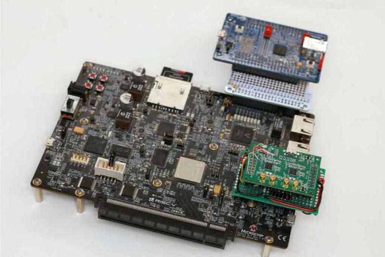
The University of New South Wales has developed an advanced GNSS receiver that can receive signals from GPS and Galileo satellites across multiple frequencies. The Australian Space Agency provided funding for the project via the International Space Investment initiative.
The receiver may play a key part in the future for Australian space missions.
Professor Andrew Dempster, director of the Australian Centre for Space Engineering Research (ACSER), led the development of the receiver and notes that it is an upgrade of Kea, a receiver made in Australia and New Zealand.
“The idea was to take that work (on Kea) and upgrade it for this multi-frequency, multi-system solution,” Professor Dempster said. “We needed to scale up the performance of many of the components on the boards – in particular, where the digital processors and hardware live.”
ACSER aims to have the receiver support upcoming satellite missions. The receiver can provide precise positioning, timing and velocity information. It enables satellites to produce higher quality images from space with better pointing.
Orolia’s Skydel, its GNSS simulation software, can now generate more than 500 simulated satellite signals. This platform is suitable for GNSS users, experts and manufacturers, as well as users needing a low-Earth-orbit-capable simulation system.
Skydel contains a feature that includes multi-constellation and multi-frequency signal generation, remote control from user-defined scripts, and integrated interference generation.
“With more and more customers simulating multipath and jamming scenarios, and the need for more signals in more applications — even beyond traditional simulators — the need for high capacity has never been greater,” said Pierre-Marie Le Veel, Orolia’s simulation product director. “The Skydel engine opens the possibility for users to escalate to more than 1,000 signals and not be limited by hardware design.”
In addition to generating a high channel and satellite count, Skydel can also produce navigation warfare signals without any additional hardware.
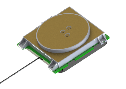
Maxtena has introduced a new multi-frequency antenna shaped for high-precision applications featuring L-band corrections.
Photo: Maxtena
The design will offer simultaneous GNSS reception on L1: GPS, GLONASS, Galileo, Beidou, L2: GPS L2C, Galileo E5B, and GLONASS L3OC, and L5: GPS + L-band corrections in a rugged, compact, and ultra-lightweight form factor. The antenna is well suited for high precision applications. The M9HCT-A-SMA is a great fit for the UAV markets, where high performance and low weight are driving features in antenna selection.
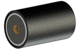
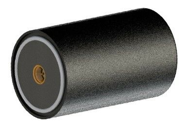
The new rugged active helix antenna is designed and manufactured using automotive grade electronics for GIS, RTK and other GNSS applications.
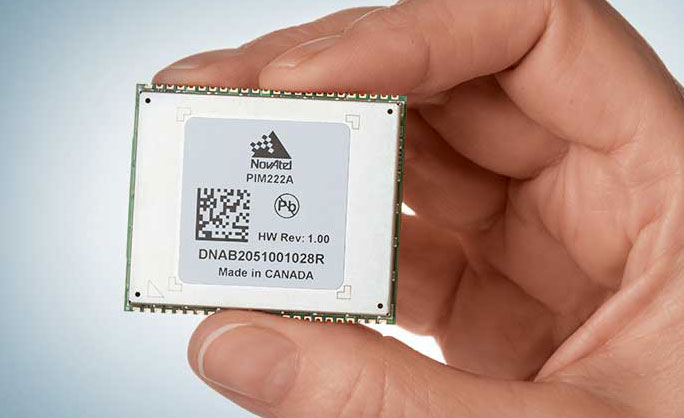
Hexagon | NovAtel has introduced the PIM222A, part of a new family of automotive GNSS positioning products for advanced driver assistance systems (ADAS) and autonomy. The PIM222A harnesses NovAtel’s decades of experience delivering precise positioning in demanding applications for mass deployment in ADAS applications and autonomous vehicles.
Built with automotive-qualified hardware in a package that is easy to integrate, the PIM222A leverages SPAN technology from NovAtel to provide accurate position data in urban environments that challenge GNSS availability. Deeply-coupled GNSS receivers and inertial measurement units (IMUs) ensure continuous availability of position, velocity and attitude, even when satellite signals are briefly blocked.
“I’m excited to introduce the PIM222A, truly the best of both worlds for high-performance GNSS and automotive standards,” said Gordon Heidinger, Segment Manager for Automotive and Safety Critical Systems. “It helps our customers jump-start their development activity for high-precision GNSS, fully supporting performance for all levels of autonomy, ADAS and positioning needs.”
The PIM222A, which was created in collaboration with STMicroelectronics, is a lightweight, power-efficient, solder-down module that maximizes flexibility for integration. The receiver design can be applied to low-, medium- and high-production volumes while retaining a rich array of features, including options such as multi-frequency, multi-constellation, RTK and dual-antenna precision.
The degree of slow-speed and initialization performance is maximized with the dual antenna feature, enabling the best possible positioning performance in all ADAS and autonomous driving situations.
Development kits for the PIM222A are available now for integrators in need of a positioning essentials solution for low- to high-quantity applications.
The M9708CWT-UFL from Maxtena is an active multi-frequency, high-accuracy, GNSS antenna for the L1/L2/L5 GPS, Galileo, Beidou and GLONASS bands. The antenna is designed for applications requiring greater accuracy than L1-only antennas can provide.
The antenna’s excellent radiation pattern, exceptional out-of-band rejection, minimal group delay variation, and low noise figure ensures optimal performance of GNSS systems, according to Maxtena.
The M9708CWT-UFL is designed for applications requiring minimal integration effort or for retrofitting existing products. The antenna is mounted on the inside of the application’s housing, allowing it to be hidden. The antenna element is custom tuned to the enclosure.
Features of the M9708CWT-UFL:
Low profile design
Concurrent GNSS reception on:
L1: GPS, GLONASS, Galileo, Beidou
L2: GPS L2C, Galileo E5B, and GLONASS L3OC
L5: GPS L5, Galileo E5A
Small form factor
GIS, RTK and other high-accuracy GNSS applications
Low power consumption
Minimal phase-center variation over azimuth and elevation
Europe’s EGNOS satnav system has been providing safety-of-life services for 10 years. EGNOS, the European Geostationary Navigation Overlay Service, transmits signals from a duo of satellite transponders in geostationary orbit.
The satellite-based augmentation system (SBAS) gives additional precision to U.S. GPS signals, delivering an average precision of 1.5 meters over European territory, as much as a 10-fold improvement over unaugmented signals. EGNOS also provides confirmation of GPS signal integrity through additional messaging identifying any residual errors.
While the EGNOS Open Service has been in general operation since 2009, EGNOS began its safety-of-life service in March 2011.
The European Space Agency (ESA) designed EGNOS as the European equivalent of the U.S. Wide Area Augmentation System (WAAS), working closely with the European air traffic management agency Eurocontrol. ESA then passed EGNOS to the European GNSS Agency (GSA) to run operationally.
Guiding airliners
EGNOS’s primary customer is aircraft. Without guidance from the ground, pilots using EGNOS can confidently descend in bad weather to 60 meters’ altitude before needing to make visual contact with the tarmac.
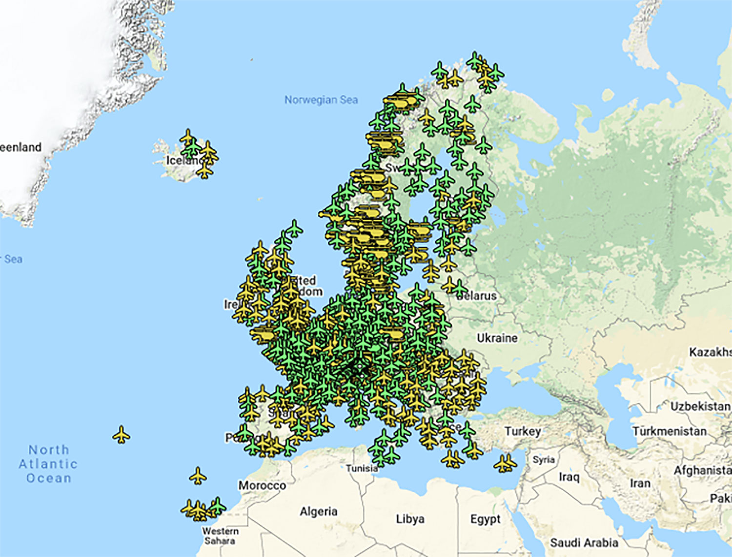
On March 17, 2011, France’s Pau Pyrénées Airport was the first airport to use EGNOS. Today, more than 385 airports and helipads and 60 airlines across Europe use EGNOS-based LPV-200 approaches (short for Localizer Performance with Vertical guidance – 200 feet). The EGNOS service requires no ground equipment, and replaces the radio guidance beamed upward by traditional CAT I instrument landing system (ILS) infrastructure with no decrease in performance.
As of March 2021, more than 385 airports and helipads and 60 airlines across Europe are using EGNOS-based LPV-200 approaches. (Image: ESA)
Serving drones
EGNOS is now being eyed as the enabler of unmanned aerial vehicles (UAVs). The GSA has supported numerous trials of drones equipped with EGNOS as well as Galileo through its EGNSS4RPAS project. Crewed aircraft are expected to be vastly outnumbered in our skies by all kinds of UAVs, employed for everything from weather and environmental monitoring to personalized delivery services.
U-Space is Europe’s program to integrate drones into the airspace. (Image: ESA)
The traditional person-based air traffic control model will need to evolve to accommodate such a shift, based on automated monitoring, traffic management and collision avoidance. In Europe, this highly automated version of air traffic control is termed U-space.
EGNOS’s safety-of-life service is essential to making this happen, moving from today’s situation — where drones are limited to specific air corridors and line-of-sight operations — to let them roam freely but safely in busy airspace and built-up areas.
“The whole idea behind EGNOS’s safety-of-life has been to render satellite navigation sufficiently reliable for any kind of use,” explained Didier Flament, who leads ESA’s EGNOS team. “After 10 years of faultless operations, new applications are becoming plain. Drone flight is one example. EGNOS is also being evaluated for train positioning as well as assisted and autonomous automobile driving.”
EGNOS, the next generation
ESA retains responsibility for the system’s evolution, and the middle of this decade should see the debut of its new generation, EGNOS v3.
“While the current system only works with single-frequency GPS signals, EGNOS v3 will operate on a multi-frequency, multi-constellation basis, able to augment all available satellite signals in both L1 and L5 bands, including Galileo,” Didier said. “The result will be far enhanced performance and reliability.
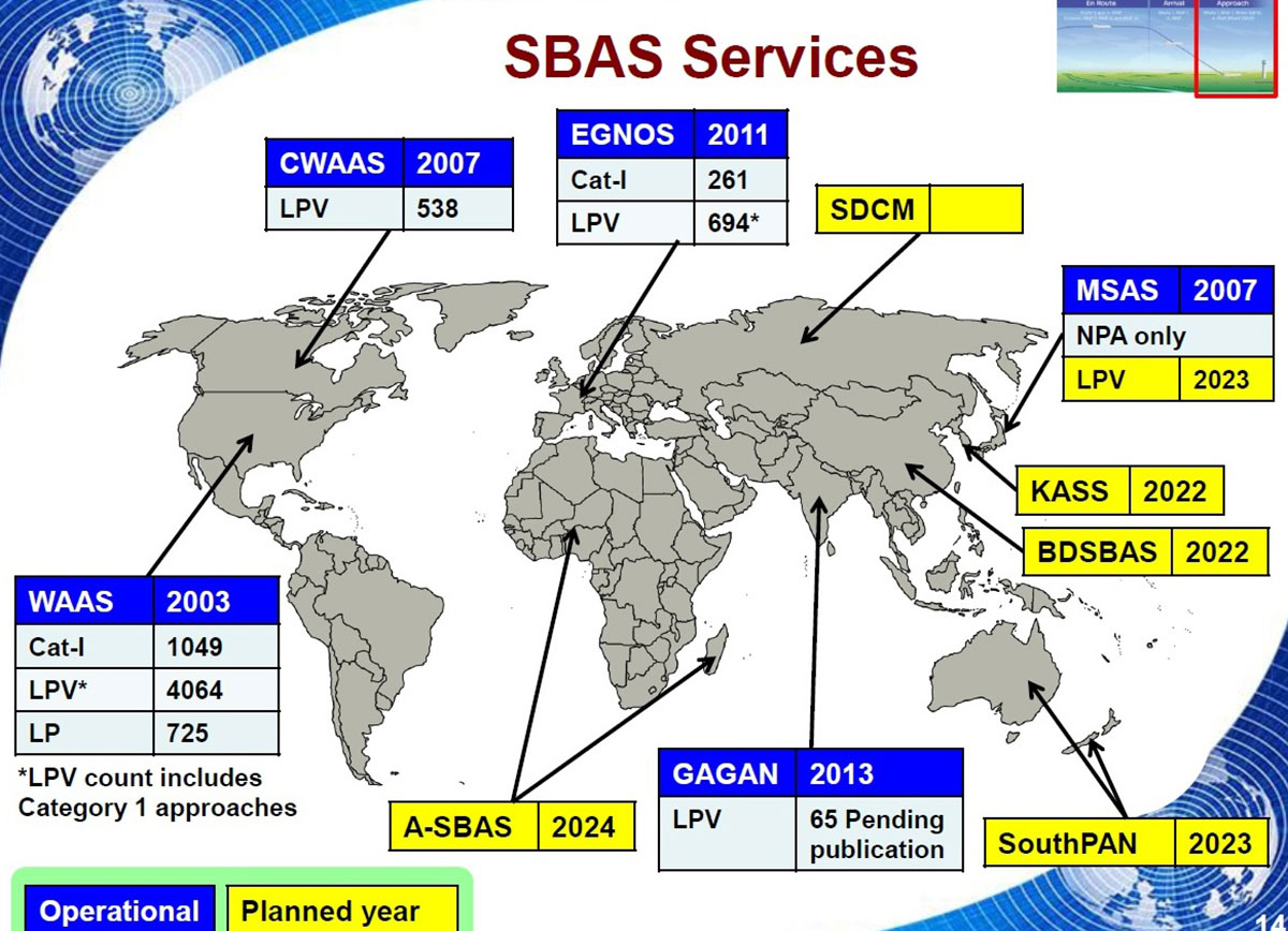
“In addition, we are working with developers of other SBAS around the globe to ensure they stay fully interoperable so for instance EGNOS-equipped aircraft can fly between continents on a seamless basis. Such interoperability, combined with the arrival of the other SBAS systems under development in other regions, will lead to a quasi-global worldwide safety-of-life service coverage in the year 2030.”
Operational and planned satellite-based augmentation systems (SBAS) around the globe. (Image: ESA)
The full GNSS User Technology Report 2020 is available for download. (Cover: GSA)
News from the European GNSS Agency
The European GNSS Agency (GSA) has released its latest GNSS User Technology Report, providing a comprehensive analysis of GNSS trends and developments.
With four GNSS available and more than 100 satellites in operation broadcasting multiple frequencies, the GNSS industry is shifting towards the wide adoption of multifrequency receivers across market segments to meet the diverging user needs of emerging applications.
The report includes contributions from leading GNSS receiver, chipset manufacturers and service providers, and serves as a valuable tool to support planning and decision-making with regards to developing, purchasing and using GNSS technology.
Published biennially since 2016, the User Technology Report has become a point of reference for the GNSS industry, research and policy-makers.
Rapid Evolution
‘’The GNSS industry is evolving at a rapid pace and is shaped by the dynamics of emerging applications and user needs as well as the upgrade of existing and new GNSS and Satellite Based Augmentation Systems (SBAS),” said Rodrigo da Costa, GSA executive director. “The industry has understood the potential of Galileo’s unique features.”
The third edition of the report begins with a chapter devoted to technology trends common to all segments: receiver design, position processing and signal processing. It also discusses protection measures against GNSS jamming and spoofing, such as authentication, including what 5G and other technologies and sensors can do, in combination with GNSS.
With multi-constellation now being the norm, the industry is moving towards the wide adoption of multi-frequency receivers even for usually power- and cost-constrained consumer solutions. The Galileo E5 is becoming the preferred frequency with about 20% of all receiver models in the market already using it.
The report is built around four macro segments defined on the basis of commonalities from a technology point of view:
high volume
safety- and liability-critical
high-accuracy
timing devices and solutions (a new-entry in this edition)
Each chapter starts with the macrosegment characteristics and receiver capabilities, depicts the industry landscape and typical receiver form factor, it then delves into the key current and future drivers and trends, and finishes with the added value of the EGNSS, Galileo and EGNOS, for the macrosegment at stake.
Space Data for Europe
This year editor’s special “Space Data for Europe” sheds light on the role that Copernicus and Galileo play within the European Space Programme in the data management and use, now and in the future. It also provides a vision of major transformations underway within our society and our economy and the benefits expected from this digital transformation, paving the way towards the European Data Strategy and Green Deal.
“Today, Galileo and EGNOS already provide increased capabilities which are being used across a broad range of applications, and are already igniting the next generation of location-based applications. In the future, new services — the Galileo High Accuracy Service (HAS), Galileo Open Service Navigation Message Authentication (OS-NMA) and Commercial Augmentation Service (CAS) — will raise the accuracy and reliability bar even higher, and dramatically enhance positioning, navigation and timing solutions for businesses and citizens.
By bringing insight and understanding into the evolutions of GNSS technology, we are creating opportunities for innovation,” concluded da Costa.
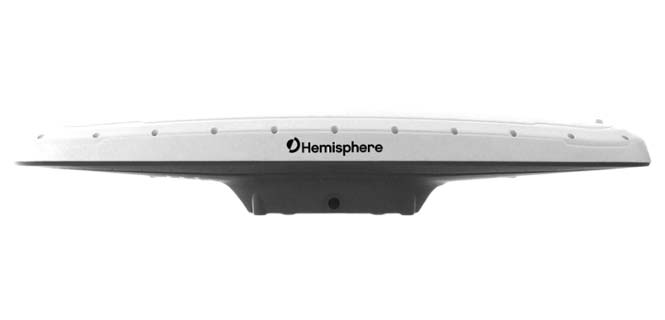
Hemisphere GNSS has released its RTK-enabled Vector V500 smart antenna. The company made the announcement at the Oceanology International conference being held this week in London, U.K.
The V500 supports multi-frequency GPS, GLONASS, BeiDou, Galileo, QZSS and IRNSS (with future firmware upgrade and activation) for simultaneous satellite tracking. The V500 is powered by Hemisphere’s Athena RTK (real-time kinematic) engine and is Atlas L-band capable.
Using Hemisphere’s Eclipse Vector technology, the all-in-one V500 is a complete compass system that offers GNSS-based heading, pitch, roll, heave and RTK positioning, the company said.
The V500 introduces support for Ethernet, Bluetooth and Wi-Fi in addition to NMEA 0183 and NMEA 2000 and offers unmatched ease of installation.
Purpose-built for challenging applications, the V500’s rugged enclosure works reliably in harsh environments and is designed for professional marine applications requiring high-precision heading combined with RTK or Atlas positioning.
The V500 is Hemisphere’s flagship rugged smart antenna. It combines the recently announced Eclipse Vector H328 OEM board with two superior multipath- and noise-rejecting antennas (spaced 50 cm apart) in a single enclosure.
The V500 requires a single power/data cable connection, allowing for fast and reliable installations even in the presence of strong radio transmissions.
According to Hemisphere GNSS, the V500 delivers 0.17 degree heading accuracy along with RTK positioning and Atlas L-band accuracies of up to 8 cm (95 percent).
“The Vector V500 combines our expertise in GNSS, smart antenna design, and our new technology features such as Atlas,” said Lyle Geck, senior product manager at Hemisphere GNSS. “With very competitive RTK performance and the simplicity of installation offered by the all-in-one smart antenna design, it is an incredible product.”
Atlas GNSS Global Correction Service. Atlas is a flexible and scalable GNSS-based global L-band correction service providing robust performance and correction data for GPS, GLONASS and BeiDou, the company said. Atlas delivers correction signals via L-band satellites to provide accuracies ranging from sub-meter to sub-decimeter levels, and leverages approximately 200 reference stations worldwide, providing coverage to virtually the entire globe.
Atlas is available on all Hemisphere Atlas-capable single- and multi-frequency, multi-GNSS hardware and complements third-party GNSS receivers by using Atlas corrections with Hemisphere’s SmartLink and BaseLink capabilities. Atlas creates fast convergence times, and is robust and reliable near wharfs, piers, offshore rigs, cranes and other overhead obstructions.
Atlas Basic provides users of both single- and multi-frequency Atlas-capable hardware the ability to achieve better than SBAS performance anywhere Atlas correction service is available. Atlas Basic offers accuracy of 30 cm (pass-to-pass 95%) to 50 cm (absolute 95%) and offers instantaneous sub-meter accuracy.
The Vector V500 is featured in the Hemisphere GNSS booth (G500) at the Oceanology International exhibition and conference in London, UK, March 13-15. The new V500 will be available soon through Hemisphere’s global dealer network.
Analysis of new Galileo signals at an experimental ground-based augmentation system (GBAS) compares noise and multipath in their performance to GPS L1 and L5. Raw noise and multipath level of the Galileo signals is shown to be smaller than those of GPS. Even after smoothing, Galileo signals perform somewhat better than GPS and are less sensitive to the smoothing time constant.
By Mihaela-Simona Circiu, Michael Felux, German Aerospace Center (DLR), and Sam Pullen, Stanford University
Several ground-based augmentation system (GBAS) stations have become operational in recent years and are used on a regular basis for approach guidance. These include airports at Sydney, Malaga, Frankfurt and Zurich. These stations are so-called GBAS Approach Service Type C (GAST C) stations and support approaches only under CAT-I weather conditions; that is, with a certain minimum visibility. Standards for stations supporting CAT-II/III operations (low visibility or automatic landing, called GAST D), are expected to be agreed upon by the International Civil Aviation Organization (ICAO) later this year. Stations could be commercially available as soon as 2018.
However, for both GAST C and D, the availability of the GBAS approach service can be significantly reduced under active ionospheric conditions. One potential solution is the use of two frequencies and multiple constellations in order to be able to correct for ionospheric impacts, detect and remove any compromised satellites, and improve the overall satellite geometry (and thus the availability) of the system.
A new multi-frequency and multi-constellation (MFMC) GBAS will have different potential error sources and failure modes that have to be considered and bounded. Thus, all performance and integrity assumptions of the existing single-frequency GBAS must be carefully reviewed before they can be applied to an MFMC system. A central element for ensuring the integrity of the estimated position solution is the calculation of protection levels. This is done by modeling all disturbances to the navigation signals in a conservative way and then estimating a bound on the resulting positioning errors that is valid at an allocated integrity risk probability.
One of the parameters that is different for the new signals and must be recharacterized is the residual uncertainty attributed to the corrections from the ground system (σpr_gnd). A method to assess the contribution of residual noise and multipath is by evaluating the B-values in GBAS, which give an estimate of the error contribution from a single reference receiver to a broadcast correction. Independent data samples over at least one day (for GPS) are collected and sorted by elevation angle. Then the mean and standard deviations for each elevation bin are determined.
Here, we evaluate the E1 and E5a signals broadcast by the operational Galileo satellites now in orbit. In the same manner as we did for GPS L5 in earlier research, we determine the σpr_gnd values for these Galileo signals. As for GPS L5, results show a lower level of noise and multipath in unsmoothed pseudorange measurements compared to GPS L1 C/A code.
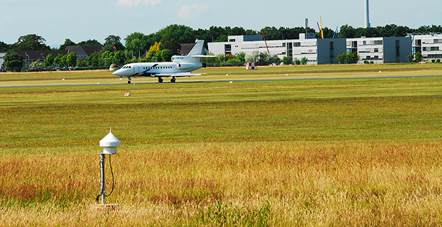
DLR GBAS Facility
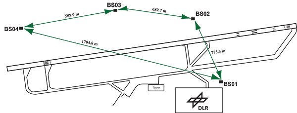
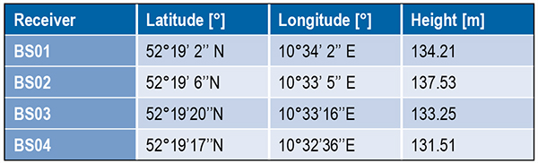
DLR has set up a GBAS prototype at the research airport in Braunschweig (ICAO identifier EDVE) near the DLR research facility there. This ground station has recently been updated and now consists of four GNSS receivers connected to choke ring antennas, which are mounted at heights between 2.5 meters and 7.5 meters above equipment shelters. All four receivers are capable of tracking GPS L5 (in addition to GPS L1 and L2 semi-codeless) and Galileo E1 and E5a signals. Figure 1 gives an overview of the current ground station layout, and Table 1 gives the coordinates of the antennas.
Figure 1. DLR ground facility near Braunschweig Airport, also shown in opening photo at left.Table 1. Ground receiver antenna coordinates.
Smoothing Techniques
The GBAS system corrects for the combined effects of multiple sources of measurement errors that are highly correlated between reference receivers and users, such as satellite clock, ephemeris error, ionospheric delay error, and tropospheric delay error, through the differential corrections broadcast by the GBAS ground subsystem. However, uncorrelated errors such as multipath and receiver noise can make a significant contribution to the remaining differential error. Multipath errors are introduced by the satellite signal reaching the antenna via both the direct path from the satellites and from other paths due to reflection. These errors affect both the ground and the airborne receivers, but are different at each and do not cancel out when differential corrections are applied.
To reduce these errors, GBAS performs carrier smoothing. Smoothing makes use of the less noisy but ambiguous carrier-phase measurements to suppress the noise and multipath from the noisy but unambiguous code measurements.
The current GBAS architecture is based on single-frequency GPS L1 C/A code measurements only. Single-frequency carrier smoothing reduces noise and multipath, but ionospheric disturbances can cause significant differential errors when the ground station and the airborne user are affected by different conditions. With the new available satellites (GPS Block IIF and Galileo) broadcasting in an additional aeronautical band (L5 / E5), this second frequency could be used in GBAS to overcome many current limitations of the single-frequency system.
Dual-frequency techniques have been investigated in previous work. Two dual-frequency smoothing algorithms, Divergence Free (Dfree) and Ionosphere Free (Ifree), have been proposed to mitigate the effect of ionosphere gradients.
The Dfree output removes the temporal ionospheric gradient that affects the single-frequency filter but is still affected by the absolute difference in delay created by spatial gradients. The main advantage of Dfree is that the output noise is similar to that of single-frequency smoothing, since only one single-frequency code measurement is used as the code input (recall that carrier phase noise on both frequencies is small and can be neglected).
Ifree smoothing completely removes the (first-order) effects of ionospheric delay by using ionosphere-free combinations of code and phase measurements from two frequencies as inputs to the smoothing filter. Unlike the Dfree, the Ifree outputs contain the combination of errors from two code measurements. This increases the standard deviation of the differential pseudorange error and thus also of the position solution.
Noise and Multipath in New GNSS Signals
GBAS users compute nominal protection levels (H0) under a fault-free assumption. These protection levels are conservative overbounds of the maximum position error after application of the differential corrections broadcast by the ground system, assuming that no faults or anomalies affect the position solution. In order to compute these error bounds, the total standard deviation of each differentially corrected pseudorange measurements has to be modeled. The standard deviation of the residual uncertainty (σn, for the nth satellite) consists of the root-sum-square of uncertainties introduced by atmospheric effects (ionosphere, troposphere) as well as of the contribution of the ground multipath and noise. In other words, these error components are combined to estimate σn2 as described in the following equation:
(1)
The ground broadcasts a value for σpr_gnd (described later in the section) associated with the pseudorange correction for each satellite. These broadcast values are based on combinations of theoretical models and actual measurements collected from the ground receivers that represent actual system characteristics. Unlike the ground, σpr_air is computed based entirely on a standardized error model. This is mainly to avoid the evaluation of multipath for each receiver and each aircraft during equipment approval.
In addition to the characteristics of nearby signal reflectors, multipath errors are mainly dependent on signal modulation and other signal characteristics (for example, power, chip rate). In earlier research, we showed that the newly available L5 signals broadcast by the GPS Block IIF satellites show better performance in terms of lower noise and multipath. This mainly results from an increased transmitted power and a 10 times higher chip rate on L5 compared to the L1 C/A code signal.
In this work, we extend this evaluation to the new Galileo signals and investigate their impact on a future multi-frequency, multi-constellation GBAS. Characterization of these new signals is based on ground subsystem measurements, since no flight data with GPS L5 or Galileo measurements are available at the moment. We assume that the improvements observed by ground receivers are also applicable to airborne measurements. This assumption will be validated as soon as flight data are available.
The measurements used were collected from the DLR GBAS test bed over 10 days (note that Galileo satellite ground track repeatability is 10 sidereal days) between the December 14 and 23, 2013. In that period, four Galileo and four Block IIF GPS satellites were operational and broadcast signals on both aeronautical bands E1 / L1 and E5a / L5.
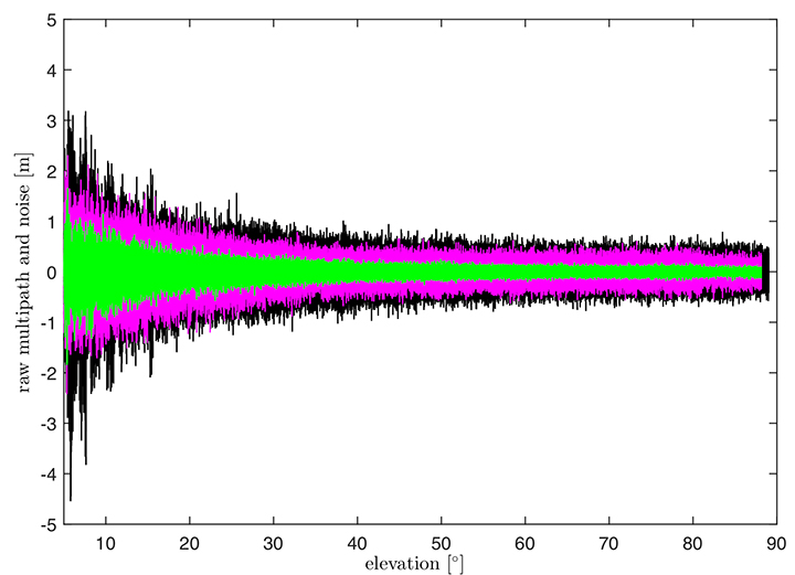
In Figure 2, the suppression of multipath and noise on the Galileo signals can be observed, where the code multipath and noise versus elevation for GPS L1 C/A BSPK(1), Galileo E1 (BOC (1,1)) and Galileo E5a (BPSK(10)) signals are shown. The code multipath and noise was estimated using the linear dual-frequency combination described in equation (2), where MPi represents the code multipath and noise on frequency i, ρi the code measurement, and ϕi,and ϕj represent the carrier-phase measurements on frequencies i and j, respectively. Carrier phase noises are small and can be neglected.
(2)
Figure 2. Raw multipath function of elevation for GPS L1, Galileo E1 (BOC (1,1)) and Galileo E5a (BPSK(10)) signals.
The multipath on the Galileo E1 (BOC(1,1)) signal (the magenta curve) is lower than the GPS L1 C/A (BPSK(1))(black curve), especially for low elevation, where the advantage of the E1 BOC(1,1) is more pronounced. The lower values can be explained by the wider transmission bandwidth on E1 and the structure of the BOC signal. Galileo E5a (green data in Figure 2) again shows a better performance than Galileo E1. This was expected due to the higher chip rate and higher signal power. A comparison of the raw multipath and noise standard deviations for GPS L1, L5 and Galileo E1, E5a signals is presented in Figure 3.
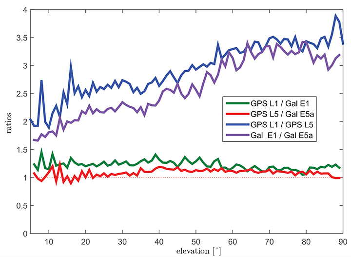
Figure 3. Ratios of the multipath and noise standard deviation function of elevation.
The curves there show the ratios of the standard deviations for each elevation bin. The values for GPS L1 are almost 1.5 times larger than those for Galileo E1 BOC(1,1) (green curve) for elevations below 20°. For high elevations, the ratio approaches 1.0. This corresponds to the observations in the raw multipath plot ( Figure 2). With the same signal modulation and the same chip rate, E5a and L5 have very similar results (red curve), and the ratio stays close to 1.0 for all elevations.
The blue and the purple curves in Figure 3 show the ratio of GPS L1 C/A (BPSK(1)) and GPS L5 (BPSK(10)), and Galileo E1 (BOC(1,1)) and Galileo E5a (BPSK(10)), respectively. The ratio of GPS L1 to GPS L5 (blue curve) increases with elevation from values around 2.5 for low elevations, reaching values above 3.5 for elevations higher than 60°. As Galileo E1 performs better, the ratio between Galileo E1 and Galileo E5a (purple curve) is smaller, from a value of 1.5 for elevations below 10 degrees to a value of 3.0 for high elevations.
Until now, we have presented the evaluation of raw code noise and multipath. However, in GBAS, carrier smoothing is performed to minimize the effect of code noise and multipath. The value that describes the noise introduced by the ground station is represented by a standard deviation called σpr_gnd and is computed based on the smoothed pseudoranges from the reference receivers. In the following section, we focus on the evaluation of σpr_gnd using different signals and different smoothing time constants. Note that, in this study, σpr_gnd contains only smoothed multipath and noise; no other contributions (for example, inflation due to signal deformation or geometry screening) are considered.
B-values and σpr_gnd
B-values represent estimates of the associated noise and multipath with the pseudorange corrections provided from each receiver for each satellite, as described in Eurocae ED-114A and RTCA DO-253C. They are used to detect faulty measurements in the ground system. For each satellite-receiver pair B(i,j), they are computed as:
(3)
where PRCTX represents the candidate transmitted pseudorange correction for satellite i (computed as an average over all M(i) receivers), and PRCSCA(i,k) represents the correction for satellite i from receiver k after smoothed clock adjustment, which is the process of removing the individual receiver clock bias from each reference receiver and all other common errors from the corrections. The summation computes the average correction over all M(k) receivers except receiver j. This allows detection and exclusion of receiver j if it is faulty. If all B-values are below their thresholds, the candidate pseudorange correction PRCTX is approved and transmitted. If not, a series of measurement exclusions and PRC and B-value recalculations takes place until all revised B-values are below threshold. Note that, under nominal conditions using only single-frequency measurements, the B-values are mainly affected by code multipath and noise.
Under the assumption that multipath errors are uncorrelated across reference receivers, nominal B-values can be used to assess the accuracy of the ground system. The standard deviation of the uncertainty associated with the contribution of the corrections (σpr_gnd) for each receiver m is related to the standard deviation of the B-values by:
(4)
where M represents the number of the receivers and N represents the number of satellites used. The final sigma takes into account the contribution from all receivers and is computed as the root mean square of the standard deviation of the uncertainties associated with each receiver (Equation 4).
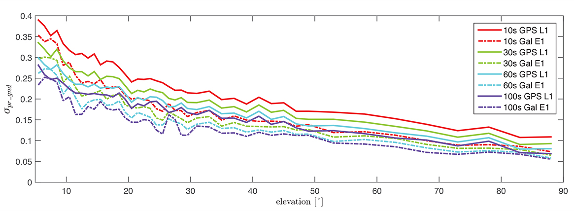
Figure 4 shows the evaluation of (σpr_gnd) for the Galileo E1, BOC(1,1) signal and the GPS L1 C/A signal for increasing smoothing time constants (10, 30, 60, and 100 seconds). Starting with a 10-second smoothing constant, Galileo E1 shows much better performance than GPS L1. The difference shrinks as the smoothing constant increases due to the effectiveness of smoothing in reducing noise and short-delay multipath. However, even with 100-second smoothing (the purple curves), Galileo E1 BOC(1,1) shows lower values of (σpr_gnd).
Figure 4. σ(pr_gnd) versus elevation for Galileo E1 (dotted lines) and GPS L1 (solid lines for different smoothing constants: red (10s), green (30s), cyan (60s), purple (100s).
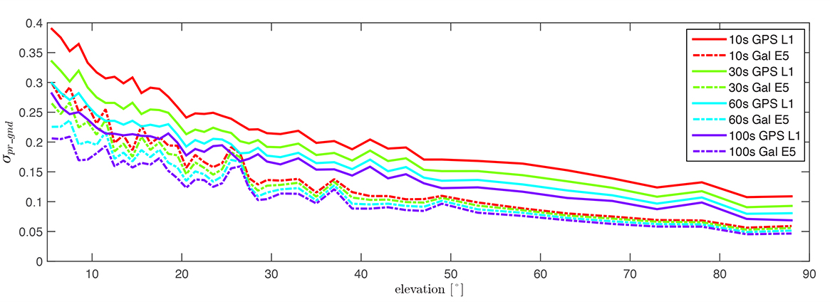
A similar comparison is presented in Figure 5, of the performance of GPS L1 and Galileo E5a. The Galileo E5a signal is significantly less affected by multipath, and the difference stays more pronounced than in the Galileo E1 – GPS L1, even with 100-second smoothing. It can be also observed that the Galileo signals have a lower sensitivity to the smoothing constant. The Galileo E1 signal shows an increase of sensitivity for low elevations (below 40°), while on E5a, a smoothing constant larger than 10 seconds has almost no impact on the residual error. Thus, a shorter smoothing constant on Galileo E5a generates approximately the same residual noise and multipath a 100-second smoothing constant on GPS L1.
Figure 5. σ(pr_gnd) versus elevation for Galileo E5a (dotted lines) and GPS L1 (solid lines) for different smoothing constants: red (10s), green (30s), cyan (60s), purple (100s).
The values for (σpr_gnd) are, however, impacted by the number of satellites which are used to determine a correction. Since only a very limited number of satellites broadcasting L5 and Galileo signals are currently available, these results should be considered preliminary. The first evaluations strongly indicate that with the new signals, we get better ranging performance. Based on the performance advantage of the new signals, a decrease of the smoothing constant is one option for future application. This would reduce the time required (for smoothing to converge) before including a new satellite or re-including a satellite after it was lost.
In the current GAST-D implementation, based on GPS L1 only, guidance is developed based on a 30-second smoothing time constant. A second solution, one with 100 seconds of smoothing, is used for deriving the Dv and Dl parameters from the DSIGMA monitor and thus for protection level bounding (it is also used for guidance in GAST-C). During the flight, different flight maneuvers or the blockage by the airframe can lead to the loss of the satellite signal.
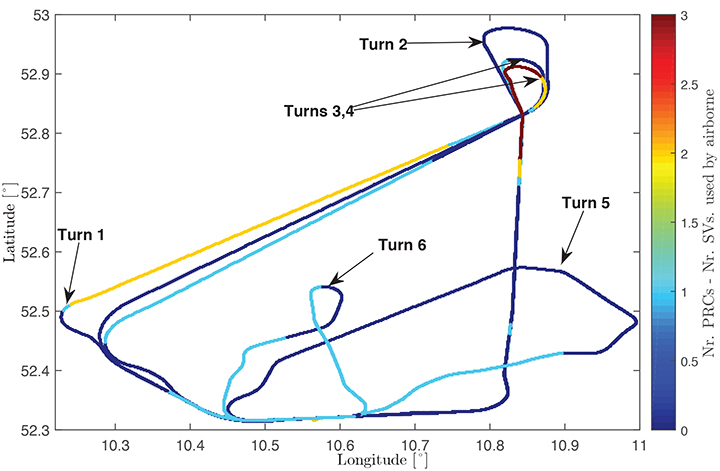
Figure 6 shows the ground track of a recent flight trial conducted by DLR in November 2014. The colors represent the difference between the number of satellites used by the ground subsystem (with available corrections) and the number of satellites used by the airborne subsystem in the GAST-D position solution. One of the purposes of the flight was to characterize the loss of satellite signals in turns. In turns with a steeper bank angle, up to 3 satellites are lost (Turns 1, 3, and 4), while on a wide turn with a small bank angle (Turn 2), no loss of satellite lock occurred. It is also possible for airframe to block satellite signals, leading to a different number of satellites between ground and airborne even without turns.
Figure 6. Ground track of a flight trial conducted by DLR. The colors represent difference between number of SVs used by the ground system and number of SVs used by the airborne.
With this in mind, a shorter smoothing constant would allow the satellites lost to turns or to airframe blockage to be re-included more rapidly in the position solution. However, a new smoothing constant would have to be validated with a larger amount of data. Data from flights trials has to be evaluated as well to confirm that similar levels of performance are reresentative of the air multipath and noise.
In a future dual-frequency GBAS implementation, an important advantage of lower multipath and noise is to improve the Ifree position solution. In earlier research, we demonstrated that the error level of the Dfree solution is almost the same as for single-frequency, but an increase in error by a factor of 2.33 was computed for the Ifree standard deviation based on L1 C/A code and L2 semi-codeless measurements.
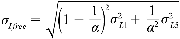
If the errors on L1 (E1) and L5 (E5a) code and carrier phase measurements are statistically independent the standard deviation of the σIfree can be written as,
(5)
where α=1−f 21 ∕ f 25, and σL1,σL5 represent the standard deviations of the smoothed noise and multipath for L1 (E1) and L5 (E5a), respectively. Considering σpr_gnd,L1(E1)) = σpr_gnd,L5(E5a)) in equation (5), the noise and multipath error on Ifree (σIfree) increases by a factor of 2.59.
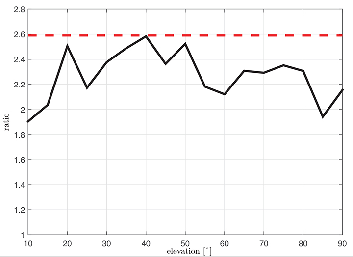
Figure 7 shows the ratio σIfree/σL1 using measured data. We observe that the measured ratio (the black curve) is below the theoretical ratio computed based on the assumption of statistically independent samples (the constant value of 2.59). This is explained by the fact that the multipath errors in the measurements are not independent but have some degree of statistical correlation. The standard deviations are computed based on the same data set used in the raw multipath and noise assessment using 100-second smoothed measurements sorted into elevation bins of 10° spacing.
Figure 7. Measured ratio σIfree/σL1 function of elevation.
Conclusion
We have shown how GBAS can benefit from the new signals provided by the latest generation of GPS and Galileo satellites. We have demonstrated improved performance in terms of lower noise and multipath in data collected in our GBAS test bed. When GBAS is extended to a multi-frequency and multi-constellation system, these improvements can be leveraged for improved availability and better robustness of GBAS against ionospheric and other disturbances.
Acknowledgment
Large portions of this work were conducted in the framework of the DLR internal project, GRETA.
Manufacturers
The ground facility consists of four JAVAD GNSS Delta receivers, all connected to Leica AR 25choke ring antennas.
Mihaela-Simona Circiu is is a research associate at the German Aerospace Center (DLR). Her research focuses on multi-frequency multi-constellation Ground Based Augmentation System. She obtained a 2nd level Specialized Master in Navigation and Related Applications from Politecnico di Torino.
MIchael Felux is is a research associate at the German Aerospace Center (DLR). He is coordinating research in the field of ground-based augmentation systems and pursuing a Ph.D. in Aerospace Engineering at the Technische Universität München.
Sam Pullen is a senior research engineer at Stanford University, where he is the director of the Local Area Augmentation System (LAAS) research effort. He has supported the FAA and others in developing GNSS system concepts, requirements, integrity algorithms, and performance models since obtaining his Ph.D. from Stanford in Aeronautics and Astronautics.