Tag: multi-GNSS receiver

  • Interchangeability Accomplished

    Tri-Band Multi-Constellation GNSS in Smartphones and Tablets

    This article presents a single-chip BeiDou/Galileo/GLONASS/
    GPS/QZSS/SBAS architecture for use in cell phones and tablets. The authors explain the advantages to end users of multiple constellations. They also examine the details of system interchangeability, multi-system issues, and how assisted-GNSS data operates with all constellations, including BeiDou.

    By Frank van Diggelen and Kathy Tan

    With GPS, GLONASS, SBAS, BeiDou, QZSS, and Galileo there are over eighty operational satellites. Why do we need all these satellites in the first place? The answer is simple: in urban environments we want a few (six to eight) good satellites with an unobstructed line-of-sight (LoS) to the receiver and good horizontal dilution of precision (HDOP). In order to achieve this, we need many more satellites in space than any single constellation. In this article, we address the following issues.

    • Receiver intersystem RF bias with a tri-band front-end. BeiDou uses a different RF section than GPS/Galileo/QZSS/SBAS and GLONASS. As a result, there is a receiver intersystem bias between BeiDou and each of these other systems—not just because BeiDou is on a different frequency, but because of the different RF path through the receiver. We explain how this bias is calibrated and removed.
    • In the space segment there are intersystem biases primarily caused by differences in time standards. We discuss time management and show how the different systems can be made interoperable.
    • BeiDou Assistance. In order to realize the benefits mentioned, we need infrastructure deployment for BeiDou assistance in accordance with 3GPP standards. We will discuss what is available, and what is left to do.
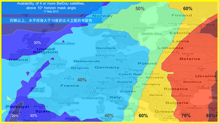
    • Coverage outside of China. Europeans can see more BeiDou satellites than Galileos. At the time of writing (March 2014) they could see approximately twice as many. Thus, when used in a multi-GNSS receiver, BeiDou is far from being just a regional system. We will provide coverage analysis, and live-test data, including a focus on Europe.
    • Finally, we will demonstrate all of the above in practice, explaining and showing how interchangeability is achieved, and where first fixes can be computed with no more than one of each satellite type.

    Figure 1 illustrates the point referenced at the beginning, that we need many more satellites in space than any single constellation.

    All of the lines in Figure 1 show signals that were actively tracked by the receiver at the position shown on the right. The orange lines are to satellites that are blocked, but the reflected signal is tracked. We do not want to use these measurements if we can help it, so we need many satellites to provide enough LoS signals.

    Let’s look at the HDOP of the LoS signals. In this example, the HDOP for the three LoS GPS satellites was 50. For the three LoS GLONASS satellites, the HDOP was 45. However, with the combined GNSS constellation, the HDOP for the six LoS satellites was 2.2. In other words, we expect about a 20x accuracy improvement by using the combined constellation.

    There are many places and times in cities where we see just one or two direct LoS signals from a particular constellation, and we need more than just GPS and GLONASS to get the desired number of good signals, thus explaining the desire and need for all available constellations.

    We’ll now look at the coverage provided by BeiDou2, which has five Geostationary satellites (GEOs), five inclined Geosynchronous satellites (GSOs), and four Medium Earth Orbit satellites (MEOs). With this 14-satellite constellation, the global coverage is as shown in Figure 2. This figure shows the percentage of time in a day that four or more BeiDou satellites are visible above a 10-degree mask angle. In the Asia-Pacific region, where the GEOs and GSOs are positioned, the coverage is predictably 100 percent. In fact, there are seven or eight BeiDou satellites visible in much of this region most of the time.

    Figure 2. BeiDou2 global coverage.
    Figure 2. BeiDou2 global coverage.

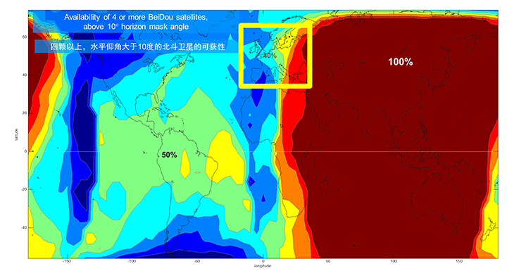
    As shown in Figure 3, outside the Asia-Pacific region the coverage is also interesting. We see that at least four BeiDou satellites are available over Europe about half of the time. This is quite significant given the previous discussion; even one or two extra satellites can make all the difference in an urban environment. Another notable fact is that, for now at least, Europe can see more BeiDou than Galileo satellites.

    Figure 3. BeiDou coverage over Europe. The different colors show the percent of time that four or more BeiDou satellites are visible above a 10° mask angle.
    Figure 3. BeiDou coverage over Europe. The different colors show the percent of time that four or more BeiDou satellites are visible above a 10° mask angle.

    Technical Requirements

    There are five significant technical requirements that we want to satisfy when creating a multi-GNSS receiver for consumer applications:

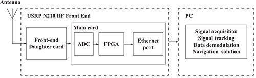
    Three Separate RF Paths. To acquire and track all of the satellites already mentioned, we need three separate RF paths. Details follow in Section 3 (Front-End Architecture).

    Search and Track capability for all visible GNSS satellites. The receiver must have the ability to search a very large number of code-frequency bins at once.

    Host-Based. As much as possible, we want to make use of the host application processor (AP) and memory. This allows for tight integration with assistance data (which is coming from the host), other sensors, and other wireless data (such as Wi-Fi and Bluetooth for indoor locations). A host-based architecture also keeps size and cost as low as possible.

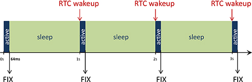
    With Host-Offload. A significant trend in location applications is the need for “always-on low power” location. The host AP cannot be used for continuous position updates, since it draws too much power. So, while we want host-based location when the host AP is active (such as when navigating with turn-by-turn directions and a map), we also want a host-offload capability so that the GNSS chip can compute positions internally while the host is asleep.

    Interchangeability. The ultimate requirement for multi-system GNSS is the ability to use any combinations of satellites as if they were all in the same constellation. This is summarized as “any four satellites will do.”

    Front-End Architecture

    From a cell phone/tablet perspective, the signals in space are all in the L1 band, with frequencies as shown in Figure 4. The key architecture feature of the GNSS front-end is that it should have three separate RF chains for the three separate frequencies-of-interest; see Figure 5.

    Figure 4. Frequencies-of-interest for GNSS in cell phones.
    Figure 4. Frequencies-of-interest for GNSS in cell phones.
    Figure 5. Front-end architecture showing three RF chains.
    Figure 5. Front-end architecture showing three RF chains.

    Baseband Architecture

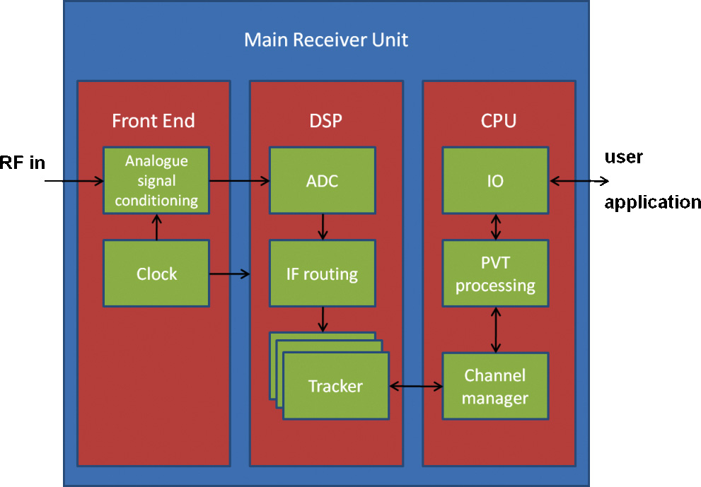
    The preferred architecture of a chip, as shown in Figure 6, is host-based to take advantage of the large host CPU when it is active. When the host CPU is asleep, a small, low-power, on-chip CPU is leveraged for background “always on” location. This enables applications such as geofencing to run without significantly reducing battery life.

    Figure 6. Block diagram of the preferred architecture, showing a host-based configuration that includes a host-offload capability for geofencing and position caching on-chip when the host is asleep.
    Figure 6. Block diagram of the preferred architecture, showing a host-based configuration that includes a host-offload capability for geofencing and position caching on-chip when the host is asleep.

    When the host is active, such as when you are actively using the phone for turn-by-turn navigation, the host AP is on and we want to make as much use as possible of the host AP and memory. This allows for tight integration with assistance data coming from the host, other sensors, and other wireless data (such as Wi-Fi and Bluetooth for indoor locations). A host-based architecture also keeps size and cost as low as possible, even with host-offload capability, which adds very little to the size of the chip.

    Receiver Intersystem RF Biases

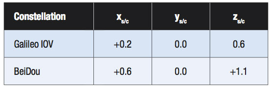
    With the three different bands of frequencies, we will get RF group delays in the receiver front-end. These must be calibrated out by the receiver’s designer as part of the chip’s system design. If the group delay between BeiDou and GPS is not calibrated, it will lead to approximately three meters of bias between the two systems (Figure 7). Once it is calibrated, there is essentially no bias.

    Figure 7. L1 frequency spectrum for BeiDou2, GPS, Galileo, QZSS, SBAS, and GLONASS.
    Figure 7. L1 frequency spectrum for BeiDou2, GPS, Galileo, QZSS, SBAS, and GLONASS.

    Satellite Intersystem Biases

    Different GNSS constellations run off their own master clocks; referenced to different realizations of UTC. GPS is referenced to UTC (USNO), QZSS is referenced to UTC (NICT), GLONASS to UTC (SU), BeiDou to UTC (NTSC), and Galileo to UTC (INRIM). GLONASS UTC (SU) differs from the others by 3 hours.

    Furthermore, different systems treat leap seconds differently. This is indicated by the red arrows in the clocks in FIGURE 8. GPS, QZSS, BeiDou and Galileo system times are continuous and ignore leap seconds. Thus, each system time is ahead of UTC by a number of leap seconds. GPS time started in 1980 in synch with UTC; there have been 16 leap seconds since, so now GPS is 16 seconds ahead of UTC. QZSS and Galileo system times were started in synch with GPS. BeiDou system time was started in 2006 in synch with UTC; there have been 2 leap seconds since, so now BeiDou is 2 seconds ahead of UTC. GLONASS system time, on the other hand, includes leap seconds.

    Apart from this, each of the different realizations of UTC is within several nanoseconds of the others.

    To combine measurements from these different systems and avoid any time-induced intersystem biases, we need to resolve the time offsets. Each system transmits the delta-time between its system time and the systems that preceded it, as listed in Figure 8. To combine the systems, we either need to decode these data messages or obtain the delta-time values from Assisted GNSS.

     Figure 8. Intersystem time differences and broadcast delta-time values from each system.
    Figure 8. Intersystem time differences and broadcast delta-time values from each system.

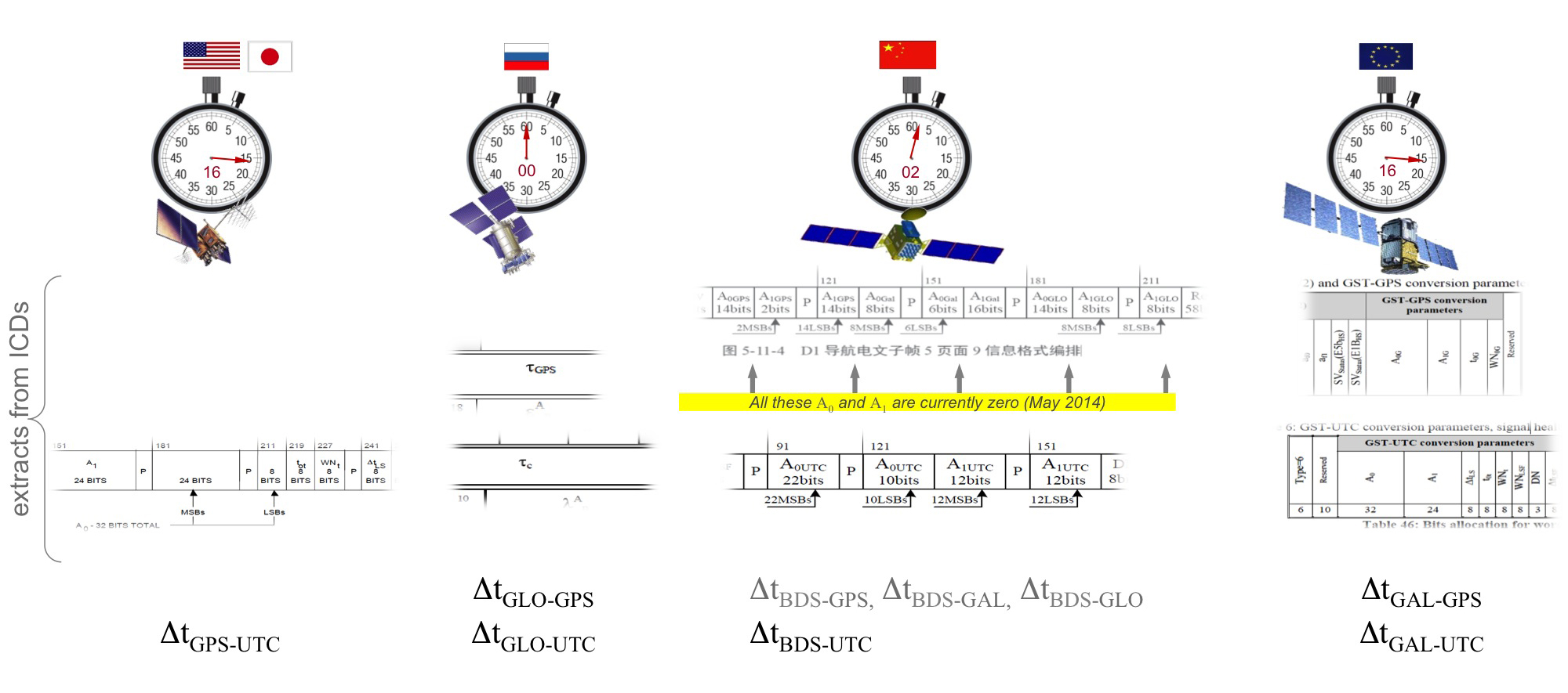
    Note, however, that in the BeiDou broadcast Nav message the intersystem time-offset data values are all set to zero (even though the true offsets are not zero).

    Assisted-GNSS Including BeiDou

    Assisted GNSS, or A-GNSS, increases sensitivity and decreases the time-to-first-fix of a receiver by providing assistance data in the form of the receiver’s approximate position, time and frequency, as well as all data that the receiver might decode from the broadcast signals. The assistance data may also include data beyond what is broadcast, in particular, let’s focus on BeiDou time offsets. The BeiDou time offset to the other systems is included in the BeiDou broadcast Nav message as shown in Figure 8; however, at present these data values are all set to zero (even though the true offsets are not zero). Thus, in order to get these offsets and integrate BeiDou properly into a combined GNSS system, one must compute the offsets at a reference station and provide them as part of the assistance data, as shown in Figure 9.

    Figure 9. A-GNSS provides broadcast satellite data over some other wireless network, as well as time-offsets between the different pairs of systems.
    Figure 9. A-GNSS provides broadcast satellite data over some other wireless network, as well as time-offsets between the different pairs of systems.

    Commercial Implementation

    The preferred architecture described in this article has been implemented in a commercial GNSS receiver that is now available for commercial host-based products, such as cell phones and tablets. The chip, Broadcom’s BCM47531, is the first consumer GNSS chip with a tri-band front-end capable of acquiring and tracking satellites from GPS, SBAS, QZSS, GLONASS, and BeiDou constellations, simultaneously; and operating in host-based mode for navigation and in host-offload mode for Always-On location.

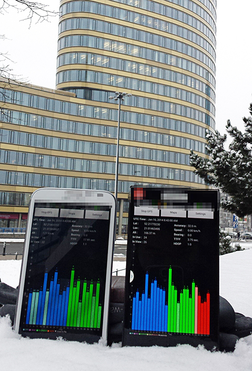
    Broadcom has collaborated with leading smartphone manufacturers to launch the first wave of BeiDou enhanced consumer smartphones. Figure 10 shows one of these smartphones being tested in Europe. Note the number of BeiDou satellites in view. As predicted by the availability plots shown earlier, there are many BeiDou satellites in view (in this case, six).

    Figure 10. GPS/GLONASS phone and GPS/GLONASS/BeiDou phone being tested in Warsaw, Poland. Note the six BeiDou satellites (red) that are seen and tracked by the BeiDou phone.
    Figure 10. GPS/GLONASS phone and GPS/GLONASS/BeiDou phone being tested in Warsaw, Poland. Note the six BeiDou satellites (red) that are seen and tracked by the BeiDou phone.

    Interchangeability: Any Four

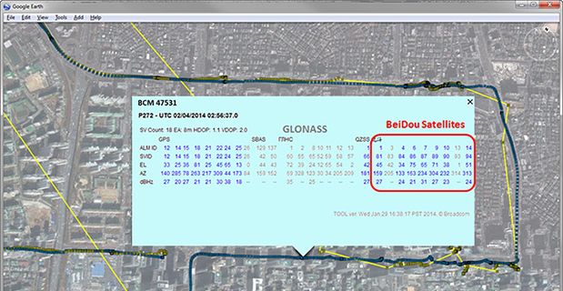
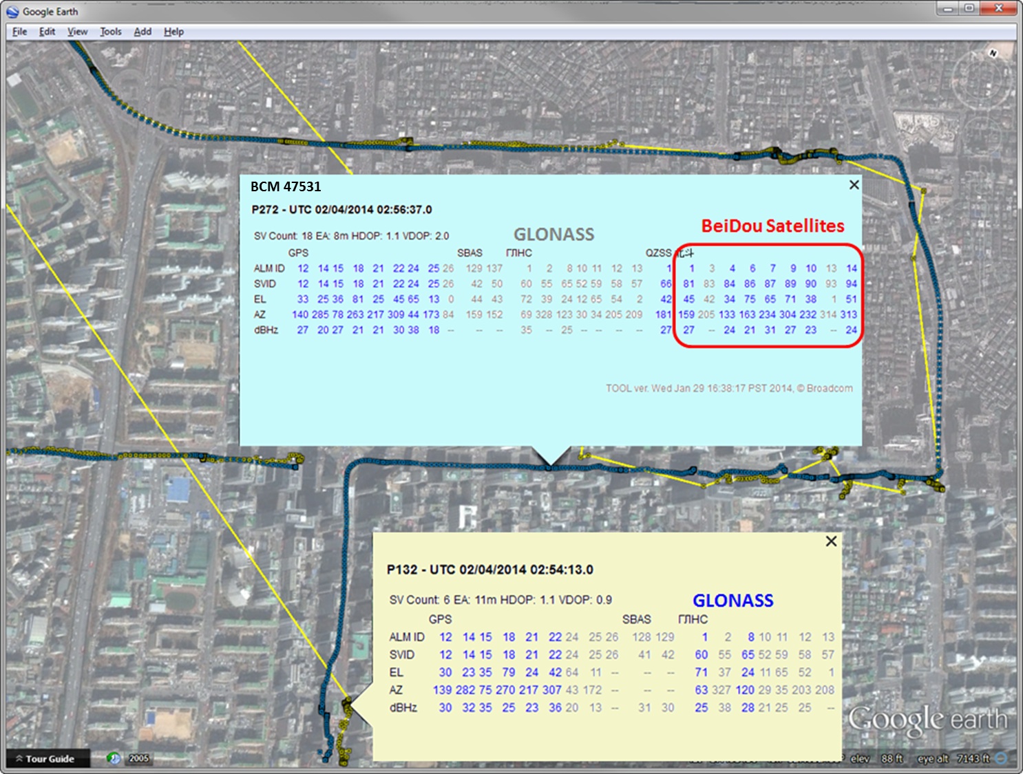
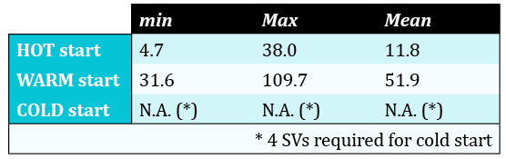
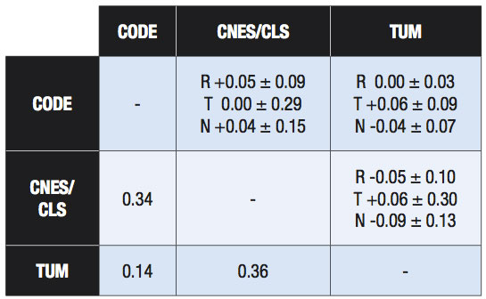
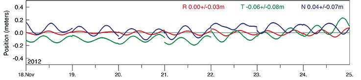
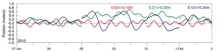
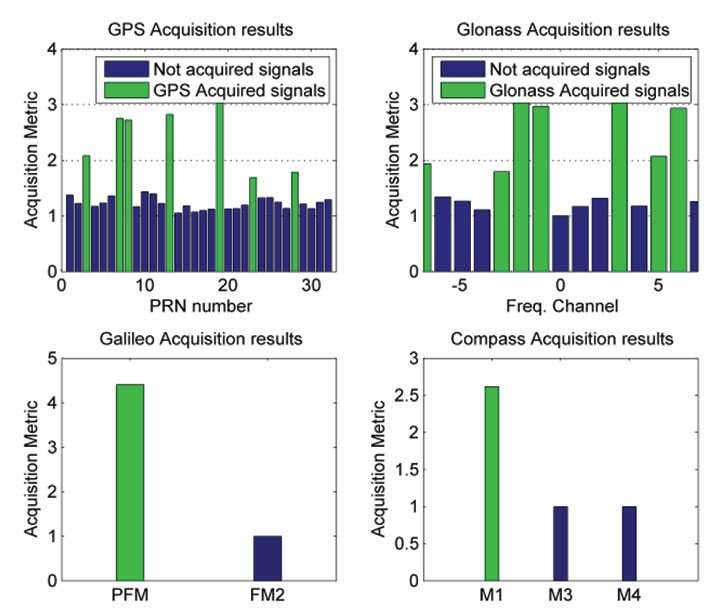
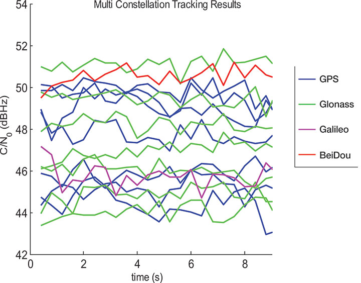
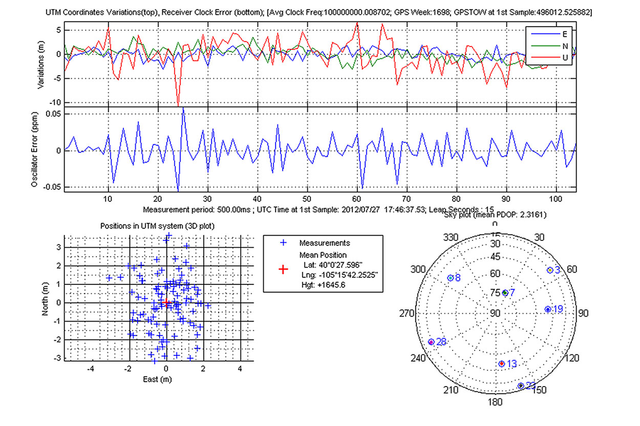
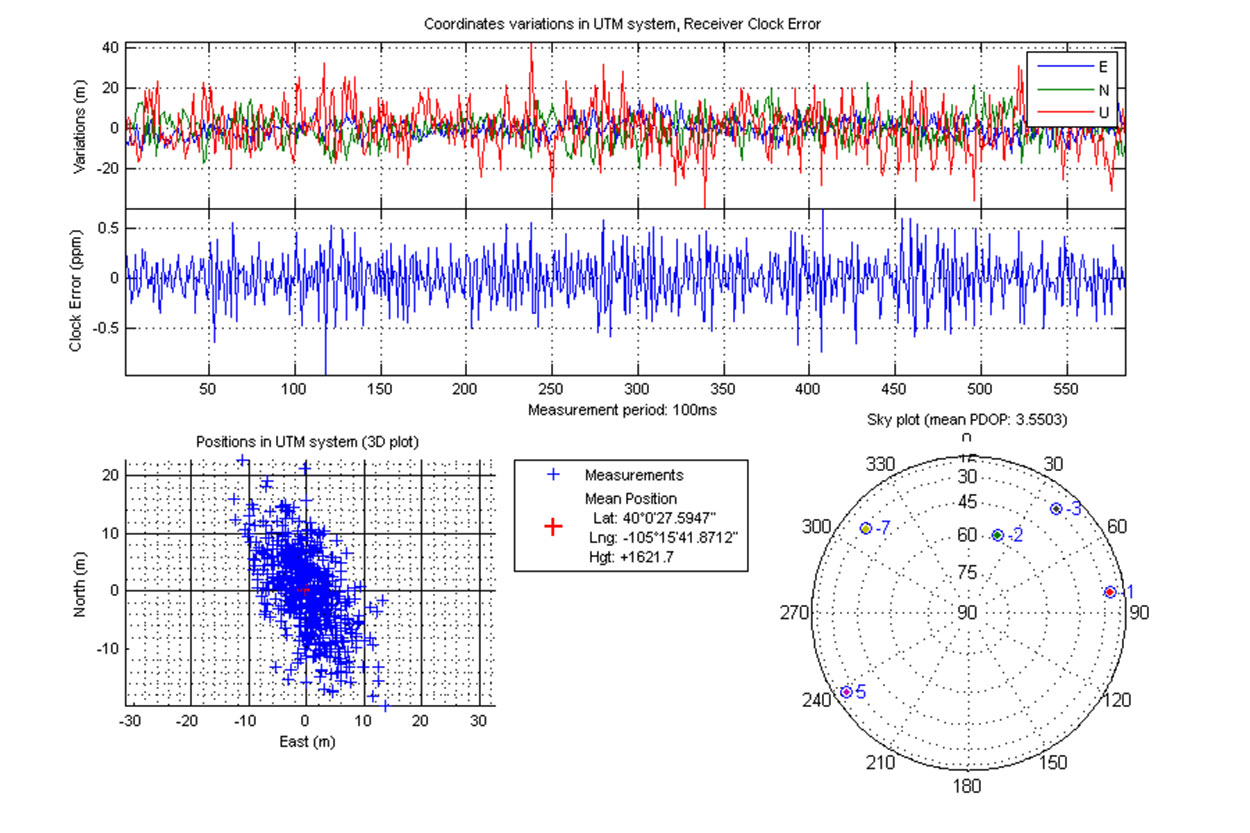
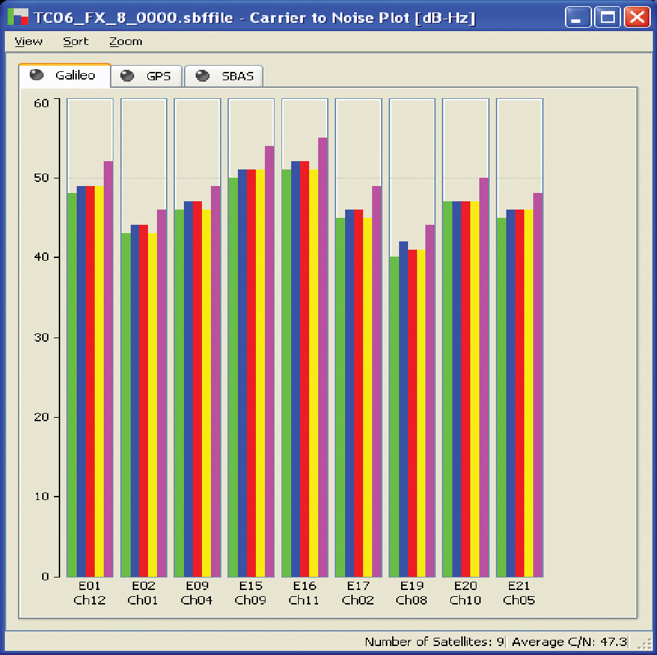
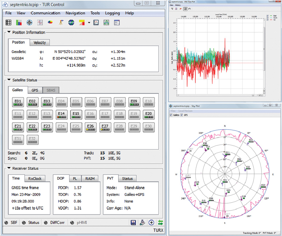
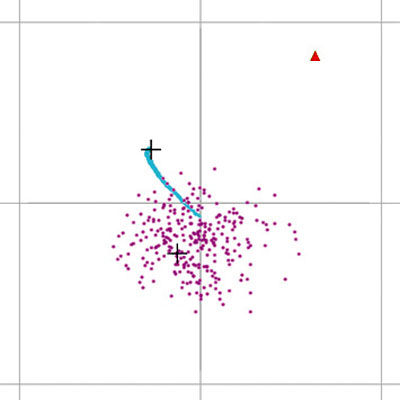
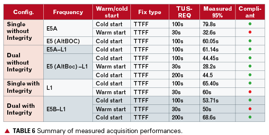
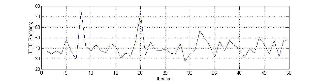
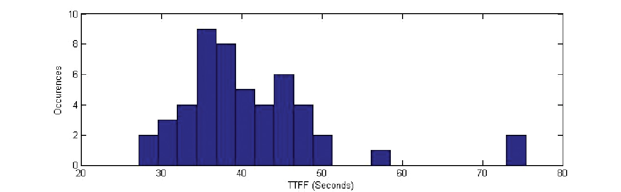
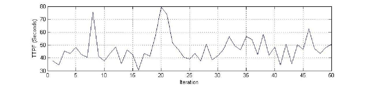
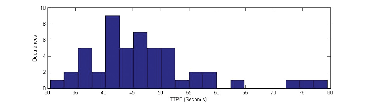
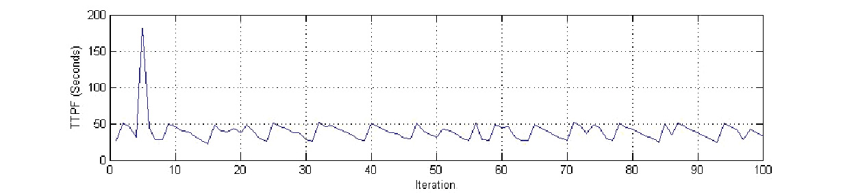
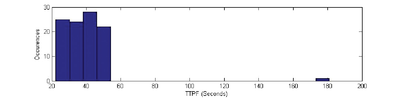
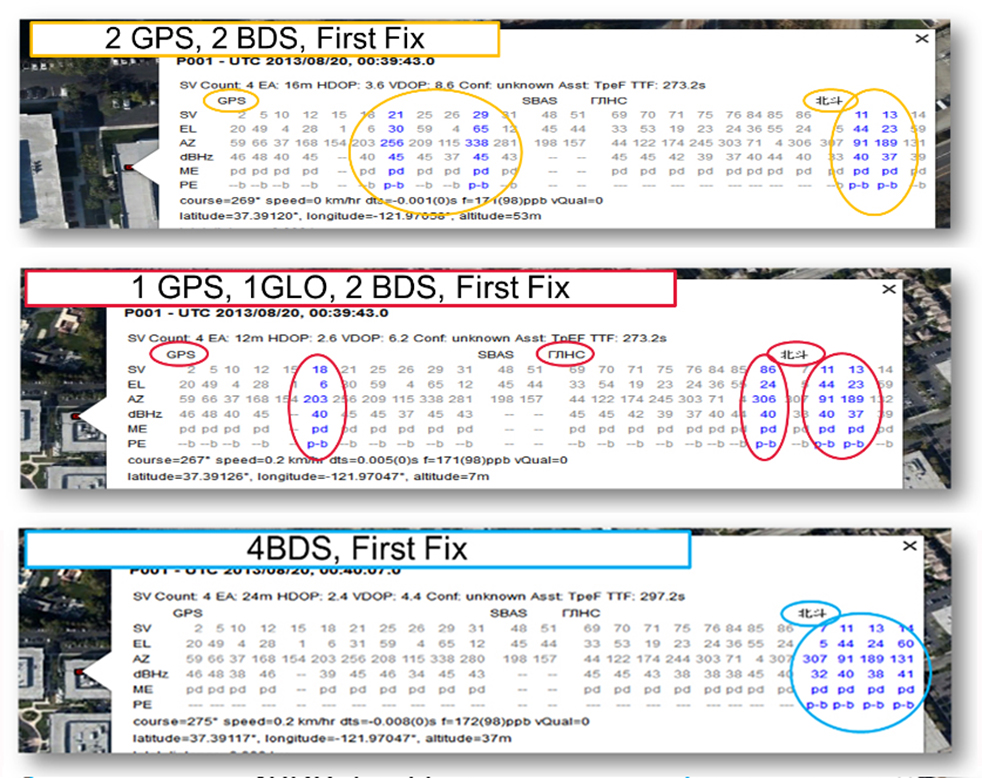
    Now that we have addressed all of the major issues related to integrating different GNSS systems (in particular BeiDou), we can demonstrate the payoff.This is the achievement of interchangeability, where any GNSS satellites can be used together, as if they all belong to a single constellation. Figures 11 and 12 show assisted cold starts, where first fixes are obtained with no prior knowledge other than that provided by A-GNSS data. In each case, we show a different combination of satellites; including one satellite from each of four different constellations, and all four from BeiDou.

    Figure 11. Interchangeability: Position fix with 1 GPS satellite, 1 GLONASS, 1 QZSS, and 1 BeiDou. The receiver is in Perth, Australia, where all of these constellations can be seen.
    Figure 11. Interchangeability: Position fix with 1 GPS satellite, 1 GLONASS, 1 QZSS, and 1 BeiDou. The receiver is in Perth, Australia, where all of these constellations can be seen.
    Figure 12. Interchangeability: Assisted cold start, first fixes. Blue numbers show the satellites used in the position fix (top: two GPS and two BeiDou; middle: one GPS, one GLONASS, and two BeiDou; and bottom: four BeiDou only). The receiver is in San Jose, California, where four BeiDou satellites can be seen some of the time (some of the BeiDou GSOs can be seen and all the BeiDou MEOs can be seen for a few hours each day).
    Figure 12. Interchangeability: Assisted cold start, first fixes. Blue numbers show the satellites used in the position fix (top: two GPS and two BeiDou; middle: one GPS, one GLONASS, and two BeiDou; and bottom: four BeiDou only). The receiver is in San Jose, California, where four BeiDou satellites can be seen some of the time (some of the BeiDou GSOs can be seen and all the BeiDou MEOs can be seen for a few hours each day).

    Multi-Constellation Robustness

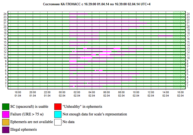
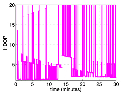
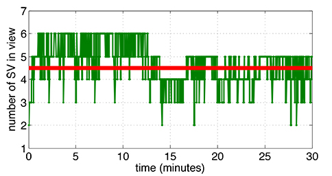
    While this article was being edited, the GLONASS system provided us with the most dramatic demonstration yet of the need for, and benefits of, multi-constellation receivers. On April 2, 2014, the GLONASS system failed spectacularly for a period of 11 hours. Receivers that used GPS and GLONASS had very large position errors, or no positions at all. While the receiver discussed in this article, the BCM47531, operated seamlessly. This receiver tracked GPS, GLONASS, QZSS and BeiDou satellites, correctly identified the faulty GLONASS satellites, and automatically stopped using them.

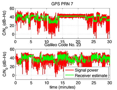
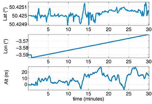
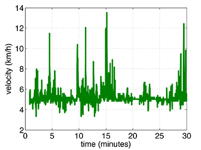
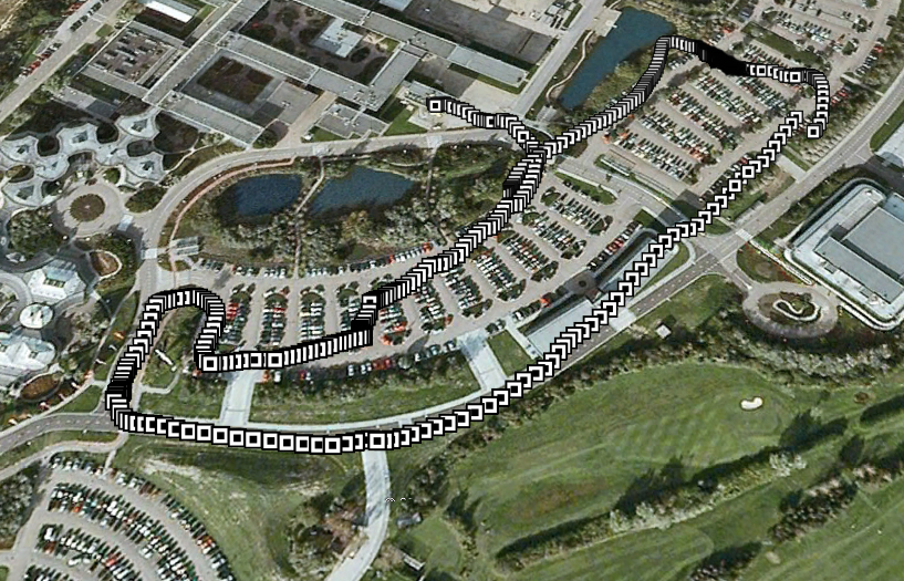
    The details of the incident are as follows: The GLONASS control system uploaded incorrect orbit data to several satellites. When receivers used these satellites they had position errors of hundreds of meters, or no positions at all. At that time, the BCM47531 was being tested alongside a GPS/GLONASS receiver, and we have the data to show what happened. The receiver using only GPS/GLONASS suffered position errors of ten thousand meters, and long periods with no position at all; at the same time the multi-constellation receiver produced continual positions with normal accuracy. Figure 13 shows the test data ­­— the left most image shows the route being driven, the middle image shows the data from the GPS/GLONASS receiver, and the right image shows the data from the BCM47531 multi-GNSS receiver. Figure 14 shows the details of the multi-GNSS receiver, you can see that no GLONASS satellites are being used.

    FIGURE 13. Side-by-side tests of GPS/GLONASS receiver and multi-constellation receiver during the GLONASS incident of April 2, 2014. The GPS/GLONASS receiver produced errors of ten thousand meters and long periods with no position at all, while the multi-constellation BCM47531 operated seamlessly.
    FIGURE 13. Side-by-side tests of GPS/GLONASS receiver and multi-constellation receiver during the GLONASS incident of April 2, 2014. The GPS/GLONASS receiver produced errors of ten thousand meters and long periods with no position at all, while the multi-constellation BCM47531 operated seamlessly.
    FIGURE 14. Detail from the multi-constellation receiver when there is a problem with some satellites. The errors are recognized automatically by algorithms comparing the measurements to redundant measurements from the extra constellations, and the erroneous signals are not used.
    FIGURE 14. Detail from the multi-constellation receiver when there is a problem with some satellites. The errors are recognized automatically by algorithms comparing the measurements to redundant measurements from the extra constellations, and the erroneous signals are not used.

    This incident may raise the question: Why use GLONASS at all, why not just GPS? The answer is that in urban canyons, such as where this test was done, GPS alone does not have enough satellites to give the performance now expected in consumer products — for the reasons explained in the beginning of this article. Also, GPS, although it has been more reliable than GLONASS, is not immune to failures or jamming itself. The lesson of this incident is that reliability and accuracy comes from the combination of all the available constellations, with a receiver that can use the signals interchangeably.

    Conclusion

    We have shown the preferred architecture for a consumer GNSS receiver that includes all of the available constellations. We have addressed the major requirements of such a receiver for the consumer market, in particular, for cell phones and tablets. A receiver that meets these requirements is now available, the Broadcom BCM47531, has been designed into a new generation cell phones and tablets for 2014. Finally, we have shown how, with this receiver, the ultimate GNSS goal of interchangeability can be achieved.


    Frank van Diggelen is vice president of technology at Broadcom Corporation, a consulting professor at Stanford University, and inventor of coarse-time GNSS navigation, co-inventor of Long Term Orbits for A-GNSS, and author of A-GPS: Assisted GPS, GNSS, and SBAS.

    Kathy Tan is a senior principal engineer at Broadcom Corporation. She has worked on GNSS development and Assisted GNSS for Ashtech, Magellan, Global Locate and Broadcom. She received her MS and BS in electrical engineering from Fudan University, China.

  • How to Survive a Total Constellation Outage

    How to Survive a Total Constellation Outage

    Yesterday we posted news of an 11-hour downtime for the full GLONASS constellation, due to an upload of bad ephemerides. Coincidentally, during that 11-hour period, the mass-market chip company Broadcom was conducting multi-constellation receiver tests in Asia. Frank van Diggelen, Broadcom’s chief GNSS scientist and vice president says, “We have definitive data to show how a multi-constellation receiver survives such an outage.”

    Here are the pictures, and the story they tell.

    Test data coincident with the GLONASS ephemeris disruption of April 1 and 2 showing conclusively how a GPS/GLONASS/QZSS/BEIDOU receiver survives the complete disruption of one of the constellations.

    On April 2 at 1:00 a.m. Moscow time, bad ephemeris was uploaded to all satellites (see chart at the bottom of this story).

    There are two receivers shown here, from two different manufacturers, both in smartphones. The yellow dots are for a GPS/GLONASS receiver; the blue dots are from the Broadcom 47531 receiver which tracks GPS/GLONASS/QZSS/BeiDou signals simultaneously. The 47531 receiver includes logic to use redundant measurements to check the validity of all measurements. It successfully identified and removed the bad GLONASS ephemeris 100 percent of the time, as can be seen by the continuity and accuracy of the positions.

    Broadcom2

    Here is the satellite outage chart from yesterday’s story.  All GLONASS satellites were restored to healthy state after the 11-hour interruption.

    Current plot from the Roscosmos GLONASS Information-Analytical Centre. Things are almost back to normal this morning.
    Current plot from the Roscosmos GLONASS Information-Analytical Centre. Things are almost back to normal this morning.


  • A Mass-Market Galileo Receiver

    Its Algorithms and Performance

    The authors test three mass-market design drivers on a chip developed expressly for a new role as a combined GPS and Galileo consumer receiver: the time-to-first-fix for different C/N0, for hot, warm, and cold start, and for different constellation combinations; sensitivity in harsh environments, exploiting a simulated land mobile satellite multipath channel and different user dynamics; and power consumption strategies, particularly duty-cycle tracking.

    By Nicola Linty, Paolo Crosta, Philip G. Mattos, and Fabio Pisoni

    The two main GNSS receiver market segments, professional high-precision receivers and mass-market/consumer receivers, have very different structure, objectives, features, architecture, and cost. Mass-market receivers are produced in very high volume — hundreds of millions for smartphones and tablets — and sold at a limited price, and in-car GNSS systems represent a market of tens of millions of units per year. The reason for these exploding markets can be found not only in the improvements in electronics and integration, but also in the increasing availability of new GNSS signals. In coming years, with Galileo, QZSS, BeiDou, GPS-L1C, and GLONASS-CDMA all on the way, the silicon manufacturer must continue the path towards the fully flexible multi-constellation mass-market receiver.

    Mass-market receivers feature particular signal processing techniques, different from the acquisition and tracking techniques of standard GNSS receivers, in order to comply with mobile and consumer devices’ resources and requirements. However, a limited documentation is present in the open literature concerning consumer devices’ algorithms and techniques; besides a few papers, all the know-how is protected by patents, held by the main manufacturers, and mainly focused on the GPS L1 C/A signal. We investigate and prove the feasibility of such techniques by semi-analytical and Monte Carlo simulations, outlining the estimators sensitivity and accuracy, and by tests on real Galileo IOV signals.

    To understand, analyze, and test this class of algorithms, we implemented a fully software GNSS receiver, running on a personal computer. It can process hardware- and software-simulated GPS L1 C/A and Galileo E1BC signals, as well as real signals, down-converted at intermediate frequency (IF), digitalized and stored in memory by a front-end/bit grabber; it can also output standard receiver parameters: code delay, Doppler frequency, carrier-to-noise power density ratio (C/N0), phase, and navigation message. The software receiver is fully configurable, extremely flexible, and represents an important tool to assess performance and accuracy of selected techniques in different circumstances.

    Code-Delay Estimation

    The code-delay estimation is performed in the software receiver by a parallel correlation unit, giving as output a multi-correlation with a certain chip spacing. This approach presents some advantages, mostly the fact that the number of correlation values that can be provided is thousands of times greater, compared to a standard receiver channel. Use of multiple correlators increases multipath-rejection capabilities, essential features in mass-market receivers, especially for positioning in urban scenarios. The multi-correlation output is exploited to compute the received signal code delay with an open-loop strategy and then to compute the pseudorange.

    In the simulations performed, the multi-correlation has a resolution of 1/10 of a chip, which is equivalent to 30 meters for the signals in question; to increase the estimate accuracy, Whittaker-Shannon interpolation is performed on the equally spaced points of the correlation function belonging to the correlation peak.

    The code-delay estimate accuracy is reported in Figures 1 and 2. The results are obtained with Monte Carlo simulations on simulated GNSS signals, with sampling frequency equal to 16.3676 MHz. In particular, a GPS L1 C/A signal is considered, affected by constant Doppler frequency equal to zero for the observation period, to avoid the effect of dynamics. The figures show the standard deviation of the code estimation error, that is, the difference between the estimated code delay and the true one, expressed in meters (pseudorange error standard deviation) for different values of C/N0. To evaluate the quality of the results, the theoretical delay locked loop (DLL) tracking jitter is plotted for comparison, as

    Linty-E1

    where Bn is the code loop noise bandwidth, Rc is the chipping rate, Bfe is the single sided front-end bandwidth, Tc is the coherent integration time, and c is the speed of light.

    In the two figures, the red curve shows the theoretical tracking jitter for a DLL, which can be considered as term of comparison for code-delay estimation. To correlate the results, a E-L spacing equal to D = 0.2 chip is chosen, and the code-delay error values of the software receiver simulation are filtered with a moving average filter. By averaging 0.5 seconds of data (for example, L = 31 values spaced 16 milliseconds), an equivalent closed-loop bandwidth of about 1 Hz can be obtained:

    Linty-E2

    In particular, in Figure 1, a coherent integration time equal to 1 millisecond (ms) and 16 non-coherent sums are considered, while in Figure 2 a coherent integration time equal to 4 ms and 16 non-coherent sums, spanning a total time T=64 ms, are considered. In both cases, the software receiver results are extremely good for high C/N0. The code-delay error estimate is slightly higher than its equivalent in the DLL formulation. The open-loop estimation error notably increases in the first case below 40 dB-Hz due to strong outliers, whose probability of occurrence depends on the C/N0. In fact, this effect is smoothed in the second case, where the coherent integration time is four times larger, thus improving the signal-to-noise ratio.

    figure 1 Comparison between code delays estimation accuracy, Tc=1 ms , T=16 ms, B=1 Hz, D=0.2 chip.
    Figure 1. Comparison between code delays estimation accuracy, Tc=1 ms , T=16 ms, B=1 Hz, D=0.2 chip.
    figure 2 Comparison between code delays estimation accuracy, Tc=4 ms, T=64 ms, B=1 Hz, D=0.2 chip.
    Figure 2. Comparison between code delays estimation accuracy, Tc=4 ms, T=64 ms, B=1 Hz, D=0.2 chip.

    Nevertheless, the comparison between open loop multi-correlation approach and closed loop DLL is difficult and approximate, because the parameters involved are different and the results are only qualitative.

    Doppler Frequency Estimation

    In the particular case of the software receiver developed here, the residual Doppler frequency affecting the GNSS signal is estimated by means of a maximum likelihood estimator (MLE) on a snapshot of samples, exploiting open-loop strategy. In fact, despite the higher standard deviation of the frequency error (jitter), open-loop processing offers improved tracking sensitivity, higher tracking robustness against fading and interference, and better stability when increasing the coherent integration time. In addition, the open-loop approach does not require the design of loop filters, avoiding problems with loop stability. A certain number of successive correlator values, computed in the multiple correlations block, are combined in a fast Fourier transform (FFT) and interpolated.

    Figure 3 shows the root mean square error (RMSE) of the frequency estimate versus signal
    C/N0, obtained collecting 16 coherent accumulations of 4 ms of a Galileo E1B signal, then computing a 16 points FFT spanning a time interval of 64 ms, and finally refining the result with an interpolation technique. Three different curves are shown, corresponding respectively to:

    • the RMSE derived from simulations, carried out with GNSS data simulated with the N-FUELS signal generator;
    • a semi-analytical estimation, exploiting the same algorithm;
    • the Cramer-Rao lower bound (CRLB) for frequency estimation, shown as

    Linty-E3

    where fs is the sampling frequency.

    Figure 3. Doppler frequency estimate RMSE versus C/N0 in super-high resolution with T=64 ms, comparison between theoretical and simulated results.
    Figure 3. Doppler frequency estimate RMSE versus C/N0 in super-high resolution with T=64 ms, comparison between theoretical and simulated results.

    A well-known drawback is the so-called threshold effect. Below a certain C/N0, the frequency estimate computed with MLE suffers from an error, and the RMSE increases with respect to the CRLB.

    Mass-Market Design Drivers

    Once we have analyzed the features of some mass-market algorithms with a software receiver, we can move toward the performance of a real mass-market device, to compare results and confirm improvements brought by the new Galileo signals, so far mainly known from a theoretical point of view.

    A recent survey identified three main drivers in the design of a mass-market receiver, coming directly from user needs, and solvable in different ways.

    Time-to-first-fix (TTFF) corresponds to how fast a position, velocity, and time (PVT) solution is available after the receiver is powered on, that is, the time that a receiver takes to acquire and track a minimum of four satellites, and to obtain the necessary information from the demodulated navigation data bits or from other sources.

    Capability in hostile environments, for example while crossing an urban canyon or when hiking in a forest, is measured in terms of sensitivity. It can be verified by decreasing the received signal strength and/or adding multipath models.

    Power consumption of the device. GNSS chipset is in general very demanding and can produce a not-negligible battery drain.

    We analyzed these three drivers with a commercial mass-market receiver and with the software receiver.

    Open-Sky TTFF Analysis

    TTFF depends on the architecture of the receiver, for example the number of correlators or the acquisition strategy, on the availability of assistance data, such as rough receiver position and time or space vehicles’ (SV) ephemeris data, and on the broadcast navigation message structure. Some receivers, like the one used here for testing, embed an acquisition engine that can be activated on request and assures a low acquisition time; moreover, they implement ephemeris extension. In contrast, other consumer receiver manufacturers exploit a baseband-configurable processing unit, similar to the one implemented in the software receiver, with thousands of parallel correlators generating a multi-correlator output with configurable spacing, depending on the accuracy required. By selecting an appropriate number of correlators, depending on the available assistance data and on the accuracy required, the TTFF consequently varies.

    We assessed the performance of the receiver under test for different C/N0, for hot, warm, and cold start, and for different constellation combinations, exploiting hardware-simulated GNSS data. Good results are achieved, especially when introducing Galileo signals.

    Figure 4 reports the hot-start TTFF for different C/N0 values in the range 25–53 dB-Hz, computed using the receiver. The receiver, connected to a signal generator, is configured in dual-constellation mode (GPS and Galileo) and carries out 40 TTFF trials, with a random delay between 15 and 45 seconds. In a standard additive white Gaussian noise (AWGN) channel and in hot-start conditions, the results mainly depend on the acquisition strategy and on the receiver availability of correlators and acquisition engines. In an ideal case with open-sky conditions and variable C/N0, the introduction of a second constellation only slightly improves the TTFF performance; this result cannot be generalized since it mainly depends on the acquisition threshold of the receiver, which can change using signals of different constellations. In real-world conditions, the situation can vary.

    figure 4 Hot start TTFF for Galileo+GPS configuration versus C/N0 using the test receiver.
    Figure 4. Hot start TTFF for Galileo+GPS configuration versus C/N0 using the test receiver.

    Cold Start. Secondly, we analyze TTFF differences due to the different structure of GPS and Galileo navigation messages. The I/NAV message of the Galileo E1 signal and the data broadcast by GPS L1 C/A signals contain data related to satellite clock, ephemeris, and GNSS time: parameters relevant to the position fix since they describe the position of the satellite in its orbit, its clock error, and the transmission time of the received message.

    Table 1 shows some results in the particular case of cold start, with an ideal open-sky AWGN scenario. The TTFF is significantly lower when using Galileo satellites: while the mean TTFF when tracking only GPS satellites is equal to about 31.9 seconds (s), it decreases to 24.7 s when considering only Galileo satellites, and to 22.5 s in the case of dual constellation. Similarly, the minimum and maximum TTFF values are lower when tracking Galileo satellites. The 95 percent probability values confirm the theoretical expectations. Again, in the ideal case with open-sky conditions, the results with two constellations are quite similar to the performance of the signal with faster TTFF. However, in non-ideal conditions, use of multiple constellations represents a big advantage and underlines the importance of developing at least dual-constellation mass-market receivers.

    table 1 Comparison between TTFF (in seconds) in cold start for different constellation combinations.
    Table 1. Comparison between TTFF (in seconds) in cold start for different constellation combinations.

    Furthermore, it is interesting to analyze in more detail the case of a GPS and Galileo joint solution. GPS and Galileo system times are not synchronized, but differ by a small quantity, denoted as the GPS-Galileo Time Offset (GGTO). When computing a PVT solution with mixed signals, three solutions are possible: to estimate it as a fifth unknown, to read it from the navigation message, or to use pre-computed value. In the first case it is not necessary to rely on the information contained in the navigation message, eventually reducing the TTFF. However, five satellites are required to solve the five unknowns, and this is not always the case in urban scenarios or harsh environments, as will be proved below. On the contrary, in the second case, it is necessary to obtain the GGTO information from the navigation message, and since it appears only once every 30 seconds, in the worst case it is necessary to correctly demodulate 30 seconds of data. Both approaches show benefits and disadvantages, depending on the environment. The receiver under test exploits the second solution: in this case, it is possible to see an increase in the average TTFF when using a combination of GPS and Galileo, due to the demodulation of more sub-frames of the broadcast message.

    Sensitivity: Performance in Harsh Environments

    Harsh environment is the general term used to describe those scenarios in which open sky and ideal propagation conditions are not fulfilled. It can include urban canyons, where the presence of high buildings limits the SV visibility and introduces multipath; denied environments, where unintentional interference may create errors in the processing; or sites where shadowing of line-of-sight (LoS) path is present, for example due to trees, buildings, and tunnels. In these situations it is necessary to pay particular attention to the signal-processing stage; performance is in general reduced up to the case in which the receiver is not able to compute a fix.

    A first attempt to model such an environment has been introduced in the 3GPP standard together with the definition of A-GNSS minimum performance requirements for user equipment supporting other A-GNSSs than GPS L1 C/A, or multiple A-GNSSs which may or may not include GPS L1 C/A. The standard test cases support up to three different constellations; in dual-constellation case it foresees three satellites in view for each constellation with a horizontal dilution of precision (HDOP) ranging from 1.4 to 2.1.

    To perform TTFF and sensitivity tests applying the 3GPP standard test case, we configured a GNSS simulator scenario with the following characteristics, starting from the nominal constellation:

    • Six SVs: three GPS (with PRN 6,7, 21) and three Galileo (with code number 4, 11, 23);
    • HDOP in the range 1.4 – 2.1;
    • nominal power as per corresponding SIS-ICD;
    • user motion, with a heading direction towards 90° azimuth, at a constant speed of 5 kilometers/hour (km/h).

    In addition to limiting the number of satellites, we introduced a narrowband multipath model. The multi-SV two-states land mobile satellite (LMS) model simulator generated fading time series representative of an urban environment. The model includes two states:

    • a good state, corresponding to LOS condition or light shadowing;
    • a bad state, corresponding to heavy shadowing/blockage.

    Within each state, a Loo-distributed fading signal is assumed. It includes a slow fading component (lognormal fading) corresponding to varying shadowing conditions of the direct signal, and a fast fading component due to multipath effects. In particular, the last version of the two-state LMS simulator is able to generate different but correlated fading for each single SV, according to its elevation and azimuth angle with respect to the user position: the angular separation within satellites is crucial, since it affects the correlation of the received signals. This approach is based on a master–slave concept, where the state transitions of several slave satellites are modeled according to their correlation with one master satellite, while neglecting the correlation between the slave satellites. The nuisances generated are then imported in the simulator scenario, to timely control phase and amplitude of each simulator channel. Using this LMS scenario, the receiver’s performance in harsh environments has been then verified with acquisition (TTFF) and tracking tests.

    The TTFF was estimated with about 50 tests, in hot, warm, and cold start, first using both GPS and Galileo satellites, and then using only one constellation. In the second case only the 2D fix is considered, since, according to the scenario described, at maximum three satellites are in view. Table 2 reports the results for the dual-constellation case: in hot start the average TTFF is about 8 s, and it increases to 36 s and 105 s respectively for the warm and cold cases. Clearly the results are much worse than in the case reported earlier of full open-sky AWGN conditions. In this scenario only six satellites are available at maximum; moreover, the presence of multipath and fading affects the results, and they exhibit a larger variance, because of the varying conditions of the scenario.

    Table 2. TTFF (in seconds) exploiting GPS and Galileo constellations in harsh environments.
    Table 2. TTFF (in seconds) exploiting GPS and Galileo constellations in harsh environments.

    Table 3 shows similar results, but for the GPS-only case. In this case the receiver was configured to track only GPS satellites. The mean TTFF increases both in the hot and in the warm case, whereas in cold start it is not possible compute a 2D fix with only three satellites; the ambiguity of the solution cannot be solved if an approximate position solution is not available. It may seem unfair to compare a scenario with three satellites and one with six satellites. However, it can be assumed that this is representative of what happens in limited-visibility conditions, where a second constellation theoretically doubles the number of satellites in view.

    Table 3. TTFF (in seconds) exploiting only GPS constellations in harsh environments.
    Table 3. TTFF (in seconds) exploiting only GPS constellations in harsh environments.

    The results confirm the benefits of dual-constellation mass-market receivers in harsh environments where the number of satellites in view can be very low. Making use of the full constellation of Galileo satellites will allow mass-market receivers to substantially increase performances in these scenarios.

    Tracking.We carried out a 30-minute tracking test with both the receiver and the software receiver model. Both were able to acquire the six satellites and to track them, even with some losses of lock (LoLs) due to fading and multipath reflections. Figure 5 shows the number of satellites in tracking state in the receiver at every second, while Figure 6 shows the HDOP as computed by the receiver. When all six satellites are in tracking state, the HDOP lies in the range 1.4 – 2.1, as defined in the simulation scenario; on the contrary, as expected, in correspondence with a LoL it increases.

    Figure 6. HDOP computed by the test receiver in the Multi-SV LMS simulation.
    Figure 6. HDOP computed by the test receiver in the Multi-SV LMS simulation.

    Figure 7 compares the signal power generated by the simulator and the power estimated by the receiver, in the case of GPS PRN 7 and Galileo code number 23. This proves the tracking capability of the receiver also for high sensitivity. To deal with low-power signals, the integration time is extended both for GPS and for Galileo, using the pilot tracking mode in the latter case.

    Figure 7. C/N0 estimate computed by the receiver in harsh environments and compared with the signal power.
    Figure 7. C/N0 estimate computed by the receiver in harsh environments and compared with the signal power.

    Figures 8 and 9 show respectively the position and the velocity solution. In the first case latitude, longitude, and altitude are plotted, while in the second case the receiver speed estimate in km/h is reported.

    Figure 8. Test receiver position solution in LMS scenario.
    Figure 8. Test receiver position solution in LMS scenario.
    Figure 9. Test receiver velocity solution in LMS scenario.
    Figure 9. Test receiver velocity solution in LMS scenario.

    In this framework it is possible to evaluate the advantages and disadvantages of using the broadcast GGTO when computing a mixed GPS and Galileo position. When the LMS channel conditions are good, all six SVs in view are in tracking state, as shown in Figure 5. However, when the fading becomes important, the number is reduced to only two satellites. If the receiver is designed to extract the GGTO from the navigation message, then a PVT solution is possible also when only four satellites are in tracking state, that is for 90 percent of the time in this specific case. On the contrary, if the GGTO has to be estimated, one more satellite is required, and this condition is satisfied only 57 percent of the time, strongly reducing the probability of having a fix. Nevertheless, estimating the GGTO requires the correct demodulation of the navigation message, and this is possible only if the signal is good enough for a sufficient time.

    figure 5 Number of satellites tracked by the test receiver in the Multi-SV LMS simulation.
    Figure 5. Number of satellites tracked by the test receiver in the Multi-SV LMS simulation.

    Power-Saving Architectures

    The final driver for mass-market receivers design is represented by power consumption. Particularly for chips suited for portable devices running on batteries, power drain represents one of the most important design criteria. To reduce at maximum the power consumption, chip manufacturers have adopted various solutions. Most are based on the concept that, contrarily to a classic GNSS receiver, a mass-market receiver is not required to constantly compute a PVT solution. In fact, most of the time, GNSS chipsets for consumer devices are only required to keep updated information on approximate time and position and to download clock corrections and ephemeris data with a proper time rate, depending on the navigation message type and the adopted extended ephemeris algorithm. Then, when asked, the receiver can quickly provide a position fix. By reducing the computational load of the device during waiting mode, power consumption is reduced proportionally.

    To better understand advantages and disadvantages of power saving techniques, some of them have been studied and analyzed in detail. In particular, the algorithm implemented in the software receiver model is based on two different receiver states: an active state, in which all receiver parts are activated, as in a standard receiver, and a sleep state, where the receiver is not operating at all. In the sleep state, the GNSS RF module, GNSS baseband, and digital signal processor core are all switched off. By similarity to a square wave, these types of tracking algorithms are also called duty-cycle (DC) algorithms. Exploiting the software approach’s flexibility, we can test the effect of two important design parameters:

    • sleep period length;
    • minimum active period length.

    Their setting is not trivial and depends on the channel conditions, on the signal strength, on the number of satellites in view, on the user dynamics, and finally on the required accuracy.

    In the software receiver simulations performed, the active mode length is fixed to 64 ms: the receiver collects 16 correlation values with coherent integration time equal to 4 ms, to perform frequency estimation as described above. Then it switches to sleep state for 936 ms, until a real-time clock (RTC) wake-up initiates the next full-power state. In this way a fix is available at the rate of 1 s, as summarized in Figure 10. However, there are some situations where the receiver may stay in full-power mode, for example during the initialization phase, to collect important data from the navigation message, such as the ephemeris, and to perform RTC calibration.

    Figure 10. Duty cycle tracking pattern in the software receiver simulations.
    Figure 10. Duty cycle tracking pattern in the software receiver simulations.

    There are benefits of using this approach coupled to Galileo signals: the main impact is the usage of the pilot codes. Indeed, a longer integration time allows reducing the active period length, which most impacts the total power consumption, being usually performed at higher repetition rate.

    Some simulations were carried out to assess the performance of DC algorithms in the software receiver. While in hardware implementations the direct benefit is the power computation, in a software implementation it is not possible to see such an improvement. The reduced power demand is translated into a shorter processing time for each single-processing channel. The DC approach can facilitate the implementation of a real-time or quasi-real-time software receiver.

    The main drawback of using techniques based on DC tracking is the decrease of the rate of observables and PVT solution. However, this depends on the application; for some, a solution every second is more than enough.

    Real-Signal Results

    On March 12, 2013, for the first time  the four Galileo IOV satellites were broadcasting a valid navigation message at the same time. From 9:02 CET, all the satellites were visible at ESTEC premises, and the first position fix of latitude, longitude, and altitude took place at the TEC Navigation Laboratory at ESTEC (ESA) in Noordwijk, the Netherlands. At the same time, we were able to acquire, track, and compute one of the first Galileo-only mobile navigation solutions, using the receiver under test. Thanks to its small size and portability, it was installed on a mobile test platform, embedded in ESA’s Telecommunications and Navigation Testbed vehicle. Using a network connection, we could follow, from the Navigation Lab, the real-time position of the van moving around ESTEC.

    Figure 11 shows the van’s track, obtained by post processing NMEA data stored by the receiver evaluation board. The accuracy achieved in these tests met all the theoretical expectations, taking into account the limited infrastructure deployed so far. In addition, the results obtained with the receiver have to be considered preliminary, since its firmware supporting Galileo was in an initial test phase (for example, absence of a proper ionospheric model, E1B-only tracking).

    Figure 11. Galileo-only mobile fix, computed on March 12, 2013.
    Figure 11. Galileo-only mobile fix, computed on March 12, 2013.

    Conclusions

    Analysis of a receiver’s test results confirms the theoretical benefits of Galileo OS signals concerning TTFF and sensitivity. Future work will include the evolution of the software receiver model and a detailed analysis of power-saving tracking capabilities, with a comparison of duty-cycle tracking techniques in open loop and in closed loop.

    Acknowledgments

    This article reflects solely the authors’ views and by no means represents official European Space Agency or Galileo views. The article is based on a paper first presented at ION GNSS+ 2013. Research and test campaigns related to this work took place in the framework of the ESA Education PRESTIGE programme, thanks to the facilities provided by the ESA TEC-ETN section. The LMS multipath channel model was developed in the frame of the MiLADY project, funded by the ARTES5.1 Programme of the ESA Telecommunications and Integrated Applications Directorate.

    Manufacturers

    The tests described here used the STMicroelectronics Teseo II receiver chipset and a Spirent signal simulator.


    Nicola Linty is a Ph.D. student in electronics and telecommunications at Politecnico di Torino. In 2013 he held an internship at the European Space Research and Technology Centre of ESA.

    Paolo Crosta is a radio navigation system engineer at the ESA TEC Directorate where he provides support to the EGNOS and Galileo programs. He received a MSc degree in telecommunications engineering from the University of Pisa.

    Philip G. Mattos received an external Ph.D. on his GPS work from Bristol University. He leads the STMicroelectronics team on L1C and BeiDou implementation, and the creation of totally generic hardware that can handle even future unknown systems.

    Fabio Pisoni has been with the GNSS System Team at STMicroelectronics since 2009. He received a master’s degree in electronics from Politecnico di Milano, Italy.

  • u-blox M8 Multi-GNSS Platform Offers Concurrent Tracking

    u-blox M8 Multi-GNSS Platform Offers Concurrent Tracking

    Photo: u-blox M8
    Photo: u-blox M8

    u‑blox has announced the launch of its newest core positioning platform, the u-blox M8. The new chip forms the basis of u-blox’ upcoming line of positioning modules, which are able to acquire and track different satellite systems concurrently to achieve higher accuracy and reliability.

    Supporting all deployed as well as upcoming GNSSs, the platform is based on the UBX-M8030 concurrent multi-GNSS receiver IC which is able to track American GPS, European Galileo, Japanese QZSS, Russian GLONASS, and Chinese BeiDou satellites.

    Concurrent tracking of GPS (QZSS) and GLONASS or BeiDou, or concurrent tracking of GLONASS and BeiDou satellites increases performance for applications requiring maximum availability and accuracy. The chip is prepared for the European Galileo system through a future firmware upgrade once the constellation is fully available.

    The new platform will ultimately support special functions such as Automotive Dead Reckoning and precision timing to support a wide variety of vehicle, industrial and consumer applications.

    To further improve acquisition performance, u-blox’ globally available “AssistNow”assisted-GNSS service for accelerated positioning has been extended for u-blox M8 products; the service supports both GPS and GLONASS, and the validity of downloaded assistance data is now able to support offline operation for up to 35 days.

    “With the proliferation of multiple new GNSS systems beyond GPS, our u-blox M8 platform is designed to take full advantage of the increasing number of visible satellites to further increase accuracy and availability, particularly in urban and vehicle-based applications,” said Daniel Ammann, executive vice president, head of the Positioning Product Centre, and co-founder of u-blox, “At the same time we realize the ongoing requirement for extremely low-power and cost-sensitive portable applications where operation with a single GNSS system is more than sufficient. That is why we will continue to offer both u-blox M8 and u-blox 7 based products to the market.

    The new u-blox M8 chip is at the heart of u-blox’ next generation of positioning modules based on the company’s popular MAX, NEO and LEA module form factors.

    u-blox M8 chips feature low power consumption in concurrent reception mode, thanks to an innovative single-die architecture combined with sophisticated software algorithms. The extended supply voltage supply range and 1.8 V/3.0 V I/O compliance supports a wide variety of system architectures. Sophisticated radio architecture and interference suppression using active jamming detection ensure maximum performance even in GNSS hostile environments. UBX-M8030 chips are available in miniature WL-CSP (2.99 x 3.21 x 0.36 mm) and QFN (5.00 x 5.00 x 0.59 mm) packages. The chip is also available in automotive quality grade according to AEC-Q100.

    The new platform maintains backwards compatibility with u-blox 7 modules and QFP chip products which remain in the company’s portfolio as the industry’s lowest power standalone satellite positioning receivers. u‑blox’ capability of delivering GNSS technology in both integrated circuit and form-factor consistent modules provides maximum design flexibility and protects customers’ development investments over successive product generations.

    First samples of the multi-GNSS receiver chip UBX-M8030 are available for customer evaluation. Soon, module customers can easily migrate to the MAX, NEO, and LEA form factors, u-blox’ popular, industry-standard module form factors.

  • Linx Releases New Multi-Constellation Receiver

    Linx Releases New Multi-Constellation Receiver

    Photo: Linx TechnologiesLinx Technologies has launched its GM Series GNSS receiver module. The module is an autonomous, high-performance GNSS receiver designed for navigation, asset tracking and positioning applications of all kinds. Based on the MediaTek chipset, it can simultaneously acquire and track several satellite constellations. These include GPS, Europe’s Galileo, Russia’s GLONASS, and Japan’s QZSS.

    The GNSS receiver module provides exceptional sensitivity, even in dense foliage or urban canyons, Linx Technologies said. Hybrid ephemeris prediction can be used to achieve cold start times of less than 15 seconds. By combining this feature with the module’s very low power consumption, battery life is maximized in battery-powered systems.

    With an output of standard NMEA data, the GM Series GNSS receiver is self-contained and only requires an antenna. It powers up and outputs position data without any software set-up or configuration, making the GM Series easy to integrate, even by engineers without previous RF or GNSS experience. However, if technical support is needed, our knowledgeable team of engineers can provide guidance.

    The GM Series module operates at a low 16mA tracking supply current. This is less than half the supply current of competitive modules.

    In addition, the available GPS Master Development System connects a GM Series Evaluation Module to a prototyping board with a color display that shows coordinates, speedometer and compass for mobile evaluation. A USB interface allows simple viewing of satellite data and Internet mapping, as well as custom software application development.

    For more information about the GM Series GNSS receiver module, call Linx at +1 800 736 6677 (+1 541 471 6256 outside the United States) or visit www.linxtechnologies.com.

  • Innovation: Getting a Grip on Multi-GNSS

    Innovation: Getting a Grip on Multi-GNSS

    The International GNSS Service MGEX Campaign

    INNOVATION INSIGHTS by Richard Langley
    INNOVATION INSIGHTS by Richard Langley

    By Oliver Montenbruck, Chris Rizos, Robert Weber, Georg Weber, Ruth Neilan, and Urs Hugentobler

    GPS IS ALMOST 40 YEARS OLD. While mass consumer use of GPS began only within the past decade or so, GPS was “born” during the Labor Day weekend of 1973, when about a dozen military officers and industry analysts under the leadership of Brad Parkinson met to consolidate the concept for a single satellite-based navigation system for the U.S. Department of Defense. Their proposal for NAVSTAR GPS was approved on December 22, 1973. The first satellite to be launched under the GPS program, on July 14, 1974, was the Naval Research Laboratory’s Navigation Technology Satellite (NTS) 1. NTS-2 followed, with a launch on June 23, 1977. These satellites carried payload components similar to those to be used on the subsequent GPS Block I or Navigation Technology Satellites. The first Block I satellite was launched on February 22, 1978, and was followed by nine others. With the launch of the Block II and IIA Operational Satellites and with 24 satellites on orbit, Initial Operational Capability was declared on December 8, 1993. Following testing, Full Operational Capability (FOC) was announced on July 17, 1995.

    Whether in reaction to the development of GPS or simply to fulfill the requirement for a system with similar capabilities for its armed forces, the former Soviet Union developed the Global’naya Navigatsionnaya Sputnikovaya Sistema or GLONASS. The first GLONASS satellite was launched on October 12, 1982. By early 1996, a fully populated FOC constellation of 24 satellites was in orbit, but the number of operational satellites dwindled to a handful due to lack of financial support. Eventually the needed funds started flowing again and on December 8, 2011, FOC was again achieved and subsequently maintained.

    With the announcement of FOC and the removal of the accuracy-limiting policy of Selective Availability on May 2, 2000, widespread consumer use of GPS took off.

    And now GPS is approaching middle age. And like for some humans approaching that milestone desirous of change, a GPS renewal or modernization is under way. New civil and military signals are being transmitted by the Block IIR-M and IIF satellites along with the legacy signals pioneered by the Block I satellites. And new GNSS signals are now coming from the satellites orbited for the Chinese BeiDou Navigation Satellite System, the Japanese Quasi-Zenith Satellite System, and Europe’s Galileo, as well as those from satellite-based augmentation systems. Although it will be some years before full constellations will be transmitting these signals, scientists and engineers are already monitoring and analyzing the new signals to learn how best to use them and how to integrate subsets of them for a wide variety of applications in positioning, navigation, and timing.

    In this month’s column, we learn the details of the effort established by the International GNSS Service to support the study of these new signals: the Multi-GNSS Experiment.

    “Innovation” is a regular feature that discusses advances in GPS technology andits applications as well as the fundamentals of GPS positioning. The column is coordinated by Richard Langley of the Department of Geodesy and Geomatics Engineering, University of New Brunswick. He welcomes comments and topic ideas. To contact him, see the “Contributing Editors” section on page 4.


    Over the past four decades, GPS has evolved from a primarily military navigation system into an indispensable tool not only for society at large, but also for geodetic research and global monitoring of the Earth. And within the past decade, the world of satellite navigation has experienced dramatic changes. With GLONASS, a second GNSS has achieved full operational status; GPS is introducing modernized civil and encrypted navigation signals; and a variety of new navigation constellations are being built up in Asia and Europe.

    As of early 2013, Europe has successfully launched a total of four Galileo In-Orbit Validation (IOV) satellites, which are undergoing testing in parallel to the build up and verification of the ground segment. The satellites routinely transmit signals at four frequencies (E1, E5a, E5b, and E6) and offer a variety of publicly accessible pilot and data signals. As a unique feature, Galileo enables tracking of the alternative binary-offset-carrier (AltBOC) signal in the combined E5a+E5b band, which offers superior noise and multipath performance.

    Meanwhile, the Chinese BeiDou Satellite Navigation System (BDS; formerly known as Compass) has completed the first stage of its system deployment and declared a regional navigation service for the Asia-Pacific region operational. A total of 14 functioning satellites have been launched so far, which includes five satellites in geostationary orbit (GEO), five satellites in inclined geosynchronous orbit (IGSO), and four in medium-altitude Earth orbit (MEO). These satellites transmit signals in three frequency bands (B1, B2, B3), and tracking of the corresponding open service (OS) signals is already supported by a variety of GNSS receivers. With the release of a B1 OS Interface Control Document (ICD) at the end of 2012, the BeiDou navigation message has become publicly accessible, and users throughout the Asia-Pacific region can now benefit from BeiDou as a supplementary or stand-alone navigation system.

    The Japanese Quasi-Zenith Satellite System (QZSS) has, so far, only launched a single satellite but recent political decisions have paved the way for the build up of a mini-constellation of IGSO and GEO satellites. Aside from a high level of compatibility with GPS, QZSS has introduced new signals such as the modernized L1 Civil (L1C) signal and the L-band Experiment (LEX) signal (also known as L6) for high-precision point positioning in the E6 band. Along with this unique set of navigation signals, QZSS provides innovative service features such as the L1 Sub-meter-class Augmentation with Integrity Function (L1-SAIF or L1S) message. Also, QZSS precedes GPS in offering the new Civil Navigation (CNAV) message on L2C and L5, as well as the CNAV2 message on L1C. Long before their planned use in GPS, these messages are now broadcast on a routine basis and contain novel information such as inter-frequency corrections and Earth-orientation parameters.

    Last, but not least, GPS has now a total of four Block IIF satellites in orbit that transmit an operational L5 signal for aviation users (and others) and which fly a new generation of highly stable rubidium clocks. While neither L2C nor L5 are transmitted by a full constellation, users and investigators can gradually familiarize themselves with these new signals that will enable encryption-free dual-frequency navigation services for aeronautical and other civil applications.

    Within the International GNSS Service (IGS), more than 200 worldwide agencies have, for many years, pooled resources and permanent GNSS station data to generate precise GNSS products in support of Earth science research, multidisciplinary applications, and education. So far, this service has been restricted to two systems — namely, GPS and GLONASS. In recognition of the rapidly evolving GNSS landscape, the IGS has set up the Multi-GNSS Experiment (MGEX) to explore and promote the use of new navigation signals and constellations. It will enable an early familiarization with new GNSS, identify and overcome relevant challenges, and prepare use of emerging navigation systems in routine IGS products. MGEX comprises the build-up of a new network of sensor stations, the characterization of the user equipment and space segment, the development of new concepts and data processing tools, and the generation of early data products for Galileo, QZSS, and BeiDou. MGEX is coordinated by the IGS Multi-GNSS Working Group (MGWG), which interacts closely with other IGS entities, such as the RINEX WG, the Antenna WG, the Data Center WG, and the Infra-structure Committee.

    The article starts out with a description of the MGEX network that formed the starting point and initial focus of the overall MGEX project. Following a description of system characterization activities, the current status of multi-GNSS data products and ongoing efforts for the development of new standards for multi-GNSS-related work within the IGS are presented.

    Network

    Following a call-for-participation released in the summer of 2011, the build up of a new international network of multi-GNSS sensor stations was initiated and has grown substantionally in a short time. By the end of 2012, the MGEX network had comprised approximately 50 stations supporting at least one of the new navigation systems (Galileo, BeiDou, and QZSS) in addition to the legacy GPS, GLONASS, and SBAS systems. At last count, the network now includes 75 stations.

    The bulk of the stations is provided by IGS partners  such as Bundesamt für Kartographie und Geodäsie (BKG), Centre National d’Etudes Spatiales (CNES), Deutsches GeoForschungsZentrum (GFZ), Deutsches Zentrum für Luft- und Raumfahrt (DLR), Geoscience  Australia (GA), the Geospatial Information Authority of Japan (GSI), Institut National de l’Information Géographique et Forestière (IGN), and the Swedish National Land Survey (Lantmaeteriverket, LMV), that have upgraded existing sites with new, multi-GNSS-capable receivers and antennas or started to deploy new multi-GNSS networks (such as the COperative Network for GNSS Observation (CONGO) or CNES’s REseau GNSS pour l’IGS et la Navigation (REGINA) network).

    As shown in FIGURE 1, the present set of MGEX stations exhibits almost global coverage, even though a concentration in Europe and a reduced coverage in the Americas and the western Pacific are obvious. However, this situation is expected to improve soon with announced contributions from Geoscience Australia, the Multi-GNSS Monitoring Network (MGM-net) of the Japan Aerospace Exploration Agency (JAXA), and other stations. While most MGEX sites support tracking of Galileo satellites, only a subset of stations provides data for QZSS and BeiDou. In particular, the regional BeiDou constellation (that is, the GEO and IGSO) satellites are not well covered by the current network.

    Fig1_new
    Figure 1. Distribution of MGEX stations supporting tracking of QZSS (blue), Galileo (red), and BeiDou (yellow) as of June 2013.

    Further MGEX sites are encouraged and the nomination of sites is still possible through the MGEX submission form under the provision of relevant improvements to the capabilities, coverage, and homogeneity of the overall network.

    In terms of equipment, five basic receiver types and seven basic antenna types are employed at the MGEX stations (see TABLES 1 and 2). Observation types provided by the individual receivers have been compiled from summary reports generated by the Astronomical Institute of the University of Bern (AIUB) as part of their routine monitoring of RINEX 3 observation files from MGEX stations.

    Table 1. Receiver types in use within the MGEX network (status as of June 2013). Observation types for Galileo (E), BeiDou (C), and QZSS (J) are based on RINEX 3 observation codes as reported in the submitted data files (frequency bands: 1=L1/E1, 2=L2/B1, 5=L5/E5a, 6=E6/B3, 7=E5b/B2, 8=E5ab; signals: C = C/A-code, I = data, Q = pilot, X = data+pilot). They do not necessarily indicate the full tracking capabilities supported by the receivers but rather the observations made available to MGEX users from the respective stations.
    Table 1. Receiver types in use within the MGEX network (status as of June 2013). Observation types for Galileo (E), BeiDou (C), and QZSS (J) are based on RINEX 3 observation codes as reported in the submitted data files (frequency bands: 1=L1/E1, 2=L2/B1, 5=L5/E5a, 6=E6/B3, 7=E5b/B2, 8=E5ab; signals: C = C/A-code, I = data, Q = pilot, X = data+pilot). They do not necessarily indicate the full tracking capabilities supported by the receivers but rather the observations made available to MGEX users from the respective stations.
    Table 2. Antenna types employed within the MGEX network (as of June 2013).
    Table 2. Antenna types employed within the MGEX network (as of June 2013).

    Note that no common standard has yet evolved in terms of supported signals and observation types. This causes certain restrictions for data analysis and product generation. As an example, Galileo orbit and clock products will (at least initially) be based on E1/E5a observations due to a limited coverage of E5b and E5ab tracking.

    Selected sites (such as UNB and USNO) offer multiple receivers in short- or zero-baseline configurations to facilitate equipment characterization. Further such installations will be added to the MGEX network at the time of the proposed extensions.

    While all stations contribute data to offline archives hosted by the Crustal Dynamics Data Information Service (CDDIS), IGN, and BKG for the MGEX project, a selected subset also supports real-time analyses (see FIGURE 2). All real-time streams utilize the Networked Transport of RTCM via Internet Protocol (NTRIP), which has emerged as a standard for real-time GNSS data exchange. A dedicated MGEX caster is hosted by BKG in Frankfurt, where native raw data streams received from the individual sites are converted and encoded in the RTCM3 Multiple-Signal-Message (MSM) format.

    Figure 2. Distribution of MGEX real-time stations supporting tracking of QZSS (blue), Galileo (red), and BeiDou (yellow) as of June 2013.
    Figure 2. Distribution of MGEX real-time stations supporting tracking of QZSS (blue), Galileo (red), and BeiDou (yellow) as of June 2013.

    RTCM3-MSM will enable a harmonized framework for multi-GNSS real-time operations and ensure a seamless conversion to the RINEX3 offline data format. The new MGEX NTRIP caster provides a basis to gain early experience with the new MSM format and facilitates a timely adaptation of user software. This is further supported through freeware software modules for data conversion provided by BKG.

    System Characterization

    While a systematic quality control of the MGEX data has not yet started, first performance assessments of both the ground and space segment have been reported in the literature (see Further Reading). Overall, the measurement quality of the employed multi-GNSS receivers is found to be comparable or even superior to established GPS reference stations. A high performance is, in particular, obtained for unencrypted signals with high chipping rates and bandwidths such as the GPS/QZSS L5 and Galileo AltBOC.

    By way of example, FIGURE 3 illustrates the elevation-angle-dependency of pseudorange errors for BeiDou tracking with a Trimble NetR9 receiver as used at numerous MGEX stations. Aside from the expected variation of receiver noise, the analysis reveals a systematic code bias that varies by 0.4-0.6 meters from horizon to zenith and can best be attributed to spacecraft internal multipath.

    Figure 3. Code noise and elevation-dependent biases for BeiDou tracking.
    Figure 3. Code noise and elevation-dependent biases for BeiDou tracking.

    An interesting opportunity for system characterization is provided by triple-frequency observations (GPS+QZSS L1/L2/L5, BeiDou B1/B2/B3, Galileo E1/E5a/E5b) made available by a subset of the MGEX network.  A thermal variation of inter-frequency biases has earlier been identified for the GPS Block IIF satellites, but a high level of consistency is demonstrated for QZSS, BeiDou, and Galileo (see FIGURE 4).

    Figure 4. Triple-frequency combination of Galileo IOV-3 observations.
    Figure 4. Triple-frequency combination of Galileo IOV-3 observations.

    Products

    While the newly established MGEX network forms a mandatory prerequisite for multi-GNSS work within the IGS, the MGEX campaign supports a wider range of activities, which are now being established. Foremost, the generation of orbit and clock products for the new constellations is promoted in coordination with new and established IGS analysis centers.

    Initial Galileo IOV products have been provided by CNES/CLS, CODE, and GFZ since mid-2012, and a combined Galileo+QZSS product has been added by Technische Universität München (TUM). Aside from the MGEX network, some of these solutions make complementary use of proprietary multi-GNSS networks to compensate existing coverage limitations and achieve an improved product quality.

    TABLE 3 compares selected MGEX orbit products for the Galileo IOV satellites, while FIGURE 5 shows a time series of the difference between the TUM and CODE orbit products for IOV-1 (E11).

    Inn-Table3
    Table 3. Inter-comparison of selected MGEX orbit products for the Galileo IOV satellites. (IOV-1 (E11), DOY 323-329, 2012). Orbit differences (mean ± standard deviation) in radial (R), along-track (T) and cross-track (N) directions are provided in the upper right cells, 3D RMS position differences in the lower left. All values are in units of meters.
    Figure 5. Difference of MGEX Galileo IOV-1 (E11) orbit products from TUM and CODE for DOY 232-239, 2012 (R: radial direction, T: along-track direction, N: cross-track direction).
    Figure 5. Difference of MGEX Galileo IOV-1 (E11) orbit products from TUM and CODE for DOY 232-239, 2012 (R: radial direction, T: along-track direction, N: cross-track direction).

    TABLE 4 shows the residuals of Galileo IOV-1/2 satellite laser ranging measurements (mean ± standard deviation) relative to the GNSS-based orbit products (days of year (DOY) 323-329, 2012).

    Inn-Table4
    Table 4. Satellite laser ranging residuals (mean ± standard deviation) for Galileo IOV-1/2 orbit products (DOY 323-329, 2012). Units are centimeters.

    FIGURE 6 shows a time series of the differences between TUM orbit products for QZS-1 and precise ephemerides computed by the Japan Aerospace Exploration Agency (JAXA) for DOY 027-033, 2013. It demonstrates consistency at the 0.5-meter level, which already represents an important accomplishment, given the sparse subset of QZSS-capable MGEX stations available at the time. Further improvements are expected as the MGEX network continues to grow.

    Figure 6. Comparison of TUM MGEX orbit products of QZS-1 with precise ephemerides of JAXA for DOY 027-033, 2013.
    Figure 6. Comparison of TUM MGEX orbit products of QZS-1 with precise ephemerides of JAXA for DOY 027-033, 2013.

    Concerning the Chinese BeiDou system, which has now reached initial operational capability for a regional service, early orbit and clock determination results have been reported by various Chinese and European researchers using data from dedicated regional sensor station networks. An effort will be made to promote the extension of the BeiDou tracking capabilities within the MGEX network and to make MGEX-only or mixed network-based orbit and clock products for BeiDou accessible to a wider user community through the MGEX data centers.

    Given the late public availability of Galileo and BeiDou broadcast navigation messages, the MGEX orbit and clock products constitute a significant promotion for the early use of all available navigation systems. Aside from initial positioning experiments, they provide a basis for the in-depth characterization of both the space and user segment, and, it is hoped, will facilitate an improved interaction with system providers. Early applications of MGEX multi-GNSS products and observations have, for example, been reported at conferences and in journals (see Further Reading).

    Standardization

    In support of MGEX, the Multi-GNSS WG interacts closely with other IGS working groups to coordinate data formats, processing standards, and applicable models for use in multi-GNSS work. Examples include necessary RINEX 3 and RTCM3 extensions for full support of new GNSS signals and tracking modes as well as the rapidly growing set of diverse broadcast navigation data.

    Another focus of current work addresses the proper modeling of antenna offsets and phase patterns for receiver and satellite antennas, along with documentation of constellation-specific spacecraft coordinate systems and attitude modes. This work is performed in close coordination with the IGS Antenna WG. Among others, conventional antenna phase center offsets (see TABLE 5) have been agreed upon, which will enable consistent processing of MGEX observations until the release of official information by the Galileo and BeiDou program offices.

    Table 5. Conventional antenna offsets from the spacecraft center of mass for processing Galileo IOV and BeiDou observations. All values refer to the spacecraft coordinate system. Units are meters.
    Table 5. Conventional antenna offsets from the spacecraft center of mass for processing Galileo IOV and BeiDou observations. All values refer to the spacecraft coordinate system. Units are meters.

    Public Outreach

    As a central point for exchange of MGEX-related information with the user community, a dedicated website has been established at the IGS Central Bureau (see FIGURE 7). The new website provides an overview of available MGEX data and products with direct links to the respective archives at IGS data and product centers. Furthermore, users are provided with up-to-date information on the status of the emerging navigation satellite systems as well as recommended parameters (such as antenna offsets) for harmonized and consistent processing of MGEX observations.

    Figure 7. Homepage of the IGS Multi-GNSS Experiment at http://igs.org/mgex.
    Figure 7. Homepage of the IGS Multi-GNSS Experiment at http://igs.org/mgex.

    Through individual members, the Multi-GNSS WG is  represented on other boards and bodies such as the International Committee on GNSS, the International Association of Geodesy, and the Multi-GNSS Asia project.

    Summary and Conclusions

    As part of its continued effort to provide the highest quality data and products for all satellite navigation systems, the IGS has initiated the Multi-GNSS Experiment. MGEX supports early work with new signals and constellations. It enables a timely preparation of IGS analysis centers as well as the user community to expand from GPS/GLONASS towards full multi-GNSS processing.

    Within the first year of MGEX, substantial progress has already been made. In particular, a global network of multi-GNSS receivers has been established in parallel with the existing core IGS network and by upgrading existing sites with new multi-GNSS equipment. The MGEX network forms the backbone for all other activities, such as system characterization and product generation. Aside from offline data provisions, a substantial fraction of MGEX stations are already offering real-time data streams, which paves the way for a rapid extension of the upcoming IGS real-time pilot service to Galileo and possibly other constellations. A limited number of analysis centers have already started to provide orbit and clock products for Galileo and/or QZSS as a basis for precise positioning applications. In addition to initial positioning experiments, they will provide a basis for the in-depth characterization of both the space and user segment, and help facilitate an improved interaction with system providers.

    Upcoming activities will focus on the systematic incorporation of the BeiDou navigation satellite system. While BeiDou is the third constellation to reach an operational system status after GPS and GLONASS, it is not well covered by the current MGEX tracking network. Along with the targeted incorporation of BeiDou-capable reference stations (particularly in the Asia-Pacific region), the generation and provision of related orbit and clock products will be promoted to facilitate a timely use of BeiDou by the geodetic community.

    Subject to active participation by a sufficient number of analysis centers, the MGEX project will eventually transition into an IGS pilot project offering operational data products of Galileo, QZSS, and BeiDou within the next few years.


    OLIVER MONTENBRUCK is the head of the GNSS Technology and Navigation Group at DLR’s German Space Operations Center. He chairs the IGS Multi-GNSS Working Group and coordinates the MGEX Multi-GNSS Experiment.

    CHRIS RIZOS is a professor at the University of New South Wales, Sydney, Australia; president of the International Association of Geodesy; co-chair of the Multi-GNSS Asia Steering Committee; and a member of the executive and governing board of the IGS.

    ROBERT WEBER is an associate professor at the Department of Geodesy and Geoinformation, TU Vienna, and former chair of the IGS GNSS Working Group.

    GEORG WEBER is the scientific director in the Department of Geodesy at the German Federal Agency for Cartography and Geodesy (BKG). He is a member of the IGS Real-time Working Group and the Radio Technical Commission for Maritime (RTCM) Services Special Committee (SC) 104 on Differential Global Navigation Satellite Systems (DGNSS).

    RUTH NEILAN is the director of the Central Bureau of the IGS, vice-chair of the Global Geodetic Observing System Coordinating Board, and co-chair of Working Group D, Reference Frames, Timing and Applications, of the United Nation’s International Committee on GNSS.

    URS HUGENTOBLER is a professor at the Institute of Astronomical and Physical Geodesy, TUM, Munich. He is the chair of the IGS Governing Board.


    FURTHER READING

    • The IGS MGEX Campaign
    “The IGS MGEX Experiment as a Milestone for a Comprehensive Multi-GNSS Service” by C. Rizos, O. Montenbruck, R. Weber, G. Weber, R. Neilan, and U. Hugentobler in Proceedings of The Institute of Navigation 2013 Pacific PNT Meeting, Honolulu, Hawaii, April 23 –25, 2013, pp. 289–295.

    Multi–GNSS Working Group” by O. Montenbruck in International GNSS Service Technical Report 2012, edited by R. Dach and Y. Jean and published by the IGS Central Bureau, April 2013. Pp. 163–170.

    “IGS M-GEX – The IGS Multi-GNSS Global Experiment” by R. Weber, U. Hugentobler, and R. Neilan in Proceedings of the 3rd International Colloquium on Scientific and Fundamental Aspects of the Galileo Programme, Copenhagen, 31 August – 2 September, 2011.

    • Initial Monitoring and Analysis Results from MGEX
    CNES Computes Real-Time Decimeter-Accuracy Orbits with Galileo” on GPS World website, May 30, 2013.

    “Initial Assessment of the COMPASS/BeiDou-2 Regional Navigation Satellite System” by O. Montenbruck, A. Hauschild, P. Steigenberger, U. Hugentobler, P. Teunissen, and S. Nakamura in GPS Solutions, Vol. 17, No. 2, April 2013, pp. 211–222, doi: 10.1007/s10291-012-0272-x.

    “Orbit and Clock Determination of QZS-1 Based on the CONGO Network” by P. Steigenberger, A. Hauschild, O. Montenbruck, C. Rodriguez-Solano, and U. Hugentobler in Navigation – Journal of The Institute of Navigation, Vol. 60, No. 1, Spring 2013, pp. 31–40.

    Galileo IOV-3 Broadcasts E1, E5, E6 Signals” by O. Montenbruck and R. Langley in GPS World, Vol. 24, No. 1, January 2013, pp. 18, 27.

    Precise Positioning with Galileo Prototype Satellites: First Results” by R.B. Langley, S. Banville, and P. Steigenberger in GPS World, Vol. 23, No. 9, September 2012, pp. 45–49.

    Oral and Poster Presentations at the International GNSS Service Analysis Center Workshop 2012, Olsztyn, Poland, July 23–27, 2012:

    • GNSS Signal Structures
    Quasi-Zenith Satellite System Navigation Service: Interface Specification for QZSS (IS-QZSS), V1.5, Japan Aerospace Exploration Agency, March 27, 2013.

    BeiDou Navigation Satellite System Signal In Space Interface Control Document – Open Service Signal B1I, Version 1.0, China Satellite Navigation Office, December 2012.

    European GNSS (Galileo) Open Service: Signal In Space Interface Control Document, Ref : OS SIS ICD, Issue 1.1, September 2010.

    • RTCM and NTRIP Formats
    Differential GNSS (Global Navigation Satellite Systems) Services, Version 3, RTCM 10403.2, published by Radio Technical Commission for Maritime Services, Arlington, Virginia, February 1, 2013.

    “The RTCM Multiple Signal Messages: A New Step in GNSS Data Standardization” by A. Boriskin, D. Kozlov, and G. Zyryanov in Proceedings of ION GNSS 2012, the 25th International Technical Meeting of The Satellite Division of the Institute of Navigation, Nashville, Tennessee, September 17–21, 2012, pp. 2947–2955.

    “Networked Transport of RTCM via Internet Protocol (Ntrip) – IP-Streaming for Real-time GNSS Applications” by G. Weber, D. Dettmering, H. Gebhard, and R. Kalafus in Proceedings of ION GPS 2005, the 18th International Technical Meeting of the Satellite Division of The Institute of Navigation, Long Beach, California, September 13–16, 2005, pp. 2243–2247.

  • u-blox Introduces High-Performance Parallel GPS/GLONASS Module

    Swiss u-blox introduces the surface-mount MAX-M5Q, a compact satellite positioning module that supports GPS and GLONASS, as well as Japanese QZSS satellite GNSS systems. High-performance GPS/GLONASS parallel operation is also supported to enhance positioning speed and accuracy.

    Designed for use in rugged environments and wide temperature range, MAX-M5Q is intended for industrial machine-to-machine (M2M) applications as well as Russia’s ERA-GLONASS emergency call system. MAX-M5Q enhances positioning in poor GNSS satellite visibility conditions as well as in high latitude and polar regions, u-blox said.

    “With parallel GPS/GLONASS operation, MAX-M5Q is able to track all 50 and more U.S. and Russian satellites to deliver incomparable speed, accuracy, and positional availability,” said Thomas Nigg, vice president of Product Marketing at u-blox, “Its compact size and high-reliability makes it an ideal positioning solution for mobile resource management and ERA-GLONASS emergency call applications.”

    With dimensions of 9.7 x 10.1 x 2.5 mm, MAX-M5Q is the newest member of u-blox’ MAX GNSS LCC module series. Additional features include autonomous A-GPS that reduces warm start TTFF by as much as 90%, and an embedded data logger which can store location information to internal Flash memory for up to 16 hours at 15 second intervals.

  • Building a Wide-Band Multi-Constellation Receiver

    Building a Wide-Band Multi-Constellation Receiver

    The Universal Software Radio Peripheral as RF Front-End

    By Ningyan Guo, Staffan Backén, and Dennis Akos

    The authors designed a full-constellation GNSS receiver, using a cost-effective, readily available, flexible front-end, wide enough to capture the frequency from 1555 MHz to 1607 MHz, more than 50MHz. This spectrum width takes into account BeiDou E2, Galileo E1, GPS L1, and GLONASS G1. In the course of their development, the authors used an external OCXO oscillator as the reference clock and reconfigured the platform, developing their own custom wide-band firmware.

    The development of the Galileo and BeiDou constellations will make many more GNSS satellite measurements be available in the near future. Multiple constellations offer wide-area signal coverage and enhanced signal redundancy. Therefore, a wide-band multi-constellation receiver can typically improve GNSS navigation performance in terms of accuracy, continuity, availability, and reliability. Establishing such a wide-band multi-constellation receiver was the motivation for this research.

    A typical GNSS receiver consists of three parts: RF front-end, signal demodulation, and generation of navigation information. The RF front-end mainly focuses on amplifying the input RF signals, down-converting them to an intermediate frequency (IF), and filtering out-of-band signals. Traditional hardware-based receivers commonly use application-specific integrated circuit (ASIC) units to fulfill signal demodulation and transfer the range and carrier phase measurements to the navigation generating part, which is generally implemented in software. Conversely, software-based receivers typically implement these two functions through software. In comparison to a hardware-based receiver, a software receiver provides more flexibility and supplies more complex signal processing algorithms. Therefore, software receivers are increasingly popular for research and development.

    The frequency coverage range, amplifier performance, filters, and mixer properties of the RF front-end will determine the whole realization of the GNSS receiver. A variety of RF front-end implementations have emerged during the past decade. Real down-conversion multi-stage IF front-end architecture typically amplifies filters and mixes RF signals through several stages in order to get the baseband signals. However, real down-conversion can bring image-folding and rejection. To avoid these drawbacks, complex down-conversion appears to resolve much of these problems. Therefore, a complex down-conversion multi-stage IF front-end has been developed. But it requires a high-cost, high-power supply, and is larger for a multi-stage IF front-end. This shortcoming is overcome by a direct down-conversion architecture. This front-end has lower cost; but there are several disadvantages with direct down-conversion, such as DC offset and I/Q mismatch. DC offset is caused by local oscillation (LO) leakage reflected from the front-end circuit, the antenna, and the receiver external environment.

    A comparison of current traditional RF front-ends and different RF front-end implementation types led us to the conclusion that one model of a universal software radio peripheral, the USRP N210, would make an appropriate RF front end option. USRP N210 utilizes a low-IF complex direct down-conversion architecture that has several favorable properties, enabling developers to build a wide range of RF reception systems with relatively low cost and effort. It also offers high-speed signal processing. Most importantly, the source code of USRP firmware is open to all users, enabling researchers to rapidly design and implement powerful, flexible, reconfigurable software radio systems. Therefore, we chose the USRP N210 as our reception device to develop our wide-band multi-constellation GNSS receiver, shown in Figure 1.

    Figure 1 Custom wide-band multi-constellation software receiver architecture based on universal software radio peripheral (USRP).
    Figure 1. Custom wide-band multi-constellation software receiver architecture based on universal software radio peripheral (USRP).
    USRP Front-End Architecture

    The USRP N210 front-end has wider band-width and radio frequency coverage in contrast with other traditional front-ends as shown by the comparison in Table 1. It has the potential to implement multiple frequencies and multiple-constellation GNSS signal reception. Moreover, it performs higher quantization, and the onboard Ethernet interface offers high-speed data transfer.

    Table 1. GNSS front-ends comparison.
    Table 1. GNSS front-ends comparison.

    USRP N210 is based on the direct low-IF complex down-conversion receiver architecture that is a combination of the traditional analog complex down-conversion implemented on daughter boards and the digital signal conditioning conducted in the motherboard. Some studies have shown that the low-IF complex down-conversion receiver architecture overcomes some of the well-known issues associated with real down-conversion super heterodyne receiver architecture and direct IF down-conversion receiver architecture, such as high cost, image-folding, DC offset, and I/Q mismatch.

    The low-IF receiver architecture effectively lessens the DC offset by having an LO frequency after analog complex down-conversion. The first step uses a direct complex down-conversion scheme to transform the input RF signal into a low-IF signal. The filters located after the mixer are centered at the low-IF to filter out the unwanted signals. The second step is to further down-covert the low-IF signal to baseband, or digital complex down-conversion.

    Similar to the first stage, a digital half band filter has been developed to filter out-of-band interference. Therefore, direct down-conversion instead of multi-stage IF down-conversion overcomes the cost problem; in the meantime, the signal is down-converted to low-IF instead of base-band frequency as in the direct down-conversion receiver, so the problem of the DC offset is also avoided in the low-IF receiver. These advantages make the USRP N210 platform an attractive option as GNSS receiver front-end.

    Figure 2 shows an example GNSS signal-streaming path schematic on a USRP N210 platform with a DBSRX2 daughter board. Figure 3 shows a photograph of internal structure of a USRP N210 platform.

    Figure 2  GNSS signal streaming on USRP N210 + DBSRX2 circuit.
    Figure 2 GNSS signal streaming on USRP N210 + DBSRX2 circuit.
    G-Fig3
    Figure 3. USRP N210 internal structure.

    The USRP N210 platform includes a main board and a daughterboard. In the main board, 14-bit high precision analog-digital converters (ADCs) and digital-analog converters (DACs) permit wide-band signals covering a high dynamic range. The core of the main board is a high-speed field-programmable gate array (FPGA) that allows high-speed signal processing. The FPGA configuration implements down-conversion of the baseband signals to a zero center frequency, decimates the sampled signals, filtering out-of-band components, and finally transmits them through a packet router to the Ethernet port. The onboard numerically controlled oscillator generates the digital sinusoid used by the digital down-conversion process. A cascaded integrator-comb (CIC) filter serves as decimator to down-sample the signal.

    The signals are filtered by a half pass filter for rejecting the out-of-band signals. A Gigabit Ethernet interface effectively enables the delivery of signals out of the USRP N210, up to 25MHz of RF bandwidth. In the daughterboard, first the RF signals are amplified, then the signals are mixed by a local onboard oscillator according to a complex down-conversion scheme. Finally, a band-pass filter is used remove the out-of-band signals.

    Several available daughter boards can perform signal conditioning and tuning implementation. It is important to choose an appropriate daughter board, given the requirements for the data collection.

    A support driver called Universal Hardware Driver (UHD) for the USRP hardware, under Linux, Windows and Mac OS X, is an open-source driver that contains many convenient assembly tools. To boot and configure the whole system, the on-board microprocessor digital signal processor (DSP) needs firmware, and the FPGA requires images. Firmware and FPGA images are downloaded into the USRP platform based on utilizations provided by the UHD. Regarding the source of firmware and FPGA images, there are two methods to obtain them:

    •   directly use the binary release firmware and images posted on the web site of the company;
    •   build (and potentially modify) the provided source code.
    USRP Testing and Implementation

    Some essential testing based on the original configuration of the USRP N210 platform provided an understanding of its architecture, which was necessary to reconfigure its firmware and to set up the wide-band, multi-constellation GNSS receiver. We collected some real GPS L1 data with the USRP N210 as RF front-end. When we processed these GPS L1 data using a software-defined radio (SDR), we encountered a major issue related to tracking, described in the following section.

    Onboard Oscillator Testing. A major problem with the USRP N210 is that its internal temperature-controlled crystal oscillator (TCXO) is not stable in terms of frequency. To evaluate this issue, we recorded some real GPS L1 data and processed the data with our software receiver. As shown in Figure 4, this issue results in the loss of GPS carrier tracking loop at 3.18 seconds, when the carrier loop bandwidth is 25Hz.

    Figure 4. GPS carrier loop loss of lock.
    Figure 4. GPS carrier loop loss of lock.

    Consequently, we adjusted the carrier loop bandwidth up to 100Hz; then GPS carrier tracking is locked at the same timing (3.18s), shown in Figure 5, but there is an almost 200 Hz jump in less than 5 milliseconds.

    Figure 5. GPS carrier loop lock tracking.
    Figure 5. GPS carrier loop lock tracking.

    As noted earlier, the daughter card of the USRP N210 platform utilizes direct IF complex down-conversion to tune GNSS RF signals. The oscillator of the daughter board generates a sinusoid signal that serves as mixer to down-convert input GNSS RF signals to a low IF signal. Figure 6 illustrates the daughter card implementation. The drawback of this architecture is that it may bring in an extra frequency shift by the unstable oscillator. The configuration of the daughter-card oscillator is implemented by an internal TCXO clock, which is on the motherboard. Unfortunately, the internal TCXO clock has coarse resolution in terms of frequency adjustments. This extra frequency offset multiplies the corresponding factor that eventually provides mixer functionality to the daughter card. This approach can directly lead to a large frequency offset to the mixer, which is brought into the IF signals.

    Figure 6. Daughter-card tuning implementation.
    Figure 6. Daughter-card tuning implementation.

    Finally, when we conduct the tracking operation through the software receiver, this large frequency offset is beyond the lock range of a narrow, typically desirable, GNSS carrier tracking loop, as shown in Figure 4.

    In general, a TCXO is preferred when size and power are critical to the application. An oven-controlled crystal oscillator (OCXO) is a more robust product in terms of frequency stability with varying temperature. Therefore, for the USRP N210 onboard oscillator issue, it is favorable to use a high-quality external OCXO as the basic reference clock when using USRP N210 for GNSS applications.

    Front-End Daughter-Card Options. A variety of daughter-card options exist to amplify, mix, and filter RF signals. Table 2 lists comparison results of three daughter cards (BURX, DBSRX and DBSRX2) to supply some guidance to researchers when they are faced with choosing the correct daughter-board.

    G-table2
    Table 2. Front-end daughter-card options.

    The three daughter cards have diverse properties, such as the primary ASIC, frequency coverage range, filter bandwidth and adjustable gain. BURX gives wider radio frequency coverage than DBSRX and DBSRX2. DBSRX2 offers the widest filter bandwidth among the three options.

    To better compare the performance of the three daughter cards, we conducted another three experiments. In the first, we directly connected the RF port with a terminator on the USRP N210 platform to evaluate the noise figure on the three daughter cards. From Figure 7, we can draw some conclusions:

    • BURX has a better sensitivity than DBSRX and DBSRX2 when the gain is set below 30dB.
    • DBSRX2 observes feedback oscillation when the gain set is higher than 70dB.
    Figure 7  Noise performance comparisons of three daughter cards.
    Figure 7. Noise performance comparisons of three daughter cards.

    The second experimental setup configuration used a USRP N210 platform, an external OCXO oscillator to provide stable reference clock, and a GPS simulator to evaluate the C/N0 performance of the three daughter boards. The input RF signals are identical, as they come from the same configuration of the GPS simulator. Figure 8 illustrates the C/N0 performance comparison based on this experimental configuration. The figure shows that BURX performs best, with DBSRX2 just slightly behind, while DBSRX has a noise figure penalty of 4dB.

    Figure 8. C/N0 performance comparisons of three daughter cards.
    Figure 8. C/N0 performance comparisons of three daughter cards.

    In the third experiment, we added an external amplifier to increase the signal-to-noise ratio (SNR). From Figure 9, we see that the BURX, DBSRX and DBSRX2 have the same C/N0 performance, effectively validating the above conclusion. Thus, an external amplifier is recommended when using the DBSRX or DBSRX2 daughter boards.

    Figure 9. C/N0 performance comparisons of three daughter cards with an external amplifier.
    Figure 9. C/N0 performance comparisons of three daughter cards with an external amplifier.

    The purpose of these experiments was to find a suitable daughter board for collecting wide-band multi-constellation GNSS RF signals. The important qualities of an appropriate wide-band multi-constellation GNSS receiver are:

    • high sensitivity;
    • wide filter bandwidth; and
    • wide frequency range.

    After a comparison of the three daughter boards, we found that the BURX has a better noise figure than the DBSRX or DBSRX2. The overall performance of the BURX and DBSRX2 are similar however. Using an external amplifier effectively decreases the required gain on all three daughter cards, which correspondingly reduces the effect of the internal thermal noise and enhances the signal noise ratio. As a result, when collecting real wide-band multi-constellation GNSS RF signals, it is preferable to use an external amplifier.

    To consider recording GNSS signals across a 50MHz band, DBSRX2 provides the wider filter bandwidth among the three daughter-card options, and thus we selected it as a suitable daughter card.

    Custom Wide-band Firmware Development. When initially implementing the wideband multi-constellation GNSS reception devices based on the USRP N210 platform, we found a shortcoming in the default configuration of this architecture, whose maximum bandwidth is 25MHz. It is not wide enough to record 50MHz multi-constellation GNSS signals (BeiDou E2, GPS L1, Galileo E1, and GlonassG1). A 50MHz sampling rate (in some cases as much as 80 MHz) is needed to demodulate the GNSS satellites’ signals.

    Meanwhile since the initiation of the research, the USRP manufacturer developed and released a 50MHz firmware. To highlight our efforts, we further modified the USRP N210 default configuration to increase the bandwidth up to 100MHz, which has the potential to synchronously record multi-constellation multi-frequency GNSS signals (Galileo E5a and E5b, GPS L5 and L2) for further investigation of other multi-constellation applications, such as ionospheric dispersion within wideband GNSS signals, or multi-constellation GNSS radio frequency compatibility and interoperability.

    Apart from reprogramming the host driver, we focused on reconfiguring the FPGA firmware. With the aid of anatomizing signal flow in the FPGA, we obtained a particular realization method of augmenting its bandwidth. Figure 10 shows the signal flow in the FPGA of the USRP N210 architecture.

    Figure 10. Signal flow in the FPGA of the USRP N210 platform.
    Figure 10. Signal flow in the FPGA of the USRP N210 platform.

    The ADC produces 14-bit sampled data. After the digital down-conversion implementation in the FPGA, 16-bit complex I/Q sample data are available for the packet transmitting step. According to the induction document of the USRP N210 platform, VITA Radio Transport Protocol functions as an overall framework in the FPGA to provide data transmission and to implement an infrastructure that maintains sample-accurate alignment of signal data. After significant processing in the VITA chain, 36-bit data is finally given to the packet router. The main function of the packet router is to transfer sample data without any data transformation. Finally, through the Gigabit Ethernet port, the host PC receives the complex sample data.

    In an effort to widen the bandwidth of the USRP N210 platform, the bit depth needs to be reduced, which cuts 16-bit complex I/Q sample data to a smaller length, such as 8-bit, 4-bit, or even 2-bit, to solve the problem. By analyzing Figure 10, to fulfill the project’s demanding requirements, modification to the data should be performed after ADC sampling, but before the digital down-conversion. We directly extract the 4-bit most significant bits (MSBs) from the ADC sampling data and combined eight 4-bit MSB into a new 16-bit complex I/Q sample, and gave this custom sample data to the packet router, increasing the bandwidth to 100 MHz.

    Wide-Band Receiver Performance Analysis. The custom USRP N210-based wide-band multi-constellation GNSS data reception experiment is set up as shown in Figure 11.

    Figure 11  Wide-band multi-constellation GNSS data recording system.
    Figure 11. Wide-band multi-constellation GNSS data recording system.

    A wide-band antenna collected the raw GNSS data, including GPS, GLONASS, Galileo, and BeiDou. An external amplifier was included to decrease the overall noise figure. An OCXO clock was used as the reference clock of the USRP N210 system. After we found the times when Galileo and BeiDou satellites were visible from our location, we first tested the antenna and external amplifier using a commercial receiver, which provided a reference position. Then we used 1582MHz as the reception center frequency and issued the corresponding command on the host computer to start collecting the raw wide-band GNSS signals. By processing the raw wide-band GNSS data through our software receiver, we obtained the acquisition results from all constellations shown in Figure 12; and tracking results displayed in Figure 13.

    Figure 12  Acquisition results for all constellations.
    Figure 12. Acquisition results for all constellations.
    Guo_opener
    Figure 13. Tracking results for all constellations.

    We could not do the full-constellation position solution because Galileo was not broadcasting navigation data at the time of the collection and the ICD for BeiDou had not yet been released. Therefore, respectively using GPS and GLONASS tracking results, we provided the position solution and timing information that are illustrated in Figure 14 and in Figure 15.

    Figure 13. GPS position solution and timing information.
    Figure 14. GPS position solution and timing information.
    Figure 14. GLONASS position solution.
    Figure 15. GLONASS position solution.
    Conclusions

    By processing raw wide-band multi-constellation GNSS signals through our software receiver, we successfully acquired and tracked satellites from the four constellations. In addition, since we achieved 100MHz bandwidth, we can also simultaneously capture modernized GPS and Galileo signals (L5 and L2; E5a and E5b, 1105–1205 MHz).

    In future work, a longer raw wide-band GNSS data set will be recorded and used to determine the user position leveraging all constellations. Also an urban collection test will be done to assess/demonstrate that multiple constellations can effectively improve the reliability and continuity of GNSS navigation.

    Acknowledgment

    The first author’s visiting stay to conduct her research at University of Colorado is funded by China Scholarship Council, File No. 2010602084.

    This article is based on a paper presented at the Institute of Navigation International Technical Conference 2013 in San Diego, California.

    Manufacturers

    The USRP N210 is manufactured by Ettus Research. The core of the main board is a high-speed Xilinx Spartan 3A DSP FPGA. Ettus Research provides a support driver called Universal Hardware Driver (UHD) for the USRP hardware. A wide-band Trimble antenna was used in the final experiment.


    Ningyan Guo is a Ph.D. candidate at Beihang University, China. She is currently a visiting scholar at the University of Colorado at Boulder.

    Staffan Backén is a postdoctoral researcher at University of Colorado at Boulder. He received a Ph.D. in in electrical engineering from Luleå University of Technology, Sweden.

    Dennis Akos completed a Ph.D. in electrical engineering at Ohio University. He is an associate professor in the Aerospace Engineering Sciences Department at the University of Colorado at Boulder with visiting appointments at Luleå University of Technology and Stanford University

  • MediaTek Announces Multi-GNSS Receiver SoC Solutions Supporting Beidou

    MediaTek Inc., a fabless semiconductor company for wireless communications and digital multimedia solutions, today announced the availability of its MT3332/MT3333, a 5-in-1 multi-GNSS receiver system-on-chip (SoC) that support the Beidou Satellite Navigation System. The Beidou system has been commercially operational since the end of 2012, and can identify a user’s location to 10 meters (33 feet), their velocity to within 0.2 meters per second, and clock synchronization signals (one-way) to within 10 nanoseconds.

    The MediaTek MT3332/MT3333 can discover GPS, Beidou, GLONASS, Galileo and QZSS constellations. Featuring a multi-GNSS receiver design, the MT3332/MT3333 can reduce the cumulative distance and positioning error accumulated over time/multiple hops, and significantly improve navigation/positioning accuracy, MediaTek said. The MT3332/MT3333 also comes with excellent signal acquisition and tracking sensitivity, which efficiently enhances signal quality within dense cities, tunnels and multi-storey car-parks, while delivering a better user experience, the company said. Moreover, because of its highly integrated, low-cost and ultra-compact system architecture, the MT3332/MT3333 enables multi-GNSS receivers with the same reference board for mobile, industrial and automotive navigation applications.

    “The proliferation of LBS (location-based services) using mobile applications over wireless networks such as social check-in or nearby service recommending is driving demand for greater satellite navigation performance and coverage beyond existing technologies. This will also lead to the rapid adoption of multi-GNSS receiver solutions in smartphones, tablets and automotive vehicles because LBS is now an indispensable way for people to interact/communicate with each other on a daily basis,” said SR Tsai, general manager of the Wireless Connectivity and Networking Business Unit at MediaTek. “We believe the market for Beidou-compatible multi-GNSS receivers in China will accelerate in the coming years. MediaTek will deliver new products that offer high value and are capable of meeting the evolving needs of our customers in the Beidou navigation system market through continuous product innovation. The MT3332/MT3333 [models] are designed to accelerate the realization of satellite navigation services anytime, anywhere, in a seamless fashion.”

    The MT3332/MT3333 also incorporates MediaTek’s unique “AlwaysLocate” technology that can identify the state in which the user is (regardless of on-the-go or sleeping) and automatically adjust the satellite signal receiving modes for more accurate and reliable navigation services, and to save the battery power of the navigation system.

    The MediaTek MT3332/MT3333 is now in mass production stage and being designed into major satellite navigation systems and mobile communication platforms worldwide.

  • u-blox Introduces Small Multi-GNSS Module with Built-in Antenna

    u-blox, the Swiss positioning and wireless module and chip company, announces UC530M, a tiny parallel GPS/GLONASS module with built-in antenna. The antenna module can be embedded in space-restricted environments because of its tiny footprint of 9.6 x 14.0 x 1.95 millimeters. The highly integrated SMT design reduces the need for external components and minimizes manufacturing costs, u-blox said.

    “Location-aware functionality in ever-smaller consumer and industrial devices is a clear market trend. This presents an increasing challenge to OEMs,” said Thomas Nigg, vice president of product marketing at u-blox. “Manufacturers are confronted with the difficult task of providing fast and accurate positioning in compact devices, while time-to-market and price pressure call for minimal R&D effort and low cost. The new UC530M is built to address these requirements: a complete low-power, high performance multi-GNSS receiver with integrated antenna. The module is easy to integrate in a wide variety of devices cost-effectively.”

    With high sensitivity, -165 dBm in tracking, and very low power consumption, typically only 66 mW average power consumption, the UC530M can be directly connected to a lithium battery, eliminating costly voltage regulators. Advanced low-power modes are also supported along with three days self-assistance support. Additional functionality includes a logger function which stores location information in internal memory. With a typical log interval of 15 seconds, log capacity can be up to 16 hours.

    The integrated antenna of the UC530M exhibits significantly better radiation efficiency than small patch antennas, and performs well against larger and heavier patch antennas. Its circular radiation pattern brings flexibility to hardware designs, u-blox said. The optional connectivity to an external antenna extends the applicability of the module to a wider range of devices from handheld computers to asset tracking systems. The module is drop-in compatible with the UC530 GPS antenna module announced in June 2012.

    Engineering samples of the UC530M modules are available in December 2012.

  • Core Positioning Receiver Chip

    u-blox is launching the u-blox 7, its next-generation core positioning technology platform. Supporting all deployed as well as soon-to-be deployed GNSS, the platform is based on the UBX-G7020 multi-GNSS receiver integrated chip with low power consumption.

    With 7 mW power consumption during continuous navigation, u‑blox’ UBX-G7020 is designed for small portable and power-sensitive devices requiring long battery life, high sensitivity, small size, and fast positioning. GPS, GLONASS, Compass, Russian, QZSS, and Galileo satellite positioning systems plus all satellite-based augmentation systems (SBAS) are supported.

    “As the satellite systems expand beyond GPS, u-blox 7 is an important step for our customers to design systems that work with all available global navigation standards, particularly GLONASS which is now fully operational. Our multi-GNSS UBX-G7020 integrated circuit does exactly that while achieving two of the most important features that our customers demand: minimum power consumption and small size,” said Andreas Thiel, executive vice president of R&D Hardware and co-founder of u-blox.

    The chip has been designed to support the lowest cost stand-alone solution via minimum eBOM; only eight external components are required resulting in a receiver occupying only 30 mm2 on a two-layer PCB. Standard crystal and TCXO are supported. The chip also provides low-power, autonomous log data output of position, velocity, and time. Support for A-GPS and u-blox’ CellLocate hybrid GNSS/cellular positioning technology is embedded to facilitate advanced telematics applications including indoor positioning. Standard and automotive grade are supported.

    First samples of the multi-GNSS receiver chip UBX-G7020 are available for customer evaluation. Shortly afterwards, module customers can migrate to the MAX, NEO, and LEA form factors, u-blox’ module series which will all be upgraded to the new u-blox 7 platform.

    u-blox 7 maintains software compatibility with u-blox 5 and u-blox 6, and modules provide drop-in compatibility. Both previous generation platforms remain fully supported, the company said. u-blox’ capability of delivering GNSS technology in both integrated circuit and module form provides maximum design flexibility for a wide variety of applications. To evaluate the performance of the u-blox 7 multi-GNSS platform, evaluation kits supporting all u-blox 7 based chips and modules can be ordered.

  • Galileo Test User Receiver

    Galileo Test User Receiver

    Status, Key Results, Performance

    By Axel van den Berg, Tom Willems, Graham Pye, and Wim de Wilde, Septentrio Satellite Navigation, Richard Morgan-Owen, Juan de Mateo, Simone Scarafia, and Martin Hollreiser, European Space Agency

    A fully stand-alone, multi-frequency, multi-constellation receiver unit, the TUR-N can autonomously generate measurements, determine its position, and compute the Galileo safety-of-life integrity.

    Development of a reference Galileo Test User Receiver (TUR) for the verification of the Galileo in-orbit validation (IOV) constellation, and as a demonstrator for multi-constellation applications, has culminated in the availability of the first units for experimentation and testing. The TUR-N covers a wide range of receiver configurations to demonstrate the future Galileo-only and GPS/Galileo combined services:

    • Galileo single- and dual-frequency Open Services (OS)
    • Galileo single- and dual-frequency safety-of-life services (SoL), including the full Galileo navigation warning algorithms
    • Galileo Commercial Service (CS), including tracking and decoding of the encrypted E6BC signal
    • GPS/SBAS/Galileo single- and dual- frequency multi-constellation positioning
    • Galileo single- and dual-frequency differential positioning.
    • Galileo triple-frequency RTK.

    In parallel, a similar test user receiver is specifically developed to cover the Public Regulated service (TUR-P). Without the PRS components and firmware installed, the TUR-N is completely unclassified.

    Main Receiver Unit

    The TUR-N receiver is a fully stand-alone, multi-frequency, multi-constellation receiver unit. It can autonomously generate measurements, determine its position, and compute Galileo safety-of-life integrity, which is output in real time and/or stored internally in a compact proprietary binary data format.

    The receiver configuration is fully flexible via a command line interface or using the dedicated graphical user interface (GUI) for monitoring and control. With the MCA GUI it is also possible to monitor the receiver operation (see Figure 1), to present various real-time visualizations of tracking, PVT and integrity performances, and off-line analysis and reprocessing functionalities. Figure 2 gives an example of the correlation peak plot for an E5 AltBOC signal.

    FIGURE 2. TUR-N control screen.
    FIGURE 1. TUR-N control screen.
    FIGURE 3. E5 AltBOC correlation peak.
    FIGURE 2. E5 AltBOC correlation peak.

    A predefined set of configurations that map onto the different configurations as prescribed by the Test User Segment Requirements (TUSREQ) document is provided by the receiver.

    The unit can be included within a local network to provide remote access for control, monitoring, and/or logging, and supports up to eight parallel TCP/IP connections; or, a direct connection can be made via one of the serial ports.

    Receiver Architecture

    The main receiver unit consists of three separate boards housed in a standard compact PCI 19-inch rack. See Figure 3 for a high-level architectural overview.

    FIGURE 4. Receiver architecture.
    FIGURE 3. Receiver architecture.

    A dedicated analog front-end board has been developed to meet the stringent interference requirements. This board contains five RF chains for the L1, E6, E5a/L5, E5b, and E5 signals. Via a switch the E5 signal is either passed through separate filter paths for E5a and E5b or via one wide-band filter for the full E5 signal. The front-end board supports two internal frequency references (OCXO or TCXO) for digital signal processing (DSP).

    The DSP board hosts three tracker boards derived from a commercial dual-frequency product family. These boards contain two tracking cores, each with a dedicated fast-acquisition unit (FAU), 13 generic dual-code channels, and a 13-channel hardware Viterbi decoder. One tracking core interacts with an AES unit to decrypt the E6 Commercial Service carrier; it has a throughput of 149 Mbps.

    Each FAU combines a matched filter with a fast Fourier transform (FFT) and can verify up to 8 million code-frequency hypotheses per second. Each of the six tracker cores can be connected with one of the three or four incoming IF streams. To simplify operational use of the receiver, two channel-mapping files have been defined to configure the receiver either for a 5-frequency 13-channel Galileo receiver, or for a dual-frequency 26-channel Galileo/GPS/SBAS receiver. Figure 4 shows all five Galileo signal types being tracked for nine visible satellites at the same time.

    FIGURE 1. C/N0 plot with nine satellites and all five Galileo signal types: L1BC (green), E6BC (blue), E5a (red), E5b (yellow), and E5 Altboc (purple).
    FIGURE 4. C/N0 plot with nine satellites and all five Galileo signal types: L1BC (green), E6BC (blue), E5a (red), E5b (yellow), and E5 Altboc (purple).

    The receiver is controlled using a COTS CPU board that also hosts the main positioning and integrity algorithms. The processing power and available memory of this CPU board is significantly higher than what is normally available in commercial receivers. Consequently there is no problem in supporting the large Nequick model used for single-frequency ionosphere correction, and achieving the 10-Hz update rate and low latency requirements when running the computationally intensive Galileo integrity algorithms. For commercial receivers that are normally optimized for size and power consumption, these might prove more challenging.

    The TUR project included development of three types of Galileo antennas:

    • a triple-band (L1, E6, E5) high-end antenna for fixed base station applications including a choke ring;
    • a triple-band (L1, E6, E5) reference antenna for rover applications;
    • a dual-band (L1, E5b) aeronautic antenna for SOL applications

    Figure 5 shows an overview of the main interfaces and functional blocks of the receiver, together with its antenna and a host computer to run the MCA software either remotely or locally connected.

    FIGURE 5. TUR-N with antenna and host computer.
    FIGURE 5. TUR-N with antenna and host computer.

    Receiver Verification

    Currently, the TUR-N is undergoing an extensive testing program. In order to fully qualify the receiver to act as a reference for the validation of the Galileo system, some challenges have to be overcome. The first challenge that is encountered is that the performance verification baseline is mainly defined in terms of global system performance. The translation of these global requirements derived from the Galileo system requirements (such as global availability, accuracy, integrity and continuity, time-to-first/precise-fix) into testable parameters for a receiver (for example, signal acquisition time, C/N0 versus elevation, and so on) is not trivial. System performances must be fulfilled in the worst user location (WUL), defined in terms of dynamics, interference, and multipath environment geometry, and SV-user geometry over the Galileo global service area.

    A second challenge is the fact that in the absence of an operational Galileo constellation, all validation tests need to be done in a completely simulated environment. First, it is difficult to assess exactly the level of reality that is necessary for the various models of the navigation data quality, the satellite behaviour, the atmospheric propagation effects, and the local environmental effects. But the main challenge is that not only the receiver that is being verified, also the simulator and its configuration are an integral part of the verification. It is thus an early experience of two independent implementations of the Galileo signal-in-space ICD being tested together. At the beginning of the campaign, there was no previously demonstrated or accepted test reference.

    Only the combined efforts of the various receiver developments benchmarked against the same simulators together with pre-launch compatibility tests with the actual satellite payload and finally IOV and FOC field test campaigns will ultimately validate the complete system, including the Galileo ground and space segments together with a limited set of predefined user segment configurations. (Previously some confidence was gained with GIOVE-A/B experimental satellites and a breadboard adapted version of TUR-N). The TUR-N was the first IOV-compatible receiver to be tested successfully for RF compatibility with the Galileo engineering model satellite payload.

    Key Performances

    Receiver requirements, including performance, are defined in the TUSREQ document.

    Antenna and Interference. A key TUSREQ requirement focuses on receiver robustness against interference. It has proven quite a challenge to meet the prescribed interference mask for all user configurations and antenna types while keeping many other design parameters such as gain, noise figure, and physical size in balance. For properly testing against the out-of-band interference requirements, it also proved necessary to carefully filter out increased noise levels created by the interference signal generator.

    Table 2 gives an overview of the measured values for the most relevant Antenna Front End (AFE) parameters for the three antenna types. Note: Asymmetry in the AFE is defined as the variation of the gain around the centre frequency in the passband. This specification is necessary to preserve the correlation peak shape, mainly of the PRS signals.

    Picture 1

    Table-2

    The gain for all antenna front ends and frequencies is around 32 dB. Figures 6 and 7 give an example of the measured E5 RHCP radiating element gain and axial ratio against theta (the angle of incidence with respect to zenith) for the high-end antenna-radiating element. Thus, elevation from horizontal is 90-theta.

    FIGURE 6. High-end antenna E5 RHCP gain.
    FIGURE 6. High-end antenna E5 RHCP gain.
    FIGURE 7. High-end antenna E5 axial ratio.
    FIGURE 7. High-end antenna E5 axial ratio.

    UERE Performance. As part of the test campaign, TUR performance has been measured for user equivalent range error (UERE) components due to thermal noise and multipath.

    TUSREQ specifies the error budget as a function of elevation, defined in tables at the following elevations: 5, 10, 15, 20, 30, 40, 50, 60, 90 degrees. The elevation dependence of tracking noise is immediately linked to the antenna gain pattern; the antenna-radiating element gain profiles were measured on the actual hardware and loaded to the Radio Frequency Constellation Simulator (RFCS), one file per frequency and per antenna scenario. The RFCS signal was passed through the real antenna RF front end to the TUR. As a result, through the configuration of RFCS, real environmental conditions (in terms of C/N0) were emulated in factory.

    The thermal noise component of the UERE budget was measured without multipath being applied, and interference was allowed for by reducing the C/N0 by 3 dB from nominal. Separately, the multipath noise contribution was determined based on TUSREQ environments, using RFCS to simulate the multipath (the multipath model configuration was adapted to RFCS simulator multipath modeling capabilities in compliance with TUSREQ). To account for the fact that multipath is mostly experienced on the lower elevation satellites, results are provided with scaling factors applied for elevation (“weighted”), and without scaling factors (“unweighted”). In addition, following TUSREQ requirements, a carrier smoothing filter was applied with 10 seconds convergence time.

    Figure 8 shows the C/N0 profile from the reference antenna with nominal power reduced by 3 dB. Figure 9 shows single-carrier thermal noise performance without multipath, whereas Figure 10 shows thermal noise with multipath. Each of these figures includes performance for five different carriers: L1BC, E6BC, E5a, E5b, and E5 AltBOC, and the whole set is repeated for dual-frequency combinations (Figure 11 and Figure 12).

    FIGURE 8. Reference antenna, power nominal-3 dB, C/N0 profile.
    FIGURE 8. Reference antenna, power nominal-3 dB, C/N0 profile.
    FIGURE 9. Reference antenna, power nominal-3 dB, thermal noise only, single frequency.
    FIGURE 9. Reference antenna, power nominal-3 dB, thermal noise only, single frequency.
    FIGURE 10. Reference antenna, power nominal-3 dB, thermal noise with multipath, single frequency.
    FIGURE 10. Reference antenna, power nominal-3 dB, thermal noise with multipath, single frequency.
    FIGURE 11. Reference antenna, power nominal-3 dB, thermal noise only, dual frequency.
    FIGURE 11. Reference antenna, power nominal-3 dB, thermal noise only, dual frequency.
    FIGURE 12. Reference antenna, power nominal-3 dB, thermal noise with multipath, dual frequency.
    FIGURE 12. Reference antenna, power nominal-3 dB, thermal noise with multipath, dual frequency.

    The plots show that the thermal noise component requirements are easily met, whereas there is some limited non-compliance on noise+multipath (with weighted multipath) at low elevations. The tracking noise UERE requirements on E6BC are lower than for E5a, due to assumption of larger bandwidth at E6BC (40MHz versus 20MHz). Figures 9 and 10 refer to UERE tables 2 and 9 of TUSREQ. The relevant UERE requirement for this article is TUSREQ table 2 (satellite-only configuration). TUSREQ table 9 is for a differential configuration that is not relevant here.

    UERRE Performance. The complete single-frequency range-rate error budget as specified in TUSREQ was measured with the RFCS, using a model of the reference antenna. The result in Figure 13 shows compliance.

    FIGURE 13. UERRE measurements.
    FIGURE 13. UERRE measurements.
    FIGURE 14. L1 GPS CA versus E5 AltBOC position accuracy (early test result).
    FIGURE 14. L1 GPS CA versus E5 AltBOC position accuracy (early test result).

    Position Accuracy. One of the objectives of the TUR-N is to demonstrate position accuracy. In Figure 14 an example horizontal scatter plot of a few minutes of data shows a clear distinction between the performances of two different single-frequency PVT solutions: GPS L1CA in purple and E5AltBOC in blue. The red marker is the true position, and the grid lines are separated at 0.5 meters. The picture clearly shows how the new E5AltBOC signal produces a much smoother position solution than the well-known GPS L1CA code. However, these early results are from constellation simulator tests without the full TUSREQ worst-case conditions applied.

    FIGURE 14. L1 GPS CA versus E5 AltBOC position accuracy (early test result).
    FIGURE 14. L1 GPS CA versus E5 AltBOC position accuracy (early test result).

    The defined TUSREQ user environments, the basis for all relevant simulations and tests, are detailed in Table 3. In particular, the rural pedestrian multipath environment appears to be very stringent and a performance driver.

    Table-3

    This was already identified at an early stage during simulations of the total expected UERE and position accuracy performance compliance with regard to TUSREQ, summarized in Table 4, and is now confirmed with the initial verification tests in Figure 10. UERE (simulated) total includes all other expected errors (ionosphere, troposphere, ODTS/BGD error, and so on) in addition to the thermal noise and multipath, whereas the previous UERE plots were only for selected UERE components. The PVT performance in the table is based on service volume (SV) simulations.

    Table-4

    The non-compliances on position accuracy that were predicted by simulations are mainly in the rural pedestrian environment. According to the early simulations:

    • E5a and E5b were expected to have 43-meter vertical accuracy (instead of 35-meter required).
    • L1/E5a and L1/E5b dual-frequency configurations were expected to have 5-meter horizontal, 12-meter vertical accuracy (4 and 8 required).

    These predictions appear pessimistic related to the first position accuracy results shown in Table 5. On single frequency, the error is dominated by ionospheric delay uncertainty. These results are based on measurements using the RFCS and modeling the user environment; however, the simulation of a real receiver cannot be directly compared to service-volume simulation results, as a good balance between realism and worst-case conditions needs to be found. Further optimization is needed on the RFCS scenarios and on position accuracy pass/fail criteria to account for DOP variations and the inability to simulate worst environmental conditions continuously.

    Table-5

    Further confirmations on Galileo UERE and position accuracy performances are expected after the site verifications (with RFCS) are completed, and following IOV and FOC field-test campaigns.

    Acquisition. Figure 15 gives an example of different signal-acquisition times that can be achieved with the TUR-N after the receiver boot process has been completed. Normally, E5 frequencies lock within 3 seconds, and four satellites are locked within 10 seconds for all frequencies. This is based on an unaided (or free) search using a FAU in single-frequency configurations, in initial development test without full TUSREQ constraints.

    FIGURE 15. Unaided acquisition performance.
    FIGURE 15. Unaided acquisition performance.

    When a signal is only temporarily lost due to masking, and the acquisition process is still aided (as opposed to free search), the re-acquisition time is about 1 second, depending on the signal strength and dynamics of the receiver. When the PVT solution is lost, the aiding process will time out and return to free search to be robust also for sudden user dynamics.

    More complete and detailed time-to-first-fix (TTFF) and time-to-precise-fix (TTPF), following TUSREQ definitions, have also been measured.

    In cold start the receiver has no prior knowledge of its position or the navigation data, whereas in warm start it already has a valid ephemeris in memory (more details on start conditions are available in TUSREQ). Table 6 shows that the acquisition performances measured are all compliant to TUSREQ except for warm start in E5a single frequency and in the integrity configurations. However, when the navigation/integrity message recovery time is taken off the measurement (as now agreed for updated TUSREQ due to message limitations), these performances also become compliant.

    Table-6

    Specific examples of statistics gathered are shown in figures 16–21, these examples being for dual-frequency (E5b+L1) with integrity configuration. The outliers, being infrequent results with high acquisition times, are still compliant with the maximum TTFF/TTPF requirements, but are anyway under further investigation.

    FIGURE 16. TTFF cold-start performance, dual frequency with integrity E5b+L1.
    FIGURE 16. TTFF cold-start performance, dual frequency with integrity E5b+L1.
    FIGURE 17. TTFF cold-start distribution, dual frequency with integrity E5b+L1.
    FIGURE 17. TTFF cold-start distribution, dual frequency with integrity E5b+L1.
    FIGURE 18. TTPF cold-start performance, dual frequency with integrity E5b+L1.
    FIGURE 18. TTPF cold-start performance, dual frequency with integrity E5b+L1.
    FIGURE 19. TTPF cold-start distribution, dual frequency with integrity E5b+L1.
    FIGURE 19. TTPF cold-start distribution, dual frequency with integrity E5b+L1.
    FIGURE 20. TTFF warm-start performance, dual frequency with integrity E5b+L1.
    FIGURE 20. TTFF warm-start performance, dual frequency with integrity E5b+L1.
    FIGURE 21. TTFF warm-start distribution, dual frequency with integrity E5b+L1,
    FIGURE 21. TTFF warm-start distribution, dual frequency with integrity E5b+L1,

    Integrity Algorithms. The Galileo SoL service is based on a fairly complex processing algorithm that determines not only the probability of hazardous misleading information (PHMI) based on the current set of satellites used in the PVT computation (HPCA), but also takes into consideration the PHMI that is achieved when one of the satellites used in the current epoch of the PVT computation is unexpectedly lost within the following 15 seconds. PHMI is computed according to alarm limits that are configurable for different application/service levels. These integrity algorithms have been closely integrated into the PVT processing routines, due to commonality between most processing steps.

    Current test results of the navigation warning algorithm (NWA) indicate that less than 10 milliseconds of processing time is required for a full cycle of the integrity algorithms (HPCA+CSPA) on the TUR-N internal CPU board. Latency of the availability of the integrity alert information in the output of the receiver after it was transmitted by the satellite has been determined to be below 400 milliseconds. At a worst-case data output rate of 10 Hz this can only be measured in multiples of 100 millisecond periods. The total includes 100 milliseconds of travel time of the signal in space and an estimated 250 milliseconds of internal latency for data-handling steps as demodulation, authentication, and internal communication to make the data available to the integrity processing.

    Conclusions

    The TUR-N is a fully flexible receiver that can verify many aspects of the Galileo system, or as a demonstrator for Galileo/GPS/SBAS combined operation. It has a similar user interface to commercial receivers and the flexibility to accommodate Galileo system requirements evolutions as foreseen in the FOC phase without major design changes.

    The receiver performance is in general compliant with the requirements. For the important safety-of-life configuration, major performance requirements are satisfied in terms of acquisition time and position accuracy.

    The receiver prototype is currently operational and undergoing its final verification and qualification, following early confirmations of compatibility with the RFCS and with the Galileo satellite payload.

    Manufacturers

    TUR-N was developed by Septentrio Satellite Navigation, with the participation of Orban Microwave Products, Deimos Space, and QinetiQ.