Tag: OEM

  • Synchronized Ground Networks Usher in Next-Gen GNSS

    Synchronized Ground Networks Usher in Next-Gen GNSS

    LocataLite installation showing Jps transceiver tower.
    LocataLite installation showing Jps transceiver tower.

    Locata Fills Satellite Availability Holes in Obstructed Environments

    By Chris Rizos, Nunzio Gambale, and  Brendon Lilly

    An integrated GNSS+Locata system installed on drills, shovels, and bulldozers — the full complement of high-precision machines on site — at Australia’s Newmont Boddington Gold Mine has increased positioning accuracy and availability, as well as mine operational efficiencies, demonstrating an improvement in availability over GNSS-only of 75.3 to 98.7 percent.

    Many of the new paradigms in mining have at their core the requirement for reliable, continuous centimeter-level positioning accuracy to enable increased automation of mining operations. The deployment of precision systems for navigating, controlling, and monitoring machinery such as drills, bulldozers, draglines, and shovels with real-time position information increases operational efficiency, and the automation reduces the need for workers to be exposed to hazardous conditions.

    GPS singly, and GNSS collectively, despite their accuracy and versatility, cannot satisfy the stringent requirements for many applications in mine surveying, and mine machine guidance and control. Increasingly, open-cut mines are getting deeper, reducing the sky-view angle necessary for GNSS to operate satisfactorily.

    A new terrestrial high-accuracy positioning system can augment GNSS with additional terrestrial signals to enable centimeter-level accuracy, even when there are insufficient GNSS (GPS+GLONASS) satellite signals in view for reliable positioning and navigation. Locata relies on a network of synchronized ground-based transceivers that transmit positioning signals that can be tracked by suitably equipped user receivers.

    In September 2012, Leica Geosystems launched the first commercial product integrating GNSS and Locata capabilities into a single high-accuracy and high-availability positioning device for open-cut mine machine automation applications: Leica Jigsaw Positioning System (Jps) – Powered by Locata. This article describes technical aspects of this technology and presents positioning results of actual mine operations.

    In the near future — perhaps by 2020 — the number of GNSS and augmentation system satellites useful for high-accuracy positioning will increase to almost 150, with perhaps six times the number of broadcast signals on which carrier phase and pseudorange measurements can be made. However, the most severe limitation of GNSS performance will still remain: the accuracy of positioning deteriorates very rapidly when the user receiver loses direct view of the satellites. This typically occurs in deep open-cut mines as well as in skyscraper-dominated urban canyons.

    Locata’s positioning technology solution provides an option either to augment GNSS with extra terrestrial signals, or to replace GNSS entirely. Locata relies on a network of synchronized ground-based transceivers (LocataLites) that transmit positioning signals that can be tracked by suitably equipped user receivers. These transceivers form a network (LocataNet) that can operate in combination with GNSS, or entirely independent of GNSS.


    See also:
    Moving the Game Forward: Transceivers Aboard Light Vehicles


    Next-Generation Positioning

    Pseudolites are ground-based transmitters of GPS-like signals. Most pseudolites developed to date transmit signals at the GPS frequency bands. Both pseudorange and carrier-phase measurements can be made on the pseudolite signals. The use of pseudolites can be traced back to the early stages of GPS development in the late 1970s, when they were used to validate the GPS concept before launch of the first GPS satellites.

    In 1997, Locata Corporation began developing a technology to provide an alternate local GPS signal capability that would overcome many of the limitations of pseudolite-based positioning systems by using a time-synchronized transceiver. The LocataLite transmits GPS-like positioning signals but also can receive, track, and process signals from other LocataLites. A network of LocataLites forms a LocataNet, and the first-generation system transmitted signals using the same L1 frequency as GPS. Time-synchronized signals allow carrier-phase single-point positioning with centimeter-level accuracy for a mobile unit. In effect, the LocataNet is a new constellation of signals, with some unique features such as having no base station data requirement, requiring no wireless data link from reference station to mobile receiver, and no requirement for measurement double-differencing.

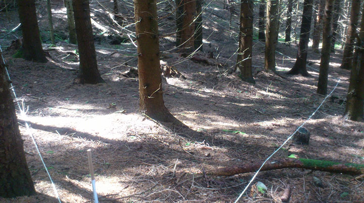
    Improvements dating from 2005 use a proprietary signal transmission structure that operates in the license-free Industry Scientific and Medical (ISM) band (2.4–2.4835GHz), known globally as the Wi-Fi band. Within this ISM band, the LocataLite design allows for the transmission of two frequencies, each modulated with two spatially-diverse PRN codes. From the beginning the driver for the Locata technology was to develop a centimeter-level accuracy positioning system that could complement, or replace, conventional RTK-GNSS in environments such as open-cut mines, deep valleys, heavily forested areas, urban and even indoor locations, where obstruction of satellite-based signals occurs.

    Leica Geosystems has been testing Locata in the Newmont Boddington Gold Mine (NBG) in Western Australia for several years. In 2006, NBG started installing Leica Geosystems high-precision GPS-based guidance systems for fleet management. The mine operators determined early on that as the pit grew deeper, they would need an alternative positioning system for these guidance systems to continue working for the life of the mine. In March 2012, Leica Geosystems deployed a world-first production version of its Jigsaw Positioning system, integrating GNSS+Locata, at the NBG mine.

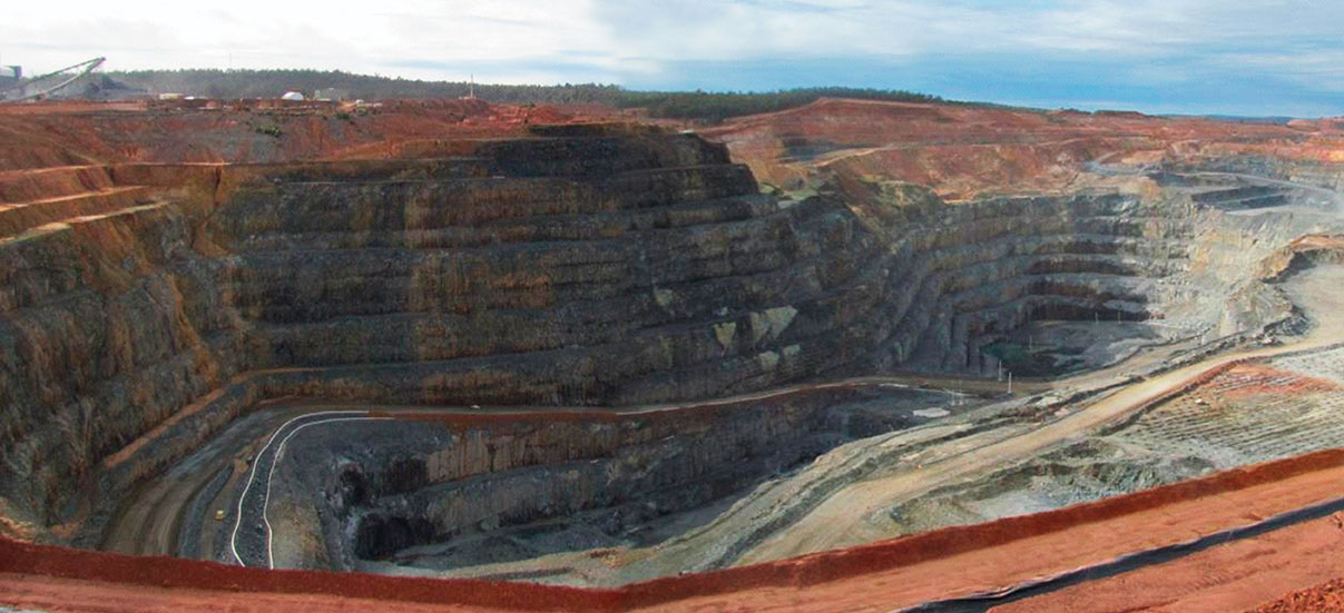
    Expected to become Australia’s largest gold producer, the mine consists of two pits (Figure 1). The North Pit at NBG is currently about 1 kilometer long, 600 meters wide, and now approaching 275 meters deep.

    Figure 1. Location of 12 LocataLites at NBG Mine.
    Figure 1. Location of 12 LocataLites at NBG Mine.
    Figure 2. The Newmont Boddington pit, 900 feet deep and going deeper all the time, creates difficulties for GNSS equipment positioning the mine’s heavy machinery.
    Figure 2. The Newmont Boddington pit, 900 feet deep and going deeper all the time, creates difficulties for GNSS equipment positioning the mine’s heavy machinery.

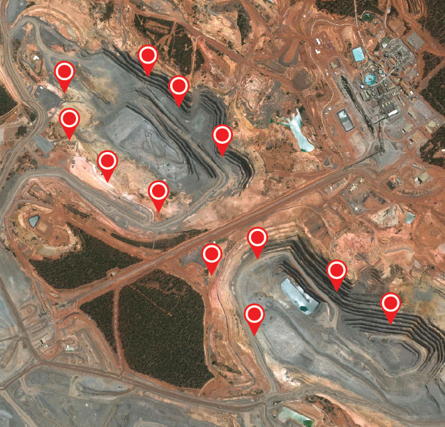
    A single LocataNet consisting of 12 LocataLites was deployed during April and May 2012 in an initial installation designed to cover both pits in the mine. The results presented here are taken from tests in the North Pit.

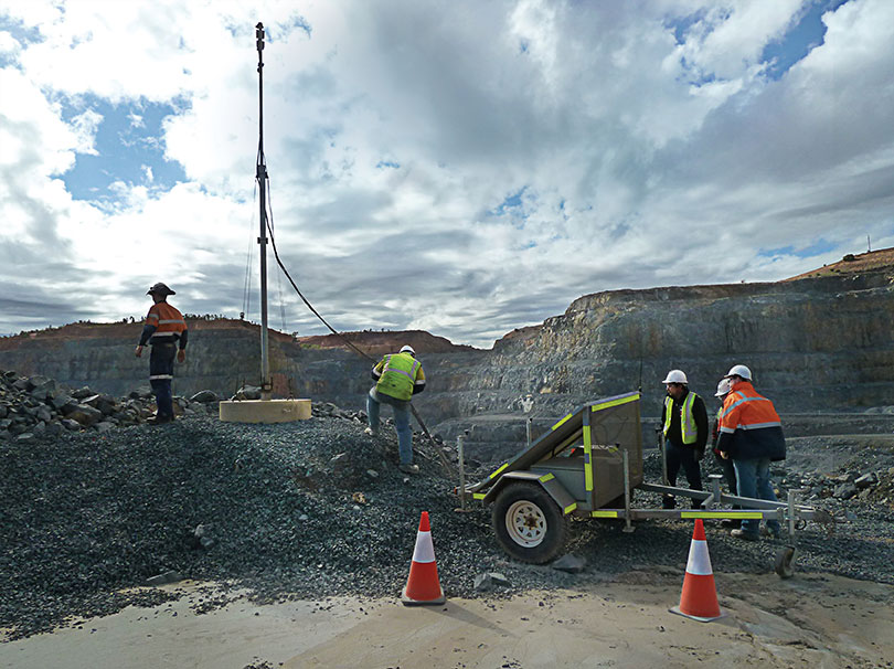
    Leica’s version of the LocataLite is solar-powered and designed to be placed in the best locations to achieve the maximum benefit. As no special consideration for the location of a transmitter base station is required, the LocataLites can be placed in areas on the rim of the pit or just above the machines operating in the pit floor. The only set-up requirement is that they are able to see at least one other LocataLite to synchronize their transmissions to around 1 nanosecond or better throughout the mine.

    Each Jps transmit tower has four small patch antennas mounted in an array. The uppermost is a GNSS antenna used to self-survey the top of the tower, and hence derive the positions of the other antennas below it on the tower. The Locata transmit 1 antenna is mounted directly under the GNSS antenna. The Locata receive antenna is directly under that, and the Locata transmit 2 antenna is around two meters lower down on the tower.

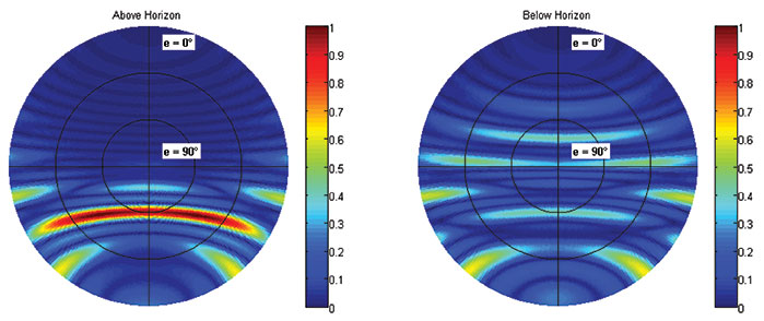
    All the antennas are separated by a known distance, and the LocataLite transmit antennas can be tilted down into the pit to maximize the signal broadcast into the area. Each LocataLite transmits four independent positioning signals, two signals from each transmit antenna. These signals provide a level of redundancy and greatly assist in the mitigation of multipath problems in the pit, thereby contributing to the robustness and reliability of the positioning solution.

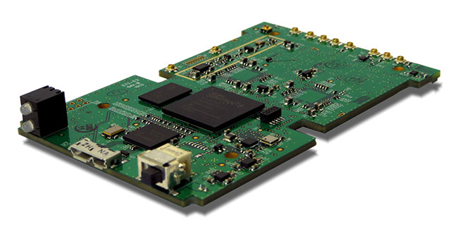
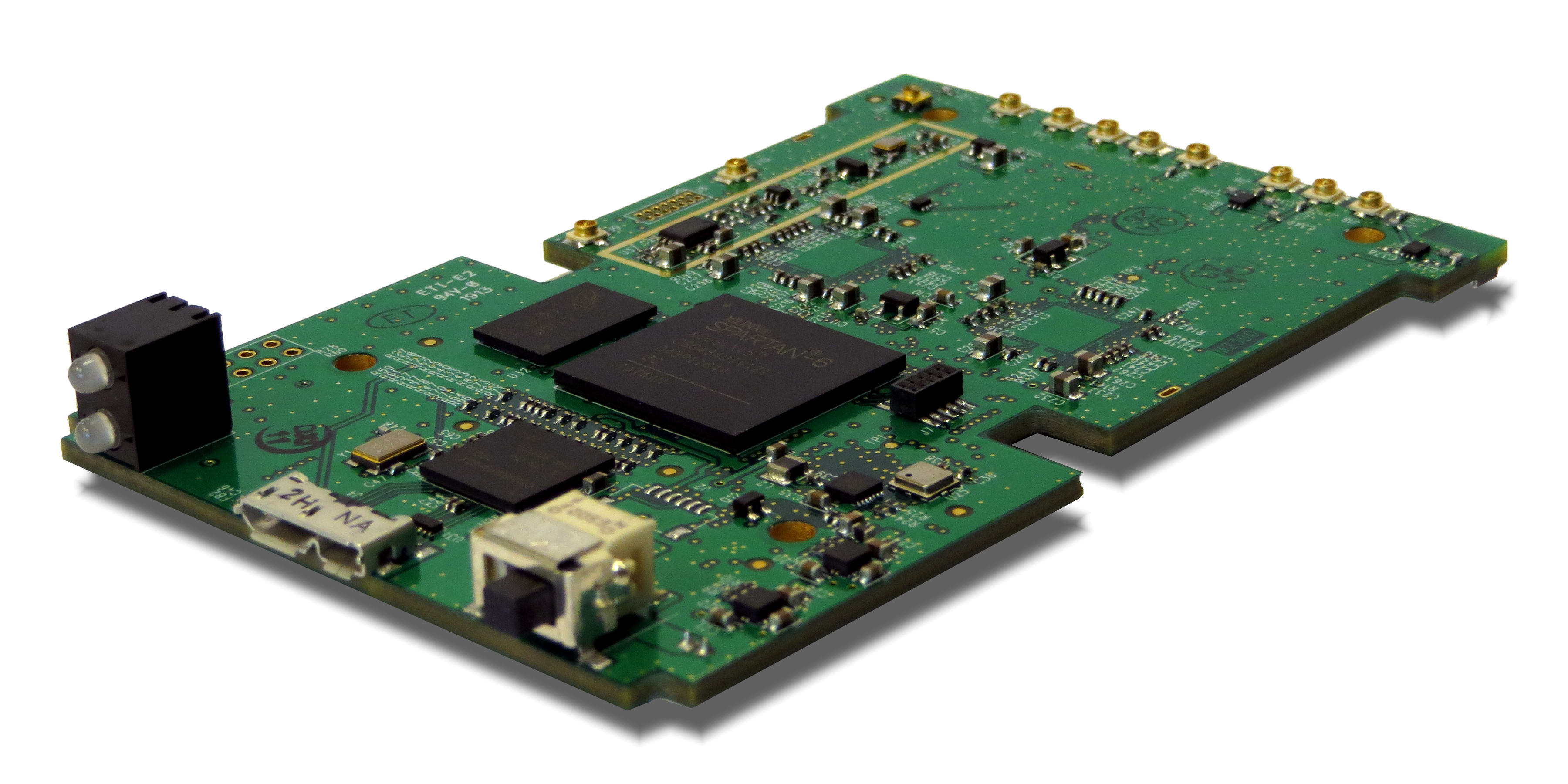
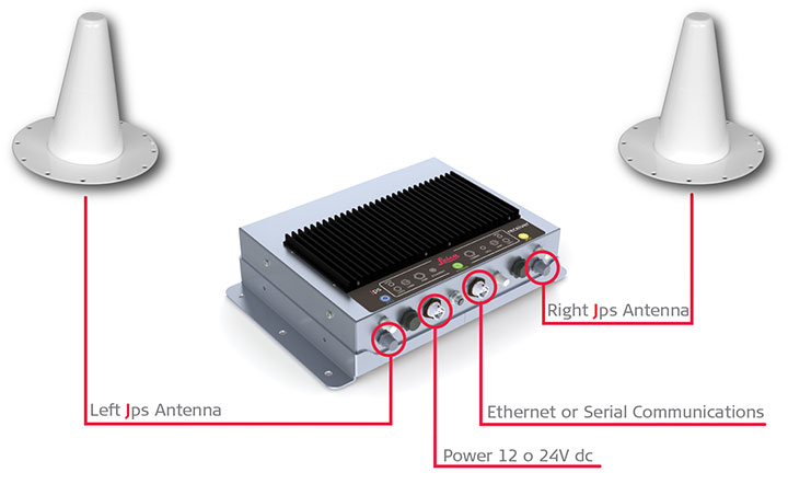
    Jps receivers were first installed on two production drill rigs in April 2012. Installation on drills was the highest priority because they are the machines at NBG that operate closest to pit walls and other obstructions, and therefore stood to benefit most from having more reliable positioning. Each Jps receiver incorporates two GNSS and two Locata receivers (Figure 3). One GNSS and Locata receiver pair is connected to a co-located antenna on one side of the machine and the other GNSS and Locata receiver pair is connected to the other co-located antenna. The GNSS receivers obtain their RTK corrections from an RTK base station. The Locata receivers do not require any corrections. The system uses the NMEA outputs from both pairs of receivers to determine the position and heading of the drill rig for navigation purposes.

    Figure 3. Jps receiver with integrated GNSS and Locata receivers and two receiver antennas.
    Figure 3. Jps receiver with integrated GNSS and Locata receivers and two receiver antennas.

    The goal of the Jps receiver is to improve the availability of high-accuracy RTK positions with fixed carrier phase integer ambiguities. The results presented here are therefore divided into three sections:

    • Improvements in availability over a two-month period for all the data in the North Pit.
    • Improvements in availability for an area in the pit where the GNSS savings are expressed in dollar terms.
    • Accuracy results achieved and maintained in this GNSS-degraded area.

    The performance results shown here are real-world samples of the system operating on drills at NBG. However, it will be appreciated that GNSS satellites are in constant motion, so GNSS-only position availability in different parts of the pit changes by the hour. The results therefore only apply to those drills in those positions in the pit at that time.

    Another drill a little distance away in the same pit could experience far better or far worse GNSS availability at exactly the same time.

    Overall Availability

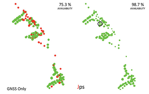
    Figure 4 shows the performance difference between using GNSS-only (left) and Jps GNSS+Locata (right). The data for these plots was recorded for the two drills that contained the Jps receiver in the North Pit during the months of April and May 2012. A green dot represents the time the receiver had a RTK fixed solution, and a red dot represents all other lower-quality position solutions — essentially when the receiver was unable to achieve the required RTK accuracy because of insufficient GNSS signals or geometry.

    Figure 4. Plots of availability and position quality in the North Pit at NBG for April and May 2012 for GNSS (left) and Jps (right). Green = RTK (fixed) solution, Red = all lesser quality solutions.
    Figure 4. Plots of availability and position quality in the North Pit at NBG for April and May 2012 for GNSS (left) and Jps (right). Green = RTK (fixed) solution, Red = all lesser quality solutions.

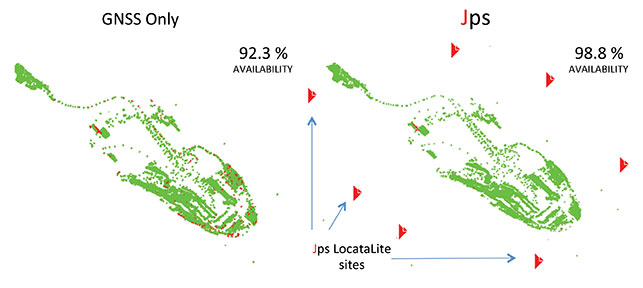
    Although the availability of GNSS-only RTK fixed position solutions was reasonably good over this entire area, being at the 92.3 percent level at that time, the Jps nevertheless provided a measurable improvement of 6.5 percent to availability, bringing it up to 98.8 percent. Considering that during those two months, the two drills spent a total of 72.24 operational days in the North Pit, this improvement equates to nearly 4.7 days or 112.7 hours of additional guidance availability.

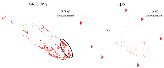
    Figure 5 highlights the low positional quality for the GNSS-only solutions and how Jps significantly improved the availability in areas of limited GNSS satellite visibility.

    Figure 5. Plots showing non-RTK quality positions, demonstrating that Jps can help reduce lesser-quality RTK solutions. (Performance in the circled area is highlighted in more detail in Figure 6.)
    Figure 5. Plots showing non-RTK quality positions, demonstrating that Jps can help reduce lesser-quality RTK solutions. (Performance in the circled area is highlighted in more detail in Figure 6.)

    Availability in Poor GNSS Visibility

    The ellipse in Figure 5 highlights a particular location in the North Pit where GNSS positioning consistently struggles due to the presence of the northern wall and to a lesser extent from the eastern wall. The integration of GNSS and Locata signals improved availability as shown in Figure 6, which in this case increased by 23.4 percent.

    Figure 6. Zoomed-in area where GNSS performance was poor between May 2 and May 4, 2012. The circled area shows where the accuracy tests were performed.
    Figure 6. Zoomed-in area where GNSS performance was poor between May 2 and May 4, 2012. The circled area shows where the accuracy tests were performed.

    As the machine downtime due to not having a RTK position costs the mine approximately U.S. $1000 per hour for each drill, the improvement in availability of 112.7 hours for just the two drills shown in Figure 5 over the two months equates to a savings of $112,700 in operational costs. This productivity increase is significant, considering that the GNSS-only availability in this case still seems relatively good at 92.3 percent. If the GNSS availability for those two months was more like 75 percent — as was the case shown in Figure 6 for the two days in May — then the cost savings become far greater, approaching nearly $400,000, for just two drills over two months. Even a small increase in productivity brings a significant financial benefit ($110,000 per hour) when all 11 drill rigs running in the mine are affected by loss of GNSS positioining availability, yet continue to operate with Jps.

    Today all 11 drills in the pits have been fitted with the Jps GNSS+Locata Receivers. As a point of reference to emphasize the level of operational savings: if the Jps had been fitted to all 11 drills during the April and May 2012 period shown in the above results, the cost savings at that time would have been on the order of $1,000,000. It is clear that the savings in production costs that can be gained from improving the availability to the fleet guidance system has a significant impact on the return-on-investment, potentially covering the installation costs within months of deployment. It should also be emphasized that as the pits get deeper, GNSS availability will only degrade further, and the evident production and dollar benefits of the integrated GNSS+Locata system become even larger.

    Relative Accuracy

    The above levels of improvement in availability are of no benefit if the position accuracy is not maintained within acceptable limits. In order to compare the relative accuracy between the two systems, a dataset was taken from the same data above (circle in Figure 6) when the machine was stationary.

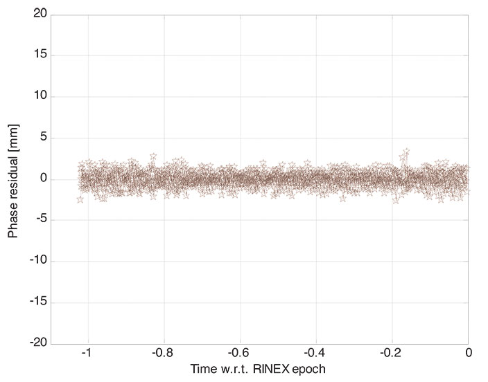
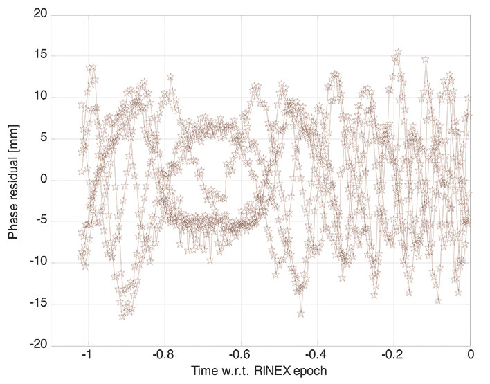
    The average position difference between the GNSS-only and Jps receivers for the hour-long dataset was 1.2 centimeters horizontally and 2.7 cm in the vertical component (Table 1). The spread of the position solutions for the two receivers were comparable in the horizontal, with Jps providing a slightly better horizontal RMS value due to the extra Locata signals being tracked and the stronger overall geometry. Additionally, Jps showed a better RMS in the vertical compared to GNSS-only.

    Table 1. Comparison of relative accuracy and RMS between the GNSS-only and GNSS+Locata solutions.
    Table 1. Comparison of relative accuracy and RMS between the GNSS-only and GNSS+Locata solutions.

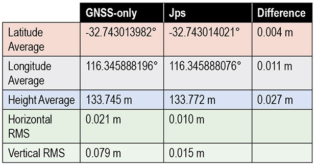
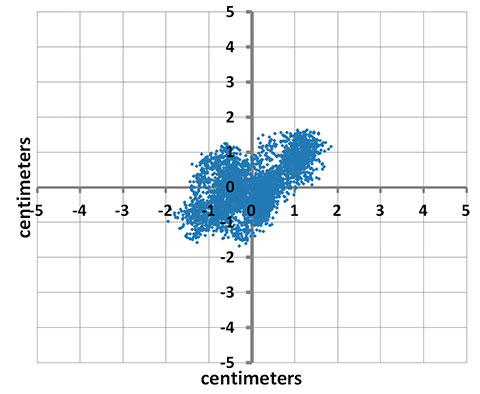
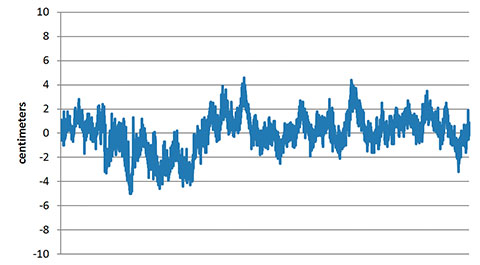
    Figure 7a shows the spread of horizontal positions for the Jps receiver, where 0,0 is the mean horizontal position during this time. Note that all the positions are grouped within +/-2 cm of the mean without any outliers. Figure 7b shows the corresponding spread in the vertical positions. These are well within the acceptable accuracy limits required by the machine guidance systems used at the mine.

    Figure 7A. Scatter plot of the positions from the Jps receiver over a period of over an hour.
    Figure 7A. Scatter plot of the positions from the Jps receiver over a period of over an hour.
    Figure 7B. Vertical error for same sample set as Figure 7a.
    Figure 7B. Vertical error for same sample set as Figure 7a.

    Concluding Remarks

    Based on the experiences at Newmont Boddington Gold, use of Jps has improved the operational availability of open-pit drilling machines by at least 6.5 percent by reducing the outages in 3D positioning caused by poor GNSS satellite visibility commonly associated with deep pits. When Jps is subjected to much harsher conditions closer to high walls, the Jps continues to perform and the improvement in availability compared to GNSS-only is more significant while still maintaining RTK-GNSS levels of accuracy. The additional availability achieved translates directly into cost savings in production for the mine.

    Acknowledgments

    The first author acknowledges the support on the Australian Research Council grants that have supported research into pseudolites and Locata:

    • LP0347427 “An Augmented-GPS Software Receiver for Indoor/Outdoor Positioning,”
    • LP0560910 “Network Design & Management of a Pseudolite and GPS Based Ubiquitous Positioning System,”
    • LP0668907 “Structural Deformation Monitoring Integrating a New Wireless Positioning Technology with GPS,”
    • DP0773929 “A Combined Inertial, Satellite & Terrestrial Signal Navigation Device for High Accuracy Positioning & Orientation of Underground Imaging Systems.”

    The authors also thank the many people that have contributed to the development of the Leica Jps product. The Leica Geosystems Machine Control Core and CAL teams in Brisbane and Switzerland, other Hexagon companies such as Antcom Corporation and NovAtel, the Locata team in Canberra and the United States, and the people at Newmont Boddington Gold that have gone out of their way to make this a success.


    Chris Rizos is a professor of geodesy and navigation at the University of New South Wales; president of the International Association of Geodesy; a member of the Executive and Governing Board of the International GNSS Service (IGS), and co-chair of the Multi-GNSS Asia Steering Committee.

    Nunzio Gambale is co-founder and CEO of Locata Corporation, and represents the team of engineers who invented and developed Locata.

    Brendon Lilly is the product manager for the Leica Jps product at Leica Geosystems Mining and has worked for more than 20 years in both software and hardware product development. He has a Ph.D. from Griffith University.

  • Expert Advice: Get Sporty

    Expert Advice: Get Sporty

    mountain bikers, with navigation device

    By Mark Sampson

    In recent years, the sporting world has seen an explosion in the use of GPS. You will rarely spot a runner or cyclist on the road without either a smartphone strapped to their arm or a dedicated GPS device clamped to their handlebars, tracking their every move.

    The amount of information that the modern sportsperson — from casual amateur to full-time professional — logs, analyzes, and shares is phenomenal. There are now dozens of ways of uploading data for the whole world to share and study.

    As more manufacturers come to this market with the hope of capturing a share of it, they face the challenge of effectively developing and then testing their devices. Among many factors to consider, new products must have capability for local constellations such as BeiDou, GLONASS, and QZSS, not just GPS alone. New market entrants won’t have the same budget as the established big players, and constantly traveling to China or Japan to try out a new gadget will escalate costs to an unsustainable degree.

    Then there’s the issue of getting out into the kind of environment in which you imagine your new sporting GPS device will be put to use. In many cases this will be remote: forests, hills, and mountains. Stepping outside to the office car park does not constitute a sufficient test for satellite acquisition and retention. Neither does simply driving the commute route home with it.

    A GPS simulator or replay device allows for bench testing, but such devices are expensive. They might not actually fulfill your testing requirements, either: a traditional GPS simulator outputs its scenarios based on constellation modeling, either as a perfect signal or one that has simulated multipath. But you need to genuinely know how your new product will operate through, say, a forest on a downhill mountain bike run, or during a city marathon through urban canyons, or on a trail under wet trees. Adventure sport participants want to record their achievements wherever they go.

    How do you obtain this kind of realistic scenario? It will require the use of a GNSS recorder, and in an ideal world you would lend it to someone who actually does some of this stuff. Perhaps one of your colleagues is an (insane) downhill skier — who better to capture exactly that type of data, which you can replay back in a nice warm lab?

    The trouble is that a person of this sporting ilk will be unwilling or unable to carry bulky equipment that weighs several kilos. It will slow them down, so a GNSS recorder that can be easily carried without affecting the sporting activity is essential. It has to be easy to use: self-contained, with a battery that will last a couple of hours, and with one big button to start and stop recording. The user shouldn’t need any training in its operation. And ideally, it won’t need a large ground-plane antenna to capture usable data; a well-designed unit will employ a sensitive GPS engine allowing for as complete a signal as possible to be logged through a standard passive antenna.

    Looking further afield, other industries will soon be seeking a device with this level of convenience. For instance, agricultural and automotive manufacturers want the ability to send test engineers out to record drive-cycle tests easily and in a variety of vehicles. Additional features, such as controlled area network (CAN) and inertial sensor logging, synchronized with the GNSS data, will also find favor.

    The nature of the simulation market is changing: increasing numbers of developers need not just a traditional constellation simulator, but rather a replay device that is feature-rich and that doesn’t cost the earth.
    Economies of scale will likely dictate the way that this develops, and GNSS simulation will no longer be the specialist and exclusive field it once was.


    Mark Sampson is the LabSat product manager for  RaceLogic, based in Buckingham, UK.

  • Spirent Demonstrates Solution That Helps Reduce GNSS Vulnerability

    Spirent Demonstrates Solution That Helps Reduce GNSS Vulnerability

    Spirent-Qascom

    Spirent Communications, a navigation and positioning systems testing company, has teamed up with Qascom, an expert in GNSS signal security and authentication, to develop a test tool that reproduces spoofing attacks in a controlled laboratory environment.

    The collaborative solution will be launched commercially later in 2013, and was previewed at ION GNSS+ in September in Nashville, Tennessee.

    The test bed will concurrently simulate legitimate GNSS constellations and spoofed or hoax signals. It will enable positioning systems manufacturers to improve their products’ resilience to hoax signals.

    As GNSS becomes increasingly embedded in modern infrastructure for application timing and device positioning, the impact of spoofing attacks becomes greater. From mobile telephony to Internet banking, GNSS timing signals are used in many key systems, and yet there is no requirement on GNSS equipment to demonstrate any degree of robustness to block or even detect malicious attacks that disrupt performance.

    “There is growing industry concern about the vulnerability of satellite navigation signals,” said John Pottle, Marketing Director of Spirent’s Positioning Division. “This will help the industry to create positioning systems that are more resilient to interference.”

    Hoax or spoofing attacks work by mimicking genuine GNSS signals, which mislead GNSS receivers. Often affected receivers do not recognize when they are receiving fake signals and continue to operate normally, but provide false time or position information. This new test tool helps to develop systems that will detect and counter spoofing attacks by providing a fully controllable laboratory based, non-radiated test solution to evaluate a receiver’s response to a range of spoofing attacks. The test tool controls the emulation of signals representing both the genuine GNSS signals and the false signals. This allows users to simulate a wide range of sophisticated attacks and monitor the response of the receiver under attack to then improve the resilience of the design against such attacks.

    For more information on threat detection and mitigation testing visit Spirent Booth #F during ION GNSS+, September 15-20 in Nashville, Tennessee.

  • Rockwell Collins Awarded Contract to Develop Secure Software-Defined Radio GNSS Receiver Capability

    Rockwell Collins has received a 2 million contract from the Air Force Research Laboratory (AFRL) to develop and demonstrate a secure software-defined radio (SDR) GNSS receiver capability.

    GNSS typically refers to equipment that can receive signals from multiple navigation satellite systems including GPS, GLONASS, Galileo, and the Chinese BeiDou system. By utilizing multiple available satellite signals, a GNSS receiver can provide improved navigation performance and signal availability.

    Hosted in a software-defined radio, this AFRL program will develop the security architecture required for the receiver equipment certifications. The arrival of modernized GPS signals and other constellations is changing the way the U.S. military accomplishes GNSS-based positioning, navigation and timing.

    “Rockwell Collins is actively researching GNSS capability as it applies to the U.S. and global customer base,” said John Borghese, vice president of the Rockwell Collins Advanced Technology Center. “We’re leveraging decades of GPS experience and leading edge security architectures to produce a navigation receiver that will meet global needs.”

  • Septentrio PolaRx2 Receiver Orbits Earth on Board TET-1 Satellite

    Septentrio PolaRx2 Receiver Orbits Earth on Board TET-1 Satellite

    The TET-1 Satellite has Septentrio on board. (Image: DLR)
    The TET-1 satellite has Septentrio on board. (Image: DLR)

    Septentrio announced today that a PolaRx2 receiver has reached more than 330 hours of successful operation on board “Technologie-Erprobungs-Träger 1” (TET-1), the first satellite of the German On-Orbit-Verification program. The Septentrio receiver is the backbone of the Navigation and Occultation Experiment (NOX) developed by German Aerospace Center (DLR). The purpose of the experiment is to prove the suitability of commercial-off-the-shelf (COTS) technology for use in space missions.

    The receiver provides GPS observations on the L1 and L2 frequencies, which are used for precise orbit determination and atmospheric sounding. The dual-frequency observations allow reconstructing the orbit of TET-1 with decimeter or better 3D accuracy. A dedicated antenna pointed into the anti-flight direction of the satellite is used to collect measurements during GPS radio occultations, where the signals are tracked through the Earth’s atmosphere.

    After the first activation on July 26, 2012, the receiver has operated flawlessly in the harsh environment 500 km above the Earth’s surface and has been unaffected so far by space radiation. The receiver demonstrates quick acquisition of GPS signals and tracks a sufficient number of satellites even under challenging visibility conditions. The short time-to-first-fix together with the high availability of position and timing information from the navigation solution make the PolaRx2 a very suitable receiver for space-borne applications.

    “We are proud to see a new illustration that our standard commercial receivers perform flawlessly even in the harshest circumstances,” said Peter Grognard, Septentrio’s founder and CEO. “Our customers benefit every day from the same high quality and robustness for their demanding industrial applications on earth ”

  • UNB Technology Space Launch Delayed

    UNB Technology Space Launch Delayed

    Update: Elon Musk, SpaceX’s CEO and chief designer, has posted an update on the status of the upcoming Falcon 9 launch on his Twitter account. “Will do another static fire of rocket to make sure all is good & AF [[Air Force]] needs to test ICBMs, so probable launch Sept 29/30,” Musk tweeted.

    “The static fire is scheduled for later this week, perhaps Wednesday, sources said. It will retest the Falcon 9 rocket after several problems cropped up during a hotfire of the launcher’s engines Thursday at Vandenberg Air Force Base, Calif.

    “The U.S. Air Force Western Range, which controls a network of tracking and communications assets based at Vandenberg, is busy for the next few weeks due to Minuteman ballistic missile testing.”


    The Falcon 9 rocket, with CASSIOPE inside its fairing, on the way to the launch pad at Vandenberg Air Force Base. (Photo credit: SpaceX).
    The Falcon 9 rocket, with CASSIOPE inside its fairing, on the way to the launch pad at Vandenberg Air Force Base. (Photo credit: SpaceX).

    A GPS instrument designed by University of New Brunswick scientists is scheduled to be launched into space aboard the SpaceX Falcon 9 rocket on September 15. The rocket will depart Vandenberg Air Force base in California as part of the CASSIOPE (Cascade Smallsat and Ionospheric Polar Explorer) mission.

    Dr. Richard Langley, GPS World Innovation editor and professor in geodesy and geomatics engineering at the University of New Brunswick, is a principal investigator behind the scientific portion of the CASSIOPE mission. Langley and his colleagues will monitor data from the GPS instrument, which is part of the Enhanced Polar Outflow Probe (e-POP) payload aboard the spacecraft.

    E-POP will continue the sequence of Canada’s orbiting space environment sensors, which began with Canada’s first satellite, Alouette 1, launched in 1962 to study the ionosphere. e-POP is, perhaps, the most extensive suite of sensors for studying the ionosphere/magnetosphere/thermosphere yet to be launched, and will provide Canadian and other scientists with the opportunity to better understand the impact and variability the sun has on the space environment — what we call “space weather.”

    The website SpaceFlight Now will be covering the launch.

    The research satellite CASSIOPE on a test platform at the Canadian Space Agency’s David Florida Laboratory. CASSIOPE hosts the GPS Attitude, Positioning, and Profiling instrument designed by GGE researchers. It is currently scheduled for launch in 2010. The four white antennas on the left-facing side of the spacecraft will be used to determine the position, velocity, and attitude of the spacecraft while the antenna on the upper side will be used to profile the ionosphere’s electron density. Photograph courtesy of MacDonald, Dettwiler and Associates Ltd.
    The research satellite CASSIOPE on a test platform at the Canadian Space Agency’s David Florida Laboratory. CASSIOPE hosts the GPS Attitude, Positioning, and Profiling instrument designed by GGE researchers. The four white antennas on the left-facing side of the spacecraft will be used to determine the position, velocity, and attitude of the spacecraft while the antenna on the upper side will be used to profile the ionosphere’s electron density. (Photograph courtesy of MacDonald, Dettwiler and Associates Ltd.)
  • Loctronix Offers Software-Defined Radio Module

    Loctronix Offers Software-Defined Radio Module

    Loctronix ASR-2300
    Loctronix ASR-2300

    Loctronix Corporation, a provider of unified positioning solutions for GNSS-challenged environments, is making available its new software-defined radio (SDR) module, the ASR-2300, for developing high-performance positioning, navigation and timing, and communication applications.

    The ASR-2300 will be on display September 16-19 at the Institute of Navigation annual meeting, ION GNSS+ 2013, in Nashville, Tennessee.

    “The ASR-2300 delivers advanced SDR capabilities in a small, mobile form-factor enabling developers to readily create and field complex SDR-based solutions. The module moves SDR out of the lab and into production, providing the critical piece for tapping advanced, multi-sensor/signals of opportunity for high-performance PNT,” stated Michael Mathews, Loctronix’ CEO and founder.

    According to Mathews, “The ASR-2300 is unique amongst the growing number of SDRs, having multiple, fully-integrated RF paths supporting reception of GNSS, cellular, ISM band, and UHF signals of opportunity. The ASR-2300 will benefit SDR developers working on demanding scientific, military, aerospace and commercial/industrial applications.”

    The ASR-2300 is a multiple-input and multiple-output (MIMO) transceiver module incorporating two wideband Field Programmable RF (FPRF) transceivers (300 MHz to 3.8 GHz) from Lime Microsystems, 10-axis accelerometer/gyro/compass/barometer sensors, and a large programmable FPGA capable of over 300 MiB/sec sustained communications with a host processor via USB 3.0 interface.  The module’s nine integrated RF path options and low size, weight, and power characteristics contribute to ease of integration and portability. Accommodating both internal 1 PPM TCXO or external frequency reference, multiple ASR-2300s can be inter-connected via an expansion port and/or UART interface, supporting real-time reception / transmission of 4, 6, 8 or more signals without the need for significant additional hardware.

    With on-board flash for storing developer customizable firmware and FPGA logic, the ASR-2300 can be configured to operate in a variety of different power profiles, maximizing battery life without requiring a host processor.  The modules will be factory-programmed with only the RF receiver capabilities enabled.  Developers can enable transmit functionality by modifying the firmware and waveforms.

    The A2300 Open Source Project at Myriad RF

    To encourage innovation in PNT and communications applications, Loctronix has partnered with Lime Microsystems to provide the source materials for the ASR-2300 module under open source licensing at the Myriad RF project.

    “The broad utility of the ASR-2300 makes it an ideal platform for prototyping and developing advanced applications in the communications and PNT markets. Developers can make their own boards using the documents and design database contained in the A2300 project and/or purchase hardware, development kits, support services, and licensed waveforms directly from Loctronix,” Mathews said.

    “Encouraging collaboration between the open source community and industry is a natural way to promote innovation and accelerate growth of SDR technology. We are delighted to partner with Loctronix to make their innovative ASR-2300 SDR design available to open source developers for creating advanced SDR applications,” said Lime Microsystems CEO Ebrahim Bushehri, Ph.D.

    The open-source software package includes basic drivers for Linux and Windows environments enabling both GNU Radio and embedded C/C++ developers to interface with the ASR-2300 module.  Developers can obtain source code and design documents for modifying the ASR-2300 to suit their own applications.

    The ASR-2300 will be available from Loctronix this November. Adaptors, antennas, and a housing kit will also be available that provide a variety of configuration options supporting bench-top testing to wearable, battery-operated field demonstrations.

  • Racelogic to Launch LabSat3 at ION GNSS+

    Racelogic to Launch LabSat3 at ION GNSS+

    Racelogic LabSat 3
    Racelogic LabSat 3

    LabSat, the GPS record, replay, and simulation brand produced by Racelogic in the UK, is about to be augmented with the introduction of LabSat3.

    The key feature of the new product is its simplicity. It is, essentially, a single-box device that incorporates a GPS record-and-replay system without the need for a laptop or PC. Racelogic has designed the LabSat3 with convenience at its core: it is small and light, allowing users to record GPS signals in any situation, the company said. It will also come with a pre-recorded library of worldwide scenarios to allow engineers to perform immediate bench testing.

    The new LabSat is able to record signals from GPS, GLONASS, Galileo, BeiDou, QZSS, and SBAS, with the top of the range models able to output two channels simultaneously. Both the recording and replay procedures are simple one-touch operations, with data being logged to an SD card.

    LabSat3 is compatible with scenarios generated with SatGen software for those that wish to create full simulations. Ethernet connectivity extends its potential to end-of-line testing where multiple units can be remotely controlled, with potentially large savings in production line testing times.

    LabSat3 is set to be launched at the ION GNSS+ exhibition in Nashville next week. Prices will start at $4,400. For further details, visit the LabSat website.

  • Averna, National Instruments Team on Recording and Playback of RF Signals

    AvernaRF
    Photo: Averna

    Averna, developer of test solutions and services for communications and electronics device-makers worldwide, now offers RF Studio for National Instruments Software Defined Radio Platform (USRP), converting the USRP into a portable and cost-effective RF system for the recording and playback of real-world GNSS signals.

    National Instruments USRP is an affordable, PC-hosted platform used with NI LabVIEW system design software to build powerful wireless communications systems for research and education, Averna said. RF Studio is Averna’s proprietary software platform designed to streamline work with real-world RF signals. It provides user-friendly modules for capturing, processing, analyzing, archiving, and playing back RF spectrum while also maintaining the signal-recording context.

    Working together, Averna and National Instruments teams developed RF Studio for the USRP, an innovative and portable solution to record and play back live RF environments to accelerate RF project work. RF Studio’s LabVIEW compatible plug-in support delivers great value to LabVIEW users as it gives them quick access to a rich toolset for their in-house applications, and supports additional capture sources and customized views.

    “RF Studio for the USRP is the only cost-effective and portable product on the market that offers the flexibility to cover a wide variety of use cases, thus making it a very competitive solution for general-purpose RF record and playback,” commented Brendan Wolfe, Director of Market Development for Averna. “We’ve been working very closely with the NI teams to bring this innovative solution to market, and we expect great success from this solution partnership.”

    RF Studio for the USRP offers these features:
    ·  Record and play back real-world RF signals, up to 40 MHz wide
    ·  Capture actual RF spectrum like FM, DAB, GPS, GLONASS, and cellular
    ·  Visualize and record weak signals with the Noise Figure view
    ·  Advance signal analysis with the Spectrum, Histogram, and Power views
    ·  Use simple RF-chain configuration tools to quickly detect and set up the recording environment
    ·  DriveView option: Log video, audio and NMEA data at the same time as recording RF

    “The combination of RF Studio and the USRP provides a flexible, affordable solution for RF record and playback. Now in addition to prototyping wireless communications systems in LabVIEW, users can test them by reproducing realistic RF environments in the lab,” said Erik Luther, Wireless Communications Group Manager for National Instruments.

    RF Studio for the USRP is available now to customers worldwide through National Instruments’ LabVIEW Tools Network.

  • Leica Camera Integrates u-blox GPS into M-System Series

    Swiss-based u-blox has been chosen by Leica Camera as provider of GPS technology for its premium M-System camera and accessory series.

    Leica, which makes high-end and professional cameras, has integrated u-blox’ NEO GPS module into its new Multifunctional Handgrip M. The geotagging feature injects location data directly into each photo’s Exif header (Exchangeable image file format), allowing photos to be filed and retrieved according to where they were taken. The accessory is compatible with the new flagship Leica-M rangefinder digital camera series.

    The Multifunction Handgrip M connects directly to a computer via an integrated USB socket, allowing full remote control of the camera and image access using the Leica Image Shuttle software package. The handgrip also facilitates the safe and steady handling of the camera, particularly when shooting with heavier telephoto lenses.

    The handgrip’s features include a supplementary flash connector, a socket for an external power supply, and a sync socket for studio flash systems. An optional supplementary power source is also available.

    “Leica focuses on providing the highest quality photographic equipment on the market,” said Stefan Daniel, director of product management at Leica Camera.“When a customer purchases a Leica, they realize they are making an investment in a robust, high-performance camera that delivers outstanding results. To meet these expectations, we design with only the best mechanics, optics and electronics. For global positioning, we chose u-blox.”

    “We are proud to have been selected for our GPS technology by such a prestigious brand as Leica,” said Jochen Steinhauer, u-blox sales manager. “When you pick up a Leica camera, you immediately see and feel the high quality of every component. It is designed for perfection, a philosophy that u-blox also follows in our design of the world’s highest-quality global positioning modules.”


  • The System: IRNSS Signal Close up

    IRNSS Signal Close up

    By Richard Langley, Steffen Thoelert, and Michael Meurer

    The spectrum of signals from IRNSS-1A, the first satellite in the Indian Regional Navigation Satellite System, as recorded by German Aerospace Center researchers in late July, appears to be consistent with a combination of BPSK(1) and BOC(5,2) modulation.

    Figure 1 shows that, centered at 1176.45 MHz, the signal has a single symmetrical main lobe and a number of side lobes characteristic of the signal structure that the Indian Space Research Organization (ISRO) announced would be used for IRNSS transmissions in the L-band. Figure 2 shows the corresponding IQ constellation diagram. Further analysis will be required to sleuth additional signal details as ISRO, so far, has not publicly released an IRNSS interface control document describing the signal structure in detail.

    Figure 1. Spectrum of IRNSS-1A L5 signal.
    Figure 1. Spectrum of IRNSS-1A L5 signal.
    Figure 2. IQ constellation diagram of IRNSS-1A L5 signal.
    Figure 2. IQ constellation diagram of IRNSS-1A L5 signal.

    The German scientists caution that “this is a very early snapshot of the current signal transmission and probably both the signal power and the signal quality will change and possibly improve during the in-orbit-testing phase of the satellite’s operation.

    Extra Life for IIRs, IIR-Ms

    U.S. Air Force engineers are testing on-orbit a technique to extend the life of the 19 GPS IIR and IIR-M satellites on orbit, roughly 60 percent of the current contellation.

    A new charging method may reduce the rate of satellite battery degradation, thereby extending satellite operational life. If the technique passes the test, the initiative could add a combined 20 years to the life of the satellites — saving the Air Force tens of millions of dollars in the process.

    Gen. William Shelton, commander of Air Force Space Command, credits Capt. Jacob Hempen of the Air Force’s 2nd Space Operations Squadron for the job. Capt. Hempen says in turn that Warren Hwang of the Aerospace Corporation originated the idea.

    When satellite solar panels are directly exposed to the Sun, they charge satellite batteries while continuing to power other operations onboard the space vehicle. When the satellite passes  into the Sun’s shadow behind the Earth, it runs on batteries. The batteries can be re- charged at variable rates. When some of the batteries are powered above a certain rate threshold, they can overheat, accelerating their natural rate of decay.

    Lowering battery charging rates could still enable the satellites to perform well while minimizing the rate of degradation. Hitting the optimum number called for some finely-honed calculations.

    The satellites were built by Lockheed Martin Space Systems, and the oldest still in operation was launched in 1997.

    They had an intial design life of eight years, which many have now well outlasted. If the technique proves out and is carefully applied across the board, it could conceivably fill in replenishment gaps equivalent more than two additional spacecraft — conceivably as much hundreds of millions of dollars in build and launch costs, postponed. In today’s budget environment, a postponement can be construed as equivalent to outright savings.

    System Briefs

    GLONASS Partial Make-Good. Russia will launch two GLONASS satellites later this year to make up for the loss of three satellites in the July 2 Proton rocket explosion. The first is scheduled for the beginning of September, and the second at the end of October. Both will rise aboard Soyuz carrier rockets, which have proven more reliable than the Protons. A constellation of 29 GLONASS satellites is now in orbit, with 24 spacecraft in operation, three spares, one in maintenance, and one in test flight phase.

    Meanwhile, plans to reduce GLONASS funding have alarmed at least some deputies of the Duma, the Russian state legislative body. Government officials have floated a plan to reduce funding of the space program in 2014 by 11.7 billion rubles ($355 million), by 13.5 billion rubles in 2015, and by 40 billion rubles in 2016. The federal space program of Russia for 2006-2015 already lacks 10.5 billion rubles funding, and this year there has been a 2.3-billion-ruble additional reduction in R&D. A Duma committee chairperson warned that this trend will “lead to the loss of confidence of the international community in the GLONASS system and, consequently, to a reduction in its use globally. Russia will lose a strategic global instrument of political and economic prestige.” The Duma has recommended that the government maintain funding of federal space programs.

    Galileo Satellites’ Trial By Noise. The first Galileo Full Operational Capability (FOC) satellite successfully completed acoustic testing in July, part of a full-scale test campaign at ESA’s ESTEC Test Centre in Noordwijk, the Netherlands.

    The satellite was placed in the Large European Acoustic Facility (LEAF), effectively the largest sound system in Europe. A quartet of noise horns embedded in a wall of the 11 x 9 x 16.4 meter test chamber generated an acoustic noise level of 140.7 decibels, about the same noise as standing 25 meters from a jet taking off, and intended to simulate the extreme environment experienced by a satellite atop a rocket about to fire itself off the launch pad.

    A second FOC satellite arrived at ESTEC on 9 August from manufacturer OHB in Bremen, Germany. It will undergo a similar acoustic testing and then a System Compatibility Test Campaign will linking it with the Galileo Control Centres in Germany and Italy and ground user receivers as if it were already in orbit.

    A total of 14 FOC satellites are being produced and then tested at ESTEC as an integral part of their path to orbit. A second work order of eight satellites has been given to OHB.

    GPS III Pathfinder. On July 19, Lockheed Martin delivered a full-sized, functional prototype of the next-generation GPS satellite to Cape Canaveral Air Force Station to test facilities and pre-launch processes in advance of the arrival of the first GPS III flight satellite.

    The GPS III Non-Flight Satellite Testbed (GNST) paves the way for the first flight GPS III satellite, expected to arrive at the Cape in 2014, ready for launch by in 2015.

    An innovative investment by the Air Force under the original GPS III development contract, the GNST has helped to identify and resolve development issues prior to integration and test of the first GPS III flight space vehicle (SV-01).

    Following the Air Force’s rigorous “back-to-basics” acquisition approach, the GNST has gone through the development, test and production process for the GPS III program first, significantly reducing risk for the flight vehicles, improving production predictability, increasing mission assurance and lowering overall program costs.

    Lockheed Martin is currently under contract for production of the first four GPS III satellites (SV 01–04), and has received advanced procurement funding for long-lead components for the fifth, sixth, seventh and eighth satellites (SV 05–08).

    GNSS Industry Survey. Here are the results of two questions asked about government and industry from the 2013 GNSS STATE OF THE INDUSTRY SURVEY.

    Is government committed to private industry in a time of drastic budget cuts? For more results from the 2013 GNSS STATE OF THE INDUSTRY SURVEY.
    Is government committed to private industry in a time of drastic budget cuts?
    Is industry actively making its concerns known to government?
    Is industry actively making its concerns known to government?


  • Innovation: Under Cover

    Innovation: Under Cover

    Synthetic-Aperture GNSS Signal Processing

    By Thomas Pany, Nico Falk, Bernhard Riedl, Carsten Stöber, Jón O. Winkel, and Franz-Josef Schimpl

    GPS World photo
    INNOVATION INSIGHTS by Richard Langley

    A SYNTHETIC APERTURE? WHAT’S THAT? Well, an aperture in optics is just a hole or opening through which light travels. Those of us into photography know that the amount of light reaching the camera’s imaging sensor is controlled by the shutter speed and the size of the lens opening or aperture (called the f-stop). And a correct combination of the aperture setting and shutter speed results in a correct exposure.  For an optical telescope, its aperture is the diameter of its main, light-gathering lens or mirror. A larger aperture gives a sharper and brighter view or image.

    In the radio part of the electromagnetic spectrum, the term aperture refers to the effective collecting (or transmitting) area of an antenna. The gain of the antenna is proportional to its aperture and its beamwidth or resolution is inversely proportional to it.

    Astronomers, whether using optical or radio telescopes, often seek higher and higher resolutions to see more detail in the objects they are investigating. Conventionally, that means larger and larger telescopes. However, there are limits to how large a single telescope can be constructed. But by combining the light or radio signals from two or more individual telescopes, one can synthesize a telescope with a diameter equal to the baseline(s) connecting those telescopes. The approach is known as interferometry. It was first tried in the optical domain by the American physicist Albert Michelson who used the technique to measure the diameter of the star Betelgeuse. Radio astronomers developed cable- and microwave-connected interferometers and subsequently they invented the technique of very long baseline interferometry (VLBI) where atomic-clock-stabilized radio signals are recorded on magnetic tape and played back through specially designed correlators to form an image. (VLBI has also been used by geodesists to precisely determine the baselines between pairs of radio telescopes even if they are on separate continents.)

    A similar approach is used in synthetic-aperture radar (SAR). Mounted on an aircraft or satellite, the SAR beam-forming antenna emits pulses of radio waves that are reflected from a target and then coherently combined. The different positions of the SAR, as it moves, synthesize an elongated aperture resulting in finer spatial resolution than would be obtained by a conventional antenna.

    But what has all of this got to do with GNSS? In this month’s column, we take a look at a novel GNSS signal-processing technique, which uses the principles of SAR to improve code and carrier-phase observations in degraded environments such as under forest canopy. The technique can simultaneously reject multipath signals while maximizing the direct line-of-sight signal power from a satellite. Along with a specially programmed software receiver, it uses either a single conventional antenna mounted, say, on a pedestrian’s backpack for GIS applications or a special rotating antenna for high-accuracy surveying. Want to learn more? Read on.


    “Innovation” is a regular feature that discusses advances in GPS technology andits applications as well as the fundamentals of GPS positioning. The column is coordinated by Richard Langley of the Department of Geodesy and Geomatics Engineering, University of New Brunswick. He welcomes comments and topic ideas.


    Over the past few years, we have been developing new GNSS receivers and antennas based on an innovative signal-processing scheme to significantly improve GNSS tracking reliability and accuracy under degraded signal conditions. It is based on the principles of synthetic-aperture radar. Like in a multi-antenna phased-array receiver, GNSS signals from different spatial locations are combined coherently forming an optimized synthetic antenna-gain pattern. Thereby, multipath signals can be rejected and the line-of-sight received signal power is maximized. This is especially beneficial in forests and in other degraded environments.

    The method is implemented in a real-time PC-based software receiver and works with GPS, GLONASS, and Galileo signals. Multiple frequencies are generally supported.

    The idea of synthetic-aperture processing is realized as a coherent summation of correlation values of each satellite over the so-called beam-forming interval. Each correlation value is multiplied with a phase factor. For example, the phase factor can be chosen to compensate for the relative antenna motion over the beam-forming interval and the resulting sum of the scaled correlation values represents a coherent correlation value maximizing the line-of-sight signal power. Simultaneously, signals arriving from other directions are partly eliminated.

    Two main difficulties arise in the synthetic-aperture processing. First, the clock jitter during the beam-forming interval must be precisely known. It can either be estimated based on data from all signals, or a stable oscillator can be used. In one of our setups, a modern oven-controlled crystal oscillator with an Allan variance of 0.5 × 10⁻¹³ at an averaging period of 1 second is used. Second, the precise relative motion of the antenna during the beam-forming interval must be known. Again it can be estimated if enough sufficiently clean signals are tracked. The antenna trajectory is estimated directly from the correlator values as shown later in this article. In more severely degraded environments, the antenna may be moved along a known trajectory. We are developing a rotating antenna displacement unit. (see FIGURE 1). The rotational unit targets forestry and indoor surveying applications. The relative motion of the antenna is measured with sub-millimeter accuracy.

    FIGURE 1. Artist’s impression of the synthetic-aperture GNSS system for surveying in a forest.
    FIGURE 1. Artist’s impression of the synthetic-aperture GNSS system for surveying in a forest.

    After beam-forming, the code pseudoranges and the carrier phases are extracted and used in a conventional way. That is, they are written into Receiver Independent Exchange (RINEX) format files and standard geodetic software can be used to evaluate them. In the case where the artificial movement antenna is used, the GNSS signal processing removes the known part of the movement from the observations, and the observations are then like those from a static antenna. As a result, common static positioning algorithms, including carrier-phase ambiguity fixing, can be applied. The presented method therefore prepares the path for GNSS surveying applications in new areas. An important point is the mechanical realization of the antenna movement. This has to be done in a cost-efficient and reliable way. Lubrication-free actuators are used together with magnetic displacement sensors. The sensors are synchronized to the software receiver front end with better than 1 millisecond accuracy. The rotating antenna uses slip rings to connect the antenna elements. The rotating antenna can also be used to map the received signal power as a function of elevation and azimuth angles. This is beneficial for researchers. For example, it could be used to estimate the direction of arrival of a spoofing signal or to determine which object causes multipath in an indoor environment. For the latter purpose, the rotating antenna can be equipped with left-hand and right-hand circularly polarized antennas on both ends of the rotating bar. The rotating antenna is mounted on a geodetic tripod. See Further Reading for reports of initial studies of the rotating antenna.

    Tracking Modes

    The synthetic-aperture tracking scheme can be extended to different user-motion schemes or sensor-aiding schemes allowing a wide range of applications. This is reflected in the algorithm implementation within the modular structure of the software receiver. The base module “µ-trajectory & Clock Estimator” in Figure 2 prepares the synthetic-aperture tracking scheme. Different implementations derive from this base class. Each derived module is used for a different user motion scheme and makes use of a different sensor.

    FIGURE 2. Different µ-trajectory motion estimators used by the synthetic-aperture processing.
    FIGURE 2. Different µ-trajectory motion estimators used by the synthetic-aperture processing.

    Basically, the modules differ in the way they estimate the relative antenna motion over the beam-forming interval. This relative motion is called the µ-trajectory. Usually the µ-trajectory covers time spans from a few hundreds of milliseconds to a few seconds.

    The µ-trajectories have the following characteristics:

    • The pedestrian motion estimator does not rely on any sensor measurements and fits a second-order polynomial into the user µ-trajectory of a walking pedestrian. A second-order polynomial is good for representing the motion for up to a quarter of a second.
    • The sensor input to the rotating antenna estimator is the relative angular displacement of the rotating antenna. The estimator estimates the absolute direction, which is stable in time. Thus the number of µ-trajectory parameters equals one.
    • The vertical antenna motion estimator retrieves the vertical position of the antenna and does not estimate any µ-trajectory parameters. Only clock parameters are estimated.
    • Finally, the inertial navigation estimator uses accelerometer and gyro measurements and estimates the 3D user motion. The µ-trajectory parameters consist of accelerometer biases, the gyro biases, attitude errors, and velocity errors. The estimation process is much more complex and exploits the timely correlation of the parameters.

    Signal Processing Algorithm

    Two kinds of (related) carrier-phase values occur in a GNSS receiver: the numerically controlled oscillator (NCO) internal carrier phase  ocarrot1  and the carrier phase pseudorange ocarrot, which is actually the output of the receiver in, for example, RINEX  format files. Both are a function of time t and when expressed in radians are related via Equation (1):

    Inno-eq1    (1)

    Here, fo denotes the receiver internal nominal intermediate frequency (IF) at which all signal processing takes place. The output carrier-phase pseudorange ocarrot is an estimate of the true carrier-phase pseudorange , which, in turn, relates to the geometric distance to the satellite by the following standard model:

    inno-eq2   (2)

    This model applies to each signal propagation path separately; that is, a separate model can be set up for the line-of-sight signal and for each multipath signal. In Equation (2), λ denotes the nominal carrier wavelength in meters, ρ(t) is the geometric distance in meters between transmitting and receiving antennas, fRF is the nominal carrier frequency in hertz, dtsat(t) and dtrec(t) are the satellite and receiver clock errors in seconds, N is the carrier-phase ambiguity, and T(t) contains atmospheric delays as well as any hardware delays in meters. Here, no measurement errors are included, because we are considering the relationship between true values.

    Defining now a reference epoch t0, we will describe a procedure to obtain an improved carrier-phase estimate  for this epoch using data from an interval [t0TBF, t0]. The beam-forming interval TBF can be chosen to be, for example, 0.2–2 seconds but should be significantly longer than the employed predetection integration time (the primary one, without beam forming).

    Correlator Modeling. In this sub-section, the relationships between phase, correlator values, and geometric distances will be established. These relationships apply for each propagation path individually. In the next section these relationships will be applied to the total received signal, which is the sum of all propagation paths plus thermal noise. To model the correlator output we assume that any effect of code or Doppler-frequency-shift misalignment on carrier-phase tracking can be neglected. This is reasonable if the antenna motion can be reasonably well predicted and this prediction is fed into the tracking loops as aiding information. Then the prompt correlator output is given as

    inno-eq3.   (3)

    Again, any noise contribution is not considered for the moment. Here a(t) denotes the signal amplitude and d(t) a possibly present navigation data bit. The carrier phase difference Δφ is given as

    Inno-eq4  (4)

    where φ(t) is the true carrier phase and φNCO(t) is the NCO carrier phase used for correlation.

    We now split the geometric line-of-sight distance into an absolute distance, the satellite movement and a relative distance:

    Inno-eq5  (5)

    For the example of the rotating antenna, t0 might be the epoch when the antenna is pointing in the north direction. The term ρ0(t0) is the conventional satellite-to-reference-point distance (for example, to the rotation center) and ρsat(t0,t) accounts for the satellite movement during the beam-forming interval.

    The term Δρµ(t) is the rotational movement and may depend on the parameter µ. The parameter µ represents, for the rotating antenna, the absolute heading but may represent more complex motion parameters. The absolute term ρ0(t0) is constant but unknown in the beam-forming interval. We assume that approximate coordinates are available and thus Δρµ(t) can be computed for a given set of µ (that is, the line-of-sight projection of the relative motion is assumed to be well predicted even with only approximate absolute coordinates). The same applies also to ρsat(t0,t).

    Let’s assume that the NCOs are controlled in a way that the satellite movement is captured as well as the satellite clock drift and the atmospheric delays:

    Inno-eq6. (6)

    Then

    Inno-eq7(7)

    and

    Inno-eq8.(8)

    Thus the correlator output depends on the absolute distance of the reference point to the satellite at t0, the relative motion of the antenna, the receiver clock error, the received amplitude and the broadcast navigation data bits. Satellite movement and satellite clock drift are absent.

    Let us now denote m as the index for the different satellites under consideration. The index k denotes correlation values obtained during the beam-forming interval at the epoch tk. Then:

    Inno-eq9.(9)

    If multiple signal reflections are received and if they are denoted by the indices m1, m2, … , then the correlator output is the sum of those:

    Inno-eq10.(10)

    For the following, m or m1 denotes the line-of-sight signal and mn with n > 1 denoting multipath signals.

    Estimation Principle. It seems natural to choose receiver clock parameters dtrec and trajectory parameters µ in a way that they optimally represent the receiver correlation values. This approach mimics the maximum likelihood principle. The estimated parameters are:

    Inno-eq11.(11)

    Data bits are also estimated in Equation (11). Once this minimization has been carried out, the parameters µ and dtrec are known as well as the data bits. The real-time implementation of Equation (11) is tricky. It is the optimization of a multi-dimensional function. Our implementation consists of several analytical simplifications as well as a highly efficient implementation in C code. The pedestrian estimator has been ported to a Compute-Unified-Device-Architecture-capable graphics processing unit exploiting its high parallelism.

    Equation (11) realizes a carrier-phase-based vector tracking approach and the whole µ-trajectory (not only positions or velocity values) is estimated at once from the correlation values. This optimally combines the signals from all satellites and frequencies. The method focuses on the line-of-sight signals as only line-of-sight signals coherently add up for the true set of µ-trajectory and clock parameters. On the other hand, multipath signals from different satellites are uncorrelated and don’t show a coherent maximum.

    Purified Correlator Values. The line-of-sight relative distance change Δρµm(t) due to the antenna motion is basically the projection of the µ-trajectory onto the line-of-sight. Multipath signals may arrive from different directions, and delatp  is the antenna motion projected onto the respective direction of arrival.

    Let the vector trident  denote the phase signature of the nth multipath signal of satellite m based on the assumed µ-trajectory parameters µ:

    Inno-eq12.(12)

    Projecting the correlator values that have been corrected by data bits and receiver clock error onto the line-of-sight direction yields:

    Inno-eq13. (13)

    The correlator values Q are called purified values as they are mostly free of multipath, provided a suitable antenna movement has been chosen. This is true if we assume a sufficient orthogonality of the line-of-sight signal to the multipath signals, and we can write:

    Inno-eq14.(14)

    where K is the number of primary correlation values within the beam-forming interval. The projection onto the line-of-sight phase signature is then

    Inno-eq15.(15)

    Thus the purified correlator values represent the unknown line-of-sight distance from the reference point to the satellite. Those values are used to compute the carrier pseudorange. The procedure can similarly also be applied for early and late correlators. The purified and projected correlation values represent the correlation function of the line-of-sight signal and are used to compute the code pseudorange.

    Block Diagram

    This section outlines the block diagram shown in Figure 3 to realize the synthetic-aperture processing. The signal processing is based on the code/Doppler vector-tracking mode of the software receiver.

    FIGURE 3. Synthetic-aperture signal processing.
    FIGURE 3. Synthetic-aperture signal processing.

    The scheme has not only to include the algorithms of the previous section but it has also to remove the known part of the motion (for the rotating antenna, say) from the output observations. In that case, the output RINEX observation files should refer to a certain static reference point. This is achieved by a two-step process.

    First, the known and predictable part of the motion is added to the NCO values. By doing that, the correlation process follows the antenna motion to a good approximation, and the antenna motion does not stress the tracking loop dynamics of the receiver. Furthermore, discriminator values are small and in the linear region of the discriminator. Second, the difference between the current antenna position and the reference point is projected onto the line-of-sight and is removed from the output pseudoranges and Doppler values. For further details on the processing steps of the block diagram, see the conference paper on which this article is based, listed in Further Reading.

    Pedestrian Estimator

    We tested the synthetic-aperture processing for pedestrians on a dedicated test trial and report the positing results in this section. These results are not final and are expected to improve as more GNSSs are included and general parameter tuning is performed.

    Test Area. To test the pedestrian estimator, we collected GPS L1 C/A-code and GLONASS G1 signals while walking through a dense coniferous forest. The trees were up to 30–40 meters high and are being harvested by a strong local lumber industry. The test was carried out in May 2012. We staked out a test course inside the forest and used terrestrial surveying techniques to get precise (centimeter accuracy) coordinates of the reference points. Figure 4 shows a triangular part of the test course.

    FIGURE 4. Triangular test course in a forest.
    FIGURE 4. Triangular test course in a forest.

    Measurement data was collected with a geodetic-quality GNSS antenna fixed to a backpack. This is a well-known style of surveying. We used a GNSS signal splitter and a commercial application-specific-integrated-circuit- (ASIC-) based high-sensitivity GNSS receiver to track the signals and to have some kind of benchmark. The algorithms of this ASIC-based receiver are not publicly known, but the performance is similar to other ASIC-based GNSS receivers inside forests.

    We came from the west, walked the triangular path five times, left to the north, came back from the north, walked the triangular path again five times clockwise, and left to the west. We note that the ASIC-based receiver shows a 3–5 meter-level accuracy with some outliers of more than 10 meters. We further note that the use of the geodetic antenna was critical to achieve this rather high accuracy inside the forest.

    µ-trajectory Estimation. As mentioned before, the pedestrian estimator uses a second-order polynomial to model the user motion over an interval of 0.2 seconds. If we stack the estimated µ-trajectories over multiple intervals, we get the relative motion of the user. An example of the estimated user motion outside (but near) the forest is shown in Figure 5.

    FIGURE 5. Estimated relative user trajectory over 5 seconds outside the forest; user walking horizontally.
    FIGURE 5. Estimated relative user trajectory over 5 seconds outside the forest; user walking horizontally.

    The figure clearly shows that the walking pattern is quite well estimated. An up/down movement of ~10 cm linked to the walking pattern is visible. Inside the forest, the walking pattern is visible but with less accuracy.

    Synthetic-Aperture Antenna Pattern. It is possible to estimate the synthetic antenna gain pattern for a given antenna movement (see “Synthetic Phased Array Antenna for Carrier/Code Multipath Mitigation” in Further Reading). The gain pattern is the sensitivity of the receiver/antenna system to signals coming from a certain direction. It depends on the known direction of the line-of-sight signal and is computed for each satellite individually. It adds to the normal pattern of the used antenna element.

    We assume that the system simply maximizes the line-of-sight signal power for an assumed satellite elevation of 45° and an azimuth of 135°. We model the pedestrian movement as horizontal with a constant speed of 1 meter per second, and an up/down movement of ± 7.5 centimeters with a period of 0.7 seconds. Employing a beam-forming interval of 2 seconds yields the synthetic antenna gain pattern of Figure 6.The pattern is symmetric to the walking direction. It shows that ground multipath is suppressed.

    FIGURE 6. Synthetic antenna aperture diagram for a walking user and beam-forming interval of 2 seconds.
    FIGURE 6. Synthetic antenna aperture diagram for a walking user and beam-forming interval of 2 seconds.

    Positioning Results. Our receiver implements a positioning filter based on stacking the estimated µ-trajectory segments. As already mentioned, the stacked µ-trajectory segments represent the relative movement of the user. GNSS code pseudorange observations are then used to get absolute coordinates. Basically, an extended Kalman filter is used to estimate a timely variable position offset to the stacked µ-trajectory segments. The Kalman filter employs a number of data-quality checks to eliminate coarse outliers. They are quite frequent in this hilly forested environment.

    The positioning results obtained are shown in Figure 7. They correspond to the same received GPS+GLONASS signal but three different beam-forming intervals (0.2, 1, and 2 seconds) have been used. The position output rate corresponds to the beam-forming interval. Blue markers correspond to the surveyed reference positions, and the yellow markers are estimates when the user is at those reference markers. For each marker, there are ten observations.

    FIGURE 7. Estimated user trajectory with 0.2, 1, and 2 seconds beam-forming interval (blue: surveyed reference markers).
    FIGURE 7. Estimated user trajectory with 0.2, 1, and 2 seconds beam-forming interval (blue: surveyed reference markers).

    The triangular walking path is clearly visible. We observe a bias of around 3 meters and a distance-root-mean-square of 1.2 meters if accounting for this bias (the values refer to the 2-second case). The reason for the bias has not yet been investigated. It could be due to ephemeris or ionospheric errors, but also possibly multipath reflections.

    For the short beam-forming interval of 0.2 seconds, we observe noisier walking paths, and we would also expect less accurate code observations. However, the code observation rate is highest in this case (5 Hz), and multipath errors tend to average out inside the Kalman filter. In contrast, the walking paths for the 1-second or 2-second case are straighter. The beam-forming seems to eliminate the multipath, and there are fewer but more precise observations.

    Artificial Motion Antennas

    The rotating antenna targets surveying applications. It fits standard geodetic equipment. The antenna is controlled by the software receiver, and the rotational information is synchronized to the received GNSS signal.

    Synthetic-Aperture Antenna Pattern. With the same methodology as referenced previously, it is possible to estimate the synthetic antenna gain pattern. We assume that the pattern simply maximizes the line-of-sight signal power for an assumed satellite elevation angle of 45° and an azimuth of 135°. We use a rotation radius of 50 cm. The antenna has a really high directivity, eliminating scattered signals from trees. The gain pattern is symmetric with respect to the horizon and ground multipath of perfectly flat ground would not be mitigated by the synthetic aperture. Ground multipath is only mitigated by the antenna element itself (for example, a small ground plane can be used). However, mostly the ground is not flat, and in that case the rotating antenna also mitigates the ground multipath.

    Results with a Simulator. The rotating antenna has been tested with simulated GNSS signals using an RF signal generator. The signal generator was configured to start with the antenna at rest, and at some point the antenna starts rotating with a speed of 15 revolutions per minute. Six GPS L1 C/A-code signals have been simulated.

    The signal-processing unit has to estimate the antenna state (static or rotating) and the north direction. The quality of the estimation can be visualized by comparing the complex argument of the prompt correlator values to the modeled correlator values. Two examples are shown in FIGURES 8 and 9. In Figure 8, the differences are at the millimeter level corresponding to the carrier-phase thermal noise. This indicates that the absolute heading and receiver clock parameters have been estimated to a high precision.

    FIGURE 8. Carrier-phase residuals for all satellites observed with the rotating antenna without multipath. Time is in seconds and all data contributing to the RINEX observation record has been considered.
    FIGURE 8. Carrier-phase residuals for all satellites observed with the rotating antenna without multipath. Time is in seconds and all data contributing to the RINEX observation record has been considered.
    FIGURE 9. Carrier-phase residuals for all satellites observed with the rotating antenna with multipath. Time is in seconds and all data contributing to the RINEX observation record has been considered.
    FIGURE 9. Carrier-phase residuals for all satellites observed with the rotating antenna with multipath. Time is in seconds and all data contributing to the RINEX observation record has been considered.

    If multipath from a reflection plane is present (see Figure 9), the phase residuals show the multipath reflection. For example, around t = -0.65 seconds in the figure, the antenna is moving parallel to the reflection plane and the phase residuals are constant over a short time span. As the distance of the antenna to the reflection plane changes, the phase residuals start to oscillate. Generally, the estimation of the absolute heading and of the receiver clock parameters works even with strong multipath signals, but the parameters are not as stable as in the multipath-free case.

    In the case when the antenna is rotating, signal processing has to remove the rotation from the code and carrier observations. To check if this elimination of the artificial motion is done correctly, we use carrier-smoothed code observations to compute a single-point-positioning solution. Only if the antenna is rotating can the system estimate the absolute heading and refer the observations to the rotation center. Before that point, the observations refer to the antenna position. The antenna position and the rotation center differ by the radius of 0.5 meters. Since the position is stable for t > 100 seconds, we conclude that the elimination of the artificial motion has been done correctly.

    Conclusion

    We are in the process of developing positioning solutions for degraded environments based on principles of synthetic-aperture processing. The tools target operational use as an end goal, supporting standard geodetic form factors (tripods) and the software receiver running on standard laptops, and producing data in standardized formats (such as RINEX or the National Marine Electronics Association (NMEA) standards).
    Acknowledgments

    The research leading to the results reported in this article received funding from the European Community’s Seventh Framework Programme (FP7/2007-2013) under grant agreement No. 287226. This support is gratefully acknowledged. It also received funding from the Upper Bavarian Administration Aerospace Support Program under the contract number 20-8-3410.2-14-2012 (FAUSST), which is also thankfully acknowledged. This article is based on the paper “Concept of Synthetic Aperture GNSS Signal Processing Under Canopy” presented at the European Navigation Conference 2013, held in Vienna, Austria, April 23–25, 2013.

    Manufacturer

    The research described in this article used an IFEN SX-NSR GNSS software receiver and an IFEN NavX-NCS RF signal generator. The rotating antenna displacement unit was designed and manufactured by Blickwinkel Design & Development.


    THOMAS PANY works for IFEN GmbH in Munich, Germany, as a senior research engineer in the GNSS receiver department. He also works as a lecturer (Priv.-Doz.) at the University of the Federal Armed Forces (FAF) Munich and for the University of Applied Science in Graz, Austria. His research interests include GNSS receivers, GNSS/INS integration, signal processing and GNSS science.

    NICO FALK received his diploma in electrical engineering from the University of Applied Sciences in Offenburg, Germany. Since then, he has worked for IFEN GmbH in the receiver technology department, focusing on signal processing, hardware, and field-programmable-gate-array development.

    BERNHARD RIEDL received his diploma in electrical engineering and information technology from the Technical University of Munich. Since 1994, he has been concerned with research in the field of real-time GNSS applications at the University FAF Munich, where he also received his Ph.D. In 2006, he joined IFEN GmbH, where he is working as the SX-NSR product manager.

    JON O. WINKEL is head of receiver technology at IFEN GmbH since 2001. He studied physics at the universities in Hamburg and Regensburg, Germany. He received a Ph.D. (Dr.-Ing.) from the University FAF Munich in 2003 on GNSS modeling and simulations.

    FRANZ-JOSEF SCHIMPL started his career as a mechanical engineer and designer at Wigl-Design while studying mechanical engineering. In 2002, he founded Blickwinkel Design & Development with a focus on prototyping and graphic design.


    FURTHER READING

    • Authors’ Conference Paper

    “Concept of Synthetic Aperture GNSS Signal Processing Under Canopy” by T. Pany, N. Falk, B. Riedl, C. Stöber, J. Winkel, and F.-J. Schimpl, Proceedings of ENC-GNSS 2013, the European Navigation Conference 2013, Vienna, Austria, April 23–25, 2013.

    • Other Publications on Synthetic-Aperture GNSS Signal Processing

    “Synthetic Aperture GPS Signal Processing: Concept and Feasibility Demonstration” by A. Soloviev, F. van Graas, S. Gunawardena, and M. Miller in Inside GNSS, Vol. 4, No. 3, May/June 2009, pp. 37–46. An extended version of the article is available online: http://www.insidegnss.com/node/1453  

    “Demonstration of a Synthetic Phased Array Antenna for Carrier/Code Multipath Mitigation” by T. Pany and B. Eissfeller in Proceedings of ION GNSS 2008, the 21st International Technical Meeting of The Institute of Navigation, Savannah, Georgia, September 16–19, 2008, pp. 663-668.

    “Synthetic Phased Array Antenna for Carrier/Code Multipath Mitigation” by T Pany, M. Paonni, and B. Eissfeller in Proceedings of ENC-GNSS 2008, the European Navigation Conference 2013, Toulouse, France, April 23–25, 2008.

    • Software Receiver

    Software GNSS Receiver: An Answer for Precise Positioning Research” by T. Pany, N. Falk, B. Riedl, T. Hartmann, G. Stangl, and C. Stöber in GPS World, Vol.  23, No. 9, September 2012, pp. 60–66.