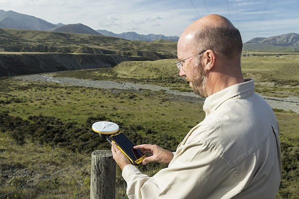
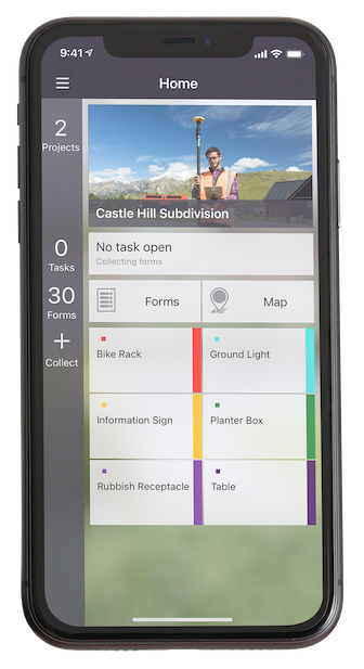
Trimble has released the Trimble TerraFlex Premium edition, a new tier of Trimble’s flagship geographic information system (GIS) data-collection software. The edition provides customers with offline GNSS corrections.
The new automated service works exclusively with Trimble GNSS receivers — including the Trimble DA2 receiver for the Trimble Catalyst positioning service — to provide high-accuracy GIS data capture in a wider range of locations and difficult GNSS environments than was previously possible.
TerraFlex users can increase the quality and speed of their data collection using offline GNSS corrections in situations where real-time services are intermittent or unavailable. Using the new service, all data from the field is automatically processed in the cloud without user intervention.
The most accurate real-time or offline processed position is stored for each feature, unlocking a high-productivity enhancement for all TerraFlex Premium subscribers.
Combining data-collection software and offline GNSS corrections into a single TerraFlex subscription simplifies both the workflow and the purchasing process for GIS organizations, from state and local governments to enterprise customers, including federal governments and utilities companies. This workflow to collect, process and deliver the most accurate and reliable positioning information reduces complicated manual processing steps and helps preserve data integrity.
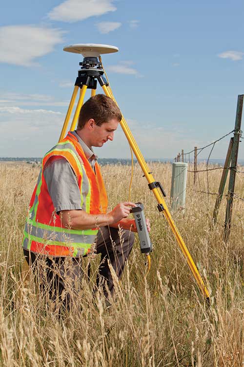
Photo: Trimble
Streamlined post-processing using TerraFlex offline GNSS corrections is also available to Esri ArcGIS users, with the new Trimble Terra Office add-in for the Esri ArcMap GIS application. The new add-in replaces both the Trimble Positions Desktop and Trimble TerraFlex Desktop add-ins and supports offline GNSS corrections as well as existing desktop post-processing workflows. Terra Office is available as a yearly subscription.
“With Trimble offline GNSS corrections, we’ve taken the manual steps out of post-processing and made it as effortless as possible,” said Gareth Gibson, marketing director, Trimble Mapping and GIS. “This workflow enables TerraFlex customers to expand the locations and environments in which they work while still achieving high-accuracy results, and all without needing to become a GNSS expert.”
The TerraFlex Premium edition subscription is available through Trimble Geospatial Distribution Partners.
The TerraFlex offline GNSS corrections service uses a network of community base stations, and is broadly available in North America, the United Kingdom, Europe, Australia and New Zealand.
The Trimble Terra Office add-in for Esri ArcMap software is available through Trimble Geospatial Distribution Partners.
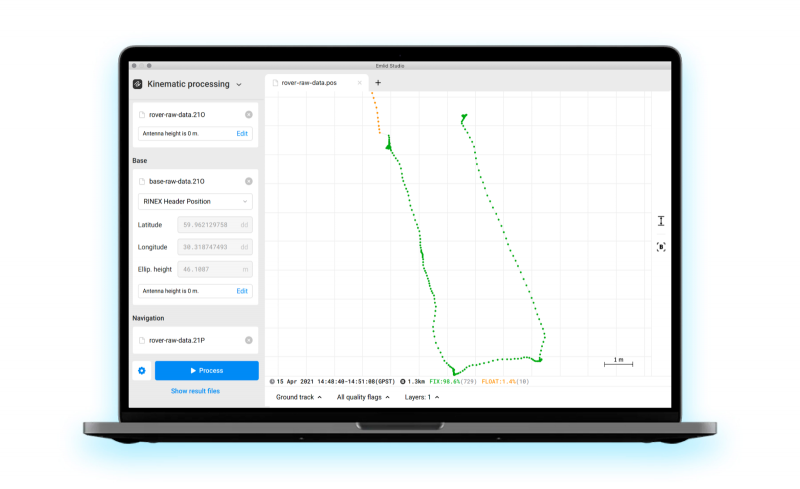
Emlid has released Emlid Studio, a new post-processed kinematic (PPK) application designed specifically for post-processing GNSS data. The app is free and available for Windows and Mac users.
Emlid Studio features a simple interface to make post-processing easy. The app allows users to convert raw GNSS logs into RINEX, post-process static and kinematic data, geotag images from drones (including DJI brand), and extract points from survey projects completed with Emlid’s ReachView 3 app.
With Emlid Studio, users can post-process data recorded with Emlid Reach receivers and other GNSS receivers or NTRIP services. Post-processing requires RINEX observation and navigation files. Raw data in UBX and RTCM3 format also can be used — Emlid Studio will automatically convert them into RINEX.
The post-processing workflow is straightforward. Users can receive precise positioning of a single point or track depending on the positioning mode. Users can simply add several RINEX files and enter the antenna height, click the Process button, and Emlid Studio will do the rest. Once the resulting position file is ready, the plot will show the result.
Another tool is available for the users of Reach receivers and the ReachView 3 app. The Stop & Go feature allows users to improve the coordinates of points collected in single or float modes.
Geotagging for drone mapping. Adding geotags to images’ EXIF data requires aerial photos and the POS file with the events. Emlid Studio also provides a chance to update data from the RTK drone in case of a float or single solution during a survey. A set of RINEX logs from a base and drone, an MRK file and images from the drone are dragged and dropped into specific file slots, providing result in seconds.
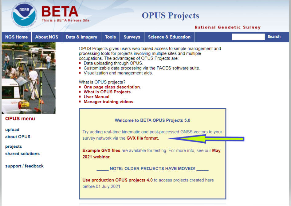
On Sept. 16, the National Geodetic Survey (NGS) released the latest beta version of OPUS, called Beta OPUS Projects 5.0. This version of OPUS now accepts real-time kinematic data and post-processed GNSS vectors from vendor software. See the box titled “Beta OPUS Projects 5.0 Webpage” on the website.
As stated in the announcement, NGS has developed a file format for submitted real-time kinematic (RTK) data and post-processed GNSS vectors from vendor software to NGS. It is denoted as GNSS Vector Exchange Format (GVX). This format enables NGS to incorporate the data into its GNSS processing routines.
This is similar to the original Receiver Independent Exchange Format (RINEX) developed for making post-processing more efficient when combining GNSS data from manufacturers outputting raw GPS data in varying file formats. In my opinion, this is a significant improvement to NGS’s OPUS web utility.
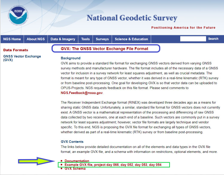
Users can obtain background information about the GVX file format by clicking the link GVX file format. More detailed information about the GVX format can be obtained by clicking on the Documentation link.
Basically, GVX is a standardized format for exchanging GNSS vectors derived from GNSS survey data using any manufacturer hardware and software results (see the box titled “Excerpt from Documentation of GVX”). NGS designed the format so that it included all of the necessary data (including metadata) of a GNSS vector for incorporation into a survey network for performing a least-squares adjustment.
To this end, this document proposes a new standardized file format known as the GNSS Vector Exchange Format (GVX). GVX aims to provide a standard format for exchanging GNSS vectors derived from varying GNSS survey methods and manufacturer hardware. The file format includes all of the necessary data of a GNSS vector for inclusion in a survey network for least squares adjustment, as well as metadata which describes the vector. The format is meant for any type of GNSS vector, whether it was derived in real-time or from baseline post-processing. GVX has been written in extensible markup language (XML). XML was chosen because it was designed to carry and store data in plain text format, it is easy to expand and/or upgrade to new operating systems, and it can be read by both humans and machines.
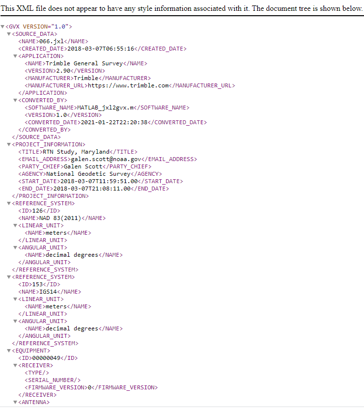
A sample GVX file can be obtained by clicking on the link titled “Example of GVX file, project day 066, day 052, day 053, day 054.” As NGS states in the documentation, the output can be read both by humans and machines. What’s important is that it can be read by machines so the information can be incorporated into software programs. GNSS vendors have all the information they need to generate the output file to enable users to import the data into OPUS Project 5.0. Users will have to contact their software providers to determine whether their software routines generate the GVX output files.
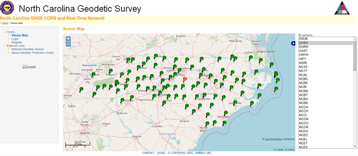
As I previously mentioned, this new option in OPUS Projects 5.0 is a significant improvement because many surveyors use RTK networks to obtain coordinates of marks. It will also facilitate the occupation of benchmarks with GNSS equipment to support the NGS 2022 Transformation tool. North Carolina, my home state, has a real-time network (RTN) that includes 96 GNSS CORS. (See the box titled “NC GNSS CORS and Real-Time Network.”) Currently, the North Carolina GNSS CORS and RTN has 4584 RTN service subscriptions.
I could not find a current list of public RTK networks in the United States, but I did locate a Jan. 7, 2014, GPS World article by Eric Gakstatter that provided a list of public RTK base stations in the country. It’s not up-to-date, but it highlights that, more than seven years ago, more than half of the U.S. states had some kind of public RTK network. I would like to update the table, so I’d appreciate receiving information on the status of any public RTK network. Please feel free to send me an email at [email protected].
California Real Time Network (CRTN) (single baseline). Plate Boundary Observatory. Single baseline.
Colorado
Mesa County (Trimble network) and Plate Boundary Observatory (single baseline).
Florida
Florida Department of Transportation. Leica network.
Idaho
Plate Boundary Observatory (single baseline).
Indiana
Indiana Department of Transportation. Leica network.
Iowa
Iowa Department of Transportation. Leica network.
Kentucky
Kentucky Transportation Cabinet. Trimble network.
Louisiana
Louisiana State University. Trimble network.
Maine
Maine Department of Transportation. Trimble network.
Massachusetts
Massachusetts Department of Transportation. Leica network.
Michigan
Michigan Department of Transportation. Leica network.
Minnesota
Department of Transportation. Trimble network.
Mississippi
University of Southern Mississippi. Trimble network.
Missouri
Missouri Department of Transportation. Trimble network.
Montana
Plate Boundary Observatory (single baseline).
Nevada
Washoe County. Trimble network. Las Vegas Valley Water District. Leica network. Plate Boundary Observatory (single baseline).
New Mexico
Plate Boundary Observatory (single baseline).
New York
New York Department of Transportation. Leica network.
North Carolina
N.C. Department of Environment and Natural Resources. Trimble network. $500 one-time sign-up fee.
Ohio
Ohio Department of Transportation. Trimble network.
Oregon
Oregon Department of Transportation. Leica network. Plate Boundary Observatory (single baseline).
South Carolina
South Carolina Geodetic Survey. Public but charges a usage fee. Trimble network.
Tennessee
Tennessee Department of Transportation. Public but charges a usage fee. Topcon network.
Texas
Texas Department of Transportation. Public but only available to TxDOT employees and TxDOT contractors. Trimble network.
Utah
Utah Automated Geographic Reference Center. Public but charges a usage fee. Trimble network. Plate Boundary Observatory (single baseline).
Vermont
Vermont Geodetic Survey. Trimble network.
Washington
Washington State Reference Network (Seattle Public Utilities). Trimble network. Public but charges a usage fee. Pierce County (Leica Network). Plate Boundary Observatory (single baseline).
West Virginia
West Virginia Department of Transportation. Trimble network.
Wisconsin
Wisconsin Department of Transportation. Trimble network.
Wyoming
Plate Boundary Observatory (single baseline).
Why do I believe that this new option in OPUS Projects 5.0 is so important? Because it facilitates the incorporation of accurate GNSS-derived ellipsoid and orthometric heights into the National Spatial Reference System (NSRS). With the development of improved algorithms, the results of coordinates computed using GNSS CORS/RTNs are more accurate today than ever before. During the last decade, there have been many studies analyzing GNSS data to estimate the accuracy values of coordinates from RTN data.
A study titled “Accuracy of GNSS Observations from Three Real-Time Networks in Maryland, USA” by Daniel Gillins, Jacob Heck, Galen Scott, Kevin Jordan and Ryan Hippenstiel presented at FIG Working Week 2019 in Hanoi, Vietnam, April 22–26, 2019, provided a comparative evaluation on the accuracy of three independent RTNs constructed with differing hardware and software. Their study was based on 486, 5-minute duration GPS + GLONASS network RTK (NRTK) observations. The results indicated that repeat NRTK vectors could be combined to meet 1 cm horizontally and 2 cm vertically (ellipsoid height) accuracies at 95%. confidence. See the box below. It should be noted that the repeat observations should be observed at different times of the day (for instance, separated by > 2–3 hours), as well as, in my opinion, if possible at least more than two different days.
A total of 486, 5-min duration, GPS+GLONASS NRTK observations were collected on nine bench marks distributed over a 4,000 square km area with rovers connected to three different RTNs in Maryland. Each RTN was developed with equipment and software from a different manufacturer, yet all three RTNs performed similarly in terms of accuracy. When differenced with coordinates from a static GNSS survey campaign, the horizontal and vertical RMSE of the NRTK-derived coordinates was 2.3 cm horizontally and 4.5 cm vertically at 95% confidence. Repetitive NRTK vectors on each baseline differed between ± 2.4 cm horizontally and ± 3.4 cm vertically at 95% confidence. As a final accuracy evaluation, hybrid survey networks consisting of repeat NRTK vectors and baseline solutions from post-processing static GPS data collected at RTN base stations and CORSs were adjusted by least squares. Prior to adjustment, the VCV matrices of the vectors were scaled by variance-component estimation. Adjustment of hybrid survey networks with four repeat NRTK vectors per bench mark produced network accuracies at 95% confidence for the adjusted coordinates at all bench marks less than 1 cm horizontally and 2 cm vertically (ellipsoid height).In addition to the benefits of using efficient and accurate NRTK vectors, the hybrid survey network approach makes use of redundant vectors for checking data and avoiding blunders. The approach also provides traceability because the NRTK vectors are tied to an RTN base station which is tied to CORS. Finally, these networks ensure the survey is referenced to the published coordinates of the CORSs which are held as constraints in the adjustment.
Lastly, I would like to remind users that only three months remain until the December 31, 2021, cutoff to submit GPS on Benchmarks data that NGS can guarantee will be analyzed to compute the initial set of 2020.0 Reference Epoch Coordinates (RECs) that will be released with the Modernized NSRS. This initial set of RECs is currently the only set that NGS can guarantee will be used to build the 2022 Transformation Tool. Once the transformation model is finalized, the NAVD 88 – NAPGD 2022 transformation values will be locked in and will not be updated as additional sets of RECs are computed. If you have questions or concerns about this cut-off date, please contact your NGS Regional Geodetic Advisor, or drop NGS a line at [email protected].
Beta OPUS Project 5.0 is a web-based tool that makes it easier to submit data to NGS. I would encourage NSRS users to occupy as many benchmarks with GNSS equipment and submit the data to NGS before the Dec. 31 deadline. Not only will these data help in improving the transformation model, but the marks will be included in the first computation of Reference Epoch Coordinates (RECs). You can obtain information about Reference Epoch Coordinates in NGS’s NOAA Technical Report NOS NGS 67 publication titled “Blueprint for the Modernized NSRS, Part 3: Working in the Modernized NSRS.” A future column will address the different types of coordinates that will be distributed by NGS with the modernized NSRS.
Applanix, a Trimble Company, has introduced new term licenses with full maintenance and support for its desktop post-processing software — POSPac Mobile Mapping Suite (POSPac MMS) and POSPac Unmanned Aerial Vehicles (POSPac UAV).
In addition, a new subscription for POSPac PP-RTX for UAV is also available.
The new licensing options lower the upfront investments required and enable customers to always have the newest features with updates included as part of the bundled maintenance and support.
The announcement was made at Intergeo 2021, a conference on geodesy, geoinformatics and land management, which took place this week in Hannover, Germany.
“The new licensing options for POSPac MMS and POSPac UAV provide our customers with maximum flexibility for acquiring full access to our industry-leading post-processing solutions. The options offer lower upfront initial investments and provide customers with full access to future releases and 24/7 customer support, as part of the included maintenance in the license agreements,” said Joe Hutton, Applanix’s Director of Inertial Technology and Airborne Products.
The new POSPac PP-RTX for UAV subscription is available with varying term lengths to accommodate user requirements. POSPac PP-RTX enables quick and easy data processing without a base station. The correction data is available within minutes after mission completion and requires a single button click in POSPac to launch. Customers will be able to process up to 30 minutes of dynamic data from the UAV platform.
The new licensing options and subscriptions are available now through the Applanix global sales channels.
BRING YOUR OWN DEVICE (BYOD) is not just an industry buzzword. It can change the way professional surveyors work every day. The idea of using a smartphone or tablet instead of a dedicated device is appealing. But is it good enough?
Surveyors and mappers are challenged with the arduous task of data collection that meets accuracy and precision standards and provides adequate attribute information for the project. Before the invention of the electronic data collector, handwritten notes in field books were the norm. Every note keeper’s style varied in content, neatness and thoroughness. Calculations for determining survey data values were completed longhand on paper and were very time consuming.
Like its personal computer counterpart, the electronic data collector was introduced in the late 1970s with minimal adoption by the average surveyor because of cost and complexity. Storage methods for the era included magnetic modules and tape; both forms of media were expensive and fragile with little storage for the cost.
Data collection was limited to numeric values only, with horizontal and vertical angles, slope distance, point number and point code being the extent of the information. Couple this process with the limited availability of printers and plotters capable of depicting the data for the surveyor’s use, and one can see why few practitioners invested in these systems.
iOS aerial viewer. (Screenshot: Tim Burch)
The 1980s and 1990s brought significant changes to surveying with the advancing technology of electronic computing and measuring. The introduction of robotic total stations, various methods of GNSS, and even leveling took advantage of significant computer power and measuring processes, and the data collector stayed in lockstep with the advancing instrumentation. Almost every equipment manufacturer developed their own proprietary data collector and software system because of the unique design and programming of their systems.
In the 2000s and later, third-party manufacturers began producing data collectors with advanced computing power and the ability to connect to varying brands of equipment. Most of the programming for these collectors are still proprietary in nature to this day.
Also during the 2000s, a new wave in mobile communications was taking place. Cellular phone and data signals were now being used to transmit an abundance of information between users.
The rapid development of handheld communication devices has led to the meteoric rise of two specific mobile operating systems: one by a radical startup that concentrated on dominating the search engine market, and the other by an avant garde computer company looking to expand its unique customer base.
By the end of the decade, the world had been introduced to the Android operating system by Google, and the iOS operating system by Apple. The combined market share for the two operating systems at press time was just under 98 percent of all mobile devices worldwide.
Trending Away from Proprietary Data Collectors
Android Point Info: Confirmation of collected data, including equipment and base station. (Screenshot: Tim Burch)
Because data collection by surveyors and mappers have traditionally been performed on proprietary systems designed and produced by equipment manufacturers for use with only their instruments, these collectors, while very powerful and robust, are costly for the equipment manufacturers to produce because of the limited market of surveyors and mappers.
Many suppliers, before the introduction of the iPhone and Android operating systems, attempted to adapt their data-collection platforms to wider recognized mobile operating systems (for example, Windows CE/Pocket PC/Mobile) on a bevy of mobile devices (HP/iPAQ, Sony Eriksson, HTC) with little success. Various versions of Windows are still being used today by GNSS equipment manufacturers’ proprietary data collectors, including Trimble, Hemisphere GNSS, Topcon and CHC Navigation.
However, the field of operating environments has become more crowded as technology continues to advance. The proliferation of Windows-based data collectors are now on the decline.
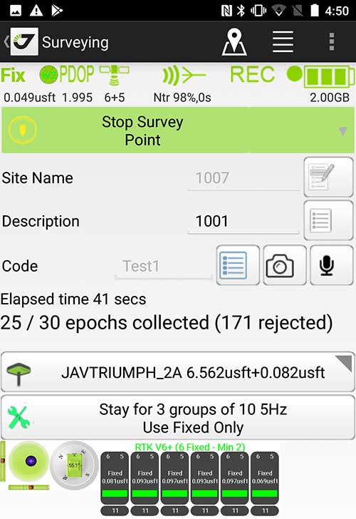
Survey Point: Status of survey data collection and GNSS engine signal reception. (Screenshot: Tim Burch)
Enter Android and iOS. Driving the decline of the previously popular Windows mobile platform is the rapid adoption of the iOS and Android operating systems. These two environments have also led to a substantial number of devices and applications for users.
Part of the reason for the speedy acceptance of the devices and operating systems has been the ease of programming. It is estimated that each operating system has more than two million applications in their respective online stores, with more being introduced daily.
Because of the proliferation of smartphones, nearly everyone is familiar with the look, feel and operation of touchscreen devices and their various applications. This familiarity is driving a new trend in data collection: the concept of “bring your own device” (otherwise known in IT security circles as “BYOD”). BYOD is being introduced by several surveying and mapping equipment manufacturers as an alternative to their proprietary data-collection devices.
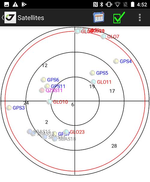
Sky Plot: Where the ‘birds’ are in the sky. (Screenshot: Tim Burch)
These manufacturers are pairing iOS and Android developers with their hardware and firmware specialists to create a user-friendly interface that will function on most of the most popular handheld devices on the market today. From Apple iPhones and iPads to Samsung Galaxy phones and tablets, these applications give the surveyor the best of two worlds — sophisticated data-collection capability on a well-known and reliable mobile operating system platform.
The Android platform is becoming especially popular in the handheld mapping market segment. Current users of this environment include Hemisphere GNSS, CHC Navigation, Tersus GNSS and Trimble.
The iOS applications, while not quite as prevalent as Android, are being embraced by several significant GNSS manufacturers, including JAVAD GNSS and Eos Positioning Systems.
These companies are creating iOS and Android apps that embrace the BYOD market, providing their users with affordability and creating a comfort level simply because of the familiarity of the device and its environment.
How Good Is It?
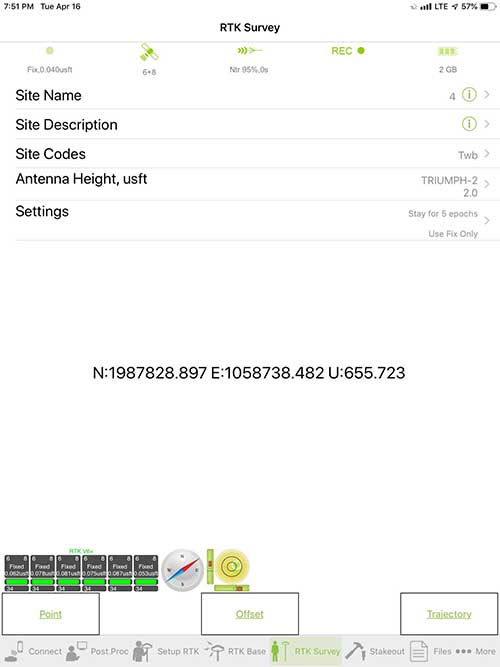
iOS Position. Status of survey data collection and GNSS engine signal reception. (Screenshot: Tim Burch)
For the surveyor to be satisfied with the operation, the collection process must be efficient, cost-effective and easy to use. For this explanation of key items within a well-rounded data-collection application, we are using the JAVAD Mobile Tools (now J-Mobile) application built specifically for the Android and iOS operating systems.
The Android system (Version 7.0) was installed on a rugged CAT S41 cellphone made Bullitt Group from the United Kingdom, while the iOS app was used on the author’s iPad Air 2 running Version 12.2. Both apps were utilized in conjunction with the JAVAD Triumph-2 GNSS receiver.
After putting both versions through trial testing and checking against values on known monuments, here is the results of our findings:
Receiver Setup. Visual reference for leveling and direction of GNSS receiver. (Screenshot: Tim Burch)
Data Organization. Easy to comprehend and flexible for most naming conventions.
Corrections and Sources. Easily connects to base receiver and radio or available NTRIP correction service for real-time network (RTN) capability.
Sky Plot. Because the Triumph-2 is equipped to receive most of the available satellites in service, the Sky Plot feature is beneficial to the user for assessing potential interference.
File Management, Import and Export. Covers the typical file management and transfer functions used by the surveyor.
RTK Survey Operations. Robust telemetry keeps the users informed of specific satellite data and correction status.
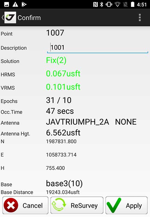
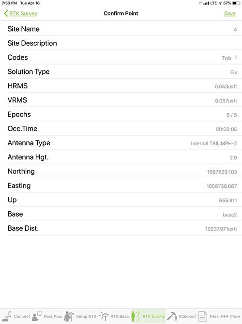
Point Confirmation. Survey point information with metadata and equipment listing. (Screenshot: Tim Burch)
Coordinate Systems. All standard coordinate systems are included with features to allow the user to customize their own systems.
Localization. Creation of a local coordinate system is a simple routine, providing strong quality checks for data integrity.
Lift and Tilt. This feature provides the user with a useful procedure to end data collection without the need to press a button. This feature significantly increases the user’s productivity.
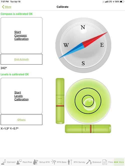
Compass and Level Calibration. With the Triumph-2 having an internal compass and level system, status of the receiver is graphically displayed to help the user keep a close watch on the accuracy of the survey point.
Survey Points and Linework. Most point naming systems and line-coding procedures are easily adapted. Total Station Point Transfer. The creation of control point files for transfer to total stations is simple and easy to use.
Stakeout. Graphical status screens provide the user with simple plotting capability of the desired stakeout point to increase efficiency and accuracy.
These apps are good at providing the surveyor with a solid tool for data collection and staking capability. They are especially good when paired with a real-time kinematic
(RTK) base station or NTRIP correction service.
But what happens when cell service is not readily available, or there are no published monument coordinates to establish site control? These apps have the surveyor covered for that situation as well.
Post-Processing (OPUS and DPOS)
Today’s surveyor works in an environment where geographic-based data is a key component to the services they render to their clients. While most of the world’s developed nations have access to cellular networks in which most GNSS receivers can communicate with an RTN providing corrective solutions, the places where this is not possible relies on other means of data correction.
In the U.S. we rely on OPUS (Online Post-Processing User System) to provide that service. But, as good as it is, it has limitations. Currently, it only utilizes GPS satellite data from the U.S. Department of Defense and is subject to sporadic government shutdowns.
Other services, from both public and private sources, are in place around the world to provide a service similar to OPUS. These include, but are not limited to:
AUSPOS. Geoscience Australia (free)
APPS. Jet Propulsion Laboratory at California Institute of Technology (free)
CSRS-PPP. Natural Resources Canada (free)
GAPS. University of New Brunswick (free)
magicGNSS. GMV (free)
Centerpoint RTX Post Processing. Trimble (free)
JAVAD Data Processing Service (DPOS). JAVAD (free, processes any JAVAD GNSS jps file)
These correction services utilize other satellite constellations (GLONASS, Galileo, BeiDou and QZSS) for their solutions and can provide additional coverage, depending on the location of the user. Because of these services, geographic-based data is at the fingertips of surveyors worldwide.
JAVAD’s DPOS system is has the ability to collect static survey data and send it to the proprietary service for establishing new coordinate values for base-station use. This process is a function of the app and can be completed in a few short steps.
Once the base station values are calculated, the surveyor can make use of this information for establishing a base station for correction broadcasting.
Do You Need a Base Station?
The establishment of RTNs has greatly enhanced surveying capability as cellular service has increased in coverage and speed. However, there are still instances and locales that do not allow for the reliable use of cell signals to provide those corrections accurately.
Various manufacturers’ tests have proven the accuracy of using an RTN subscription versus the traditional GNSS base and rover RTK setup. But cell-signal strength can be an Achilles heel, crippling those who choose not to set up a base station.
The UHF radio, even in its reduced power state from regulatory changes, is still more powerful and reliable than most cell services. 5G technology and coverage is anticipated to revolutionize cellular service, but it has yet to be realized.
Adaptation of the Industry
Other GNSS manufacturers (including NovAtel, Navcom, ComNav, Unicore, Emcore, Suzhou, TeleOrbit and Geneq) are producing receivers that can be adapted to a variety of existing data collectors and connect to iOS/Android mobile devices through various software developers.
The future of communications remains the smartphone or tablet device, with foldable units expected to be the next big thing.
As processors get more powerful, as chip memory becomes more abundant, and as more satellite constellations orbit in our sky, surveyors and their data collectors will continue to evolve. The future remains bright for technology and the surveyor has a front-row seat.
TIM BURCH is GPS World’s contributing editor for Survey. A professional land surveyor with more than 30 years of experience, he is director of surveying at SPACECO Inc. in the Chicago area. For several years he has been secretary and was recently named vice-president of the Board of Directors of the National Society of Professional Surveyors. He writes a bi-monthly column in the Survey Scene e-newsletter. Subscribe free at env-gpsworld-integration.kinsta.cloud/subscribe.
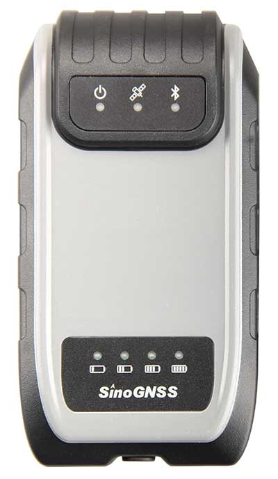
Receiver, Software Ready for Mobile
Photo: ComNav
ComNav receivers offer multiple data-collection device choices via Bluetooth connection, as well as an Android app.
For instance, the G200 provides centimeter-accuracy positioning to any connected mobile devices for RTK field surveying. It is able to delivery robust survey workflows with the SinoGNSS Android-based Survey Master, so that surveyors can collect quality high-accuracy positions no matter what mobile device they are using.
The G200 is a rugged, compact, wearable GNSS receiver. Combined with the high-performance SinoGNSS OEM board tracking GPS L1/L2, BeiDou B1/B2, GLONASS L1/L2, Galileo and QZSS, the G200 enables reliable high-precision GNSS performance for land survey tasks anywhere in the world.
TerraStar Gives Assist to RTK
Photo: Leica Geosystems
NovAtel offers several levels of corrections via its TerraStar service. For surveying applications, the RTK Assist service provides correction data to bridge surveyors through any real-time kinematic (RTK) correction outages. TerraStar services work on NovAtel’s OEM6 and OEM7 receivers..
RTK Assist, available on OEM6/OEM7 receivers, provides 20 minutes of RTK assistance, enabling surveyors to maintain centimeter-level accuracy. A higher service level, RTK Assist Pro, is available on OEM7 receivers. It provides unlimited RTK assistance with stand-alone centimeter-level positioning when RTK is not available.
Trimble Offers Web-Based Post-Processing
Photo: Trimble
Trimble’s CenterPoint RTX Post-Processing Service is a free, web-based solution that provides rigorous processing of GNSS data for users around the globe.
Powered by advanced algorithms for processing static observations, CenterPoint RTX Post-Processing supports data including GPS, GLONASS, Galileo, BeiDou and QZSS. With the service, users can upload GNSS data using Trimble formats or industry-standard RINEX 2 and RINEX 3. The service supports all dual-frequency GNSS receivers and more than 400 different antennas.
The post-processing service computes single-station static observation sessions ranging in length from 10 minutes up to 24 hours, with longer observation sessions recommended to produce the highest accuracy. Using data from the global RTX tracking network, the CenterPoint RTX Post-Processing service computes the position of the observed point with centimeter accuracy.
Results are delivered via email in ITRF coordinates at the current epoch and can be transformed to a fixed epoch by use of a standard tectonic-plate model.
Atlas Corrections Ready for BYOD
The Atlas GNSS global correction service, offered by Hemisphere GNSS, provides correction data for GPS, GLONASS, BeiDou and Galileo constellations. Its global L-band corrections allow for accuracies ranging from sub-meter to sub-decimeter levels. The network has more than 200 reference stations worldwide and covers virtually the entire globe.
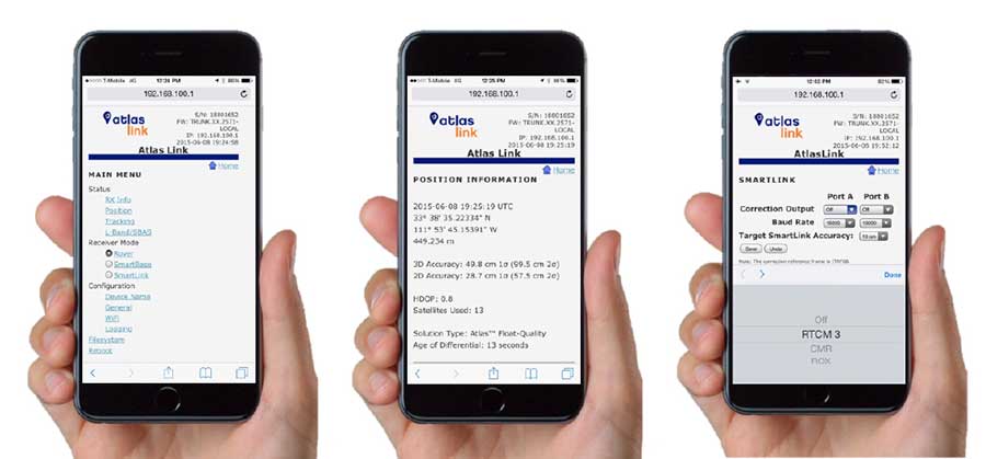
Examples of how the AtlasLink webUI looks on a smartphone. (Image: Hemisphere GNSS)
The Atlas platform was conceived to enable as many people as possible to have access to the correction service technology, either as an end-user or as part of their business. Several features are designed to enable customers who use non-Hemisphere positioning systems to have access to Atlas.
For instance, Hemisphere’s SmartLink technology allows an AtlasLink GNSS smart antenna to be used as an Atlas signal extension for any GNSS system compliant with open communication standards.
Hemisphere’s GNSS smart antennas including AtlasLink, A326, C321+ and S321+ offer a user-friendly web user interface (WebUI) that can be used to configure, monitor and manage the receiver from virtually any modern computing device, including computers, phones and tablets.
The Trimble CenterPoint RTX correction service, enabling centimeter-level absolute positioning around the world without the need for RTK reference-station infrastructure, is now available to many users, including integrators of professional high-precision equipment and consumer products such as in the automotive sector. Access is provided via a software library compatible with any GNSS device. The corrections now contain detailed integrity information for safety-critical applications.
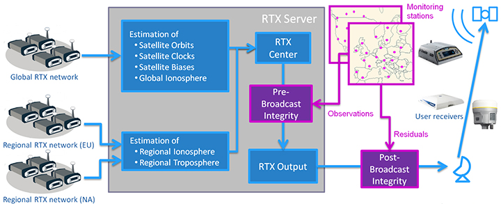
The RTX infrastructure is made up of approximately 120 globally distributed RTX reference stations. Receivers at these stations transmit measurement data at 1 Hz to the RTX server centers, where the correction data is computed. For redundancy purposes, multiple servers in the United States and Europe are operated. A failsafe architecture avoiding any single point of failure in the processing chain has produced a very high availability of corrections. Today the system supports GPS, GLONASS, Galileo, BeiDou and QZSS satellites. It is a multi-frequency system supporting two or more frequencies for each satellite system.
The correction stream is available to users using L-band signals broadcast via geostationary satellites and IP connections. The L-band transmitted RTX data stream uses a bandwidth of 600–2400 baud, and a highly compressed data format with a resolution of 1 millimeter, with an average latency of 8 seconds in L-band mode and 5 seconds in IP mode. The data stream is encrypted via an Advanced Encryption Standard (AES) with a key length of 256 bits to guarantee safe transmission. Data transmission integrity is assured with a 32-bit cyclic redundancy check attached to every message. The RTX correction stream provides information on satellite position, satellite clock, ionospheric and tropospheric models, and code and phase biases.
The orbit determination is done in real time using a reduced dynamic approach with dynamic models and exploiting the accuracy of the phase measurements after ambiguity fixing. Based on the computed orbits, the satellite clocks are estimated at 1 Hz, where integer ambiguity fixing is performed for the different satellite systems.
Next, a single-layer global ionospheric model is computed and represented through spherical harmonics. There are currently two areas with a denser network than the global network; these cover Europe and the mainland U.S. with more than 1,000 base stations. Using these stations, regional ionospheric and tropospheric models are computed, which then provide a fast convergence (RTX-Fast service).
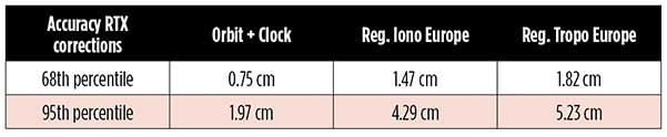
The satellite position and clock information has centimeter accuracy and allows the client to compute precise point positioning (PPP) with carrier-phase ambiguity resolution. Table 1 shows service accuracy.
Table 1. Accuracy of the RTX corrections from more than three years (June 2015–July 2018) of residuals computation in the European RTX-Fast network. (Table data: authors)
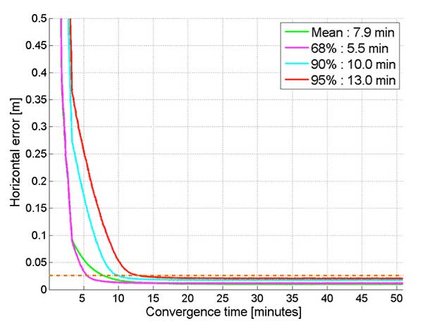
Once the ambiguities are resolved, the position solution is accurate to a few centimeters. The global RTX-Standard service provides convergence times of 7 minutes to 20 centimeters (cm) horizontal error (95%) and to 2.5 cm (95%) in 13 minutes as shown in Figure 2. The regional RTX-Fast service (U.S., Europe) provides convergence times of less than a minute with centimeter accuracy. The warmstart convergence time is approximately 13 seconds.
Figure 2. Global convergence of RTX out of 52 globally distributed stations covering one month of data. (Image: Trimble)
The accuracies specified are achievable with precise Trimble GNSS positioning hardware. For integration into non-Trimble devices, an RTX software library is offered, which gives the user real-time access to the individual data in the RTX correction stream. For use of this library in safety-critical systems such as advanced driving-assisted systems (ADAS) or semi-automated driving, this library was certified to follow the ASIL-B ISO 26262 standard and the automotive ASPICE standard. This library is available for easy integration into third-party applications.
In addition to the real-time RTX solution, a web-based post-processing solution is available for public use free of charge. It is possible to upload static Trimble or RINEX files to the server, post-process the measurement data, and retrieve a precise position in various coordinate frames.
Service integrity is continuously monitored at independent stations from the RTX tracking networks in Europe and the US. The integrity of the service is provided at the correction data domain. The integrity monitoring part of the RTX system minimizes the risk due to events such as unplanned satellite maneuvers or wrong broadcast ephemeris; satellite signal or clock anomalies; ionospheric storms; or problems in transmitting the RTX correction stream.
The monitoring stations compute phase observation residuals (with ambiguity fixing) using the station measurements and the received RTX corrections. These residuals represent the actual errors of the corrections as seen by the monitoring stations at the line-of-sight (Table 1). The thresholds at which corrections are considered as faulty are the following: 0.5 m + QI (quality indicator) for orbit + clock corrections and regional tropospheric models, and 1.0 m + QI for regional ionospheric models.
The integrity monitoring consists of two steps (Figure 1): a pre-broadcast check, where potentially faulty corrections are detected and filtered out before leaving the computing server, and a post-broadcast check, where additional errors in the transmission channel are detected and alarms are issued to the users.
Figure 1. Generation and transmission of RTX global and regional corrections, including pre- and post-broadcast integrity monitoring. (Image: Trimble)
Integrity flags and alarms are constantly inserted into the correction stream and output by the RTX client library. The integrity information notifies clients of the presence of integrity monitoring and provides timely alerts in case of detected correction-data integrity violations. The time-to-alert limit goals are 17 seconds for L-band transmission and 13 seconds for IP transmission for the RTX service.
The RTX corrections includes quality indicators. In particular, the quality indicator for the satellite clock includes a “DoNotUse” flag to indicate potential problems with the given satellite. This flag prevents the use of the satellite for positioning when received by the user. The quality indicators of the corrections are indeed a first integrity layer. In 2017 the pre-broadcast integrity monitoring was added to act as a second layer. In 2019, with the addition of the post-broadcast integrity monitoring, a third integrity layer was added to the RTX correction data stream.
The RTX system provides access to centimeter-level corrections allowing centimeter positioning on a global basis. RTX-Fast services are available in Europe and the U.S. with pre- and post-broadcast integrity monitoring currently being deployed.
The authors are engineers with Trimble Terrasat GmbH, Germany.
The latest software release for the SLAM-based NavVis M6 Indoor Mobile Mapping System (IMMS) automatically detects and removes point cloud artifacts, including moving objects in static scenes, the company said.
This image shows what an object looks like where the laser beam has hit an edge, before and after the algorithm has been applied. (Image: NavVis)
NavVis is a global provider of indoor spatial intelligence solutions. The latest IMMS release removes artifacts from point clouds during the post-processing of scan data.
Fringe points and dynamic objects are two common types of point cloud artifacts that affect all 3D laser scanning devices. Fringe points arise when a laser beam hits the edge of an object as well as its background. This scattered beam ultimately appears as a “fringe” around the edge of the object in the point cloud.
The second type of point cloud artifact results when dynamic objects, such as humans walking through a scan, are captured by the laser scanner and then appear as artifacts in the point cloud.
A point cloud before and after the algorithm has been applied to a dynamic object. (Image: NavVis)
According to the company, the NavVis M6 IMMS is a simultaneous localization and mapping (SLAM)-based system that uses laser scanners to capture a high volume of measurement points of an environment. As SLAM-based mobile mapping systems move through the environment while scanning it, objects are observed from multiple different angles and positions.
With the latest software update, the algorithms applied during the post-processing of scan data use those multiple observations to detect whether measurement points actually exist in the physical space. If it is determined that the point does not exist and is instead resulting from the laser beam hitting an edge or an object moving through the space, this point is automatically removed.
The result is a much cleaner, crisper point cloud that requires less clean up time in point cloud editing software and that is easier to use for applications such as BIM modeling, the company said.
“We have been working hard to develop a very precise SLAM technology that significantly improves the quality of point clouds captured by a mobile device,” said Georg Schroth, NavVis co-founder and CTO. “As this latest software feature shows, SLAM offers a lot of potential for laser scanning and AEC professionals who are looking for technology that not only speeds up the capture of data but also delivers high quality point clouds. We see a lot of potential in this technology and look forward to sharing future innovations.”
Sokkia introduced the latest addition to its GNSS integrated receiver line — the GRX3. According to the company, the GRX3 is designed to provide a smaller, lighter and fully integrated GNSS solution.
Photo: Sokkia
“The multi-constellation GRX3 receiver is built to offer a complete and versatile solution to provide best-in-class positioning performance for a wide variety of precision applications,” said Alok Srivastava, director of product management.
“Whether using the receiver for GNSS post-processed surveying, or RTK using wireless technologies including network RTK option with a cellular-equipped field computer, a SiteComm RTK rover, or paired with a Sokkia total station for fusion positioning, the GRX3 provides the most advanced and powerful GNSS technology available in a more compact and lightweight housing that can withstand the harshest of environmental conditions. Combine it with one of Sokkia’s data collectors and field software for maximum versatility and convenience, increasing fieldwork efficiency from start to finish.”
The receiver features Sokkia Tilt technology, which includes a 9-axis inertial measurement unit and ultra-compact eCompass designed to compensate for mis-leveled field measurements by as much as 15 degrees.
“The GRX3 is designed as a ‘future-proof’ solution with an advanced GNSS chipset with Universal Tracking Channels technology that automatically tracks signals from all available and planned constellations — including GPS, GLONASS, Galileo, Beidou, IRNSS, QZSS, SBAS,” Srivastava said.
The receiver has been tested to meet IP67 certification for protection against harsh environmental weather conditions.
DJI Phantom 4 Pro with Loki PPK system. (Photo: GeoCue)
GeoCue Group (via its wholly owned AirGon subsidiary) has completed the integration of the DJI Phantom 4 Pro RTK (P4R) into its AirGon Sensor Processing Suite (ASPSuite).
ASPSuite is a post-processing solution for GeoCue’s Loki direct geopositioning system for DJI and other manufacturer’s drones.
ASPSuite enables integration of the P4R with third-party L1/L2 GNSS base stations such as systems from Septentrio, Leica, Trimble, Topcon, CHC and others in a high accuracy post-process kinematic (PPK) workflow.
In addition to PPK processing, ASPSuite includes support for options often required in engineering-grade surveys such as:
vertical transforms (such as ellipsoid to country-specific geoids)
creation of and transformation between collection datums and local coordinate systems (site calibration)
application of antenna static and dynamic lever arm corrections
full support for Loki direct geopositioning systems.
The DJI D-RTK-2 base station (optionally available) for the P4R can only be used in RTK mode, and then only if it is being sited on a known location. The D-RTK-2 does not currently allow access to an observation file, preventing it from being stationed using an online positioning service such as OPUS, AUSPOS, Canadian Geodetic Survey services and so forth. An additional consideration in the integration into ASPSuite is that professional surveyors already have the survey kit that they need incorporated into this workflow.
GeoCue is offering camera calibration services for the P4R for customers who wish to do minimal or control-free high-accuracy mapping projects (the DJI “calibration” is an image de-warping algorithm, not a proper photogrammetric calibration). A test of a GeoCue-calibrated P4R using an OPUS-positioned base station and ASPSuite achieved about 4-cm horizontal and 5-cm vertical network accuracy (RMSE) with no ground control points.
Trimble has announced version 4.1 of Trimble Business Center office software that enables surveyors and geospatial professionals to simplify the creation of cadastral, GIS, infrastructure inspection and tunneling deliverables.
With the version 4.1 update, GNSS field data from GIS receivers (including the Trimble Geo 7X) can now be post-processed within Trimble Business Center to achieve high-quality feature locations. This allows enterprise-level organizations the flexibility to integrate both GIS and survey data within the same project environment and then link the high-quality locations directly to their Esri geodatabase.
Version 4.1 also provides seamless integration with Trimble Access 2018 field software to improve field-to-office productivity using new cloud-based data synchronization and workflow task management capabilities.
Version 4.1 adds new cadastral capabilities including proportioning, map checking and CAD drafting tools that streamline the creation of survey plans, plots and survey engineering digital deliverables.
For infrastructure inspection, construction as-built verification and volumetric applications, new projected surface tools enable professionals to analyze and compare data captured in the field against design. Point clouds from the Trimble SX10, Trimble VISION instruments, 3D laser scanners and unmanned aircraft system (UAS) platforms can be used for slope monitoring as well as to perform accurate volumetric, deformation and cut/fill analysis for retaining wall, dams and mining applications.
A new optional Tunneling Module enables survey and engineering professionals to simplify their workflow and improve productivity to meet time-sensitive deadlines for tunnel construction projects. Tunnel designs can be created and exchanged with Trimble Access field software, enabling customers to easily stakeout tunnel elements in the field and quickly produce as-built analysis and reports in the office.
After years of development and an intensive beta testing phase with key partners, Qinertia post-processing kinematic software is now being offered by SBG Systems.
Qinertia has been designed to help surveyors get the most of their surveys, according to SBG Systems.
After the mission, Qinertia gives access to offline real-time kinematic (RTK) corrections from more than 7,000 base stations in 164 countries — and always up-to-date. By creating a virtual base station near a project, the software delivers the highest level of accuracy without having to set up your own base station.
An advanced tight coupling algorithm has been designed by SBG Systems to deliver the highest accuracy and maximize RTK availability. Trajectory and orientation are greatly improved by processing inertial data and raw GNSS observables in forward and backward directions, especially in GNSS challenging environments (urban canyons, forest, etc.).
With advanced quality control indicators such as standard deviation, separations and GNSS quality feedback, Qinertia provides full understanding of a survey. With Qinertia, surveyors can quickly identify and solve issues such as mechanical installations or sensor alignment.
Qinertia has been designed to be easily integrated in a production workflow. It supports RINEX industry standard, and Septentrio, Novatel and Trimble native binary format.
A powerful ASCII export feature allows seamless integration with any third-party software. SBET and Google Earth are also supported for improved interoperability.
SBG Systems will demonstrate Qinertia, its in-house next-generation INS/GNSS post-processing software, at the Intergeo trade show, which takes place Sept. 26-28 in Berlin.
SBG Systems can be found is in Hall 1.1, stand C1.007.
For more than 10 years, SBG Systems has been designing inertial navigation systems from the internal inertial measurement unit (IMU) to filtering with GNSS data.
Designed for the surveying market, Qinertia is a fully in-house INS/GNSS post-processing kinematic (PPK) software. Whether the survey is made from a car, a UAV, a plane or a vessel, Qinertia will secure and enhance a surveyor’s acquisition, the company said.
The company will hold four live demonstration at its stand during Intergeo. The demonstrations will take place at 11 a.m. and 15 p.m. on both Tuesday, Sept. 26, and Wednesday, Sept. 27. There is no need to book to attend a demonstration, but please note that seats are limited.