Michibiki 2 will be launched aboard H-IIA Launch Vehicle No. 34 from Mitsubishi Heavy Industries Ltd., according to the Japan Aerospace Exploration Agency (JAXA). Launch time is tentatively set for 9:20 a.m. (Japan Standard Time) from Yoshinobu Launch Complex, JAXA’s Tanegashima Space Center. The exact date and time could vary, with a launch window planned for June 1-30.
NovAtel Inc. has entered an agreement with NEC Corporation to supply reference receiver products for use in the Quazi-Zenith Satellite System (QZSS). QZSS is Japan’s regional satellite-based augmentation system.
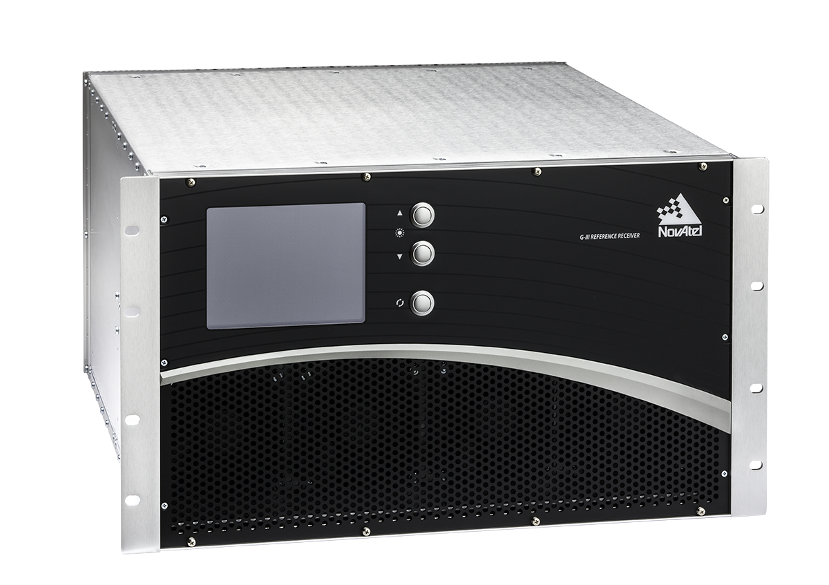
The NovAtel receivers to be used by QZSS are based on the company’s third-generation (G-III) family of reference receivers. Designed for integrity monitoring and reference measurement applications, the receivers track signals independently to provide precise code- and carrier-phase reference measurements as well as signal quality measurements and other integrity monitoring metrics. Housed in a 19-inch rack-mount enclosure with AC power supply and integral cooling fans, the G-III reference receivers provide continuous, reliable operation in a reference station environment, NovAtel said.
The G-III receiver platform has been customized to meet the needs of individual satellite networks. In addition to the QZSS G-III product, NovAtel supplies WAAS G-III reference receivers to the U.S. Federal Aviation Administration’s (FAA’s) modernized Wide Area Augmentation System (WAAS) network and IRNSS G-III reference receivers for the ground control segment of the Indian Regional Navigation Satellite System (IRNSS).
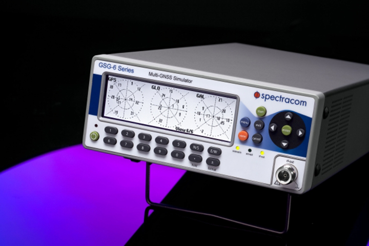
Spectracom’s GSG-6 Series multi-frequency GNSS signal simulator. Photo: Spectracom
Spectracom has added capability to simulate India’s global navigation satellite system, IRNSS, and Japan’s regional satellite system, QZSS, to its GSG-6 Series multi-frequency GNSS signal simulator. The simulator is designed to be field upgradeable to simulate all current and future GNSS constellations so current customers can benefit from these features without the need for a factory return in most cases.
“Spectracom understands the need for system developers and integrators to be compatible with various GNSS systems. Support for multiple constellations is a requirement in many markets and additional satellites add signal diversity for improved reliability,” said Spectracom Global Sales and Marketing Vice President Rohit Braggs. “Our easy-to-use, compact and affordable GNSS simulator can now be configured with IRNSS and QZSS capability in addition to the big four: GPS, GLONASS, BeiDou and Galileo. Our customers can buy what they need now and easily upgrade in the future, often times without a hardware upgrade.”
In anticipation of the deployment of new GNSS systems, Spectracom ensures that every GSG simulator that leaves the factory is tested for compliance with all L-band signal frequency and modulation specifications as defined in their ICDs, the company said.
The Series 6 multi-frequency simulator is fully capable of all four bands of any system: L1 / E1 / B1; L2 / L2C; L5 / E5 / B2; and E6 / B3.
“As we have seen with our recent roll-out of Beidou and Galileo signal compatibility, when the need for new signals arise, we will offer those capabilities with a simple upgrade path,” Braggs said. “This ensures our customer’s investment is always protected.”
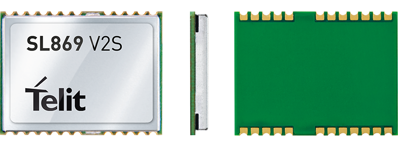
The Jupiter SL869-V2S GPS module. Photo: Telit Wireless Solutions
Telit Wireless Solutions, a global provider of high-quality machine-to-machine (M2M) modules and services, today debuted the Jupiter SL869-V2S GPS module, designed for easy migration between a full-GNSS solution for top-ranked applications and a simple GPS-only solution for less demanding applications.
The Jupiter SL869 V2S supports GPS as well as QZSS constellations and is ROM based. Geo-location data is delivered using NMEA protocol through a standard UART port. It supports ephemeris file injection (A-GPS) as well as Satellite Based Augmentation System (SBAS) for increased position accuracy. Its onboard software engine is able to locally predict ephemeris three days in advance starting from ephemeris data broadcast by GNSS satellites, received by the module and stored in the host flash memory.
Key benefits include:
Pin-to-pin compatibility with JN3/xL869 family
Same protocol used in SL869 V2
Straightforward migration between full-GNSS solutions and GPS-only solutions
SBAS support, for increased position accuracy
Assisted GPS
The SL869 V2S can replace the JN3, SL869 or SL869 V2 — allowing customers to design once and interchangeably mount the appropriate solution depending on the required features. The xL869 is Telit’s GNSS unified form-factor family, which allows customers to select among different GNSS technologies and feature sets. Modules in this family are offered in a 16 x 12.2 mm, 24-pad, LCC package.
“The new SL869 V2S module is designed to be easily swapped with other xL869 modules for enhanced simplicity and scalability,” said Taneli Tuurnala, CEO of Telit GNSS Solutions. “It is an ideal example of how buying a module from Telit enables our customers to avert the need to keep track of the latest chipset technology on their own. We keep them on top of the best available technology, pre-packaged in a module that is easy to replace as needed, without having to redesign their entire application to stay up to date.”
The Japan News is reporting that the Japanese Committee on the National Space Policy has compiled a draft proposal that includes increasing the number of quasi-zenith satellites (QZSS), Japan’s satellite navigation system, from the current single satellite to a total of four.
Currently, Japan is operating only one quasi-zenith satellite, named Michibiki.
The increase would be made to strengthen Japan’s overall surveillance systems, in light of developments such as China’s maritime expansion. “China’s high-pressure maritime advances have become a menace to the security of countries in Asia. Continued vigilance is also required against North Korea’s missile launches and nuclear weapons development program,” according an editorial published by The Japan News.
The additional QZSS satellites would presumably supplement Japan’s surveillance satellites with positioning information. Japan currently has four information-gathering satellites, which lack the flexibility to boost the accuracy of ground surveillance activities and swiftly grasp movements of objects such as vessels at sea.
“For surveillance activities, acquisition of high-precision positioning information using space technology is also important. Only the global positioning system (GPS) run by the United States is currently reliable for this purpose,” the editorial said.
A four-satellite QZSS system will allow positioning surveillance of all regions around the clock. Based on the proposal, the government is expected to revise the Basic Plan on Space Policy within the year.
The proposal also stipulates that the country should aim to operate seven quasi-zenith satellites as early as possible, which would allow stable management of the system, according to The Japan News.
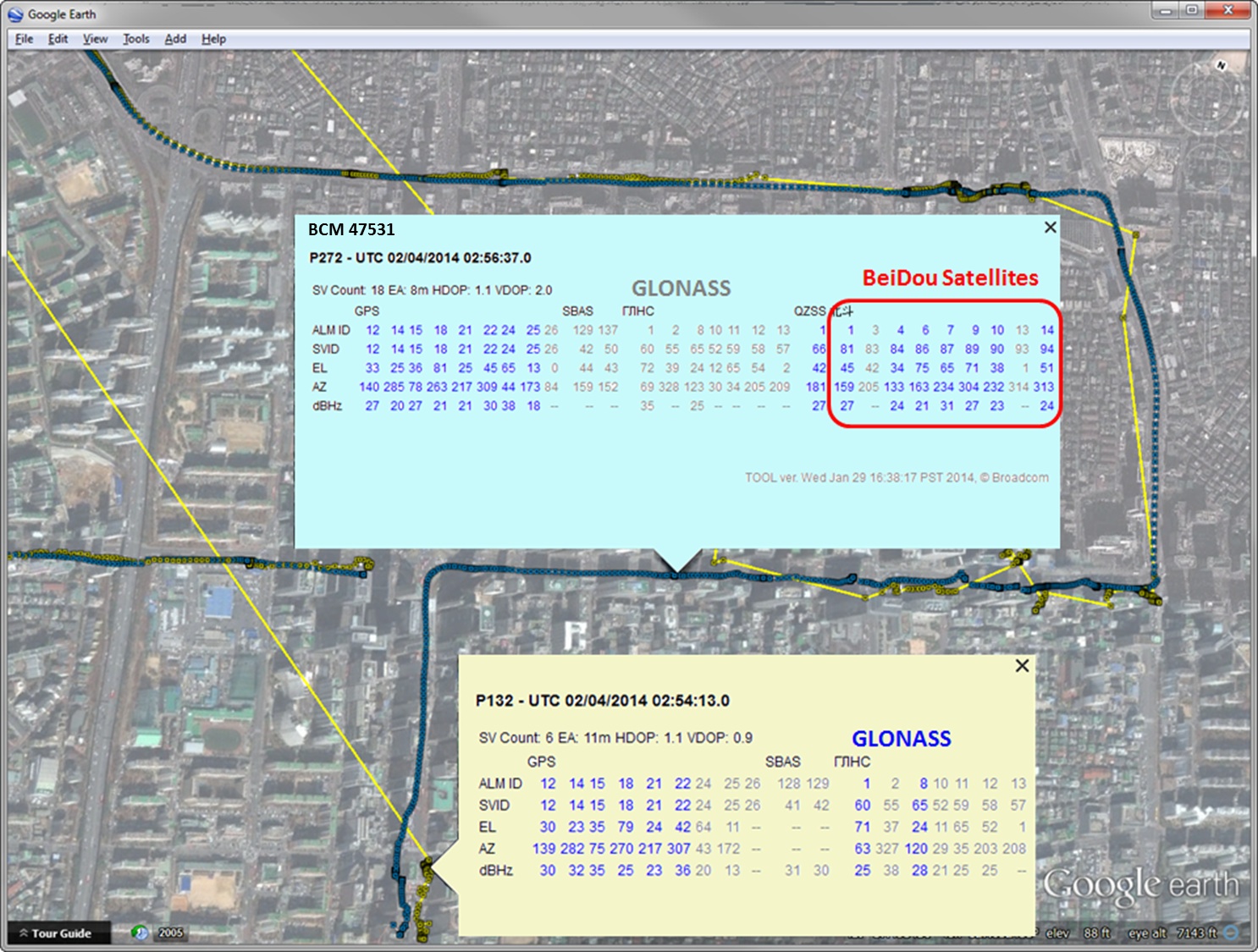
Yesterday we posted news of an 11-hour downtime for the full GLONASS constellation, due to an upload of bad ephemerides. Coincidentally, during that 11-hour period, the mass-market chip company Broadcom was conducting multi-constellation receiver tests in Asia. Frank van Diggelen, Broadcom’s chief GNSS scientist and vice president says, “We have definitive data to show how a multi-constellation receiver survives such an outage.”
Here are the pictures, and the story they tell.
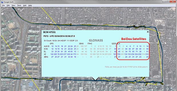
Test data coincident with the GLONASS ephemeris disruption of April 1 and 2 showing conclusively how a GPS/GLONASS/QZSS/BEIDOU receiver survives the complete disruption of one of the constellations.
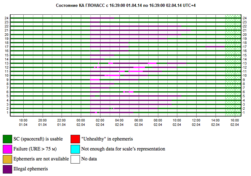
On April 2 at 1:00 a.m. Moscow time, bad ephemeris was uploaded to all satellites (see chart at the bottom of this story).
There are two receivers shown here, from two different manufacturers, both in smartphones. The yellow dots are for a GPS/GLONASS receiver; the blue dots are from the Broadcom 47531 receiver which tracks GPS/GLONASS/QZSS/BeiDou signals simultaneously. The 47531 receiver includes logic to use redundant measurements to check the validity of all measurements. It successfully identified and removed the bad GLONASS ephemeris 100 percent of the time, as can be seen by the continuity and accuracy of the positions.
Here is the satellite outage chart from yesterday’s story. All GLONASS satellites were restored to healthy state after the 11-hour interruption.
Current plot from the Roscosmos GLONASS Information-Analytical Centre. Things are almost back to normal this morning.
Galileo Growth, Constellation Updates, and Jamming
I used to spend quite a lot of time in Munich working on a multi-national, multi-role fighter aircraft program, so returning for this year’s Munich Satellite Navigation Summit stirred some good memories for me.
Held in the opulent Residenz Muenchen March 25-27, the conference always has a special atmosphere that these historic 1385 surroundings convey to the attendees. The former royal palace of Bavarian monarchs, the whole complex has ten courtyards and 130 rooms. The summit was held in the Max-Joseph Hall, which took a little bit of work to find at first, wandering around the huge complex. One wing of the building hosts a theater, and the mainhall is the primary concert venue for the Bavarian Radio Symphony Orchestra. Overall, this is a delightful setting.
Munich is in the Southern German state of Bavaria, and Bavaria has taken a real interest in the promotion and success of Galileo; witness the extensive Bavarian booth at recent European and North American GNSS conferences. Germany has, of course, been one of the principle nations providing significant funding for Galileo from its inception.
Ilse Aigner
So with this backdrop, the summit brings together people involved with GNSS from around the world to report on the current status of GNSS and to relate how their participation in satellite navigation has progressed. And, of course, Europe, Germany, Bavaria and the European GNSS industry, which is now recognized around the world, all take the opportunity to present their capabilities and successes.
The plenary session on the first evening covered GNSS, Earth Observation (EO) and Telecommunications — with the panel headed by Ilse Aigner, Bavarian State Minister of Economic Affairs and Media, Energy and Technology — an extensive mandate, even for a state-certified engineer who used to work for Eurocopter.
Dr. Merith Niehuss, speaking at the opening of the summit. (copyright: Munich Satellite Navigation Summit).
The host of the summit is actually the University of the German Army in Munich, and we received a warm welcome from two leading professors: Dr. Bernd Eissfeller and Dr. Merith Niehuss, the president. The theme of the summit was to move from implementation to utilization, and in typical European form, all parties were looking to shower potential users with funded solutions to problems of which users are not yet aware — so users clearly need government-provided education, pilot projects and funding. Not exactly a North American concept, where we tend to encourage users to buy our innovative stuff by demonstrating how it can save them money or earn them more revenue.
The European Commission, ESA, DLR, European GNSS Agency (GSA), Airbus, OHB, and Telespazio were also represented. The minister did indeed associate with and praise the local area, claimed 1,000 jobs created related to Galileo through an incubation center at Oberpfaffenhofen, and declared Bavarian support for satellite navigation.
Other important things mentioned by the panel at the plenary included an €11B budget for Galileo/EGNOS and Copernicus (EO project) under the Horizon 2020 program, and an intent to declare Early Service for Galileo before the end of this year with two or three dual Galileo satellite launches — the first two FOC (production) SVs should go to the European launch center in Kourou in April in preparation for launch around June. I heard in a corridor that launches may be planned for June, October and December, but an EU spokesman later said that there would only be two launches this year. OHB now has the contract to build 22 FOC Galileo SVs, each with a design life of 14 years, and they are bullish on their ability to deliver on time and budget.
The program continued the following day with constellation updates from GPS, Galileo, Beidou and the UN International Committee on GNSS (ICG) — GLONASS delegates were notably absent. There was much speculation that they declined to attend due to the Crimean situation, and one U.S. delegate even inferred that they were “uninvited.”
Constellation Updates
GPS: It’s estimated that there are ~2B GPS receivers in use, and there may be ~10B by 2020. A return on investment (ROI) analysis is currently underway, but a rough guess is that costs are in the tens of billions, while annual returns are of the order of $60-100B/year. Another IIF satellite (SV) launched last month, bringing the total to five SVs transmitting L1, L2C and L5, with seven more to come, and multiple launches are expected this year. There are 30 operational SVs on orbit, signal performance significantly exceeds the specs, and consistent, dependable performance has been provided for more than 20 years.
Galileo: First fix was achieved March 12, 2013, with four SVs, two (maybe three?) launches of two SVs each planned for 2014, and early operational capability to be declared by end of this year. €7B in funding is provisioned for 2014-2020, with 16-24 operational ground stations, Commercial Service (CS) planned by 2016 (more on this later), and a long-term evolution plan being worked up during this year.
BeiDou: Fourteen SVs are on orbit — five GEO, four MEO and five Inclined Geosynchronous Orbit (IGOS) satellites, providing dual-frequency services. Thirty total SVs are planned, and the intent is to provide open, compatible, interoperable signals with other GNSS free of charge. There was not much other news to report, other than that China intends to invest significantly in BeiDou to keep improving services.
United Nations ICG: Nine nations and European Union = International Committee on GNSS (ICG), with 20 other associate and observer States. Activities include GNSS compatibility/interoperability, GNSS enhancements, information sharing, and reference frames, timing and applications — lots of upcoming meetings and activities.
Regional and Augmentation Updates
WAAS: Phase IV is underway with GEO replenishment begun, introduction of L5 to replace L2, and replacement of obsolete component parts. One hundred GIII receivers were ordered with L1/L2C and L5 capability for delivery by September this year — and have capacity to also add Galileo. GIII receivers have already been fielded in six locations as part of initial integration testing. The Safety computer will also be upgraded starting this year. 3,912 LP/LPV approaches have been approved, of which 3,379 LPVs serve 1,667 airports. GBAS CAT I is progressing with four U.S. airport installations. System design approval began in January this year, and United Airlines has begun equipping over 90 B737/B787 for GPS approach and landing. Alternative Positioning, Navigation and Timing (APNT) investigations are underway (as a backup to GPS) with a hybrid DME-pseudolite configuration currently favored. Stanford University subsequently presented this and other concepts.
EGNOS: A €1.58B budget has been approved, and EGNOS V3 evolution is underway, with L1/L5 and GEO (SES 5 and Astra 5B) replenishment, a requirement to expand East and West and to the North to provide full coverage to all EU States.
About 100 EGNOS LPV approaches are approved — this year, it’s hoped to add 150 more.
QZSS: The operational concept has been proven with the first IGOS SV (Michibiki), so Japan is moving forward quickly to add another three SVs (3xIGOS and 1xGEO) and ultimately would like to have a total of seven SVs in orbit providing QZSS services. L1/L1C/L2C/L5 signals are identical to GPS, and L1s/L5s are augmentation signals, while L6 is proposed to be similar to Galileo E6, providing centimeter-level PPP-type service. QZSS essentially is intended to provide higher elevation satellites to improve urban navigation in dense cities.
IRNSS: Coverage extends 1500 km beyond India. The target is <20-meter accuracy, and signals are in L5 and S band and can be used independently or in dual-frequency combinations. A second IRNSS-1B GEO satellite is scheduled to launch on April 4.
GAGAN: The Indian SBAS was commissioned and certified in February this year with a number of ground stations, redundant uplinks and two on-orbit GSAT 8 and 10 GEOs. Gagan is now qualified to provide RNP0.1 (navigation accuracy to 0.1 miles).
QZSS and Japan’s Space Policy
This session provided some detail on how changes in Japan’s Basic Space Law has lead to efforts to expand the use of space and derive further economic benefits that this provides.
Munich Highlights
A collection of examples of Bavarian GNSS innovations followed in a very interesting session led off by an overview of Business Incubation Centers and their collaboration with government agencies and research centers. Small business start-ups are apparently encouraged to apply during four annual time-slots, and receive two years’ incubation support and cash incentives. This has lead to 81 new ventures and has apparently been the source of the 1,000 new jobs mentioned by the Minister of Economic Affairs. The annual European Satellite Navigation Competition and Galileo Masters competition have also generated a whole bunch of ideas and concepts (8,000), some of which have found support through this incubation process.
Airbus Defence gave a short overview of the testing work it accomplished in supporting the first Galileo fix and has prepared several vehicle test platforms, ready to take the next phase of Galileo testing to the streets in realistic, real-world environments.
DLR provided insights into a number of its activities, namely:
Iono mapping
Signal distortion
Multipath
Jammer mitigation – adaptive antenna and processing
GNSS repeaters – how they can become unintentional jammers
Spoofer and Multipath inbvestigations
Antenna designs
GNSS evolution – Maser and clock combination benefits
Army University of Munich discussed radio science experiments in the Solar System and experiments using Mars Express (above) in polar orbit around Mars and resulting measurements of the moon Phobos. Internal and external outreach efforts with numerous organizations were also mentioned.
IFEN provided more down-to-Earth information on the on-going activities at the GATE ground-based pseudolite range, which has enabled realistic outdoors testing of Galileo receivers, well in advance of signals from orbiting satellites. Recent testing has now been able to include the four operating Galileo SVs on orbit with GATE pseudolite signals. GATE will continue to evolve over the next few years to keep up as more Galileo orbital signals come on-line.
Fraunhofer presented information on its 40-channel GPS/Galileo/GLONASS chip-receiver (above) – claiming 1-meter accuracy, low-cost, robust reliable position solution, small form-factor and low-power. Following PRS test-bed development efforts, Fraunhofer has now received a contract to also deliver 20 pre-operational Galileo PRS receivers for use in initial pilot projects.
GNSS Interference
Vidal Ashkenazi, in his inimitable form, lead a panel discussion on interference, jamming (in particular Personal Privacy Devices, or PPD) and spoofing, and coaxed his panel members to provide a whole bunch of information on what’s being done, mitigation capabilities and potential enforcement. Unlike all the other sessions, Vidal’s panel members didn’t use presentations, but rather responded to wide-ranging questions on the subject from the session chair.
David Turner, representing the U.S. State Department, indicated that the ICG will meet shortly in Geneva hosted by the International Telecommunication Union (ITU) to focus on interference, jamming and mitigation. The recourse that nations have for use of PPDs by their people is the law — jammers are illegal, sale and purchase of them is illegal — however, Internet sales are very difficult to police. So detection and mitigation are required to find and shut them down. Dave’s presentation on the GPS.gov website indicates that the ICG is working on an education program for states to inform about GNSS sensitivity to interference and the threat to critical infrastructure if they are allowed to operate. The ICG also has a task force on detection, reporting and systems development.
ISRO indicated that PPD jammers in India are restricted, but permitted for gatherings such as at churches where personal safety may be an issue. Ground-based detection is needed, as well as stronger legal protection that may well prohibit use of PPDs altogether.
Japan Aerospace Exploration Agency (JAXA) indicated that it is working on “signal proofing” for QZSS.
BeiDou said it is building a monitor network in China that will detect jamming.
There was a general discussion on whether receiver manufacturers should be mandated to make receivers that are resilient to jamming – many thought that there have already been significant advances in that direction by manufacturers. The normal approach would be to develop requirements with industry, agency and user inputs, publish them, and call up the requirements in equipment specifications. In the U.S., the Department of Homeland Security is seeking an approach to detection and location.
Legal Impacts of Personal Privacy Devices (PPDs)
While the audience may have had high hopes that the legal eagles could come up with some magic prevention and prosecution solution, the next session was more of a legal background briefing without any concrete conclusions (quite similar to other discussions I’ve had with some lawyers in the past, actually).
The first briefing was from the European Commission/European Union, who indicated that the EU doesn’t own the frequency rights to Galileo (Oh Oh…). They have to operate through a member state, which gets the rights through the International Telecommunication Union (ITU) and then licenses use to the EU — the bottom line being that EU enforcement of jamming protection laws maybe be difficult, as the legal framework only exists at the national level for each state. The EU is trying to get recognition under another class of ITU membership.
EU regulations were presented that state that GNSS re-transmitters can only be operated legally by governments or government contractors. Or can be used indoors for indoor navigation, but only for emergency services at fixed sites which are pre-approved. Pseudolites can only be operated indoors, and there should be no interference to other systems. Jammers are forbidden and cannot be placed on the market for sale.
Eurocontrol had a lot to say about the impact on aviation navigation infrastructure and receivers on aircraft. Existing ground nav aids have limitations, the worldwide equipment infrastructure is becoming quite old — aviation has generally moved away to GNSS and inertial based navigation and uses ground navaids as backup. There is a conflict between regulating GNSS heavily for aviation and how people want to use it in the commercial world. We may have to consider a trade-off between heavily restricted GNSS operations, and wide open commercial GNSS applications.
David Sobel, from Electronic Frontier Foundation in the U.S., presented the contrary case for individual privacy. His argument is that sale of tracking devices is unregulated and can readily be purchased, so people may presumably use them to track others, thereby infringing their privacy. So why shouldn’t people be able to “defend their privacy” by use of PPDs?
Say an employer insists that a vehicle you are driving have a tracking device so he knows where you are. Isn’t the driver also justified in trying to protect his privacy? Since the police in the U.S. can no longer place tracking equipment on suspect vehicles without a warrant, tracking appears to be down to private individuals or companies, who it would appear, have the legal ability to attach tracking devices under most circumstances. So the argument goes that if people have a legitimate concern about privacy, there should be acceptable provisions to allow them to disrupt tracking.
If there is a service such as road tolling, there is an incentive for people to avoid these costs. So systems should be robust enough to avoid disruption. Enforcement is a problem — should police chase people they suspect have jammers, or should they rather chase criminals or help and protect citizens? Mitigation systems need testing, so to test these systems there has to be jamming transmission — which needs to be controlled and regulated. Restricting the import of bad devices into a country might be desired, but the manufacturing countries don’t tend to want to restrict exports as exports help their economy. Again, the argument seems to be that of personal privacy over potential risks and damages to society.
No solutions, but a healthy discussion of views from a legal perspective.
Precise Point Positioning (PPP)
The group discussing PPP options consisted of the GSA (charged with exploitation of Galileo services), several principle industry service providers of PPP, and the federal agency, which provides PPP-like services in Germany.
The GSA presented its ideas concerning the provision of high-accuracy PPP corrections over the Galileo E6 signal – the so-called Commercial Service (CS). The intent, however, would not be to disrupt the commercial marketplace. Nevertheless, GSA is proposing a public-funded service to be sold to users within a market that is already well served by commercial worldwide service providers who charge users for cm-level PPP service.
And while Trimble made a polite presentation on the many levels of capabilities of its TerraSat services, as did Veripos and to some extent Fugro, it was clear that the commercial providers are not eager to find competition in their market from a government entity. NovAtel also chimed in on this conflict as it will be involved in Veripos/TerraStar, following its acquisition by Hexagon. Fugro appeared to be interested in acquiring rights to distribute CS on behalf of GSA.
The German Federal agency promoted open data, source and standards from the IGS network to which it contributes: IGS is supported by numerous national agencies around the world. Orbit and clock PPP service is available 24/7 from multiple sources. However, the service is offered on a best efforts basis without a service guarantee, and cannot achieve the accuracies or convergence times of commercial services.
I talked subsequently with Michael Ritter, CEO of NovAtel, to learn the background to the Veripos/TerraStar acquisition. It’s clear that providing PPP services means added value to NovAtel when they sell receivers with PPP capability, so they will quickly discontinue offering Omnistar subscriptions and will shortly launch NovAtel Correct, offering Veripos (marine) and TerraStar (land) PPP subscription services. NovAtel is making significant inroads in the agriculture segment, and they see PPP service as an essential element of this and other businesses. The acquisition was worth something on the order of $200 million, so there is a vested interest in making these services pay and discouraging GSA entry into this market. Veripos will continue supplying other GNSS OEM receiver manufacturers — notably Septentrio, who use TerraStar services, now also NovAtel, and potentially another major GNSS manufacturer.
Future of GNSS in User Segment
Chaired by Greg Turetzky of Intel, this session opened the third day of the Summit. The presenters offered their concepts for current and future GNSS equipment and systems.
Stanford University outlined its work with FAA on an alternate PNT system to be used as a back-up to GNSS. It used to be that GNSS systems were designed to overcome space-weather effects and faults in equipment design or manufacture — nowadays, there are “bad guys” out there and we need to “protect, toughen and augment” these systems. Antennas can be built that impart a specific signature to the signals they transmit, and this may aid in finding and prosecuting the bad guys, but the main focus of work is development of a hybrid system using Distance Measuring Equipment (DME) and a pseudolite.
Tests have demonstrated good performance, and these prototype efforts could lead to aviation requirements (MOPS) development by 2018 and deployment by 2020.
Septentrio has been involved in Galileo since it began and was the first company with Galileo receivers. Nowadays, they have receivers fielded in multiple commercial applications, including machine control, maritime, aviation, automation, and measurement, delivering accuracies from a meter down to a centimeter. They will add E6 to their AsteRx family of multiple-channel, multi-frequency, multi-constellation receivers, and have developed a number of hardware and software mitigation techniques to combat jamming, interference and multipath, and to integrate receivers with inertial units for aiding.
Furuno is interested in resilient PNT for marine applications, and has examined the use of eLoran as an alternative to GPS, but has moved towards a system of radar beacons that detect radar pulses from passing ships and transmit their positions, enabling position determination. In tests, accuracies of around 2 meters have been obtained with two beacons.
Quascom’s approach is to add firewalls inside receivers, which toughen the processing and prevent distortion of position information. Quascom believes this will be necessary until authentication can be added into the GNSS system itself, so that any data received is validated and is known to be good.
Chris Rizos from the University of New South Wales, Australia, drew attention to the “holes” that exist in GNSS, and reviewed a number of possible “Band-Aid” fixes, such as Wi-Fi especially for indoor location. However, his solution seems to be to establish terrestrial networks transmitting GNSS-like signals.
Eurocontrol indicated that aircraft currently use inertial and DME extensively as a back-up to GNSS navigation. By 2030, there will be multiple constellations, and dual-frequency use should become commonplace in aviation, so GNSS navigation should be much more robust. Aircraft approaches are required to be in conformance with Required Navigation Performance (RNP), so would it be possible to develop RNP procedures for DME and inertial to be used as back-up during approaches in the event GNSS is disrupted?
To conclude the session, Airbus provided a “starter course” overview on inertial systems – how they work, the range of different types available, what they can achieve, costs, strengths and weaknesses and integration with GNSS.
The summit continued with subsequent sessions on:
Space technologies and users
GNSS monitoring of Earth and disaster management
Copernicus – Earth Observation
GNSS Education
Unfortunately, my deadline didn’t allow me to attend these equally interesting presentations.
There is also a manufacturers’ exhibit area at the summit that just fits into a couple of corridors near the main hall – around 20 booths. I talked with several of the manufacturers, including Spirent who has launched its latest GSS9000 multi-frequency-constellation simulator, with a four-fold increase in system iteration rate over the previous model. Exhibitors appeared to be pleased to be at the summit and by the level of interest shown by the attendees.
So, as this year’s Munich Summit concludes, where does this leave us? We’ve learned some new things about several GNSS topics and heard some interesting new concepts. Europe appears to be now focused on users and applications, to ensure there is market growth and use of Galileo. What stands out for me is the contrast between how European governments go about GNSS and how North America and the commercial world does the same thing without as much direct influence. This is nothing new, of course, it’s just the European way…
By Oliver Montenbruck, Richard B. Langley, and Peter Steigenberger
Over the past several years, some users of the GPS navigation system have already benefitted from the addition of various new signals in addition to the legacy C/A- and P(Y)-code. With the introduction of the Block IIR-M satellites in 2005, a new civil signal (L2C) was transmitted on the L2 frequency, and a new signal on a new frequency (L5) was introduced as a standard signal with the Block IIF satellites beginning in 2010. These new signals provide direct access to dual-frequency observations and thus enable improved ionospheric corrections for civil, including aeronautical, users. In addition, a new Civil Navigation (CNAV) broadcast message has been defined in the GPS Interface Specifications (IS-GPS-200 and IS-GPS-705).
This message will be transmitted jointly on the L2C and L5 signals and provides a variety of useful new parameters. Compared to the legacy L1 C/A-code navigation message, the CNAV message also offers an increased flexibility concerning the type, sequence, and repeat rate of specific messages.
CNAV messages have already been broadcast over the past two years by the Michibiki (QZS-1) satellite of the Japanese Quasi-Zenith Satellite System (QZSS), which shares many aspects of the GPS signal design. In contrast to this, Block IIR-M and IIF GPS satellites have only transmitted dummy messages so far and a fully operational CNAV transmission is only foreseen once the ongoing modernization of the GPS control segment has been completed.
Triggered by various interest groups, the Global Positioning Systems Directorate has just conducted a first test campaign with live CNAV transmissions on L2C and L5 over the two-week period from June 15 to 29 (see Global Positioning System Modernized Civil Navigation (CNAV) Live-Sky Broadcast Test Plan.) It served as a first opportunity for end users and receiver manufacturers to test the decoding and use of the new messages under a wide range of different configurations.
CNAV messages have a common length of 300 data bits and are identified by a message type number that signifies their contents. The messages presently defined for GPS are summarized in Table 1. For QZSS, complementary messages have been established, which enable, among other features, a rebroadcast of GPS-specific data to QZSS users.
Table 1. Summary of CNAV message types transmitted by space vehicles (SVs). Messages marked by an asterisk were transmitted during the recent CNAV test campaign.
Message
Type
CNAV Message Title
Function/Purpose
0*
Default
Default message (transmitted when no message data is available)
10*
Ephemeris 1
SV position parameters for the transmitting SV
11*
Ephemeris 2
SV position parameters for the transmitting SV
12*
ReducedAlmanac
Reduced almanac data packets for seven SVs
13
Clock Differential Correction
SV clock differential correction parameters
14
Ephemeris Differential Correction
SV ephemeris differential correction parameters
15*
Text
Text (29 eight-bit ASCII characters)
30*
Clock, Iono & Group Delay
SV clock correction parameters, ionospheric and group delay correction parameters (inter-signal correction parameters)
31
Clock & Reduced Almanac
SV clock correction parameters, reduced almanac data packets for four SVs
Other than the legacy L1 navigation message, which adheres to a fixed order of subframes, the sequence of CNAV messages can be varied widely to provide users with an optimized set of low latency information and parameters that change infrequently. As a baseline, the two ephemeris message types 10 and 11 are combined with any of the clock-and-auxiliary data messages (types 30 through 37) to provide users with the orbit and clock data of the received satellites. With a transmission duration of 12 seconds per CNAV message on L2C, a minimum of 36 seconds is required to transfer this information to the user if no other messages are transmitted. On L5, which operates at twice the data rate, a new frame is transmitted once every 6 seconds yielding a minimum of 18 seconds for the broadcast of ephemeris and clock data.
The recent test campaign started at 18:00 GPS Time on Saturday, June 15, 2013, with the transmission of message types 10, 11, 15, and 30 on a first space vehicle (PRN24) and included PRN12 from 18:42 onwards. Other space vehicles were sequentially phased in until all active IIR-M and IIF satellites (except for the recently launched IIF-4 satellite) transmitted CNAV on the supported signals. When the test ended exactly two weeks later (June 29, 18:00 GPST), all participating satellites were transmitting a complex master frame of 15 x 4 = 60 individual messages, which was repeated once every 12 minutes (on L2C). Each minor frame comprised the two ephemeris messages and at least one clock-data message (see Table 2).
Table 2. Sequence of message types in a CNAV master frame.
Message Types
10
11
15
30
10
11
32
33
10
11
12
35
10
11
12
30
10
11
12
33
10
11
12
35
10
11
12
30
10
11
32
33
10
11
15
35
10
11
32
30
10
11
12
33
10
11
12
35
10
11
12
30
10
11
12
33
10
11
12
35
Other messages included a reduced almanac (message type 12) and a text message (message type 15) with dummy content (“THIS IS A GPS TEST MESSAGE.”)
The CNAV data were recorded by selected multi-GNSS monitoring stations of the German Aerospace Establishment (Deutsches Zentrum für Luft- und Raumfahrt or DLR) and the University of New Brunswick (UNB), which were specifically configured to record raw GPS navigation frames in addition to the normal observation data. The stations are located at Singapore (SIN0); Sydney, Australia (UNX2); Maui, U.S.A. (MAO0); and Hartebeesthoek, South Africa (HRAG); as well as Fredericton, Canada (UNB) and are equipped with either Javad Delta-G2/G3TH or NovAtel OEM6 receivers. Following initial validation, the raw and decoded data from the CNAV test will be made available to interested users through the Multi-GNSS Experiment (MGEX) of the International GNSS Service (see http:/igs.org/mgex) to facilitate the development of user software and suitable data formats (such as an extended RINEX navigation message format).
The CNAV orbit and clock data were updated once every two hours and offer a slightly higher bit resolution than their legacy counterparts. However, the accuracy of the ephemeris data has not yet been evaluated nor compared to that of the L1 C/A-code navigation data.
As indicated above, the CNAV data can also provide a particularly compact form of almanac data known as the reduced almanac. It does not offer clock information (that is not normally required for a signal search) and assumes a circular orbit, which reduces the overall accuracy. Still, it can be transmitted (and repeated) in a much shorter time interval than the legacy almanac, which requires a total of 12.5 minutes. Each reduced almanac message (message type 12) provides orbit information for a total of seven satellites and it takes a set of five such messages to convey information for a complete constellation. For the master frame layout described above, the full constellation reduced almanac is repeated twice within 12 minutes on L2C (and half this time on L5).
Novel types of CNAV data not covered by the legacy navigation message include the differential code biases (also known as inter-system corrections or ISCs), which are required for pseudorange-based positioning with signals other than the legacy P(Y)-code (in addition to the established Timing Group Delay parameter or TGD). An overview of TGD and ISC values broadcast by the various satellites participating in the CNAV test is given in Table 3.
Table 3. Differential code biases (in nanoseconds) of GPS Block IIR-M and IIF satellites broadcast during the test campaign as part of the message type 30 CNAV messages.
SV Type
SVN
PRN
TGO
ISC L1CA
ISC L2C
ISC L5I5
ISC L5Q5
IIR-M
48
07
-10.71
-0.84
6.52
IIR-M
50
05
-10.24
-0.32
5.41
IIR-M
52
31
-13.04
-0.55
7.36
IIR-M
53
17
-10.24
-0.84
6.17
IIR-M
55
15
-10.24
-0.47
5.62
IIR-M
57
29
-9.31
-0.76
5.06
IIR-M
58
12
-12.11
-0.76
6.64
IIF
62
25
5.59
-2.07
-5.24
-0.38
-0.87
IIF
63
01
8.38
-2.30
-7.57
0.38
2.15
IIF
65
24
2.79
-0.26
-2.27
2.27
3.70
Another important achievement is the provision of Earth orientation parameters (EOP) in message 32, which provides GPS users with access to the celestial reference frame. EOPs were transmitted during the second test week and updated on a daily basis (see Table 4). Knowledge of these parameters is of particular interest for GPS-based orbit determination and navigation of spacecraft (in low Earth orbit), which is preferably referred to an inertial rather than an Earth-fixed coordinate system.
Table 4. Daily Earth orientation parameters from the CNAV test campaign (pole coordinates and dUT1 (UT1-UTC) time differences and derivatives).
Epoch (GPST)
x_p
(arcseconds)
x_p_dot
(arcseconds per day)
y_p
(arcseconds)
y_p_dot
(arcseconds per day)
dUT1
(seconds)
dUT1_dot
(seconds per day)
June 22, 0:00
0.13517
0.00104
0.39657
-0.00054
0.06341
-0.00046
June 23, 0:00
0.13621
0.00102
0.39604
-0.00056
0.06295
-0.00049
June 24, 0:00
0.13740
0.00101
0.39535
-0.00058
0.06231
-0.00053
June 25, 0:00
0.13815
0.00099
0.39487
-0.00060
0.06164
-0.00063
June 26, 0:00
0.13846
0.00096
0.39443
-0.00062
0.06078
-0.00067
June 27, 0:00
0.13885
0.00094
0.39381
-0.00064
0.06004
-0.00067
June 28, 0:00
0.13947
0.00093
0.39310
-0.00066
0.05909
-0.00063
June 29, 0:00
0.13987
0.00090
0.39246
-0.00068
0.05842
-0.00053
Overall, CNAV offers exciting prospects for improved GPS utilization and users may look forward to the next test campaigns, which will tentatively be conducted once every six months.
As a side note, it should be mentioned that individual satellites could be observed to transmit various types of non-standard CNAV messages as well as CNAV messages with improper data (such as an invalid week count) after the end of the main test campaign. Various receivers in the MGEX network, which were processing the received CNAV messages internally and which put full confidence in their proper contents, were mislead by such information. During the actual test campaign, all data appeared fully valid and no problems were reported by the stations.
OLIVER MONTENBRUCK is the head of the GNSS Technology and Navigation Group at DLR’s German Space Operations Center in Oberpfaffenhofen, Germany.
RICHARD B. LANGLEY is a professor in the Department of Geodesy and Geomatics Engineering at the University of New Brunswick, Fredericton, New Brunswick, Canada.
PETER STEIGENBERGER is a staff member in the Institut für Astronomische und Physikalische Geodäsie of the Technische Universität München (TUM) in Munich, Germany.
The status of world GNSS, and augmentation systems in the Pacific region, highlighted the policy session of the Institute of Navigtion Pacific PNT Conference being held this week in Honolulu, Hawaii. Here are a few highlights:
BeiDou. Construction of the second phase of BeiDou has been completed; further launches for the third phase – constellation completion – are on hold until tests of the existing 14-satellite constellation are complete, according to Xiancheng Ding, Senior Advisor, China Satellite Navigation Office. As of December 27, 2012, BeiDou achieved full operational capability for most of the Asia-Pacific region. The full constellation is now expected to be completed by 2020.
Other accomplishments include releasing the BeiDou Interface Control Document and manufacture of BeiDou chips for end-user applications. By the end of June, some manufacturers will release BeiDou chips in China, Ding said.
Also in December, BeiDou introduced a new logo (at right).
Yuanxi Yang (China National Administration of GNSS and Applications) presented statistics showing that BeiDou+GPS provides greater accuracy than GPS alone. For instance, the RMS of BeiDou+GPS kinematic positioning by using differential carrier phase is about 20 percent better than that of GPS alone, Yang said.
By itself, existing BeiDou constellation system accuracy is better than 10 meters, timing better than 20 nanoseconds, and velocity accuracy is better than 0.2 meters/second.
In all, BeiDou is composed of 14 satellites: five GEO, five IGSO, and four MEO. The full constellation (by 2020) will consist of 35 satellites: 5 GEO and 30 non-GEO (a mixture of MEO and IGSO satellites).
GPS. Keynote speaker David A. Turner (U.S. Department of State) shared his time with surprise GLONASS speaker Sergey Revnivykh (International Committee on GNSS, ICG). In his GNSS Policy and Program Update, Turner provided the dates by which three new civil signals will be on 24 GPS satellites.
The L2C signal is a developmental signal broadcasting from 10 GPS Satellites. It began launching in 2005 with GPS Block IIR(M) satellites, and is expected to be available on 24 satellites around 2018.
The L5 signal is a developmental signal broadcasting from three GPS satellites. It began launching in 2010 with Block IIF satellites, and is expected to be available on 24 GPS satellites around 2021.
The L1C signal begins launching in 2015 with GPS III; available on 24 GPS satellites around 2026.
“We have an increasing number of signals, increasing capability, and increasing level of service as we continue to evolve the constellation,” Turner said.
GLONASS. The next GLONASS satellite will be launched this Friday, April 26, Revnivykh said. This will be a GLONASS-M satellite, number 47. The first launch of a new generation GLONASS K satellite is scheduled for 2015.
Revnivykh stressed GLONASS’ role as a global utility. “We consider international cooperation is essential for all GNSS, and we consider GLONASS an essential part of the international multi-GNSS system,” he said. He stressed the importance of compatibility and interoperability as key to this policy.
In 2012, GLONASS performed with an average accuracy better than formally required, he said. GLONASS is in worldwide use, and positioning has improved by a factor of 10, from 35 meters to about 3 meters since the first satellites were launched. Using both GPS + GLONASS provides 1.5 times better high-precision measurements, Revnivykh said.
The new GLONASS program for 2020 for GLONASS sustainment, development, and use includes GLONASS M, K1, and K2 satellites; the positioning accuracy objective is to go from the current 2.8 meters to 0.6 meters.
Aviation. Chris Hegarty (MITRE) presented an FAA Navigation Programs Overview on behalf of the scheduled speaker Deborah Lawrence (FAA) who was unable to attend. He noted that United Airlines has begun GBAS operations in Houston.
In answer to a funding question, he said, “The sequestration is not expected to have a positive effect on schedule, but the presented timeline for APNT is the FAA’s current best estimate. Congress has some tough decisions before them, and I wouldn’t want to speculate on potential schedule impacts. In the words of Yogi Berra, predicting is hard, especially when it involves the future.”
Korean SBAS. Changdon Kee (Seoul National University) shared plans for a Korean SBAS. In South Korea, LPV availability is 49.4% compared to 90.6% in Japan. “Korea needs its own system,” Kee said.
Phase 3 of the SBAS development could start by the end of September, depending on funding. It will include open service multifunctional GEO satellites interoperable with other SBASs. A pseudolite demonstration system will be completed in 2014, clearing the way for the beginning of Phase 3.
In all, the system will include five reference stations, two master stations, two ground uplink stations, and two GEO satellites (the main GEO by 2018 and a backup by 2020).
The Korean SBAS open service system will provide GPS L1 augmentation, begin operation in 2020, and support aviation, land and maritime users. A test operation system will provide GPS L1 and L5 augmentation. The system is expected to be fully operational by 2021, with service available throughout Asia.
Japan’s QZSS. Hiroyuki Noda (Office of National Space Policy, Japan) said three moresatellites for this augmentation system will be launched by the end of the decade, with the service beginning in 2018. In September 2012, the Japan cabinet made the commitment to accelerate development of the system. The first satellite, launched in 2010 (QZS-1, aka Michibiki) is performing as expected.
QZSS is expected to improve positioning availability from 90% to 99.8% in Japan. QZSS will not only improve positioning in the Asia-Pacific region, but is expected to improve the capacity to respond to natural disasters, Noda said.
The Japanese government has ordered three navigation satellites from Mitsubishi Electric Corp. to expand the Quasi-Zenith Satellite System (QZSS), reports Spaceflight Now. QZSS augments GPS navigation signals for users in the Asia-Pacific region.
NEC Corporation has also been awarded a contract, for the Ground Control Segment.
Japan’s Cabinet Office announced the QZSS expansion on March 29, approving a $526 million contract with Mitsubishi Electric for the construction of three satellites for launch before the end of 2017. Two of the spacecraft will be placed in inclined orbits, and one satellite will operate in geostationary orbit over the equator.
Michibiki, the website version.
NEC Corp. will operate QZSS for 15 years under a $1.2 billion contract that covers the design, verification and maintenance of the QZSS ground system.
Furuno Electric Co., Ltd., has announced that new multi-GNSS receiver chips eRideOPUS 6 and eRideOPUS 7 will be available in August. The new receiver chips are multi-GNSS compliant single-chip LSIs, capable of concurrently receiving signals from multiple satellites in GNSS systems and satellite-based augmentation systems, as well as Japan’s Quasi-Zenith Satellite System. Both chips receive signals from GPS and Galileo; the eRideOPUS 7 also receives GLONASS signals.
The ability of concurrently receiving GNSS/GNSS augmentation signals from multiple satellites from different satellite services means that the receivers have more probability of acquiring a greater number of satellites at any single time. Subsequently, position stability as well as accuracy will be greatly improved, minimizing the chance of a position lost. Also, the receiver chips incorporate an enhanced level of noise rejection capability, implementing the anti-jamming function as well as the improvement of multipath mitigation.
Time-to-first-fix capability of the existing eRideOPUS 5 (no more than 1 second when hot started) is retained in these new receiver chips with a combination of A-GPS compatibility and self-ephemeris extraction. Moreover, the position update rate of the new receiver chips is greatly improved, achieving a 10-Hz update (every 0.1 second), which is twice as fast as the capability achieved by eRideOPUS 5.
The new receiver chips are capable of dead-reckoning navigation, using a gyro sensor and vehicle speed pulse signals, a gyro sensor and an acceleration sensor, and wheel tick data taken from a CAN-Bus network, achieving high positioning accuracy even in locations where satellite signal reception is not available, such as inside tunnels.
In May 2013, Furuno is planning to start the delivery of evaluation kits for the receiver chips so that third-party manufacturers can evaluate the feasibility of incorporating the receiver chips into their products, and in August 2013, the new compact GNSS receiver module GN-86/GN-87 as well as
dead-reckoning-capable GV-86/GV-87, using these new receiver chips, will be made available for automotive navigation systems as well as eCall systems.
u-blox, the Swiss positioning and wireless module and chip company, has announced its latest multi-GNSS receiver modules MAX-7, NEO-7 and LEA-7 in u-blox’s form factors. They support all satellite positioning systems in operation today: GPS, GLONASS, QZSS and SBAS. The modules target telematics applications such as asset and fleet management as well as portable tracking devices.
“Each MAX-7, NEO-7 and LEA-7 variant delivers fast, accurate and reliable GLONASS and GPS positioning with the industry’s lowest power consumption.” said Daniel Ammann, executive VP of positioning product development at u-blox. “Both GPS AND GLONASS modes perform even better than combined GPS/GLONASS solutions available on the market today.”
All u-blox 7 generation modules are pin-to-pin compatible with previous u-blox 6 and u-blox 5 families allowing easy upgrade from existing designs. Each module is available in cost-effective variants (such as MAX-7C; NEO-7M) as well as performance optimized variants (MAX-7Q, MAX-7W, NEO-7N, LEA-7N).
u-blox 7 modules use GPS/GNSS chips qualified according to AEC-Q100 and are manufactured at ISO/TS 16949 certified sites. Each module is intensively inspected and tested during production. The modules are fully qualified according to ISO 16750 – “Environmental conditions and electrical testing for electrical and electronic equipment for road vehicles” to provide high durability and reliability.
All modules comply with green/halogen free standards.
First variants available will be NEO-7N (November 2012) and MAX-7C (December 2012).