The International Symposium on Satellite Navigation 2023: Advances, Opportunities and Challenges (ISSN 2023) will take place Nov. 20-22 in Jiaozuo, Henan, China.
ISSN 2023 will provide a platform for GNSS scientists and engineers to communicate and exchange theories, methods, technologies, applications and future challenges.
The event is open to all scientists who may have the latest results and developments in BeiDou (BDS) and GNSS+, including constellations, signals, orbits, receiver design and multi-sensor fusion, as well as positioning, navigation and timing theory, algorithms, models and applications in engineering and Earth science.
Manuscripts on new advances in multi-GNSS and other regional systems, compatibility, interoperability and new applications are also welcome.
ISSN 2023 is jointly sponsored by Henan Polytechnic University and the Editorial Office of Satellite Navigation. Main topics and sessions include:
The full GNSS User Technology Report 2020 is available for download. (Cover: GSA)
News from the European GNSS Agency
The European GNSS Agency (GSA) has released its latest GNSS User Technology Report, providing a comprehensive analysis of GNSS trends and developments.
With four GNSS available and more than 100 satellites in operation broadcasting multiple frequencies, the GNSS industry is shifting towards the wide adoption of multifrequency receivers across market segments to meet the diverging user needs of emerging applications.
The report includes contributions from leading GNSS receiver, chipset manufacturers and service providers, and serves as a valuable tool to support planning and decision-making with regards to developing, purchasing and using GNSS technology.
Published biennially since 2016, the User Technology Report has become a point of reference for the GNSS industry, research and policy-makers.
Rapid Evolution
‘’The GNSS industry is evolving at a rapid pace and is shaped by the dynamics of emerging applications and user needs as well as the upgrade of existing and new GNSS and Satellite Based Augmentation Systems (SBAS),” said Rodrigo da Costa, GSA executive director. “The industry has understood the potential of Galileo’s unique features.”
The third edition of the report begins with a chapter devoted to technology trends common to all segments: receiver design, position processing and signal processing. It also discusses protection measures against GNSS jamming and spoofing, such as authentication, including what 5G and other technologies and sensors can do, in combination with GNSS.
With multi-constellation now being the norm, the industry is moving towards the wide adoption of multi-frequency receivers even for usually power- and cost-constrained consumer solutions. The Galileo E5 is becoming the preferred frequency with about 20% of all receiver models in the market already using it.
The report is built around four macro segments defined on the basis of commonalities from a technology point of view:
high volume
safety- and liability-critical
high-accuracy
timing devices and solutions (a new-entry in this edition)
Each chapter starts with the macrosegment characteristics and receiver capabilities, depicts the industry landscape and typical receiver form factor, it then delves into the key current and future drivers and trends, and finishes with the added value of the EGNSS, Galileo and EGNOS, for the macrosegment at stake.
Space Data for Europe
This year editor’s special “Space Data for Europe” sheds light on the role that Copernicus and Galileo play within the European Space Programme in the data management and use, now and in the future. It also provides a vision of major transformations underway within our society and our economy and the benefits expected from this digital transformation, paving the way towards the European Data Strategy and Green Deal.
“Today, Galileo and EGNOS already provide increased capabilities which are being used across a broad range of applications, and are already igniting the next generation of location-based applications. In the future, new services — the Galileo High Accuracy Service (HAS), Galileo Open Service Navigation Message Authentication (OS-NMA) and Commercial Augmentation Service (CAS) — will raise the accuracy and reliability bar even higher, and dramatically enhance positioning, navigation and timing solutions for businesses and citizens.
By bringing insight and understanding into the evolutions of GNSS technology, we are creating opportunities for innovation,” concluded da Costa.
Two workshops convened in recent weeks in the U.S. and Canadian capitals, respectively, sought to bring into focus looming threats to the nations’ positioning, navigation and timing capabilities and critical infrastructures. Some of the threats are pervasive — jamming and spoofing — and formed the general topic of the Canadian workshop. Some threats are specific — powerful terrestrial transmitters overwhelming GPS/GNSS receivers — and occasioned the U.S. gathering.
Canada. In a first for Canada, the October 21 GNSS Vulnerabilities Innovation Policy (VIP) Workshop brought together 19 federal government departments as well as provincial and municipal agencies and private sector companies. U.S. State Dept. and Homeland Security gave presentations, as did the European Space Agency, Bell Canada, NovAtel and Spirent Communications.
Integrity challenge for automotive positioning, presented by NovAtel
The workshop was sponsored by the the Federal Global Navigation Satellite Systems Coordination Board (FGCB), a government board with representations from various government departments and agencies. The GNSS Coordination Office (which organized the workshop) is hosted at Canada’s Ministry of Innovation, Science and Economic Development and sponsored by the FGCB members.
Presentations covered such topics as Demonstration of the Geolocation of GPS Jammers, GNSS & the Telecom Sector, Detecting and Protecting Against GPS Cyberthreats, and Safety Critical, High Precision, GNSS Positioning for Autonomous Vehicles.
United States. The U.S. Department of Transportation (DOT) hosted its fifth workshop on the GPS Adjacent-Band Compatibility Assessment effort on October 14. This lengthy, thorny and occasionally acrimonious process started out benignly enough in 2010 with the statement, “Demand for commercial spectrum to support broadband wireless communications has led the government to consider repurposing various radio frequencies, including the satellite communications bands next to GPS.”
The workshop discussed the results from testing of various categories of GPS/GNSS receivers including aviation (non-certified), cellular, general location/navigation, high precision and networks, timing, and space-based receivers. The workshop also included a discussion on the development of use-case scenarios for these categories — which is where the going got heavy and differences of opinion truly emerged.
The furor stems from a renewed effort by Ligado, formerly known as LightSquared and now re-emergent from a 2-year bankruptcy process, to convert relatively inexpensive satellite-to-earth spectrum into very valuable terrestrial spectrum. The company stands to gain billions of dollars and secured rights from the process.
Members of the DoT team presented the first results from the GPS Adjacent-Band Compatibility (ABC) Assessment, an effort to determine the power limits by frequency, or interference tolerance masks (ITM), needed to protect both existing and future GPS receivers. Test results indicated a need to limit interfering signals at different levels depending on the type of receiver being used. 80 receivers in six categories were tested: cellular, general location/navigation, general aviation, timing, high precision and space receivers. Certified and military receivers are undergoing separate tests.
The tests of current receivers took place April 25–29 at White Sands Missile Range, New Mexico, using a 100 x 70 x 40 anechoic chamber. The signals used in the test included GPS L1 C/A-code, GPS L1 P-code, GPS L1C, GPS L1 M-code, GPS L2 P-code, SBAS L1, GLONASS L1 C, GLONASS L1 P, BeiDou B1I and Galileo E1 B/C. Tests were conducted within 100 megahertz on either side of the GPS L1 center frequency of 1575.42 using a 10-megahertz LTE signal and a narrow bandwidth 1-megahertz bandpass white noise signal.
The tests were conducted for GPS and GNSS receivers processing signals in the 1559–1610 MHz Radionavigation Satellite Service (RNSS) frequency band, as well as receivers that process Mobile Satellite Service (MSS) signals in the 1525–1559 MHz band to receive differential GNSS corrections.
The tests determined the power levels at which each device experienced a one-decibel degradation in the carrier-to-noise density ratio (CNR) at a particular frequency. The DoT team graphed results for each device. The recommended power limits were the lowest in frequencies closest to the GPS bands.
The receivers most affected by the test transmissions were identified as high-precision receivers. They experienced interference at power levels as low as –90 to –95dBm at around 1550 MHz and –90 dBm at roughly 1610 MHz.
The strictest limit for both the general aviation, general navigation/location, and timing receivers was a little below –80 dBm at about 1550 MHz, while space-based receivers were equally sensitive on both sides of the RNSS band with the toughest limit being about –85 dBm.
FAA. The Federal Aviation Administration (FAA) has authority to set power and out-of-band emissions limits to meet aviation safety standards, and it had been thought that these limits might address interference with other types of receivers as well. But the test results showed that “protecting the FAA-certified mask does not necessarily protect the rest of the receiver categories,” according to Hadi Wassaf, technical lead for GPS interference analysis at DoT’s Volpe Center.
Use Cases. Ligado has proposed that position error as experienced by the user is a better guide to interference levels than degradation in the carrier-to-noise density ratio. The GPS community generally opposes this approach. The next step is the development of use cases. According to the test plan, use cases define the regions of operations for a receiver, and they identify applications that “that are vital to economic, public safety, scientific, and/or national security needs and any other factors supporting why this particular receiver model is important to be tested (e.g., quantity in use, economic impact, etc.).”
Advances in micro-electro-mechanical systems (MEMS) sensor technology include temperature-sensing MEMS oscillators (TSMO). Pairing a TSMO with a GNSS receiver, the authors successfully performed carrier-phase positioning and obtained accuracies better than typically required for automotive applications. MEMS oscillators can present space and cost advantages in integrated circuit assembly. By Bernhard M. Aumayer and Mark G. Petovello
MEMS oscillators have found their way into the electronics industry and are on their way to enter a multi-billion consumer devices market, which is currently dominated by crystal-based oscillators. One technology review concluded that MEMS oscillators fill the gap between high-performance quartz and low-performance LC (inductor+capacitor) oscillators while allowing for better system and package integration.
Nevertheless, due to stringent requirements on frequency accuracy and phase noise, MEMS oscillators have not yet been integrated in GNSS receivers.
In earlier research, we demonstrated the feasibility of using a temperature-sensing MEMS oscillator (TSMO) in a software receiver, operated over the full industrial temperature range (–40° to +85° C) for pseudorange (code) positioning. However, high-accuracy carrier-phase positioning techniques require uninterrupted carrier-phase tracking, producing more challenging requirements for the receiver’s oscillator.
Here, we extend that research to demonstrate the feasibility of using a TSMO for carrier-phase positioning.
Background
The MEMS resonator used here has an approximately 150 ppm frequency drift over the temperature range of –40° to +85° C, which is about three to five times greater compared to a standard crystal. The integrated temperature sensor provides very good thermal coupling with the resonator, enabling accurate frequency estimation once the frequency versus temperature function (FT polynomial) is estimated.
This FT polynomial can be estimated by periodically measuring the frequency and temperature at different temperatures, and fitting the FT polynomial to the measurements. After this calibration stage, the oscillator frequency error can be estimated using the temperature measurement and the polynomial only. This frequency error can aid the GNSS receiver for acquiring and tracking signals.
As the temperature measurements are affected by noise — which is also amplified by the FT polynomial, producing frequency noise in the receiver — the temperature measurements can be filtered accordingly to reduce noise.
Methodology
Temperature compensation of the oscillator frequency can be beneficial in scenarios with fast changes in temperature (and therefore fast changes in frequency) or when operating the oscillator at extreme temperatures, where temperature sensitivity is more pronounced. The TSMO implements an onchip integrated temperature sensor in close proximity to the resonator and provides an accurate estimate of its temperature. We first examine more complex and non-real-time capable filters to assess performance improvement and limits of bandwidth reduction.
For the second part of this research, where the TSMO based GNSS receiver’s measurements are used for RTK positioning, none of the conditions requiring temperature compensation (fast changes or extreme temperatures) are met, and therefore temperature compensation was not applied.
Temperature Measurements Filtering. When temperature compensation is applied, filtering of the chip-integrated temperature sensor measurements is performed to reduce measurement noise introduced by the temperature measurement circuit. As the signal frequency and phase from the satellite can — under negligible ionospheric scintillation conditions — be assumed significantly more accurate and stable than the local oscillator’s carrier replica, common errors in the received signals’ carrier frequencies can predominantly be accredited to the local oscillator.
Therefore, under the condition of a defined tracking loop, estimated frequency accuracy and phase tracking stability are suitable measures of the local oscillator’s short-term frequency and phase stability, as well as the influence of the temperature compensation.
The temperature compensation method is being digitally applied to the digitized IF signal as a first stage in the software receiver (Figure 1). For generating this signal, a filtered version of the raw temperature measurements is generated and a function (temperature compensation or FT polynomial) to convert those temperature measurements to local oscillator frequency estimates is applied.
Figure 1. Temperature compensation and signal processing structure.
The digitized IF samples of the received signal as well as the frequency estimates from the temperature measurements are then processed by the GSNRx software GNSS receiver developed at the University of Calgary. Satellite-specific phase-lock indicators (PLI) as well as the receiver’s clock-drift estimates are extracted and analyzed, and compared to the results from other filter implementations.
The temperature filters are designed as a combination of variable length finite impulse response (FIR) filters and 1-tap inifinite impulse response (IIR) filters, as this design yields a reasonable trade-off between high stop-band attenuation, small group delay, low complexity and high filter stability. Although feasible in hardware implementations, multi-rate filtering approaches were not investigated.
The filters used are summarized in Table 1, where filters #1 and #2 were used in our previous research. In the table, BC denotes a box-car FIR filter implementation, and BW refers to an approximated brick-wall filter (truncated sinc in time domain). Although the order of the filter is higher, all feedback coefficients (an) other than the first a1 are zero for stability reasons. The stated bandwidth is the 3 dB bandwidth of the filter, (fwd/bwd) indicates forward and backward filtering, and GDC indicates group delay compensation.
Table 1. Filter implementations for temperature measurements.
Carrier-phase positioning. It is well known that carrier-phase measurements can deliver much higher accuracy positions than pseudorange measurements. The challenge for MEMS oscillators is to mitigate the phase noise of the resonator, and any noise resulting from temperature compensation, to allow continuous phase tracking. Failure to do this will result in more cycle slips, which in turn will limit the benefits of using carrier-phase measurements (since the navigation filter will have to more frequently re-estimate the carrier-phase ambiguities).
Testing
The static data set collected in our earlier research was reused for this work. The data was collected from a static rooftop antenna, while the TSMO was placed inside a temperature chamber, which was performing a temperature cycle from +85° to –30° C and back up to +60° C. The temperature compensation polynomial (Figure 1) was fit using the clock drift estimate from running the software receiver with the same data set without any temperature compensation. The temperature filters in Table 1 were then applied to the raw temperature measurements, and processed with the same software receiver as in our earlier work, allowing for direct comparison of the results.
Carrier-phase positioning. To mitigate effects from orbit and atmospheric errors, first a zero-baseline test was carried out on a rooftop antenna on the CCIT building at the University of Calgary. Two identical IF sampling front-ends with a sampling rate of 10 MHz were used for each of the tests, one utilizing a built-in TCXO and the other using the external MEMS oscillator clock signal. A commercial GNSS receiver was used as a static base for this setup. The TSMO and TCXO based front-ends were used as a rover, all connected to the same antenna. For all tests, only GPS L1 C/A signals were used by the devices under test.
Second, a short-baseline test utilizing two antennas about 2.5 m apart was carried out, with the same equipment. For reference, surveyed coordinates of the antennas’ base mounts were used. For these two tests, the front-ends and oscillators were at constant temperature (to within variation of room temperature) on a desk.
Third, two road tests in a car driving around Springbank airport close to Calgary were performed. One test involved smooth driving only, and the second test was performed by rough driving over uneven roads so that higher accelerations on the oscillators were provoked. To allow a performance comparison between the TCXO and TSMO based receivers, the two front-ends were used as rover receivers at the same time and were connected to the same geodetic-grade antenna mounted on the vehicle’s roof.
Equipment and processing. All samples from the IF-sampling front-ends were processed with the University of Calgary’s GSNRx software GNSS receiver to obtain code and carrier phase as well as Doppler measurements. These measurements were subsequently processed with the University of Calgary’s PLANSoft GNSS differential real-time kinematic (RTK) software to obtain a carrier-phase navigation solution.
As a reference, a commercial GNSS/INS system using a tactical-grade IMU was used. The dual-frequency, multi-GNSS, carrier-phase post-processing of the reference data provided a reference position of better than 1 cm estimated standard deviation in all three axes, which is in the following referred to as “truth.”
The kinematic tests were carried out with the PLAN group’s test vehicle, a GMC Acadia SUV-style vehicle. A geodetic-grade antenna was mounted in close vicinity to the LCI tactical-grade IMU as shown in Figure 2. The antenna was split to a reference receiver and the two IF-sampling front-ends. The front-ends were rigidly mounted to each other as well as to the TSMO board to ensure similar accelerations on both oscillators. The front-ends were placed in the center of the passenger cabin.
Figure 2. Equipment setup on PLAN group’s test vehicle.
The kinematic tests were performed near the Springbank airport close to Calgary, Alberta. For a base station, a commercial dual-frequency receiver was set up on an Alberta Survey Control Marker with surveyed coordinates. A leveled antenna was used with this receiver, and 20 Hz GPS and GLONASS raw measurements were collected to provide a base for both the reference receiver and the receivers under test.
Results
First, we compared results from improved temperature filtering to results from our earlier work. The performance of temperature measurement filtering is quantified with regard to frequency accuracy (mainly arising from filter group delay) and phase-lock indicator values of the tracked signals, which are mainly deteriorated from noise introduced by temperature compensation.
The best performance with regard to PLI (Figure 3) was achieved using the forward-backward 1-tap IIR filter (#4 in Table 1).
Figure 3. Cumulative histogram of PLI with temperature compensation.
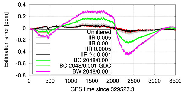
While the estimation error introduced by this low-bandwidth and high group delay filter was significant especially at fast temperature changes before and after the temperature turnaround point at 2067 s into the run (Figures 4 and 5), the forward-backward filtering cancels a major part of that delay. Note that this filter has even lower bandwidth (Table 1) than the same filter used in forward-only filtering, as the resulting magnitude response squares with the forward-backward filtering approach.
Figure 4. Temperature-based estimation of oscillator error.Figure 5. Error in temperature-based estimation of oscillator error (note the larger error due to filter delay).
Only a slight performance decrease can be seen when using a boxcar filter with 2048 taps, but only when compensating for the FIR part’s known group delay of approximately 1 s. It is noted that filters #4 and #6 — which show best performance — are only usable in post-processing or with significant latency.
In contrast to group-delay compensated filters, which might not be applicable in low-latency, real-time applications, the even lower bandwidth 1-tap IIR filter — although introducing a still significant group delay — resulted in best tracking performance amongst the filters, which are not compensated for any group delay. This filter’s performance is surprisingly followed by the low-complexity 1-tap IIR filter (#3) ahead of the filters implementing the boxcar (#5) or brickwall (#7) filter blocks. The reasoning for this lower performance — given the results of the equal coefficients but group delay compensated filter (#6) performance — can be found in the higher delay of the measurements compared to the group delay compensated filter. The difference between boxcar and brickwall filter was found to be negligible with this data set.
In general, the receiver was able to provide very good carrier-phase tracking using all of the proposed filters. The satellite signals were tracked with a PLI of better than 0.86 between 98 to 99.8 percent of the time, depending on the implemented filter; this corresponds to approximately 30 degrees phase error or 2 cm ranging error at the L1 frequency.
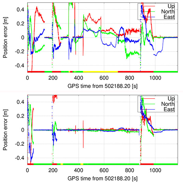
Short baseline test. Both receivers correctly fixed the ambiguities within 150 s, kept the ambiguities fixed until the end of the data set, and computed the correct position with an estimated accuracy of better than 1 cm in each axis. The position estimate error is comparable between the two receivers, and slightly higher than in the zero-baseline test because multipath errors are no longer removed. Figure 6 shows the position estimates errors for both receivers. No significant systematic errors are evident in the position errors from these tests. The slowly varying error in height is typical for multipath signals.
Figure 6. Short baseline position estimates error for TSMO (top) and TCXO (bottom) based receivers. The color bar at the bottom denotes the ambiguity status: all fixed ambiguities (green), partially fixed ambiguities (yellow) and float-only ambiguities (red).
The double-differenced phase residuals are slightly higher for both receivers than in the zero-baseline test (not shown), but follow the same trend for both receivers and are therefore accredited to the signals or processing software rather than to the oscillator.
The phase-lock indicator values for all satellites are visualized in a cumulative histogram in Figure 7. Because the TSMO based receiver’s PLI values are on average slightly smaller than for the TCXO based receiver, higher noise is expected in those measurements. Nevertheless, in the processed data sets, this has no significant effect on the estimated position.
Figure 7. Cumulative histogram of PLI values for TSMO and TCXO-based receivers in short baseline test.
Kinematic Tests
The first test was performed on paved rural roads. Any road unevenness was avoided where possible, or driven over fairly slowly where unavoidable. The test started with an approximate 150 s static time to assure initial fixing of the ambiguities, and continued with driving in open-sky and occasional foliage environment.
As visualized in Figure 8, both receivers were able to fix the ambiguities correctly within roughly 30 s. During the test, both receivers fell back to partially fixed or float ambiguities. The TCXO based receiver computes a partially fixed solution between 650 s and 1200 s, as apparent from the position errors in Figure 8. In the same interval, the TSMO based receiver computes a float-only solution.
Figure 8. Smooth driving road test position estimates error for TSMO (top) and TCXO (bottom) based receivers.
Bumpy Driving. The second test route was chosen to include several locations of road unevenness and a slightly elevated bridge (bump) over a small stream, which was driven over at five different speeds, ranging from approximately 20 to 74 km/h.
Both receivers were able to compute a sub-meter accurate position during the entire test. While the TCXO based receiver was able to compute a fixed ambiguity position with centimeter-level accuracy during the majority of the test, the TSMO based receiver was able to fix the ambiguities at significantly fewer epochs and reverted to a float ambiguity most of the time, decreasing positioning accuracy to the decimeter-level. From Figures 9 and 10 the times of higher acceleration (>5 m/s) when driving over the bridge (between 260 and 490 s into the test) correlate well with the times of reduced number of fixed ambiguities, and therefore times where the navigation engine is reverting to a float ambiguity carrier-phase solution.
Figure 9. Bumpy driving road test position estimates error for TSMO (top) and TCXO (bottom) based receivers.Figure 10. Bumpy driving road test number of total and used satellites, and vehicle excess (>5 m/s) accelerations for TCXO based receiver.
At approximately 562 s into the test, the vehicle hit a larger puddle on the dirt road resulting in high vertical acceleration (> 1g). Despite this high acceleration, the TCXO based receiver stayed in fixed ambiguity resolution mode, and the TSMO based receiver continued in partially fixed ambiguity solution mode.
At 875 s into the test, the car passed underneath two separated two-lane highway bridges, which led to a loss of all signals on all receivers, including the reference receiver. Both receivers reacquired the signals after the underpass and fixed the ambiguities again after approximately 100 s.
Conclusion
Temperature-measurement filter implementations were presented that outperform the previous low-complexity implementations, but at the cost of higher computational requirements, more latency or even real-time capability because of the more complex design or non-causal filtering approach. Using the proposed filtering approach, the eight strongest satellites were tracked in phase-lock tracking state for 98–99.8 percent of the test time, while performing a full hot-cold temperature cycle.
Furthermore, we showed the performance of traditional double-differenced carrier-phase positioning using a receiver with a temperature-sensing MEMS oscillator. Static and kinematic tests were performed, and the operation of an otherwise identical TCXO based receiver at the same time allowed to compare the oscillator’s performance in several environments as well as their sensitivity to accelerations. Carrier-phase positioning with TSMO based GNSS receivers was possible with accuracies better than typically required for automotive applications.
Manufacturers
The temperature-sensing MEMS oscillator was produced by Sand 9, which has been acquired by Analog Devices, Inc. A NovAtel 701GG geodetic-grade antenna was mounted on the test vehicle and a NovAtel SPAN-SE was the reference receiver. A NovAtel ProPak-V3 was the base station, with a Trimble Zephyr antenna.
Bernhard M. Aumayer is a Ph.D. candidate in the Position, Location and Navigation (PLAN) Group in the Department of Geomatics Engineering at the University of Calgary. He worked for several years as a software design engineer in GNSS related R&D at u-blox AG.
Mark Petovello is a professor in the PLAN Group, University of Calgary. His current research focuses on software-based GNSS receiver development and integration of GNSS with a variety of other sensors.
This article is based on a technical paper presented at the 2015 ION-GNSS+ conference in Tampa, Florida.
Skyworks Solutions, which manufactures analog and mixed-signal semiconductors, has launched three low-noise amplifier (LNA) front-end modules with integrated filters for GNSS. The devices are designed to provide high linearity, excellent gain, a high 1-dB input compression point and a superior noise figure.
The pre-filters provide the low in-band insertion loss and integrated notch filtering for excellent rejection of desired frequency bands.
Each device is supplied in small-footprint, surface-mount technology multi-chip module packaging — 1.1 x 1.5 x 0.7 millimeters for the SKY65713-11, and 1.7 x 2.3 x 0.7 millimeters for the SKY65715-81.
The SKY65713-11 and SKY65715-81 both support products integrating GNSS functionality such as smartphones, personal navigation devices, wearables, machine-to-machine (M2M) systems, base stations, asset tracking instruments, professional radios and Internet of Things (IoT) applications. Both are designed for BeiDou and GPS receiver applications.
The ION GNSS+ 2015 Conference once again fielded a jam-packed agenda of papers on subjects from world-wide constellation updates, through GNSS integrity, indoor navigation demonstrations, multi-constellation/function chipsets, interference mitigation and jamming detection, privacy issues, and many other very interesting subjects. That’s GNSS+ in the conference name, as in “plus,” denoting the many other positioning, navigation, and timing technologies it covers.
Most papers contained advanced academic research, but there were also several new industrial releases. This year ION divided and clearly differentiated sessions between “System and Application Tracks,” that is, those with more direct industry content, and “Peer-Reviewed Tracks,” the so-called “pure” research.
As always, some of the most valuable takeaways of attending ION come from the numerous unrelated, off-the-record corridor conversations: an essential element, always spontaneous and much anticipated, but something that cannot be clearly identified nor put into the program.
The conference seemed to have around the same number attendees as last year with about the same number of exhibitors, even though a few of the big booths were missing. Paradoxically, some exhibitors privately said they did better and more business this year, even with fewer attendees, according to their estimates.
SPIRIT Navigation from Moscow did not have a booth, but Ruslan Budnik made sure to fill my notepad with lots about their technology, products and initiatives. They are among several companies working to add indoor navigation capability to smartphones, using existing onboard sensors and new intelligent software. Their solution concurrently uses multiple technologies including geomagnetic fingerprinting, pedestrian dead reckoning, and map matching, but does not rely on an installed beacon infrastructure. A Spirit app allows store operators to quickly map Wi-Fi and Bluetooth signals and collect a Magnetic field map which matches the floor plan of the store’s venue. Spirit claims an accuracy of around 1 meter, which Ruslan proceeded to demonstrate to me in the corridors around the ION meeting rooms.
Theplenary session on Tuesday night was very interesting with a presentation on the results of NASA’s planetary exploration over the last several decades, by Dr. James Green, NASA Director or Planetary Science. I learned a lot about our solar system; much more out there than one suspects, and much to be revealed in the next few years!
GPS World editor Alan Cameron once again led a preview of the planned sessions for the week, with each session chair constrained to a 5-minute rapid-fire presentation aimed at enticing as many attendees as possible. Interesting and somewhat humorous at the same time; we still got a flavor of what was to come in each track.
On Wednesday I was fortunate to be able to interview several show exhibitors. Some of these you will also find in video footage on the magazine’s website, speaking to you straight from the show floor.
Skydel is a relatively new exhibitor, working with Averna, both from Montreal, Canada. Averna makes signal analysis hardware on which Skydel installs software-based simulation of GNSS signals. Skydel’s objective is to be able to make their solution so affordable that every engineer could have one of these record and playback simulators on their desk, rather than having to schedule time on a central, shared multi-function simulator. An exciting new-entry product developed by an energetic group of people with a high level of ingenuity; hopefully they will succeed.
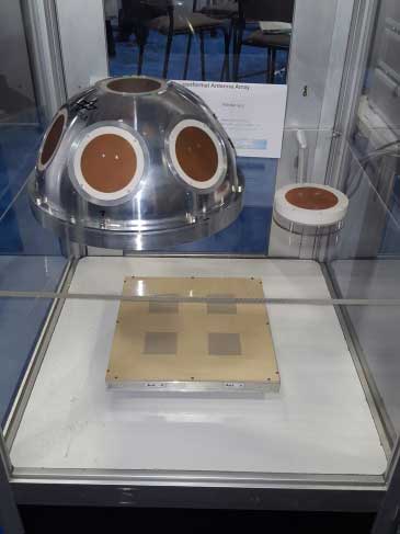
DLR antenna prototypes
A robust receiver initiative from Deutsche Zentrum für Luft- und Raumfahrt (DLR), the German Aerospace Center, aims to demonstrate that jamming and interference detection and mitigation can be achieved much more effectively than just at the RF level. Their processing goes deeper with such features as knowing that a source from a particular direction isn’t aligned with the current constellation, so it’s a jamming/interference suspect. Their conformal antenna development attempts to meld an antenna configuration with their signal processing capabilities. DLR is looking for partners to put these developments into commercial receiver applications.
ComNav has a new K700 family of receivers: K-700 GPS L1, Beidou B1 and Glonass L1 80 channel receiver — added to their K-708 dual frequency 198-channel dual-frequency version. The M300 Pro GNSS Receiver package includes a weather-hardened package, multiple interfaces which enable remote internet control and data access, memory and a rechargeable back-up power supply. ComNav claim the M300 Pro has been selected for the Chinese CORS network. ComNav also anticipates a name change in the near future: SinoGNSS will be their new company name.
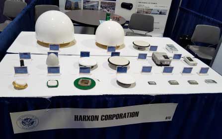
Harxon antennas and radiosUnicore UB370 Beidou/GPS/Glonass multi-frequency OEM receiver
Harxon gave us an overview of their wide range of antenna and radio products, while Unicore in the next booth described their single and dual frequency receivers which they are now promoting extensively in North America.
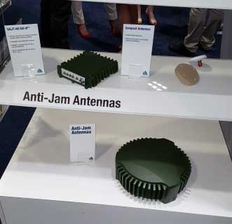
NovAtel GAJT antijam systems
As usual, NovAtel had a wide range of products on display. I was impressed that the mil-spec GAJT anti-jam product-line has now undergone testing by both the U.S. and Canadian military, and that the GAJT-AE is now flying and providing guidance protection in hostile jamming environments. Once again there were mentions of NovAtel receivers and antennas being used for research in several technical papers at the conference.
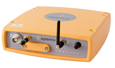
Septentrio continues to make further inroads into the high-precision GNSS receiver market, and announced several new key initiatives. The company has been selected by UNAVCO as the Geodesy Advancing Geosciences and EarthScope (GAGE) facility preferred vendor for next-generation GNSS reference station products. UNAVCO ( ) is a non-profit university-governed consortium, facilitating geoscience research and education using geodesy.
AsteRx-U dual antenna receiver
Septentrio is developing a next-generation reference receiver with UNAVCO’s inputs and evaluation feedback for the purpose of upgrading and renewing their GNSS networks. Septentrio also launched the AsteRx-U and the AsteRx-U Marine multi-constellation dual antenna receivers which incorporate the latest GNSS tracking and positioning algorithms and interference mitigation along with integrated UHF radio, Wi-Fi, USB, Bluetooth, cellular connectivity, and a spectrum analyzer which provides users with their interference profile.
Indoor Navigation
ION’s annual Indoor Navigation Demo session on Wednesday afternoon turned out to have more slides and pre-recorded testing content than actual demonstrations. The participants included Nokia HERE, Rx Networks, SPIRIT Navigation, TRX Systems, Broadcom, Indoors and Combain.
HERE was able to initially demonstrate some indoor tracking of an equipped cellphone, but the display for the audience appeared to quit after a short period. They did provide a link to allow attendees to download their software and try it for themselves.
Rx Networks is apparently focusing on self-location for indoor guidance assets, and ran a pre-recorded demo of ‘Zed’ in a Vancouver Mall – but the vertical tracking display part of the video was completely washed out for the audience.
SPIRIT Navigation ran a recording of the demo I had witnessed earlier – a quite effective, working indoor nav application on a smartphone – and then walked around the demo room, but wasn’t able to show real-time results.
TRX Systems ran a very effective real-time demo and was able to show the audience the path of their ‘walker’ as he meandered around the Conference Center, changed levels and eventually returned on cue to the demo room. They use crowd sourcing to build an initial map which then constrains sensor data from standard sensors, similar to several other presenters. This appeared to be the winning demonstration for this year’s indoor nav demo. We did hear later that they were not using sensors within the smartphone, rather a separate TRX device attached to the belt or the ‘walker’.
Broadcom ran an effective demo, albeit with considerable lag between actual and displayed position and frequent jumps between points, presumably due to the same delay problem. This was attributed to the display system used to present to the audience. They also ran a second short in-room demo which was more effective and more real-time, but apparently not as accurate as TRX from the displayed results.
Indoors also use ‘radio’ fingerprinting with GNSS data as a back-up, and Wi-Fi, BLE, magnetic and inertial data fusion along with dead-reckoning. Their recorded demo was quite effective.
Combain has a system which is required to be world-wide interoperable for machine-to-machine asset location, so they are focused on using cell and Wi-Fi IDs for navigation, with databases containing 64 million Cell IDs and 726 million Wi-Fi location IDs. They claimed accuracies of 200 meters for urban areas and 40 meters for rural. These accuracies are not suitable for indoor location so no demonstration was provided.
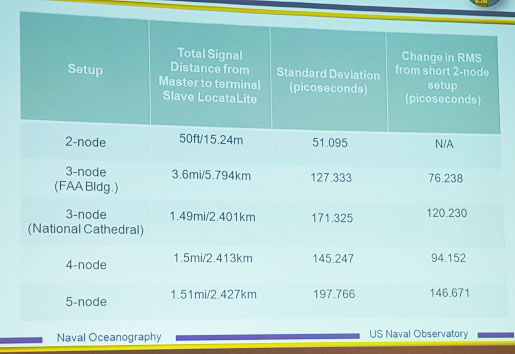
Pico-second test results (Click on the image to enlarge it.)Pico-second test results
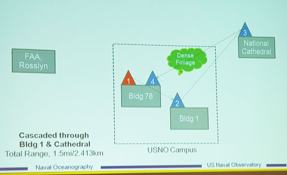
Later, I managed to catch a paper which Locata had recommended, which involved a number of Locata networks used by the U.S. Naval Observatory to demonstrate time and frequency transfer using the USNO Time Standard, with some highly accurate results: picoseconds! This paper forms the basis of GPS World magazine’s October cover story, providing more on these significant time-transfer and synchronization findings.
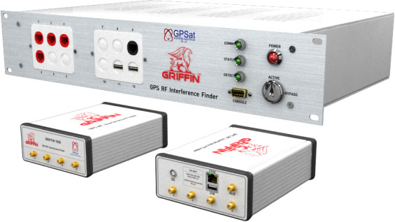
GRIFFIN Central Processor & Node Antenna Electronic Units
Another significant paper was presented in the Interference & Spectrum issues track. GPSat Systems Australia has been working for some time to implement a jammer/interference detection and localization system. The GRIFFIN 1000 system uses both Angle of Arrival (AoA) and Time Difference of Arrival (TDOA) to locate interference sources. GPSat claims that RF interference source in the GPS L1 band can be detected and geo-located to accuracies of a few meters within a few seconds. The system is already in production, with final production field testing underway, and customer deliveries scheduled for November.
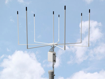
Multi Element Antenna Array and Node Electronics
As ION GNSS+ came to a close for another year, it appears that this GNSS-centric conference is weathering the industry’s apparent preference for other sector shows which may draw new paying customers. ION’s academic/technical content was top-notch as usual, unparalleled anywhere, with attendees flocking to the papers, while existing customers still found comfort in meeting their suppliers on the show floor and around the corridors of the Conference Center. The formula still seems to work for now, but the apparent feeling on the floor was that better exhibitor payback may be found elsewhere, and that this could reduce ION participants in future years. Hopefully not, since this was a very good week for everyone with whom I talked.
The September article Receiver Design for the Future is based on a GPS World webinar, which sprang from a presentation at the Stanford PNT Symposium. Listener questions and Greg Turetzky’s answers during the webinar are provided below. Greg Turetzky is a principal engineer at Intel responsible for strategic business development in Intel’s Wireless Communication Group focusing on location. He has more than 25 years of experience in the GNSS industry at JHU-APL, Stanford Telecom, Trimble, SiRF and CSR.
Is dual frequency expected to be seen in smartphones this year?
If what you’re saying there is L1, L2, L5, the answer is absolutely not. But if what you’re saying is GPS, Galileo, BeiDou, which are all in different bands, then I think we are already seeing tri-bands between the GLONASS band, the GPS band and the BeiDou band. I expect to see that continue from a multi-constellation standpoint, rather than multi-frequency on individual constellations.
How do you see antenna design changing and developing relative to receiver design?
If you go back to that slide, the answer is the opposite — antenna design has been getting worse and worse in order to shave cost and size and is being made up for in silicon design. A really good example is, most GPS receivers that we build for mobile phones aren’t optimized to work at -140 dBm, our standard normal outdoor power, because we never see that. The antennas that we typically work with are 8, 10, 12 dB down, so no matter what, we never see anything above -140.
So I think the answer is the opposite — no one is trying in my market to make better antenna design, they’re trying to make them even smaller and even cheaper. Especially if you think about getting into wearables and button-sized things, you need a GPS antenna, a Bluetooth antenna and a Wi-Fi antenna in a button. That’s the problem, and still leaving room for performance. So basically we’re being asked to make up for that in the receiver design.
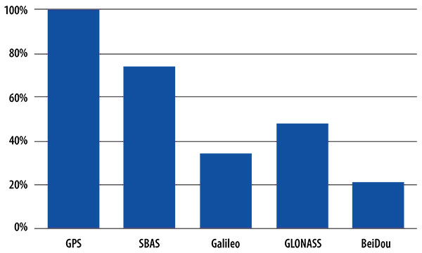
One of your slides showed GPS with 100% penetration, and SBAS was one of the next highest bars on that chart, outdated as it was, even though it’s only less than a year old. What are the benefits of SBAS in a commercial receiver?
The issue with that fact is we like geostationary satellites, because they’re easy to find and they’re useful from a visibility standpoint. But the data demodulation of those is even more challenging than GPS because of the additional coding schemes that go on top of it. It’s very difficult for us to demodulate off the SBAS satellite, so we primarily use them for ranging and for autonomous operation when we’re not aided.
In aided operation, we use them less, because we get the data that we need off the Internet, right off a feed, or it comes in off of a satellite, which is much more useful. So SBAS stuff is there because it doesn’t add a lot of cost of difficulty to the receiver design, but it’s not a crucial part of the operation anymore — I’d say with the exception of QZSS, which has a large impact in its regional operating area.
Let’s continue the trend in questions towards multi-constellations. What’s the strategy to switch on another GNSS constellation in case of a GPS problem for a future receiver?
It’s a really good question, but it comes from a premise that we would switch something on that was normally off. The general strategy that’s being followed is to use everything that’s available all the time, so that we can use the methodologies of essentially autonomous RAIM on a receiver where we now have 8, 10, 12 signals coming into the receiver. It’s pretty obvious right away when something has gone wrong, and so it’s not so much time when we can flag when to switch on. It’s more a time when we can switch off. If we see a systemic problem in multiple satellites, then we may use that in our definition, but it’s not from a switching-on standpoint.
So, basically what we’re doing is we’re keeping everything on all the time and relying on autonomous RAIM capabilities from the fact that we’re tracking 14 or 16 satellites at a time with all this extra compute horsepower, because now I’m running embedded CPUs at hundreds of megahertz, where back at SiRF when we could get 15 megahertz, we were happy. So we have a lot more compute horsepower on the mobile side to do autonomous RAIM.
How the Internet of Things Now Drives Location Technology
The number of devices connecting to the Internet is growing fast. The applications running on them require location context to determine the most likely use case. These devices need continuous location — not necessarily noticed or activated by the user, but always on. The specification that becomes important is energy per day: the device must maintain its location without draining its battery — and increase location availability indoors. That creates new design requirements for hybrid capability.
By Greg Turetzky
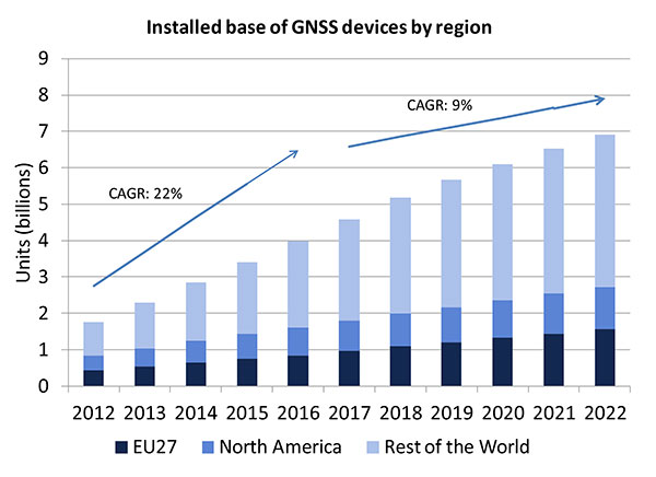
A lot of people have the opinion that the GNSS market is kind of flat. Actually, several different market studies would indicate that it’s not as flat as you would think. See FIGURE 2, taken from the European GNSS Agency’s (GSA’s) 2015 GNSS Market Report. The growth rate certainly is slowing, but any market that continues to grow at a 9 percent annual growth rate is a very nice target area. As you can see, the GSA expects that we’re going to have somewhere in the neighborhood of 7 billion devices within the next eight to ten years.
Figure 2. Installed base of GNSS devices by region; the GNSS market continues to grow at a rapid pace. Source: GSA GNSS Market Report.
We’re getting to the point where the number of GNSS receivers exceeds the population of the planet, which makes for an interesting thought process as to where GNSS is going to end up, and how it’s going to have to end up in everything that we do. That makes for a nice market opportunity. A big reason for that is we’ve seen a lot of growth in demand for multi-constellation GNSS. Everything pretty much has GPS in it that everyone terms as GNSS, but the growth of these other constellations is happening relatively quickly.
FIGURE 3, in my opinion, is already significantly out of date, even though it is less than a year old. Other market estimates indicate that GLONASS penetration into receivers, especially in the mobile phone field, is closer to 70 or 80 percent today, and that is expected to grow. There’s really no technical or economic reason why GNSS receivers can’t support multiple constellations, even at the consumer mobile device level.
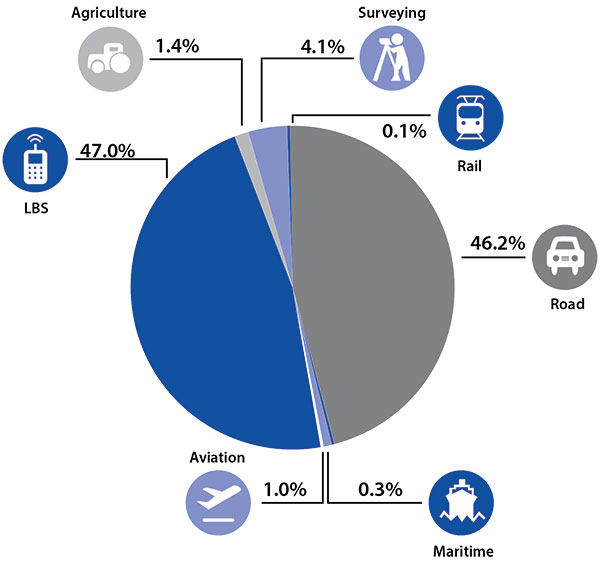
Once all those constellations are in place, let’s look at where those receivers are going from a market standpoint. FIGURE 4 is divided by revenue, which is an interesting way to do it because we all know if you divided it by actual units, then the location-based services (LBS) portions in phones would dominate everything; everything else would just be a sliver that wouldn’t be visible. But if you look at it from a revenue standpoint, there are still many revenue opportunities in the phone segment and in the automotive segment.
Another reason to expect continued market growth is, if you examine Figure 4, you’ll notice that the Internet of Things (IoT) category (see SIDEBAR) doesn’t even show up here. We’ll see going forward that there will be a new slice of pie showing a focus on that segment and those types of applications.
Intel and the Internet of Things
Intel’s mission is no longer only to build PCs. We’re about bringing smart, connected devices to everyone. That encompasses a range of products, and we’ve been expanding our portfolio appropriately.
We start with everything from big iron data centers (which are part of smart devices) to mobile clients and all the way down to the Internet of Things (IoT) and wearable devices. All those devices are part of this smart connected world. Our group’s job is to help on the connectivity side, which varies by product.
This whole idea expands beyond mobile phones and into the IoT, a big trend whose methodology is transforming business, starting at sensors all the way up to big data, to make interesting decisions. The number of devices that are being able to connect to the Internet is growing faster than anybody can keep up with, and that creates a really interesting opportunity. That gives you a bit of a picture as to why Intel is interested in this market and where you’re going to see us playing.
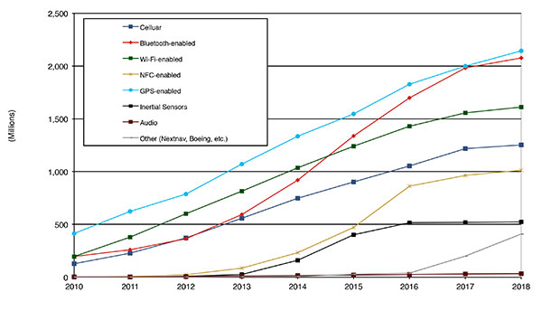
Looking at how we provide this location capability beyond just GNSS, how are people determining their location in these different platforms, and what are the different technologies available? FIGURE 5 shows that in 2014–2015 the most popular technology is still GPS, but there is a fast-growing trend in both Bluetooth-enabled and Wi-Fi-enabled penetration of location technology. Both of these are more suited to indoor operation, where the market is still in its early stages.
Figure 5. Alternative location technology shipments, world market forecast: 2010–2018. Source: ABI Location Technologies Market Data.
Although GNSS continues to grow with market growth, the growth of other technologies and the ability to incorporate them into location solutions is growing pretty quickly, and the radio versions of those are, in general, growing the fastest, followed by the inertial sensors. I think we’re going to see this combination of location technologies, jointly providing a single answer, becoming the norm in mobile products.
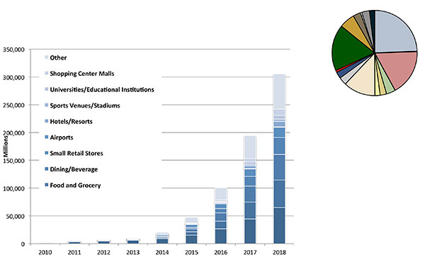
These technologies are going to end up, especially for indoors, in different areas. FIGURE 6 shows a huge growth, not only growth but segmentation among a bunch of different types of venues, all of which seem to be adopting an indoor location methodology. Not all of them will adopt the same one, but all these types of venues are looking at that market and are looking at potential different technologies to serve their needs. What might be most appropriate in a grocery store — geared towards finding a particular item — like a Bluetooth beacon might be less interesting in an airport, where there’s still a need for navigation from place to place, where proximity is not necessarily the right answer.
Figure 6. Indoor location technology installations by vertical market, world market forecast, 2010–2018. Source: ABI.
We see a large growth of a very disparate technology base; at the right of the figure is a pie chart where I had to remove all the callouts, the list of all the different technology suppliers addressing these particular indoor markets. What you see is a highly fragmented supplier base; that’s very consistent with an early market implementation. There’s a lot of different people attempting to get into this market with a lot of different solutions. This is pretty classic for an early-adopter scenario.
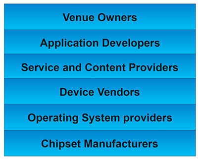
The Stack. Changing accuracy requirements will come up a bit later in this article. Once we’ve looked at where those different venues are from a requirements standpoint, we start to look at the types of companies that are trying to participate in the ecosystem required to do that (FIGURE 7). If you start from the bottom, where I live as a chipset manufacturer, and you move up the chain, you see seven different layers of people in the creation of a location to the end user, especially indoors. And every single person you see in this value chain is trying to make money.
Figure 7. LBS value chain: a highly complex ecosystem with each segment looking to differentiate and monetize indoor location. Source: GSA GNSS Market Report.
That’s the crux of the issue: a lot of people want a piece of that pie, and all of them have a relevant part to play, but when seven people in the stack are all trying to own the location result in order to monetize it, it becomes difficult to create a unified methodology. I live at the bottom of this complex ecosystem, in the technology implementation layer. Getting dollars to flow from the top to the bottom gets relatively difficult, so we are very driven to bring cost competitiveness into this market.
In summary, from a market standpoint, we see that the market opportunity is very big and still growing. This makes it interesting to a company like Intel, even though we aren’t a major player in the business today, to continue to invest in it. We see a trend going from GPS to GNSS and on to location, and now the big opportunity is indoor location. But this indoor-location market is not a stand-alone device opportunity. Indoor location requires this kind of technology inside other devices, inside phones and tablets and IoT types of things.
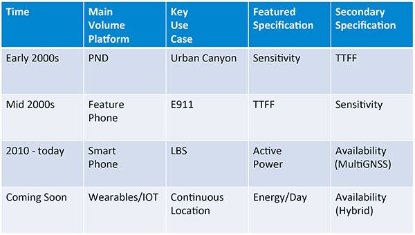
Context. Let’s look at indoor location as a feature in a larger portion of product. That idea comes from the requirement for location not just for the location itself, but in order to provide context. That’s critical because now these smart, mobile devices are not just used to make phone calls, but are used all the time. As a result, many applications running on them really require that location context to determine the most likely use case that the device is currently operating, making the consumer experience easier and more natural. This is evident throughout the entire value chain from phones and tablets to wearables. If you think about that from a requirement standpoint, you see the major places where GNSS has enabled trend changes in the market.
Let’s step back a bit in history to go through FIGURE 1, the opening figure, horizontally. In the early 2000s when I was at SiRF Technology, the main market drivers were personal navigation devices (PNDs). There were all these dashboard-mounted PNDs, and the main things we were trying to fix was the urban-canyon problem. GPS always worked well in the rural areas but always had trouble in urban canyons; to fix that, we had to improve the sensitivity. The solution in that timeframe was with multi-correlator designs and improved RF frontends; we were able to improve the sensitivity of the receivers by a good 5–10 dB, which enabled us to really keep the antennas inside the car so that there was no need for roof-mounted antennas. The PND could be mounted on the dash and work just fine. That was a big factor in improving the user experience. The secondary specification that enabled that market to grow quickly was time-to-first-fix; those devices had to power-up and work fast to prevent user frustration.
Within about five years, however, the PND market was overtaken by growth in the feature phone market. The reason for that was the FCC E911 mandate; everyone had to figure out a way to make sure that phones sold in the United States had the ability to meet that 911 mandate. GPS was one of the major methodologies in meeting that, and the main driver there was not around sensitivity, it was improving first-fix times. The mandate required a 30-second TTFF implementation in a very challenged environment to support emergency-services dispatch. This led us to the development of assisted GPS (AGPS) and further integration into phones. We had a secondary requirement of continuing to improve the sensitivity, because now we had to deal with an even worse antenna in a handset.
Once that was taken care of in the mid 2000s, the next thing we saw coming — and what’s coming now — is the change in GPS requirements for smartphone navigation. This comes from the huge growth of higher end smartphones that are running multiple applications driving the use-cases around LBS. How will the location be used to provide services, now that we can provide applications on that platform? Now the most important specification has become active power? Every time a GPS receiver is turned on for use in an LBS mode, you have to make sure that the power consumption is kept to a minimum, or no one will use those services. So the active power of the device became a very important specification that we were all trying to improve.
The secondary specification we had to improve was the availability. This is where the advantage of multi-GNSS started to show up — using handsets for car navigation on Google map types of implementations. So the performance of smartphone navigation in the urban canyon became a big driver recently as the main use case.
Impacts of New Requirements on Silicon Design
Standby power reduction impacts
SRAM is the leakiest component of typical design
Needs to be reduced or ideally eliminated
Non-continuous fix methods
Ability to quickly save and restore state information
Hybrid location solutions
Support measurements from multiple radios
Need to share radios, not duplicate chains
Increased integration of of multiple radios on single die
Need more interference rejection capability
Ability to support concurrent radio operation on single die
Next! What’s coming next is the idea that these wearables and IoT platforms are not just doing LBS on demand because of the currently active application. They are going to need continuous location. The device needs to provide location capability all the time, but it’s not necessarily going to be noticed by the user or activated by the user, so the specification that becomes important is energy per day. You want to make sure your device can maintain its location without draining its battery. Then we are also going to have to increase the availability of location into indoors to really fix this whole problem. And that will really move us into hybrid capability.
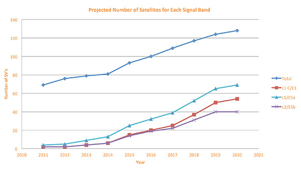
If we look at those changes in the market and we look at how they’re going to impact the GNSS architecture, the first thing we want to look at is: Where is GNSS? FIGURE 8 is a plot that I’m sure everybody has and is hard to keep up to date. It looks at the satellites coming from the different satellite constellations. The important thing here is that we are approaching a timeframe where a significant uptick in the growth of satellites can send the numbers over 100. That can really have an impact on receiver design, if you’re building a multi-GNSS receiver and you have to deal with a hundred satellites. How are you going to do that?
Figure 8. Projected number of satellites for each signal band.
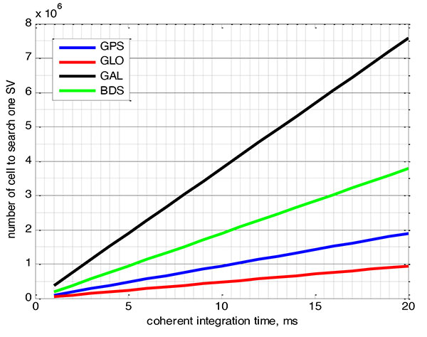
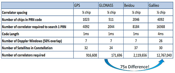
FIGURE 9 shows the relationship between the coherent period and the number of correlators required to search for one satellite in each constellation. We looked at particular scenarios — in this case, let’s say we are trying to do an outdoor location, so –130 dBm cold start test (FIGURE 10) with an initial frequency certainty of around 1 part per million (ppm). We wanted to look at the impact of the different constellations on doing that, and what it takes inside of the receiver to implement it. I’m not going to go into great detail here. But looking at those impacts in correlator counts, you can see the difference between building a GPS receiver that can do this and building a Galileo receiver that can do this. From the simplest one, that is, GLONASS, and from the most difficult one, which is Galileo, you see a 75x difference in the number of correlators required to do that, based on signal structure. This would indicate that, maybe from a cold start fix point of view, you might prefer a GLONASS implementation, and do GPS or Galileo later.
Figure 9. Relationship between the coherent period and number of correlators requried to search for one satellite in each constellation. ±1 ppm local oscillator frequency uncertainty; ±10 kHz Doppler shift range; 50 percent Doppler bin overlap; 1/4-chip correlator spacing.Figure 10. Test scenarios, cold start test.
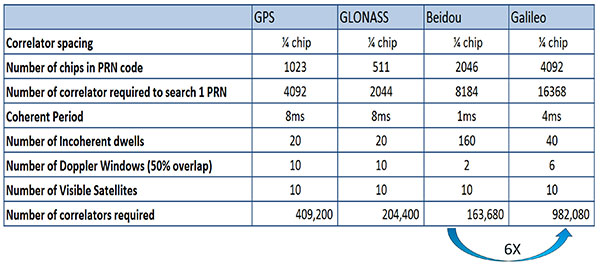
If that specification was your primary concern, then you would look at how those requirements got implemented into those devices. In addition, you try to come down to these low levels of power consumption, maintain sufficient accuracy to support these applications, and be able to move this into a very small form factor. If we look at the relationship between the number of correlators required to search for each satellite and amount of silicon area that requires, we see a big difference in the growth of those, depending on which constellation you look at. But if you look at a hot start scenario (FIGURE 11) rather than a cold start and at a weaker signal level, which is the more common implementation in devices today, you see a different result. With an improved starting condition because we have better information on the oscillators and reduced other uncertainties producing a smaller search space, the silicon area impact is greatly reduced. Then we have to really look at reducing standby power. That means we need to look at static random-access memory (SRAM) because SRAMs are a horribly leaky component and create very large standby power, but they are what we’ve been using for years in the standalone GPS world.
Figure 11. Test scenarios, hot start test.
We also have to look at non-continuous fix methodologies: this idea of turning things on and off to save power, which relates back to the standby power issues. We also have to look at hybrids: How are we going to support measurements from multiple radios like Wi-Fi and Bluetooth that are becoming important for indoor location? How are we going to share those radios without just pasting them together? That involves integration onto single die, and looking at what happens on the silicon level, and at what happens when you try to run radios at the same time.
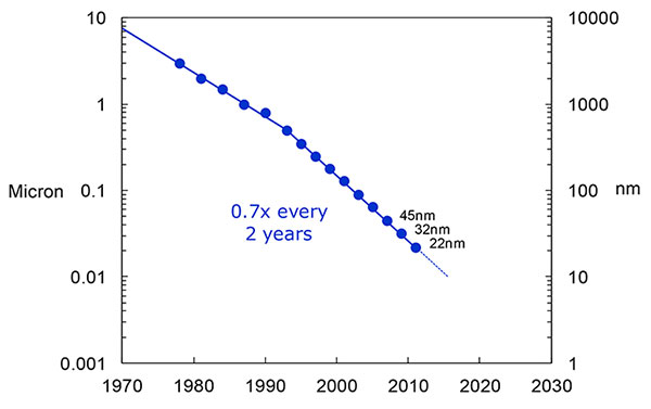
What we have to work with, especially here at Intel, the home of Gordon Moore, is Moore’s Law. It is still working 30 years after it was proposed. Recently, we see that we are tracking this progression of constantly reducing device sizes and moving forward. The dates in FIGURE 12 are for the process technology nodes associated with a classical digital process. We are not at the 22-nanometer level today on GPS receivers, but we are moving down that curve.
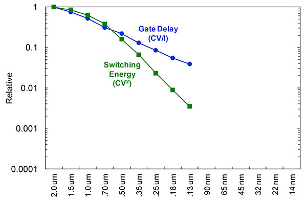
Figure 12. Moore’s Law in action: transistor scaling and improved performance. In GNSS terms, this means more gates and more memory for less cost, improved TTTF and sensitivity by allowing more search capability.Figure 13. Scaling also increases speed and reduces power. HIgher clock speed provides better search and more complex navigation algorithms.
Obviously, when you move down that curve, you greatly increase your ability to add more gates to improve TTFF and sensitivity. More correlators help you search out more uncertainty faster. The other thing this does is allow us to run faster, to up the central processor unit (CPU) clockspeed. This allows more software capability to do things like process more advanced navigation algorithms, bring in more satellites from multiple GNSS, run very expansive Kalman filters, and look at hybrid technologies. It has also driven down the power, so that reducing the active power requirement that we had was kind of coming along with Moore’s law without a whole lot of effort.
But now we’ve run into a problem: the parameter that we care more about, standby power, is actually going up. Although we are getting benefits out of Moore’s Law from speed and active power, we are actually having a problem. It’s increasing our standby power, which makes it difficult to go to these lower fix rates with faster restarts.
You see a trend here. As you move down in technology nodes, you find that the more advanced technology nodes are less applicable to the smaller multi-purpose devices. This is part of the reason why you don’t see the mobile phone devices coming down as fast as you see the desktop devices coming towards those new technology nodes.
This means some really significant silicon design challenges. We need to figure out how to take the advantages of Moore’s Law and maintain the benefits of smaller geometry, we need higher clock-speeds, and we need more memory for multi-constellation methodology and that gets lower active power and smaller size.
But we have to figure out a way to not give up our standby power when we start moving down into these very small geometries. That will require some new methodologies, both at the chip level in terms of how we build silicon, and at the system design level, in terms of how we put these things together inside a mobile phone.
What Intel Is Doing
I can’t tell you what we haven’t done yet, but we look at location as an opportunity where the strength of Intel comes into play. We have very advanced silicon processors and we are bringing those to bear on the location technology problem — just starting in the last few years. Our goal is to provide a GNSS and location silicon solution with best-in-class performance based on Intel technology. Once we’ve done that at the silicon level, we’ll look at bringing the platform-level integration capability together.
We have the ability to merge multiple location technologies. We have a platform-level capability to integrate hardware and software to solve the indoor location problem on a variety of platforms. To execute to Intel’s vision, we’re going to push this into a ubiquitous technology present in all these devices, so that we can improve the variants on these mobile products.
Multiple Radios. That’s part of what’s driving the whole industry towards the kind of consolidation that we’ve seen: stand-alone chipsets are not the only (or even the preferred) way to solve this problem. Without some access to the system design level, we’re not able to solve this problem for mobile phones and IoT type devices. We’re going to see this trend — that we all see coming — of putting multiple radios onto a single die, because that does reduce cost and size as we try to get into watches.
The 2015 Consumer Electronics Show brought out the new stuff. They’re talking about IoT buttons. We still have a ways to go; bringing that capability down to that size in a GNSS radio is a difficult problem. Once we start incorporating these different radios, such as Wi-Fi and Bluetooth, into this solution, we run back into the problem of the value chain: How to get everyone aligned in a device with these capabilities into a single unified solution?
One of the problems a lot of us see with these mobile products is that they have a lot of application and they require a lot of interaction. We’d all like these devices to become smarter and present the information that we want, when we want it. A big part of that is the location context, and so that’s what we’re planning on doing: integrating that location context into all these platforms so that these smart connected devices can be even smarter and provide a better user experience.
GREG TURETZKY is a principal engineer at Intel responsible for strategic business development in Intel’s Wireless Communication Group focusing on location. He has more than 25 years of experience in the GNSS industry at JHU-APL, Stanford Telecom, Trimble, SiRF and CSR. He is a member of GPS World’s Editorial Advisory Board.
The statements, views, and opinions presented in this article are those of the author and are not endorsed by, nor do they necessarily reflect, the opinions of the author’s present and/or former employers or any other organization with whom the author may be associated.
This article is based on a GPS World webinar, which sprang from a presentation at the Stanford PNT Symposium. Listener questions and Greg Turetzky’s answers during the webinar, which can be read here.
The author would like to acknowledge the contribution of Figures 9, 10 and 11 from the paper “Optimal search strategy in a multi-constellatoin environment” by Intel colleagues Anyaegbu et al, from ION GNSS+ 2015.
Anticipating New, Different Application and User Needs
Users in emerging applications may have different requirements from traditional high-precision users. New users increasingly look to the technology not solely for position, but to navigate them through the environment, often autonomously or semi-autonomously. Tracking all of the new multi-GNSS signals, and then using the large number of inputs in the positioning engine, drives the amount of processing power and memory required onboard the receiver. These in turn drive the cost, size and power consumption of the receiver in exactly the opposite direction from the expectations of customers.
By Jason Hamilton
In considering the future of high-precision satellite navigation, we need to consider what users of the technology are trying to accomplish, and which growing and emerging applications will drive adoption of GNSS technology in the future. These applications will drive growth in our industry if we can correctly anticipate their future needs.
Traditional applications of high-precision GNSS are well understood, but what these customers have demanded from GNSS can be at odds with what users in emerging applications require. Survey and mapping users were early adopters of high-precision GNSS and remain large user segments. Surveying with GNSS requires the very best accuracy that GNSS can achieve. Every centimetre of accuracy matters. Power and size are important product attributes to survey manufacturers. Mapping customers increasingly are asking for not just position, but orientation of a camera or other sensors.
Once accuracy challenges were well in hand, the topic of availability came into play. It was no longer good enough to have an accurate position in open-sky situations. Applications demanded continuous positions that were accurate in more and more corner cases and challenging environments.
In addition to using GNSS to measure location in an environment, new applications are increasingly looking to the technology to navigate them through the environment — often autonomously, or semi-autonomously. For these users, whether operating on a farm, in a mine, on the ground, or in the air, position accuracy is only part of the requirement. Solution accuracy of course matters, but other receiver attributes such as real-time quality control and solution integrity monitoring, are equally or more important.
Multi-constellation, multi-frequency GNSS provides tremendous opportunity and also presents significant challenges for receiver manufacturers. Constellation and frequency support has previously been a differentiator among high-precision GNSS providers, and among product generations. The relative stability of the satellite constellation definition means that the signals broadcast from space will be relatively predictable for some time into the future, and as such, GNSS products are increasingly supporting “all in view,” the ability to track everything that is broadcast.
The benefits of more satellites, more frequencies (and resulting frequency combinations) and modern signal structures have been well publicized. As new and modernized GNSS constellations come on line, they will deliver more robust positioning in increasingly challenging environments such as urban centers, open-pit mines and under tree cover. We will be able to account for atmospheric effects more accurately, which will help during times of high ionospheric activity and extend the length of RTK baselines. Users have a great deal to look forward to from their next-generation receivers.
All of these improvements necessitate pretty dramatic changes in receiver design. Tracking four global constellations and numerous regional SBAS systems increases the complexity of tracking and positioning firmware and algorithms. Tracking multiple frequencies and signal types on each of these constellations drives the receiver channel count up substantially. The days of the 12-channel receiver are gone. Channels, typically implemented within the manufacturers’ custom chips, drive application-specific integrated circuit (ASIC) complexity, which drives cost, power consumption and physical size. Some of this can be mitigated through the use of smaller process geometries, embedded processors and peripherals, and RF chip integration; however, there are down-stream effects to all of these signals as well.
Challenges
Once your receiver has enough ASIC channels to track all-in-view, you need to do something with all that data. The receiver’s tracking sub-system generates code (pseudorange), carrier-phase and Doppler measurements for every signal on each satellite. With four global and multiple regional constellations and up to four frequencies on each satellite, that amounts to a great deal of data. These measurements are what we turn into position, through a range of different positioning algorithms from code positioning to real-time kinematic (RTK) to precise point positioning (PPP). Tracking all of these signals, and then using the large number of inputs in the positioning engine, drives the amount of processing power and memory required onboard the receiver. These in turn drive the cost, size and power consumption of the receiver in exactly the opposite direction from the expectations of customers.
Bandwidth. Communications bandwidth is also a future challenge. Positioning methods, such as RTK, that transmit base-station observations for each GNSS signal to field rover receivers, will require much more bandwidth in the all-in-view future. PPP, which provides a state-space correction of the underlying GNSS error sources, is a promising alternative to RTK that scales better with more satellites than RTK and provides performance that is good enough for many applications.
Utilizing the multiple frequencies available from modern constellations also presents challenges to receiver designers. RF designers are faced with the opposing challenges of making GNSS receivers and antennas smaller, lighter and lower cost, while also supporting more GNSS broadcast frequencies and mitigating against increasing amounts of interference in the L-band RF spectrum from non-GNSS uses. Robust RF design makes the difference between a system that works most of the time, and a system that works reliably all of the time.
Expectations
If we now come back to the expectations of end users, the challenges are clear. Most customers actually don’t care about all-in-view tracking, how many satellites are tracked, or about what the receiver is up to behind the scenes. Users will judge their GNSS receiver on whether or not they are receiving a position that meets the requirements of their application. Are they meeting their targets for accuracy, availability, latency, data rate, and does the receiver fit from a size, power consumption, regulatory and cost perspective? After a certain level, more observations do not make the solution more accurate or more robust. Manufacturers need to carefully manage the tradeoffs in their systems on behalf of users to produce the best quality position possible, while still meeting the customer expectations on all the other receiver attributes.
Sensor Fusion. Demands of new applications drive GNSS providers to consider more than just position. Most vehicle control applications require orientation information as well as highly accurate position. Multiple-antenna GNSS heading systems are becoming smaller than ever. Inertial measurement device technology is also evolving quickly. Miniature micro-electro-mechanical systems (MEMS) inertial sensors can now deliver performance that only a few years ago was exclusive to large, heavy, bulky systems. The integration of GNSS and inertial technologies has been well adopted in highly demanding applications like aerial and ground mapping. As the size, weight and cost of the technology continues to shrink, sensor fusion in many forms will become the standard for all machine control and autonomous vehicle applications.
Safety. This is a key consideration for system designers working on remotely or optionally piloted and autonomous systems. Position and orientation accuracy is important, but so, too, is assuring that the solution is right and can be trusted. The accuracy of the solution needs to be characterized in real time so that control systems can react as necessary to protect users on and around the vehicle. Often in these applications, accuracy can be traded off against the robustness and reliability of the solution. This presents new ways of thinking for firmware and algorithm developers who have focused for so long on solution accuracy.
Support. Lastly, let’s not forget having reliable supply of high-quality product, and expert customer service to back it up. As high-precision GNSS attracts new users in a range of new industries, they are less often geodesists or geomatics engineers. The products absolutely need to be easy to use correctly, backed up by complete and accurate product documentation and supported by world-class application engineers.
Jason Hamilton is vice president of marketing at NovAtel Inc. Since joining the company, he has held a number of research, development and product management roles. Jason holds a Bachelor of Science degree in geomatics engineering from the University of Calgary and an MBA from Royal Roads University.
Parrot’s quadcopter Bebop Drone has Furuno inside.
Furuno Electric Co.’s latest multi-GNSS receiver module, GN-87, has been adopted for the new quadcopter Bebop Drone, made by Parrot SA. Parrot develops advanced technology wireless products.
The GN-87 can receive GPS, GLONASS, SBAS, and QZSS concurrently, which significantly improves positioning success rate and robustness against interferences by using different frequency bands, Furuno said.
Parrot Bebop Drone, equipped with a 14-megapixel fisheye lens camera, takes video and pictures in a 180-degree field. The drone integrates mechanical and digital systems, like shock absorbers that cushion engine vibrations and algorithms for an exclusive 3-axis image stabilization, meaning that the angle of the view remains fixed, without distortion, regardless of the inclination of the drone and movement caused by turbulence. The combination of numerous sensors gives the drone impressive stability and great maneuverability when piloted via Wi-Fi with a smartphone and a tablet, or with its Wi-Fi extender, Parrot Skycontroller.
Furuno’s GN-87 supports sensing for autonomous flying according to flight routes preset on the map application by user, automatic return to takeoff position, recording flight path data for 3D modeling on Parrot Academy map. According to Parrot, selecting Furuno’s GN-87 multi-GNSS receiver module enabled simple integration with a high-performance GNSS receiver module while guaranteeing high quality and high volume supply availability.
u-blox is offering the CAM-M8C — a small, low-profile GNSS positioning module with an integrated wideband chip antenna for reception across the entire L1 band. The module offers simultaneous GNSS operation for GPS/GLONASS, GPS/BeiDou, or GLONASS/BeiDou to deliver accurate, jamming-resistant and reliable positioning anywhere in the world.
The CAM-M8C integrates a u-blox M8 satellite receiver, crystal oscillator, SAW filter and low-noise amplifier. It also has an input for an external active antenna — when using this option, the internal antenna acts as a backup. Because of its design, the module maintains its performance regardless of physical orientation, making the product suitable for mobile applications with frequent change of bearing.
“Where space is at a premium, for example in emergency call systems, in handheld navigation or in wearable devices, the CAM-M8C module offers a very cost-effective way to bring products to market quickly due to its small size and high levels of integration,” said Kim Kaisti, product manager, Product Center Positioning. “It does this without compromising performance or reliability, and leaves system designers free to concentrate on other important aspects of their product development.”
The CAM-M8C is footprint-compatible with u-blox UC530 and UC530M modules, providing an easy upgrade path, the company said. The module is available now.
To further accelerate design and development, an evaluation kit, EVK-M8CCAM, provides a way to become familiar with the CAM-M8C module and assess its performance in specific applications.
The u-blox M8 GNSS receiver antenna module is delivered in u-blox Professional Grade, and is qualified to JEDS47 and ISO16750 standard “Road vehicles – Environmental conditions and testing for electrical and electronic equipment.” The product is manufactured in ISO/TS 16949 automotive-certified production sites, ensuring the high quality and reliability
Telit Wireless Solutions has released a new GNSS module, the SE868-V3. The positioning module combines GPS, GLONASS, Beidou, Galileo and SBAS, which enables the creation of high-performance position reporting and navigation solutions.
The SE868-V3 can navigate to -162 dBm and track to -166 dBm, providing improved performance in harsh environments. It is pin-to-pin compatible with the former SE868-V2 as well as the JF2. This advanced GNSS module can track GPS and GLONASS or GPS and Beidou constellations simultaneously and it is Galileo-ready.
The 11 x 11 mm QFN package contains a powerful baseband processor, SQI Flash memory and GNSS chip with integrated low noise amplifier (LNA). The ultra-sensitive RF front-end enables multi-GNSS indoor fix and high-quality navigation in challenging outdoor scenarios such as dense urban areas, Telit said.
In addition, the SE868-V3 supports ephemeris file injection (A-GPS) as well as Satellite-Based Augmentation System (SBAS) to increase position accuracy. Its onboard software engine is able to locally predict short-term ephemeris starting from data broadcast by GNSS satellites received by the module and stored in the internal Flash memory.
“The SE868-V3 is yet another addition to our positioning product portfolio, which is the result of over 20 years of experience in GNSS applications,” said Felix Marchal, chief product officer, Telit. “Our products are compatible with the GPS constellation as well as its Russian counterpart GLONASS and China’s Beidou.”