RoGO Communications, the creator of the DropBlock satellite communications platform for cellular-denied environments, is partnering with Augmented Sense Technologies (AugSense) to integrate artificial intelligence capabilities into RoGO’s communications infrastructure.
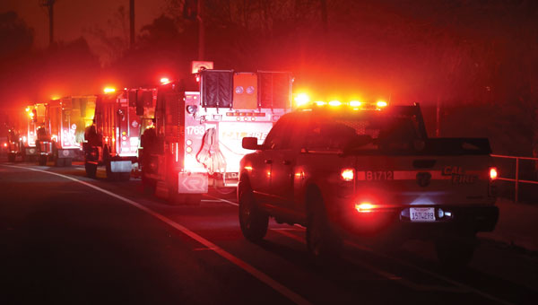
RoGO was founded to develop lifesaving technology for wildland firefighters and first responders. It’s product DropBlock is a ruggedized, portable satellite communications platform that provides real-time GPS tracking, weather telemetry, IoT sensor data, and tactical messaging in cellular-denied and remote environments.
The partnership will develop edge AI-powered sensor fusion, Team Awareness Kit (TAK) ecosystem development, and predictive analytics to firefighters, disaster recovery, military and other first responders and remote operators, including All Hazards emergencies such as hurricanes, earthquakes and floods. Last month, RoGO and AugSense presented the combined capabilities at the annual convention for Special Operation Forces (SOF Week) in Tampa.
Wildland firefighters, search-and-rescue teams, and military personnel routinely operate in remote terrain where conventional communications infrastructure does not exist. RoGO’s DropBlock technology has proven its ability to deliver real-time GPS tracking, weather data, IoT sensor telemetry, and tactical messaging over satellite links in these environments—deployed today by wildland fire agencies. As missions grow more complex and sensor-rich, operators increasingly need more than raw data. AI can deliver intelligence at the edge, delivered in real time, without dependence on connectivity.
Through this partnership, RoGO will enhance its platform with AugSense’s edge AI engine, a modular, platform-agnostic system that processes and fuses multi-modal sensor data directly on devices, without requiring a cloud connection. The AI-enriched intelligence products will transform raw sensor feeds into actionable decisions, such as predictions for the spread of a wildfire or other threats to safety.
Edge AI Capabilities
Edge AI Processing: AugSense’s engine runs AI workloads directly on edge devices using neuromorphic and spiking neural network architectures, achieving greater energy efficiency than conventional approaches. This means intelligence processing in power-constrained environments — no cloud, no data center, no latency.
Multi-Modal Sensor Fusion: AugSense’s fusion engine synthesizes data from diverse sensors (RF, weather, geospatial, physiological, and chemical/biological) into a single actionable intelligence picture at the edge.
TAK Integration & Development: Purpose-built plugins for the Android Team Awareness Kit (ATAK) and broader TAK ecosystem that overlay AI-fused intelligence onto the common operating picture, enhancing coordination across distributed teams connected through RoGO’s DropBlock network.
Predictive Analytics: Machine learning models that transform raw sensor telemetry into forward-looking predictions such as anticipating weather shifts, equipment failures, threat patterns, and fire behavior.
Immediate Applications
The combined solution targets several high-impact use cases.
In wildland firefighting, the integration enables AI-predicted wind shifts and fire behavior models to reach incident commanders via RoGO’s satellite network—critical for crew safety decisions.
For search-and-rescue operations, fused sensor data and intelligent mapping overlays allow distributed teams to coordinate effectively through the DropBlock network without relying on cellular infrastructure.
In defense and special operations, the partnership delivers fused multi-sensor intelligence and TAK-integrated common operating pictures over satellite backhaul in contested and communications-degraded environments.
A new RoGO mobile phone app coming in the third quarter enables point-to-point communications among DropBlocks and firefighter crews and displays the location of firefighting assets along with fire weather data.
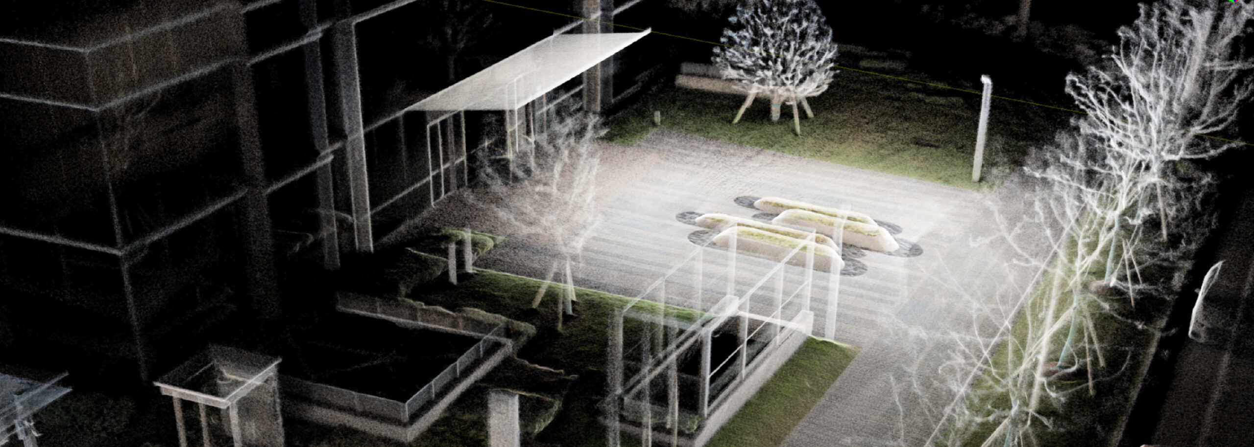
Tersus GNSS has launched the MVP S1 RTK-SLAM handheld 3D laser scanner for mobile mapping and reality capture. The MVP S1 uses GNSS through an AI-driven RTK-SLAM workflow, as well as lidar data with imagery from dual 48-megapixel panoramic cameras.
The combination provides survey-grade results in both GNSS-denied and open environments. The system achieves centimeter-level accuracy outdoors and maintains performance indoors or underground through SLAM processing.
TimeSync 3.0 synchronizes the hardware, aligning sensor data at the microsecond level and supporting consistent datasets and reliable post-processing.
A mobile application provides users with real-time feedback, including previews of colorized point clouds while scanning, as well as basic scan reports on site. This feature helps operators verify data completeness and quality before leaving the field, reducing the need for repeat visits.
The MVP S1 supports 3D gaussian splatting (3DGS), enabling creation of textured, photorealistic 3D models. This capability is useful for building information modeling, construction progress monitoring, underground surveys, forestry analysis and industrial site documentation.
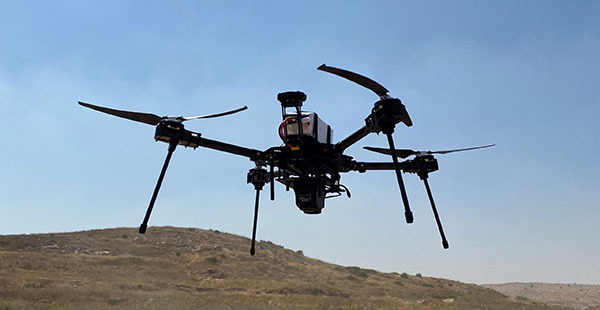
Light and with low power consumption, the NavGuard NOCTA Mini is a fully integrated day and night optical navigation module for jam-proof and spoof-proof operations
Photo: Asio Technologies
Asio Technologies has launched the NavGuard NOCTA Mini, a tiny jam-proof aerial optical positioning system for unmanned aerial systems (UAS).
NavGuard is a real-time optical navigation system that enables seamless and accurate autonomous GNSS-free navigation for tactical UAS platforms in areas where the GNSS signal is spoofed, jammed or unavailable. Using machine vision technology, artificial intelligence, advanced optics and sensor fusion, NavGuard can be installed on various unmanned aerial platforms to enable safe and sustainable 24/7 drone missions under complete GNSS blackout.
NavGuard’s new mini version, NOCTA Mini, is suitable for installation on small UAS. Lighter than other NavGuard systems and with low power consumption, it is a fully integrated day and night optical navigation module for jam-proof and spoof-proof operations.
NOCTA Mini enables UAS to operate beyond visual line of sight from takeoff to landing. Because it is based on machine vision, the system is drift-free. The self-contained system incorporates a computing module, geographic information system (GIS) infrastructure, and day and night cameras.
Designed for applications such as defense, homeland security and infrastructure security, it is a suitable solution for tactical UAS missions where payload capacity and flight time are limited, and continuous operation under all conditions is critical.
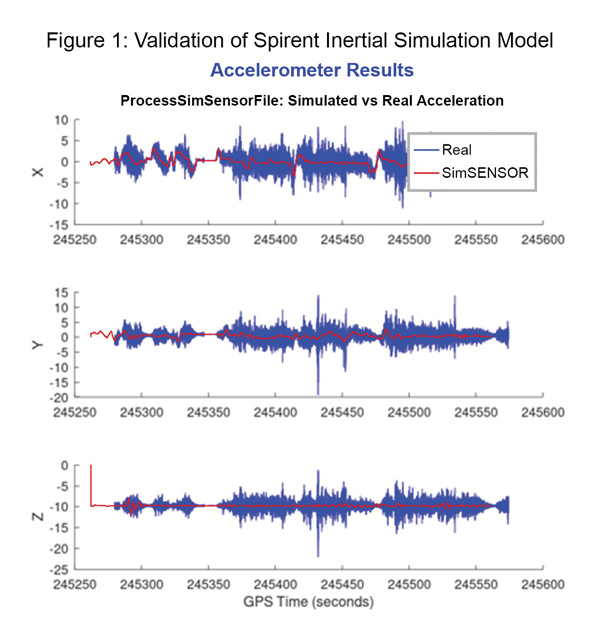
Data shows how successful baseline validation testing of Spirent’s inertial simulation model as compared to real world inertial system performance. Photo: Spirent Federal Systems
We discussed complementary PNT with Roger Hart, head of engineering and Jeff Martin, head of sales at Spirent Federal.
What are some of the most promising approaches to complementary PNT sources and how does simulation technology help?
Roger Hart: The vulnerabilities of GNSS have been recognized. Legacy GNSS are all operating on pretty much the same frequencies and power levels, so, they have some significant common vulnerabilities. There is great interest in finding ways to complement or even replace those capabilities.
Dead reckoning, magnetic and inertial systems have been around for a long time. There are emerging markets to make use of alternative radio frequencies for navigation. In some cases, we are piggybacking on communications signals and deriving PNT from them. In other cases, we are using new PNT signals. A couple that we’ve been focusing on are the alternative navigation systems.
They may be using different orbits, different frequencies, different encoding schemes that set them apart from the legacy GNSS systems, so that, used together, they provide greater resiliency and even stand alone when one or the other system may be affected by interference.
Not to be forgotten is inertial navigation. It’s been around for a long time and is still a standard of navigation. Together with GNSS, it makes it a terrific navigation system. It almost defines complementarity because where GPS is vulnerable inertial can fill in the gaps and where inertial drifts GPS does not. So, paired, they make a very strong system.
At Spirent, we’ve been working with customers to provide a variety of options for both those alternative navigation systems and inertial. Both are a very active field of development and we’re keeping abreast of that.
Jeff Martin: Some good points, Roger. This is something we’ve been engaged in for quite a long time. Since we provide test equipment to the community, it’s critical that we understand what they’re worried about, what the vulnerabilities are. It keeps things exciting, it keeps us on our toes and looking ahead to what’s coming.
What are some of the remaining challenges of integrating GNSS receivers with inertial sensors and, again, how does simulation technology help with that?
Hart: Inertial works by integrating sensor measurements that come in. Therefore, any errors that are present just accumulate over time and can corrupt your navigation solution. So, there’s a strong focus on updating error models and on translating them so that everyday users can use them and get real-life-type performance out of them.
There’s a tendency to think of integrating GPS-INS as putting everything together in one box. There are packages that do that. However, the push now is to go to more distributed systems that are integrated but not packaged in the same box. One example is the all-source positioning and navigation standard that is being developed by the Department of Defense. It will allow you to swap one sensor for another as long as they adhere to the standard. That information all goes back to a sensor fusion engine.
Martin: We have known GNSS simulators well for about four decades. We have been playing in the inertial sandbox for at least a couple of decades as well. This has given us the opportunity to build relationships with the with the key manufacturers and designers of inertial systems. Those relationships have been expanding well beyond inertial to many other sensors and systems that are now coming online. It’s been exciting.
Much work is going into using low Earth orbit satellites for PNT—whether piggybacking on the Iridium satellites or launching new ones. How does simulation help with that?
Hart: It certainly helps with the development of the receivers. The groups that are using these alternative RF and LEO or MEO systems need simulation as they develop the receivers. It gives you the ability to try things certainly before you launch them. At this conference there is considerable interest in making things reprogrammable. We have the NTS-3 satellite, which will be running experiments for different waveforms that can be generated. Even M-code is a step in the direction of giving more flexibility to the signal. It has a lot more flexible cryptography and signal generation than the legacy system with the C/A and P/Y codes.
Our simulation platforms are software based, so we can generate and receive data that can be useful for developing software-defined receivers. It gives you the opportunity to try different waveforms. We have already delivered a satellite-based alternative navigation system simulator. Now, we can build on that one to help the other Leo constellations as they come forward.
Martin: Roger put it well. This is where things get fun. People are concerned with PNT vulnerabilities, so we’re seeing these alternative navigation solutions coming forward. Spirent has done a good job over its nearly 40 years of existence of manufacturing and designing its own hardware and software. It has given us the opportunity to respond quickly. These things are coming fast. People need solutions quickly. We have some solutions already and the platform that we have created gives us the flexibility to develop more. We’re seeing more and more ideas come to fruition and people need to test them. So, this is where it gets fun. We’re excited.
Much work has gone into addressing the enduring challenge of urban canyons. How does simulation technology help?
Hart: Urban canyons are the worst nightmare for GNSS signals. If you’re surrounded by tall buildings, signals are blocked. You may have few or even no satellites in a direct line of sight and many multipath reflections. So, diminished and corrupted signals are available to you. Of course, the more GNSS satellites you have, the better chance you have of getting good signals. But complementing that are radar and vision systems. Those are the ones that will stand out, particularly the vision systems that can read the street signs, see where the curb is, look for parked cars. All those kinds of things will help fill in when you have poor GNSS coverage.
You can observe what’s going on in the environment and simulate it. You can also use our forecasting tool to look ahead.
Martin: This is where things get exciting, isn’t it? In these terrible environments where GNSS is contested—whether it’s an urban environment or one with intentional jamming—there is a lot we can do to help our industry. When this happens in real life, it’s bad news. But when you create that scary situation in the controlled environment of a laboratory, it is great. You can pick things apart and see where you need to improve. I get excited about it. It’s probably the geek in me. It gives us and our partners a lot to look forward to.
How does simulation technology help with sensor fusion?
Hart: It definitely helps you put all the pieces together. You can’t know how your system will work by individually testing each piece. System is the key word here. Simulation enables you to generate the signals and bring them together into a sensor fusion engine. You can test different algorithms. It’s certainly much cheaper and quicker than trying to build this into a product and then test it. Over the decades, simulation has proved itself as a very valuable way in both basic development and integrating the final product.
Martin: That system-wide fusion is where the magic happens.
It sounds like simulation technology—and Spirent Federal in particular—are very much at the center of a lot of the current developments and discussions about complementary PNT. Do you have any final comments?
Hart: As Jeff said, it’s an exciting time. There are many things going on—new technologies, new ways of communicating. It’s a busy time and a bit of a scramble sometimes to keep up with all the new things that are coming.
Martin: People look to Spirent to be their testing resource and it puts us right in the middle of it.
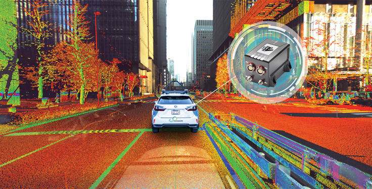
Hexagon | NovAtel’s CPT7 integrates a GNSS receiver and an INS to deliver up to centimeter-level accuracy. (Photo: Hexagon | NovAtel)
We discussed mobile mapping with Bryan Leedham, product manager of enclosures and post-processing software, NovAtel, Autonomy & Positioning division, Hexagon.
How do you define mobile mapping?
It is getting broader in scope, as more folks find reasons to map the world. The key goal is to capture reality from mobile platforms to build a digital representation of reality for some large area, such as a city, a road or a factory. Most of the time, that means from a ground vehicle on public roads.
It’s also safer and faster than traditional surveying because you don’t have to stop traffic or dodge it.
Right! In an ideal world, rather than spending days setting up traditional survey equipment, you could strap some sensors on a mobile platform and gather accurate map data in minutes.
What are the key remaining technical challenges?
Picture one of Google’s or Waymo’s mapping vehicles. The first sensors that come to mind are GNSS, inertial, lidar and radar. Each of those has its own unique strengths and weaknesses. The first technical challenge that remains is to mature each of those technologies for a lower enough cost that it’s affordable.
Right now, mobile-mapping vehicles are quite expensive, especially in areas where some of these sensors will struggle more than others. To map very dense urban spaces — with underground areas, overpasses and tall buildings where GPS is challenged — you need a very strong localization system that can survive those conditions for however long it takes to drive through them. If I’m building a car to map rural Alberta, I could choose much cheaper sensors than if I were trying to map downtown Chicago every week.
On the flip side, you must deal with the massive amounts of data collected.
Yes, that is a very large challenge. Lidar data, in particular, is guilty of generating very large point clouds. It’s a balancing act. More accurate and higher resolution maps require lidar sensors with even denser point clouds. So, you need data management and sufficient processing power to get accurate results quickly.
What are the key technical challenges in sensor fusion?
Sensor fusion is how we approach the goal of mapping as accurately as possible in increasingly difficult environments. On their own, GNSS receivers struggle in obstructed areas but, when you pair them with other sensors, they become very complementary.
Lidar and cameras, for example, are quite good at measuring the distance to nearby objects and at classifying them, but they have no idea where they are relative to one another. Likewise, if you let an IMU [inertial measurement unit] sit in your car, it will no longer know its location. However, once you give it a position update, it is very good at maintaining a trajectory over a short period of time. When you combine absolute and relative localization, all the sensors play to their own strengths.
What is NovAtel’s SPAN software?
It stands for synchronous position, attitude and navigation. It is the sensor-fusion software that combines the GNSS, inertial and whatever other sensors. It is based on core NovAtel GNSS receiver software. We can use NovAtel receivers in combination with IMUs from a wide range of manufacturers and, in the future, hopefully, other sensors from a variety of manufacturers as well.
SPAN started with blending just GNSS and inertial but we’re now researching how to bring in such things as lidar and cameras. Autonomous Stuff, another Hexagon company, works on the greater sensor fusion using SPAN as well.
Fixposition, a Swiss technology company providing high-precision positioning solutions, has released a centimeter-level positioning sensor, the Vision-RTK 2.
The low power and compact, industrial-grade device is suitable for autonomous delivery and logistics vehicles, agriculture, mowing and landscaping machines, as well as any other application where precise, uninterrupted positioning must always be available everywhere.
“As vehicles and machines become increasingly autonomous, they must safely and precisely negotiate complex routes, even where GNSS visibility is degraded or blocked,” said Zhenzhong Su, CEO and co-founder of Fixposition. “With Vision-RTK 2, these applications are becoming possible. Our deep sensor-fusion technology combines GNSS technology with advanced computer vision and machine learning.”
“We are using a global optimization-based sensor fusion technique that is much more robust and powerful than traditional Kalman filters,” said Lukas Meier, CTO and co-founder of Fixposition. “Our computer vision-based dead-reckoning technology has clear advantages over purely IMU-based products.”
The European Space Agency is looking for navigation and positioning ideas, with its Navigation Innovation and Support Programme (NAVISP) seeking input by March 31.
NAVISP is divided into a trio of elements. Element 1’s scope of activities ranges from initial feasibility studies and viability analyses all the way to full proof of concept for promising positioning, navigation and timing (PNT) systems and services.
To compile its annual Element 1 workplan, NAVISP invites innovative PNT concepts from companies or academic entities across NAVISP participating states. Those interested can submit a 1-page description, along with notifying their national ESA delegation of their application. See details here.
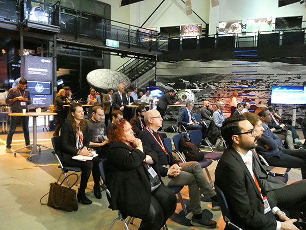
NAVISP Industry Days took place in 2020 at at ESA’s ESTEC, The Netherlands. (Photo: ESA)
The NAVISP Element 1 workplan supports cutting-edge European companies in development of novel PNT technologies and services. Underscoring the commercial priority of this field, 20 ESA Member States plus Canada have joined the program.
PNT underpins a 10th of Europe’s economy, according to ESA, in areas such as transport, precision agriculture, power, communication, banking and the fast-growing internet of things.
Satellite navigation, with signals from space extending across the globe, represents the single biggest source of PNT information, but these signals are not available in all locations and are vulnerable to natural or human-made interference.
NAVISP Element 1 is focused on innovation in PNT, involving novel concepts, techniques, technologies and systems along the entire value chain. They often combine GNSS with other solutions such as artificial intelligence, other sensors, adding Wi-Fi or 5G signals to PNT fixes, or employing high-altitude atmospheric platforms to supplement GNSS coverage over regions in need.
How inertial systems and GNSS availability will help
By Kana Nagai, Matthew Spenko, Ron Henderson and Boris Pervan
Self-driving cars in urban environments can be problematic. The required multi-sensor automated systems will include GNSS, but buildings block and reflect GNSS signals, reducing system availability and accuracy. Researchers from the Illinois Institute of Technology report on how inertial navigation systems coupled with wheel-speed sensors and vehicle dynamic constraints can help.
Innovation Insights with Richard Langley
ARE WE THERE YET? This was a familiar refrain from the backseats of parents’ cars when traveling to a holiday destination or to grandparents when I was growing up. We didn’t have videos on a display attached to the seats in front of us or (who could imagine?) our own personal communication device on which we could call up games, movies or social media channels.
But I’m not talking about that complaint from our childhoods. I’m asking if we have arrived at the era of the self-driving car. The answer is yes and no. It all depends on what you mean by “self-driving.” We reviewed some of the technologies needed for self-driving or autonomous vehicles in this column in June 2019. And we indicated in the introduction to that column that vehicle autonomy has several levels. SAE International, formerly known as the Society of Automotive Engineers, has defined six levels of autonomy that can be briefly described as Level 0 – no automation; Level 1 – hands on/shared control; Level 2 – hands off; Level 3 – eyes off; Level 4 – mind off; and Level 5 – steering wheel optional.
Already, Level 1 automation is widely available in modern cars with adaptive cruise control, parking assistance, lane-keeping assistance and automatic emergency braking among the features being offered.
Level 2 automation, where the automated system takes full control of the vehicle’s acceleration, braking and steering, is available in some production models, although the “hands-off” designation is not to be taken literally — most motor vehicle laws require drivers to keep their hands on the steering wheel.
Between Level 2 and Level 3, we have conditional automation — the car can drive itself, but the driver must stay alert and be prepared to take over immediately.
Level 3 is high automation, where a computer fully drives the car at certain times on certain routes such as a highway; while the driver can perform other tasks such as reading a book, they must be prepared to take over operation of the vehicle within a few seconds if alerted by the automated system. While test campaigns are still ongoing, some jurisdictions permit Level 3 operation by ordinary drivers on some roads, and customers will soon be able to buy vehicles with this level of automation. Widespread use of
Level 4 and Level 5 automation is further off (some would say quite a way off) and remains in development. But famously, last year, Toyota operated Level 4 self-driving shuttle vehicles around the Tokyo 2020 Olympic Village.
A lot more work needs to be done before we will have arrived at the era of the fully self-driving car that will be able to travel on any road, anywhere in the world, all year around, in all weather conditions. In particular, self-driving cars in urban environments (as opposed to highway driving) can be problematic.
The required multi-sensor automated systems will include GNSS, but buildings block and reflect GNSS signals, reducing system availability and accuracy. In “Innovation” this month, researchers from the Illinois Institute of Technology report on how inertial navigation systems coupled with wheel-speed sensors and vehicle dynamic constraints can help.
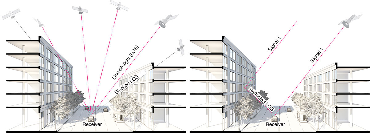
GNSS provides navigation services globally, but satellite visibility in urban areas is limited by high-rise buildings. This creates a mixture of GNSS available and denied environments (see FIGURE 1) — users do not generally know where the system can maintain sufficient levels of accuracy and integrity for a particular application. To begin to address the issue for self-driving cars, we evaluated GNSS-only availability in downtown Chicago.
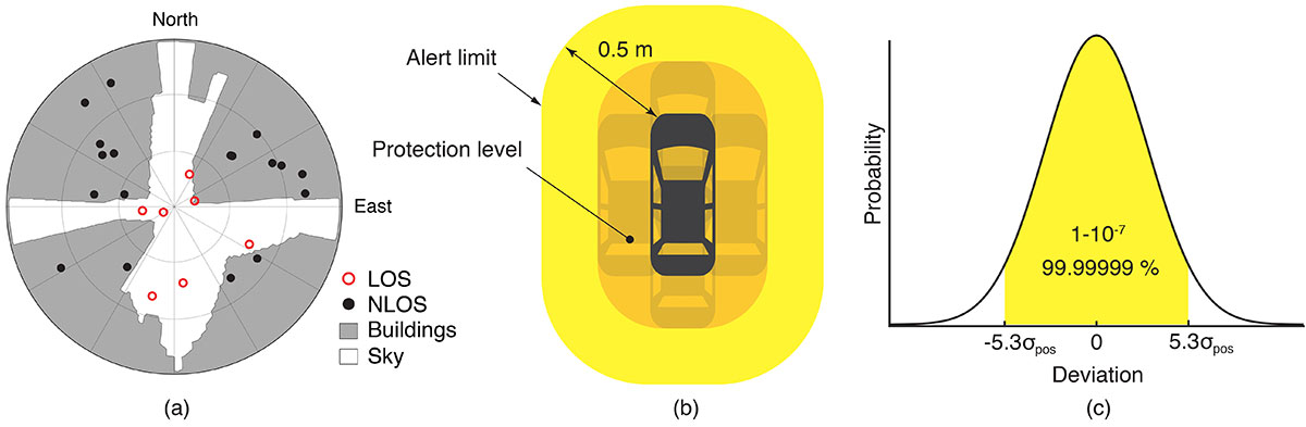
FIGURE 1. The figure depicts three types of potential GNSS signal reception: direct LOS signals and blocked LOS signals (left) and reflected LOS signals (right). (Image: Authors)
GNSS signal prediction in urban environments has been conducted in previous work. For example, the concept of “shadow matching” was developed to identify GNSS signal blockages in urban canyons. Overlaying sky plots on a hemispherical sky view can be used to distinguish between line-of-sight (LOS) and non-line-of-sight (NLOS) signals (see FIGURE 2a). Reflected rays can be predicted using Householder transformations to reveal potential multipath conditions. Satellites producing blocked or reflected (NLOS) signals should be excluded to maintain integrity.
FIGURE 2. (a) A hemispherical sky view in an urban environment. (b) Illustration of a protection level and an alert limit. To ensure integrity, the protection level must not exceed an alert limit. (c) The allowable probability of exceedance is assumed to be 10−7 in this work. (Image: Authors)
When the number of visible satellites is greater than three, GNSS can resolve vehicle position. However, even in cases where enough satellites are visible, the satellite geometries are generally weak because the dilution of precision (DOP) is adversely affected by the buildings partially blocking the sky. Horizontal positioning error must be bounded by a protection level computed by the vehicle. Then, for navigation to be deemed available, the protection level must not exceed a required alert limit (see FIGURE 2b). The maximum allowed probability of exceedance (see FIGURE 2c) and the alert limit can together be used to determine the maximum allowable position error standard deviation.
Even if the protection level is far below the alert limit in an open-sky environment, it will frequently exceed the alert limit once the vehicle enters a city. GNSS alone is generally not able to maintain availability, so integration with other sensors is needed. Tightly coupling inertial navigation systems (INS) with GNSS using the extended Kalman filter (EKF) provides better estimation in urban environments. The EKF algorithm also enables integration of wheel-speed sensors and vehicle dynamic constraints. These integrated navigation systems will improve availability, but it is still unclear how long such a system can be expected to maintain fault-free integrity in a congested city.
Focusing on the problem of self-driving cars in urban environments, we evaluate protection levels of navigation with practical integrated sensors: GNSS, INS, a wheel-speed sensor (WSS) and vehicle dynamic constraints (VDC). The goal is to develop the means by which we can determine locations where external ranging sources (such as lidar) are needed to maintain continuous navigation with fault-free integrity.
GNSS-ONLY AVAILABILITY
For GNSS availability evaluation, we assume an integrity requirement that the probability of exceeding a 0.5-meter alert limit must be lower than 10−7. The 0.5-meter alert limit therefore corresponds to approximately five times the position standard deviation, so the maximum allowable position error standard deviation is then approximately 0.1 meters. Accuracy at this level clearly requires differential GNSS carrier-phase measurements. We assume a nominal GNSS double difference (DD) carrier ranging error standard deviation of approximately 0.02 meters, and that carrier cycle ambiguities can be readily resolved in an open-sky environment prior to initiation of vehicle motion.
Given the assumptions made of the maximum allowable position error standard deviation and the GNSS ranging error standard deviation, the maximum allowable horizontal dilution of precision (HDOP) is about 5.
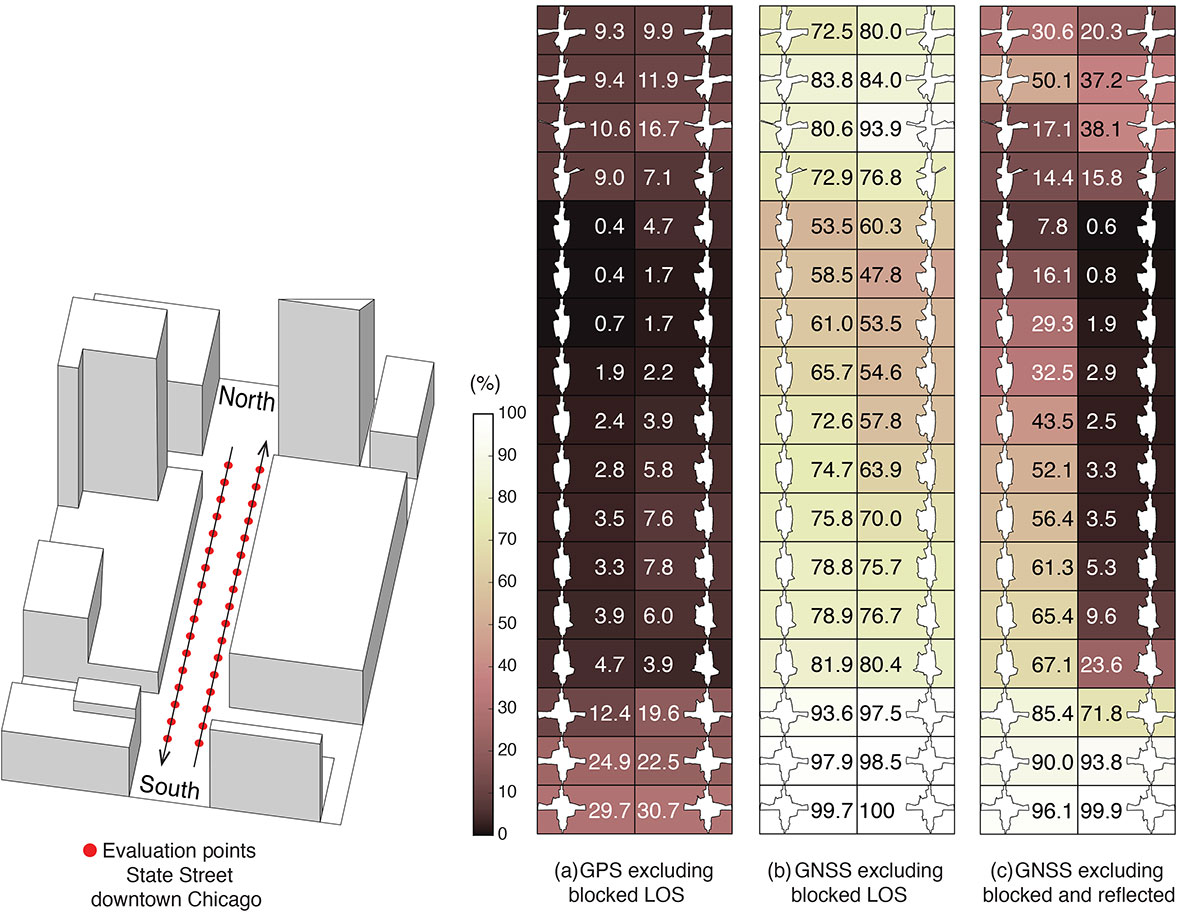
FIGURE 3 shows GPS and GNSS availability — the fraction of time the HDOP requirement is met over 24 hours — along a section of State Street in downtown Chicago. The availability results using GPS only and excluding only blocked LOS signals ranged from 0% to 9% along the block and 9% to 30% at the intersections (see FIGURE 3a). Using four full GNSS constellations (GPS, Galileo, GLONASS and BeiDou), availability ranged from 48% to 82% along the block and 72% to 100% at the intersections (see FIGURE 3b).
FIGURE 3. The percentage of GPS or GNSS availability in 3D-mapped downtown Chicago. We exclude satellites producing blocked LOS signals or both blocked and reflected LOS (NLOS) signals from the measurements. Each column expresses a lane of southbound or northbound travel. The availability is the percentage of total time when HDOP meets the self-driving car integrity requirements in 24 hours. (Image: Authors)
When we also excluded satellites producing reflected LOS signals that reach the vehicle, the availability dropped significantly at every point (see FIGURE 3c). We assert that FIGURE 3c expresses the reality of GNSS availability because building-reflected multipath signals degrade positioning accuracy and would affect integrity negatively. It’s obvious from these results that GNSS alone is insufficient to meet the autonomous driving requirements in an urban environment, and multi-sensor integrated navigation systems are needed to augment poor GNSS signal availability.
MULTI-SENSOR INTEGRATION
We begin by considering tightly coupled INS/GNSS integration using an EKF, and then integrate a realistic sensor suite including WSS and vehicle dynamic constraints that enforce resistance to lateral sliding and vertical movement. If it is known from another source that the vehicle is not moving (for example, it is in the parking gear), a static mode constraint (SMC) can also be applied.
INS/GNSS Integration. Tightly coupled INS/GNSS integration with an EKF uses the INS measurement to predict vehicle motion. The continuous process model uses a state vector having the position in the navigation frame, the velocity, the attitude, bias errors and cycle ambiguities, with the input vector having accelerometer-specific force measurement in the body frame and gyro-rotation-rate measurements. A white-noise vector drives the inertial measurement unit (IMU) states.
The GPS/GNSS measurement model includes the measurement vector having carrier and code phases, and the observation matrix containing LOS vectors and the vector of white receiver thermal noise.
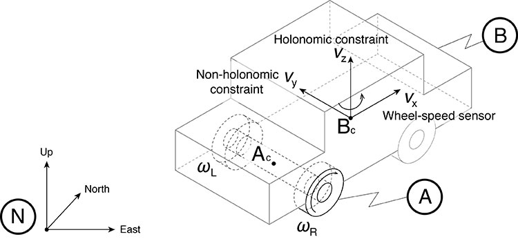
INS/GNSS/WSS/VDC Integration. For the vehicle in motion, we developed a model consisting of a WSS measurement in the along-track direction, a non-holonomic constraint resisting lateral sliding, and a holonomic constraint on vertical movement (see FIGURE 4).
The INS/GNSS/WSS/VDC integration using the EKF consists of the process model and the measurement models.
FIGURE 4. The measurement model consisting of the WSS measurement in the along-track direction (vx), non-holonomic constraint resisting lateral sliding (vy), and holonomic constraint on vertical movement (vz). N is the navigation frame, Ac is the rear-axle center point and Bc is the center point of the body-fixed frame. (Image: Authors)
INS/GNSS/SMC Integration. The static mode constraint provides zero-velocity measurements to the EKF measurement update to mitigate position error propagation. We use SMC only when it is known that the vehicle is not moving; for example, when the vehicle is in the parking gear.
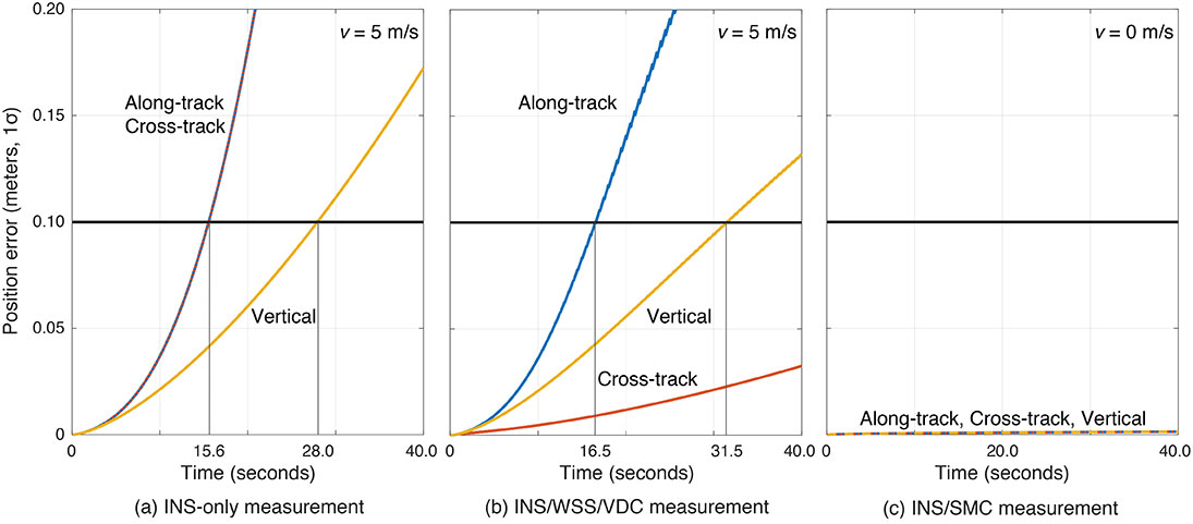
Error Propagation Analysis. We tested the time from perfect initialization to when position error exceeds 0.1 meters in GNSS-denied environments. FIGURE 5 shows the error growth in the along-track (x), the cross-track (y) and the vertical (z). The error specifications for a STIM300 tactical-grade IMU are used in this analysis. The standard deviation of the WSS measurement noise is assumed to be 0.05 meters per second, and the standard deviation of the movement constraint violations is 0.001 meters per second. The vehicle is moving at 5 meters per second except when we test the SMC.
The INS can coast 15.6 seconds before the position error standard deviation exceeds 0.1 meters in both the along-track and the cross-track directions (see FIGURE 5a). The INS/WSS/VDC can coast 16.5 seconds in the along-track direction, and significantly more than 40 seconds (the simulation duration) in the cross-track direction (see FIGURE 5b). In static mode, INS/SMC estimate errors do not grow with time in any direction, as expected (see FIGURE 5c). In GNSS-denied environments, the non-holonomic constraint suppresses the cross-track position error, but the WSS measurement hardly affects the along-track position error. The SMC works perfectly, but the usage is limited to when the vehicle is known to be stationary.
FIGURE 5. The vehicle position error growth vs. time in the along-track (x), cross-track (y) and vertical (z) directions. Each graph represents the navigation system introduced in the multi-sensor integration section. The vehicle is moving at 5 meters per second (a and b) or 0 meters per second (c). (Image: Authors)
SIMULATION SCENARIO
We imagine a future driverless-car mission scenario in which multi-sensor navigation systems are practicable. To minimize congestion in a city, autonomous vehicles will be held outside the urban core when not in use. In the clear open-sky environment, a vehicle in a parking lot completes GNSS initialization using the INS/GNSS/SMC system. Once requested for action, the vehicle departs for the city from the parking lot, and the motion of the vehicle improves alignment by the INS/GNSS system. Safe navigation can be ensured using the system to provide continuity under overpasses and bridges in the open-sky environment. Upon entering the urban core, navigation becomes more dependent on the INS/WSS/VDC system.
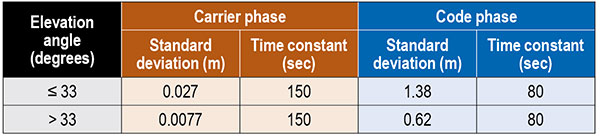
A reasonable numerical target for differential GNSS initialized position error is 0.02 meters, and for the INS alignment yaw angle error 0.1 degrees.
Local GNSS multipath errors from nearby vehicles will vary with the satellite elevation angle. Prior experimental results show that lower elevation-angle satellite signals (below 33 degrees) are much more likely to be impacted by multipath than higher ones (see TABLE 1).
Table 1. The nominal GNSS multipath error values in the simulation.
INITIALIZATION AND ALIGNMENT
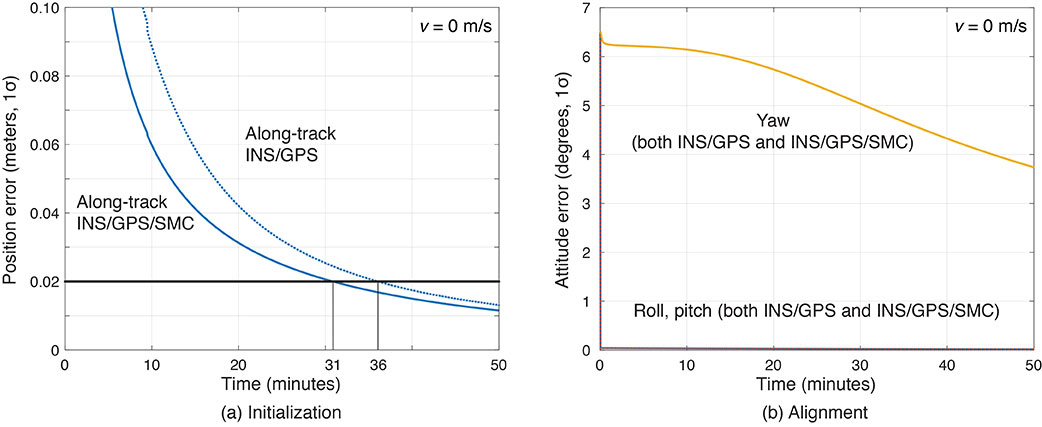
Initialization takes place in a parking lot with a clear sky view. A vehicle is in the parking gear, enabling SMC to be applied. FIGURE 6a shows a typical example: with INS/GPS/SMC, system initialization takes about 31 minutes, and with INS/GPS, about 36 minutes. Therefore, SMC does speed up GPS initialization, although the improvement is modest.
The yaw angle is not aligned during the initialization, but roll and pitch are immediately aligned (see FIGURE 6b). Earth’s gravity affects roll and pitch angle alignment but not yaw angle.
Yaw angle alignment cannot be performed when the vehicle is stationary or moving with constant velocity. Accelerated motion, either straight or turning, is required.
FIGURE 6. (a) Comparisons of initialization time between INS/GPS and INS/GPS/SMC in an open-sky environment. The INS/GPS/SMC system initializes rapidly. (b) Transitions of roll, pitch, yaw alignment during the initialization. Yaw angle alignment cannot be performed when the vehicle is stationary. (Image: Authors)
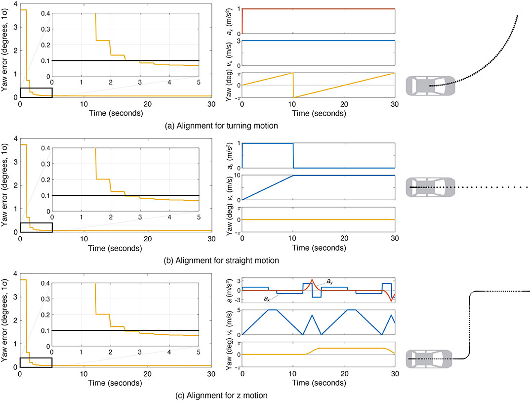
FIGURE 7 shows the behavior of the yaw angle error standard deviation using the INS/GPS system when centripetal (see FIGURE 7a) or tangential (see FIGURE 7b) acceleration is applied. The yaw angle can be aligned in a couple of seconds for either type of acceleration. To represent typical initial motions of self-driving cars, we model a parking-lot departure via a “Z”-shaped path. In this scenario, the yaw alignment error reaches 0.1 degrees within a couple of seconds (see FIGURE 7c).
FIGURE 7. The behavior of yaw angle error when centripetal (a) or tangential (b) acceleration is applied; (c) shows the behavior while following a z-shaped path. The yaw angle can be aligned in a couple of seconds in each case. (Image: Authors)
EVALUATION IN URBAN ENVIRONMENTS
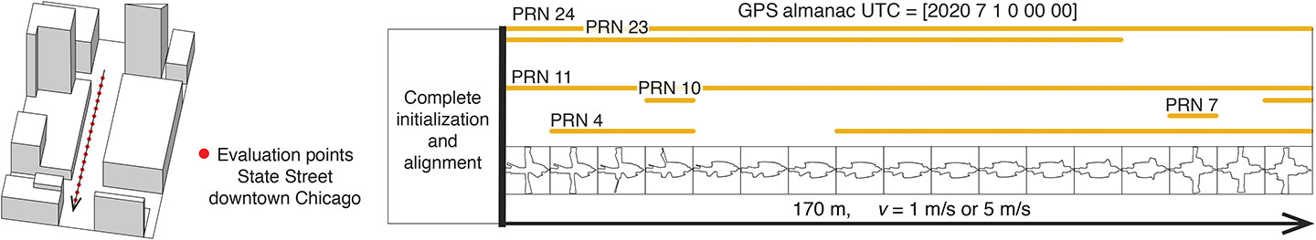
After initialization and alignment in the open-sky environment, we simulated the vehicle traveling into the urban core. The urban environment in our study is 3D-mapped State Street in Chicago, which runs north-south and transits from low-rise neighborhoods to central downtown. We selected one congested section surrounded by tall buildings and computed the position error standard deviation along the path. The evaluation points are at 10-meter intervals over a total distance of 170 meters. The yellow lines in FIGURE 8 denote the visible satellites, identified by their pseudorandom noise (PRN) code numbers, at each point. We assume for convenience that the INS/GPS system is initialized and aligned at the first evaluation point. In reality, we would expect a degraded initial condition because we are starting the simulation in an urban canyon.
FIGURE 8. Evaluation points and PRN numbers of visible satellites at each point. (Image: Authors)
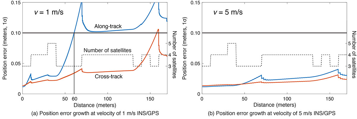
In the first simulation, the car equipped with the INS/GPS system moved either 1 or 5 meters per second. The y-axis in FIGURE 9 represents the position error standard deviation, and the x-axis represents the distance in meters. The dotted line expresses the number of visible satellites. The error when the vehicle velocity is 1 meter per second exceeded the maximum allowable position error standard deviation of 0.1 meter, at the distance of 60 meters. However, when the velocity was 5 meters per second, the maximum allowable position error standard deviation was never reached. It is also clear from the figures that error propagation is significantly affected by the number of visible satellites.
FIGURE 9. A comparison of position error growth between velocities of 1 meter per second and 5 meters per second. (Image: Authors)
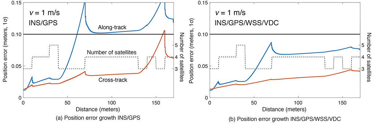
In the second simulation, we compared two different navigation systems, INS/GPS and INS/GPS/WSS/VDC. The vehicle moved at 1 meter per second in the same urban environment. The INS/GPS/WSS/VDC system does provide relief, but the error propagation is still clearly affected by the number of visible satellites (see FIGURE 10).
FIGURE 10. A comparison of position error growth between the INS/GPS and INS/GPS/WSS/VDC systems for a velocity of 1 meter per second. (Image: Authors)
In GNSS-challenged environments, INS error propagation is a function of time. When a vehicle moves faster, it clears the blockage area more quickly, reducing the impact of INS drift — a function of time, not distance. In contrast, GNSS error is completely determined by location. Because INS error propagation depends on how long the vehicle stays in an area of GNSS outage, protection levels for trips through the same area will be different if the vehicle is smoothly cruising or gets stuck in a traffic jam.
CONCLUSION
To gain a better understanding of how long and under what local conditions multi-sensor integrated navigation systems can maintain fault-free integrity, we evaluated navigation positioning errors in 3D-mapped downtown Chicago. The system we developed consists of sensors with which self-driving cars would reasonably be equipped: GNSS, INS, WSS and dynamic constraints. We showed that INS/GPS position errors along the path depend very strongly on the vehicle’s speed. When the system is augmented with WSS/VDC, position errors are suppressed, but the error propagation is still strongly influenced by the number of visible satellites.
ACKNOWLEDGMENTS
The research described in this article is supported by the National Science Foundation. Figure 1 was created by Alexis Arias of the Landscape Architecture + Urbanism Program at the Illinois Institute of Technology (IIT). The authors greatly appreciate the advice and help of Nilay Mistry from that program.
This article is based on the paper “Evaluating INS/GNSS Availability for Self-Driving Cars in Urban Environments” presented at ION ITM 2021, the virtual 2021 International Technical Meeting of The Institute of Navigation, Jan. 25–28, 2021.
KANA NAGAI is a Ph.D. candidate and research assistant in mechanical and aerospace engineering at IIT.
MATTHEW SPENKO is a professor of mechanical and aerospace engineering at IIT. He earned his M.S. and Ph.D. degrees in mechanical engineering from the Massachusetts Institute of Technology.
RON HENDERSON is a professor and director of the Landscape Architecture + Urbanism Program at IIT. He earned his Master of Landscape Architecture and Master of Architecture from the University of Pennsylvania.
BORIS PERVAN is a professor of mechanical and aerospace engineering at IIT. He earned his M.S. from the California Institute of Technology and Ph.D. from Stanford University.
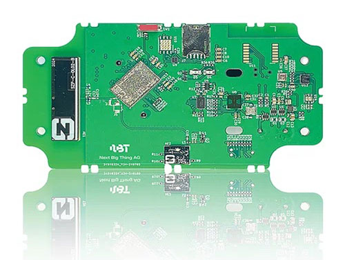
German venture studio Next Big Thing AG (NBT) has launched the Prometheus internet of things (IoT) sensor-based development platform designed to simplify prototyping and speed time-to-market for developers of cellular IoT- and cloud-based solutions.
The Prometheus platform is powered by Nordic Semiconductor’s nRF9160 low-power system-in-package (SiP) with integrated LTE-M/NB-IoT modem and GNSS. The platform supports development across a wide range of industrial applications including the manufacturing, pharmaceutical and logistics sectors.
The nRF9160 SiP’s 64-MHz Arm Cortex-M33 dedicated application processor provides sufficient computational power to not only supervise the LTE-M/NB-IoT modem’s cellular connectivity, but also all other product functionality. The SiP’s 1MB Flash and 256kB RAM supports fast response and complex application software.
In addition to the Nordic SiP, the CE-certified development platform features a wide range of sensors and interfaces, a stable embedded software stack, fully encrypted communication, mesh connectivity for short-range communication, automatic switching between NB-IoT and LTE-M cellular IoT connectivity, and advanced provisioning tools. The solution is optimized for low power consumption and provides an industrial temperature range of –40 to +85° C.
NBT’s IoT development platform comprises two main components:
the hardware and embedded software platform (Prometheus)
the cloud-based software platform (NBT software platform).
The standard configuration of Prometheus consists of a range of sensors, for example a temperature sensor (analog and digital), accelerometer, magnetometer, gyroscope, air quality sensor, ambient light sensor and humidity sensor.
The extended version of Prometheus also includes Nordic’s nRF52832 Bluetooth 5.2/Bluetooth Low Energy (Bluetooth LE) general purpose multiprotocol system-on-chip (SoC) to provide support for Bluetooth LE connectivity, as well as USB, GPS, radar, an adjustable antenna tuner and extended temperature range.
For navigation and control of any robotic or autonomous outdoor system, GNSS and inertial navigation systems (INS) are key components. Inevitably, the question arises: Should you build your own custom solution or integrate an available GNSS/INS combined solution? What would give you the best performance, while keeping the total cost of ownership (TCO) to a minimum? The TCO is also known as the “long-term price” and is defined as the purchase price plus the costs of operation over time.
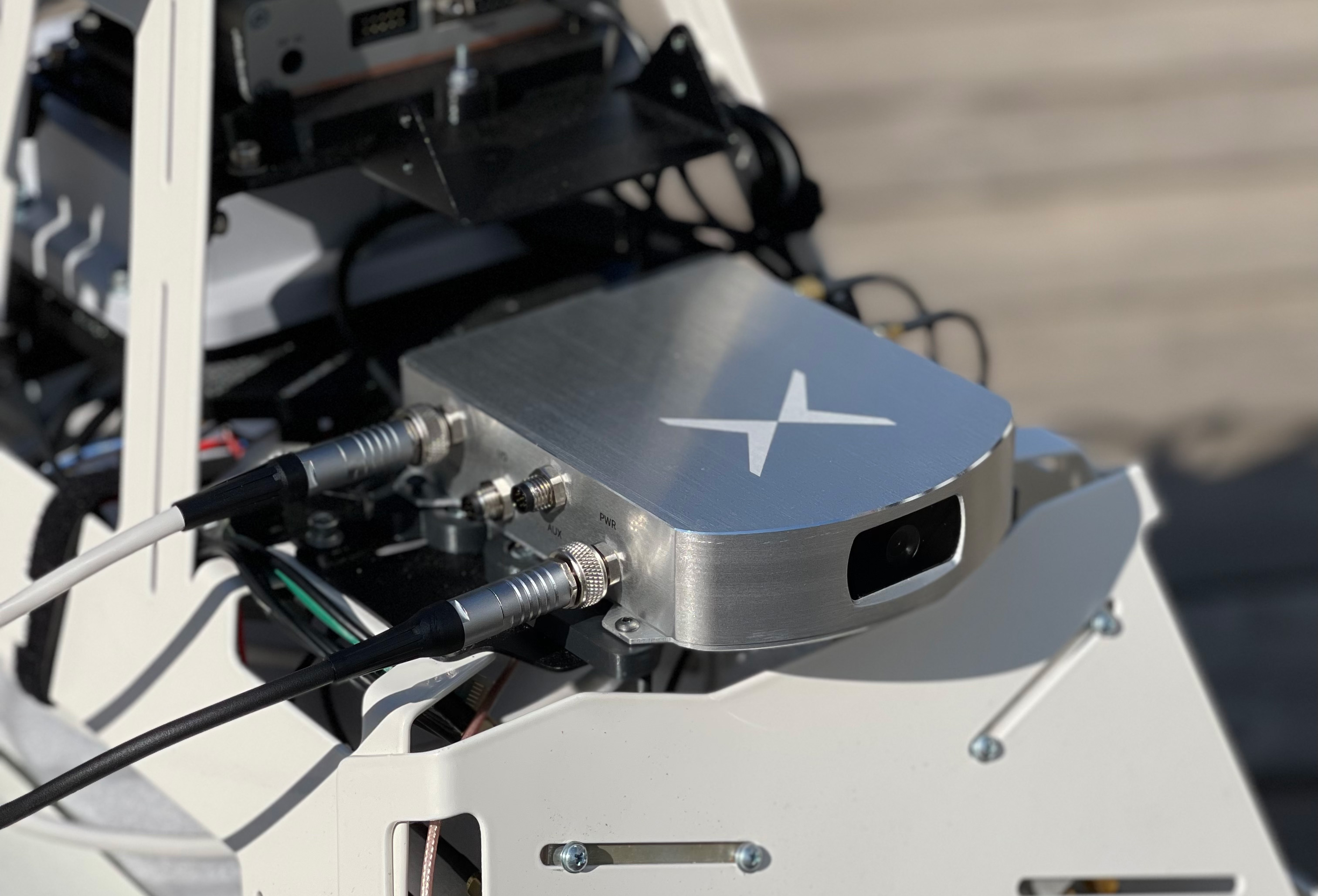
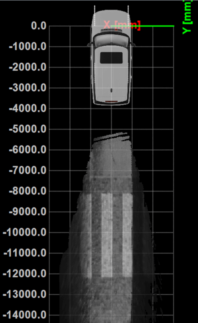
Xenomatix is a company offering automotive solutions based on lidar technology. With eight years of innovative experience, Xenomatix has installed a pre-integrated GNSS/INS receiver on its latest lidar product, achieving high GNSS/INS performance with minimal TCO.
In an integrated INS/GNSS receiver, the GNSS receiver provides positioning with centimeter-level accuracy. The other component is a micro-electromechanical inertial measurement unit (MEMS IMU), which measures 3D orientation in terms of heading, pitch and roll angles with sub-degree precision. For its latest product XenoTrack, Xenomatix chose an INS called XenoAsterx based on the AsteRx SBi3 from Septentrio, which it integrated alongside its lidar to collect road-quality data to the smallest detail.
From an in-house solution to a pre-integrated system
Three years ago, when Xenomatix started developing its new lidar road-inspection system, the company had a GPS receiver, an IMU and an odometer as accompanying sensors. The company wanted to expand into new markets of road inspection in accordance with international standards, and so it needed to improve its components to take the overall performance of its system to the next level with RTK high-accuracy positioning.
To achieve this, while saving time and costs, Xenomatix acquired an AsteRx SBi3 INS/GNSS receiver, which allowed it to focus on its core lidar technology and sensor-fusion algorithms.
This off-the-shelf INS/GNSS solution provided all the high-accuracy positioning and orientation information Xenomatix needed, while eliminating most costs of development, maintenance and support. The new receiver allowed them to drive for miles, without any offset in positioning, something impossible with the previous GPS receiver.
The unique technology from Xenomatix stitches images by using lidar point-cloud overlays. However, when the car is moving fast, this overlay is smaller. The pre-calibrated GNSS/INS extends system performance by allowing stitching even when driving at higher speeds.
“If we start driving and we stitch the road for tens of kilometers and we come back to the same starting point, then we see an offset of only a few millimeters,” said Filip Geuens, CEO, Xenomatix. “This is for us the strongest proof of accuracy and reliability of the GNSS sensor.“
Why pre-integrated GNSS/INS offers better value
The pre-integrated GNSS/INS allows XenoTrack to collect road data even at higher speeds. (Credit: Septentrio)
A pre-integrated GNSS/INS solution — versatile enough to fit into virtually any autonomous or mapping system — offers the best value in the long run for the following reasons.
Better performance. The manufacturer of a GNSS/INS solution specializes in fusing the GNSS receiver and the INS in an optimal way. To accomplish this, the sensors are synchronized and their output run through a sophisticated Kalman filter algorithm. The fused device is then fine-tuned for optimal operation under various conditions. Finally, it is extensively tested and validated.
While being used by numerous customers and in varying applications, the GNSS/INS solution proves itself on various levels such as accuracy and robustness. This results in superior performance, even in the most demanding environments.
After installing the AsteRx SBi3 GNSS/INS system, XenoTrack was able to extend its functionality to inspect longer distances of roads at higher speeds. The AsteRx SBi3 operates reliably, even in challenging environments, such as when driving near high cliffs or under bridges.
Less development time and lower costs. When building a system, the development time is usually about one year employing two full-time GNSS/INS specialists. Hardware components need to be integrated and synchronized, while various interfaces and the Kalman filter need to be implemented. Additional features may be developed, such as velocity input as well as tools for validation, before the intricate step of performance fine-tuning. Finally, additional testing efforts are needed for verification and validation of the device.
On the other hand, a pre-integrated GNSS/INS system with easily accessible interfaces and flexible configuration ensures quick installation, meaning the product is ready within weeks.
Lower maintenance costs and support. Certain high quality pre-integrated GNSS/INS receivers are future-proof — ready to use new GNSS satellite signals and services as soon as they become available. An example of such upcoming service is the Galileo OSNMA anti-spoofing authentication.
Some receiver manufacturers such as Septentrio also offer continuous product improvement in the form of free firmware updates. A system developed in-house, on the other hand, needs continuous investment to maintain its competitive edge.
When issues occur, Septentrio also offers local worldwide support, with experienced application engineers ready to solve GNSS, INS or coupling issues that could halt the production process. For example, when Xenomatix discovered that its GNSS/INS was not working optimally in a certain environment, the company called Septentrio. Within days application engineering experts who analyzed the logged data found the source of the issue and proposed a solution.
Focus on core technology. When the budget is limited, choices need to be made about where to focus the efforts. When a company saves on GNSS/INS development, more can be invested in core technology. This means avoiding any lost-opportunity costs and optimizing margins.
Building your own is not always the best option
Acquiring a pre-integrated GNSS/INS receiver allowed Xenomatix to have a superior and affordable product with a competitive edge. AsteRx SBi3 increased the performance of the XenoTrack mapping system, while a short integration period allowed a faster time-to-market.
Xenomatix also benefited from low maintenance costs, keeping overall TCO to a minimum. Since the company was not spending time developing a custom GNSS/INS system, it could focus fully on its core technology. This allowed Xenomatix to take its business to the next level at a high pace.
Award-winning technology
In November 2021, the XenoTrack road scanner, with AsteRx SBi3 inside, was announced a winner of the IRF Global Road Achievement Award for its innovative road scanning and surveying solutions.
An Oculii sensor placed at the front corner of a vehicle. (Photo: Oculii)
Oculii’s patented adaptive AI software increases resolution of existing RF radar silicon up to 100X
Ambarella Inc. has entered into a definitive agreement to acquire Ohio-based Oculii Corp. Oculii’s adaptive artificial intelligence (AI) software algorithms are designed to enable radar perception using current production radar chips to achieve significantly higher (up to 100x) resolution, longer range and greater accuracy.
The fusion of Ambarella’s camera technology and Oculii’s radar software stack provides an all-weather, low-cost and scalable perception solution, enabling higher levels of autonomy for Tier 1 automakers and OEMs globally.
Oculii’s technology eliminates the need for specialized high-resolution radar chips, which have significantly higher power consumption and cost than conventional radar solutions. Oculii’s software can be deployed on Ambarella’s existing CVflow systems-on-chip (SoCs), operating in conjunction with radar RF solutions to increase safety and reliability.
The acquisition expands Ambarella’s addressable market into radar perception and fusion with its existing SoCs for automotive and other internet of things endpoint applications, including mobile robotics and security.
Oculii’s superior resolution and sensitivity can unlock the potential of everything from advanced driver-assistance systems (ADAS) and autonomous vehicles to robotics and security, by providing radar with a dynamic waveform that uses AI to learn from and adapt to the environment. The result is an extended operating range of up to 400 meters with a wide field of view.
To date, Oculii is engaged with 10 of the top 15 Tier 1s on software licensing, and has commercial development contracts with other OEM and AV companies. Oculii is generating pre-production revenue today, with production programs expected to commence in CY2023.
The boards of directors at both companies have approved the transaction, which is subject to customary closing conditions and expected to close during Ambarella’s Q4 FY2022 (ending January 31, 2022). Wilson Sonsini Goodrich & Rosati served as legal advisor to Ambarella, and Goodwin Procter served as legal advisor to Oculii. Greenhill & Co. served as financial advisor to Ambarella.
A new European project is researching automated collection of geodata and production of high-definition maps.
The GAMMS project is funded by the European Union Agency for the Space Programme (EUSPA), and will take place until the end of 2023. Galileo will be the main enabler of GAMMS, given its precise, multipath-resistant measurements and its upcoming high-accuracy service (HAS).
A European consortium, led by the French map service provider GEOSAT, will investigate how the combination of self-driving mapping cars (autonomous mobile-mapping systems) and artificial intelligence-based mapping software can automate the production of high-definition maps.
These maps are used by driverless vehicles and need to be provably accurate, complete and up to date. Fast, sustainable production of trustworthy maps is the goal.
Consortium members include:
GEOSAT — map-making and machine learning
GeoNumerics — multi-sensor fusion and accurate navigation
“It is as challenging as interesting to bring together the geodetic estimation methods with the navigation ones in multi-sensor systems powered by EGNSS and its differentiators, VDMs (vehicle data management systems) and visual features,” said Marta Blázquez, responsible for GAMMS at GeoNumerics. “GAMMS will boost the development of NEXA, our trajectory determination platform, and GENA, our adjustment platform for dynamic networks, in the direction of trustworthy navigation.”
GeoNumerics is responsible for computing the mapping vehicle trajectory (a time series of position, velocity and attitude coordinates) by integrating the manifold of sensors available in a mapping vehicle.
Measurements of inertial units and atomic clocks will be fused with measurements of all available navigation satellites (GPS, GLONASS, Galileo and BeiDou), odometers, cameras and laser scanners. For this purpose, GeoNumerics’ GENA and NEXA systems will be further developed to include new sensor mathematical models and to improve its robust estimation methods.