On Aug. 19, the U.S. Federal Communications Commission (FCC) granted a request for authorization from AT&T Services to use Galileo for emergency location purposes.
AT&T plans to use Galileo in conjunction with GPS to improve the accuracy of its E9-1-1 location services on mobile devices, and facilitate faster response from emergency services when wireless callers dial 9-1-1.
The request was approved by the FCC’s Public Safety and Homeland Security Bureau .
The FCC found that AT&T had satisfied the conditions for commercial mobile radio service (CMRS) providers to integrate foreign satellite signals into E9-1-1 services.
Under E9-1-1 requirements established in 2015, CMRS providers seeking to use foreign signals for E9-1-1 services must meet several conditions, including ensuring that integrating non-U.S. signals won’t cause interference with the E9-1-1 system.
Carriers also need to submit a signal integration plan including a mechanism to detect, mitigate and disable Galileo signals if they cause harmful interference.
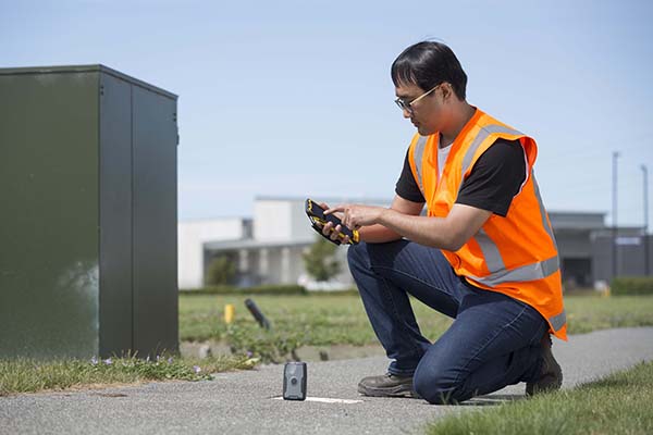
TDC’s Freeance field applications leverages Trimble GNSS for accurate, streamlined data collection
TDC Group has joined Trimble’s GIS (geographic information system) Business Partner Program. As part of the program, TDC has implemented the Trimble Precision SDK (software developer kit) to integrate high-accuracy positioning capabilities in its Freeance mobile software applications running on tablets and smartphones using Trimble GNSS receivers.
Freeance provides field crews with simple yet powerful and configurable location-based mobile apps to manage data collection and inspection activities across utility and public works organizations. By adding the Trimble R1 and R2 receivers to Freeance workflows, users are empowered with real-time access to high-quality, reliable data.
The Trimble R1 receiver will be accessible with TDC’s Freeance software. (Photo: Trimble)
“Trimble recognizes the value our GIS software partners bring to our customers by delivering targeted, industry-specific solutions,” said Stephanie Michaud, strategic marketing manager, Trimble Survey & Mapping Field Solutions. “We’re very pleased to collaborate with TDC and leverage their domain expertise, and to integrate Trimble technology into the Freeance solution for the utilities and public works markets. As a direct result of this relationship, Freeance users can now work with the confidence of knowing their field workflows are precision-enabled with Trimble GIS technology.”
“We’re excited about the integration of high-accuracy Trimble GNSS receivers with Freeance software that enables organizations to add sub-meter or better accuracy to mobile workflow activities using smartphones and tablets,” said Matthew Reddington, CEO of TDC Group. “Adding high-accuracy positioning to field workflows by means of simple mobile apps paired with Trimble GNSS increases the quality and uses of data captured during field operations.”
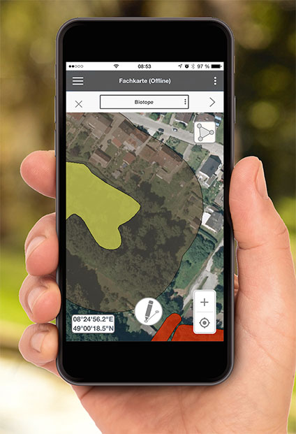
The European GNSS Agency, based in Prague, is providing on its website a list of location-enabled applications that it considers potentially useful in response to the COVID-19 pandemic.
The applications range from those helping public authorities understand the dynamics of the outbreak to supporting citizens in their everyday lives by checking supermarket lines.
The apps are sorted into four categories:
Tracking the COVID-19 pandemic
Queue management
Response management
Information dissemination
If you are an application developer and you want to add your app to the list, contact [email protected].
In moves sure to concern privacy advocates, 19 countries are now accessing citizens’ mobile location data in an effort to fight the coronavirus outbreak.
A COVID-19 Digital Rights Tracker by Top10VPN lists countries that are using mobile data for the pandemic. Uses range from anonymous aggregated data to monitor the general movement of people, to tracking the phones of individual coronavirus patients, to tracking suspected patients and their contacts, known as “contact tracing.”
“In the past week we have witnessed a 90% growth in the number of countries implementing digital tracking measures and a 100% increase in reports of censorship,” reported Top10VPN on March 26.
In the United States, the Senate’s $2 trillion economic stimulus bill includes $500 million for the Centers for Disease Control (CDC) to launch a new “surveillance and data-collection system” to monitor the spread of COVID-19, reports Business Insider.
Europe’s telecom companies are sharing location data with health authorities in Italy, Germany and Austria, according to Reuters, to check whether people are remaining at home. The data is aggregated and anonymous, mapping concentrations rather than individuals to respect Europe’s privacy laws.
In South Korea, the government created a map of cellphone data provided by telecom and credit card companies. The map was made public so everyone could track whether they’d been exposed, according to The Verge.
According to reports, Iran used the COVID-19 epidemic to gather private data from its citizens “to boost Tehran’s surveillance capabilities,” reports Vice. The country sent a link to download the AC19 app with government endorsement, touting it as a way to determine whether users have the virus, but usage required sending back location data.
In Taiwan, a mobile phone-based geo-fence uses location-tracking to ensure people who are quarantined stay in their homes, reports the New York Times. If the patient leaves their home address or turns off their smartphone, the police will visit within 15 minutes.
SafePaths app
The new Private Kit: SafePaths app, developed by Massachusetts Institute of Technology (MIT) researchers, is now available, though it is still under development. The downloadable app (for IOS and Android 8.0 and above) informs users if they’ve crossed paths with coronavirus patients, known through published data.
“The solution is a ‘pull’ model where users can download encrypted location information about carriers so the users can self-determine their likely exposure to COVID-19 and coordinate their response with their doctor using their symptoms and personal health history,” according to a white paper about the contact-tracing app.
The app takes privacy into consideration — COVID-19 patients consent to provide health officials with an accurate location trail once they are diagnosed. “Governments are equipped with a tool to redact location trails and thus broadcast location information with privacy protection for diagnosed carriers and local businesses,” the white paper reads.
“Since the outbreak of COVID-19, governments around the world have implemented a range of digital tracking, physical surveillance and censorship measures in a bid to slow the spread of the virus,” warns Top10VPN. “Some of these may well be proportionate, necessary and legitimate during these unprecedented times. However, others have been rushed through legislative bodies and implemented without adequate scrutiny.”
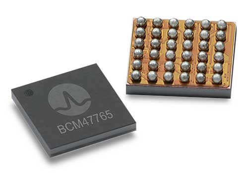
BCM4776 chip utilizes 30 new L5 signals to deliver higher navigational accuracy and yield
Photo: Broadcom
Broadcom introduced in 2017 the first mass-market implementation of dual frequency: BCM4775. This chip makes use not only of the classic L1 frequency broadcast by every satellite, but also of the more advanced L5 signal broadcast by a subset of the satellites.
The use of this enhanced L5 signal improves the accuracy of GNSS in an urban scenario, as it mitigates the main source of error: the reflections in the nearby buildings, also known as multipath. It also improves GNSS in an open-sky scenario, allowing submeter accuracy, a previously unmet performance bar in smartphones until now. Ever since, the BCM4775 has been adopted in flagship smartphones, smartwatches and fitness devices.
Given the unabated need for better precision and accuracy, Broadcom has introduced its second-generation dual-frequency GNSS solution — the BCM4776.
The new chip is capable of using the new BeiDou-3 constellation’s B2a signals (the Chinese indicator for L5). It will be able to track 30 new L5 signals (60 percent more) with a significant impact on accuracy. End users will experience much higher reliability of the submeter accuracy inherent to dual-frequency L1-L5.
Image: Broadcom
Second generation dual-frequency GNSS will be used for innovative lane-level driving navigation instructions, allowing driving applications to know which highway lane the vehicle is in. Expect instructions like “move one lane to the right so you don’t miss your next highway exit” or “move one lane to the left to take the pool lane and save 10 minutes.”
Global mobile wireless standards body 3GPP has given its approval to the regional navigation system created by the Indian Space Research Organization (ISRO), known as NaVIC, reports The Times of India.
The approval was given for the system’s use in Rel-16 LTE and Rel-17 5G NR specifications, paving the way for wider commercial adoption of NaVIC and allowing it to be integrated with 4G, 5G and internet of things technology (IoT).
Once these specifications are adopted by Telecommunications Standards Development Society, India (TSDSI), IoT devices in India can make a switch from GPS to NaVIC.
Electronics companies can start designing and building integrated circuits and mass manufacture other products created to be compatible with NaVIC.
The estimated number of Galileo-enabled smartphones in use has reached one billion. This significant milestone has been achieved in the week when the European GNSS Agency (GSA), responsible for operation of the Galileo programme, celebrates its 15th anniversary.
The company BQ pioneered Galileo use in smartphones with its Aquaris X5 Plus in July 2016. Since then, market uptake of Galileo-enabled smartphones has been rapid as other manufacturers were quick to embrace the opportunities that Galileo offers.
Global annual GNSS receiver shipments are forecast to grow from 1.8 billion units in 2019 to 2.7 billion units in 2029.
Currently, 156 Galileo-enabled smartphone models available on the market. The “1 billion users” milestone is based on the number of smartphones using Galileo sold across the world. The actual number of Galileo users around the world is much larger. You can track which devices, including smartphones, are Galileo-enabled on the UseGalileo.eu site.
Today, 95% of companies that produce smartphone chips for satellite navigation make chips that enable Galileo. According to figures in the latest GSA GNSS Market Report, which is to be published soon, global annual GNSS receiver shipments are forecast to grow continuously across the next decade, from 1.8 billion units in 2019 to 2.7 billion units in 2029. Most of these shipments are for receivers costing less than €5, and 90% of receivers in this price segment are used in smartphones and wearables.
The number of Galileo-enabled smartphones in use has soared to 1 billion in just 3 years. (Image: GSA)
“Galileo is now providing high quality timing and navigation services to 1 billion smartphone users globally,” said Elżbieta Bieńkowska, commissioner for Internal Market, Industry, Entrepreneurship and SMEs. “This has been made possible by a truly European effort to build the most accurate navigation system in the world, with the support and dedication of the GSA. I am confident that our space industry will continue to thrive with more work, ideas and investment under the new EU Space Programme.”
“One billion smartphone users is a significant milestone and a major achievement for the Galileo programme and for the GSA,” said GSA Executive Director Carlo des Dorides. “The GSA has worked tirelessly to build bridges with research and industry and create a strong community of service providers who trust Galileo and understand the technological innovation opportunities it brings.
“Chipset and receiver manufacturers in particular have been quick to leverage Galileo’s outstanding performance,” des Dorides said. “These manufacturers believed in Galileo from the beginning, when Galileo was still an idea, and invested in the technology. It is thanks to them and the unique blend of expertise and knowledge of the GSA team that we are now celebrating 1 billion Galileo-enabled smartphones.”
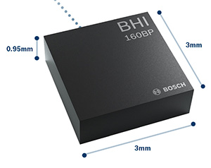
The BHI160BP position tracking smart sensor. (Photo: Bosch Sensortec)
Bosch Sensortec has released the BHI160BP, a position tracking smart sensor that uses integrated inertial sensors to improve GPS location tracking.
Bosch will exhibit the new sensor at Electronica Munich, Nov. 13-16.
When used with a GPS or GNSS module, the BHI160BP enables users to take full advantage of pedestrian position tracking with up to 80 percent saving in system power consumption compared with a typical GNSS-only solution, without compromising on accuracy, the company said.
Users benefit from greatly extended battery life and longer charging intervals for wearable applications such as smartwatches and fitness trackers as well as mobile devices such as smartphones.
The new position tracking approach is set to enable a new class of compact devices with even smaller batteries, Bosch claimed.
The BHI160BP tracks a person’s position by intelligently applying an inertial-sensor-based algorithm for pedestrian dead reckoning. To maintain accuracy, it calculates the user’s relative location based on data collected from the inertial sensors and then recalibrates itself every few minutes to obtain the absolute position provided by the GNSS/GPS module. This means that the GNSS/GPS module can be kept in sleep mode for most of the time, which drastically reduces a device’s power consumption and extends its operating time.
“Pedestrian position tracking is a crucial application for mobile applications; unfortunately, GPS modules can rapidly drain a device’s battery capacity — especially when the battery is as small as in wearable devices,” said Stefan Finkbeiner, CEO of Bosch Sensortec. “Our new position tracking smart sensor solves this problem and enables users to navigate reliably while extending the operation of GPS tracking in their devices from several hours up to several days.”
With the BHI160BP, a device can maintain solid accuracy even when the GNSS signal is blocked or weak, such as near tall buildings or indoors, the company added. This ensures accurate pedestrian navigation at all times, even in shielded indoor areas such as subways, Bosch said.
The BHI160BP is a new member of Bosch Sensortec’s BHI160 family and adds application-specific functionality for position tracking. It provides a ready-to-use solution that can be quickly and easily integrated into a system design without requiring an update to a new GNSS module, thereby significantly cutting time to market, Bosch said.
While the current configuration is optimized for use with GNSS receivers (such as GPS), the BHI160BP can also support most of the common global localization technologies. According to the company, the BHI160BP can handle gesture recognition and 3D orientation, with 3D calculations performed by the sensor itself rather than by an application processor.
The new BHI160BP draws 1.3 mA in active operation mode and integrates the company’s Fuser Core microcontroller and a six-axis inertial measurement unit. The BHI160BP offers a variety of customized virtual sensors, such as a calibrated accelerometer, orientation and wake-up gesture, within a single device. It BHI160BP can be extended by connecting additional physical sensors, such as a magnetometer, over a secondary interface.
The new BHI160BP comes in a compact 3 x 3 x 0.95 mm³ LGA-package and is pin-to-pin compatible with the BHI160. It will be available via distribution in December.
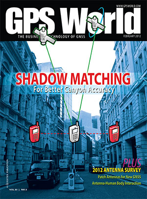
The technological underpinning for stock markets’ techno-darlings doesn’t always work perfectly. That problem produces lost revenue and lost value. So Uber, for one, has done something about it, partly based on research developed by Paul Groves at University College London and featured in the February 2012 cover story of GPS World.
Smartphones finding each other in the urban landscape constitute Uber’s business basis. When driver and rider can’t find each other, because they’re on opposite sides of the street or even opposite sides of the block, a ride can’t happen. In the GPS world, we call this multipath, reflected signals, shadowing or simply urban canyon. In Uber parlance it is “wasted supply.”
To eradicate it, Uber acquired Shadow Maps in 2016 and has integrated the company’s technology into the Uber app. Beta testing now goes on in 15 cities; early results indicate that positioning accuracy has improved twofold.
The Shadow Maps process, derived from Groves’ shadow-matching concept, directs the Uber algorithm to examine a 3D rendering of the cityscape and perform a probabilistic estimate of user location based on — simultaneously — which satellites are in direct line-of-sight and which aren’t, in conjunction with predicted satellite location, or almanac.
The process uses ray tracing, color-coding satellite signals by strength to predict likely locations. Each probability calculation takes 20–100 milliseconds, and can run every four seconds for riders and more frequently for drivers, according to Uber engineers and former Shadow Maps principals Andrew Irish and Danny Iland.
“You just want to have a better, tighter estimate to account for how much faster cars move,” Irish said.
Prior Work. Paul Groves has researched this area for nearly a decade at the Space Geodesy and Navigation Laboratory, University College London, where he is an associate professor. Lei Wang won ION’s Parkinson Award for his Ph.D. thesis on shadow matching and now works at Apple. Marek Ziebart is a professor and vice-dean, research, UCL.
“There are many different approaches to 3D-mapping-aided GNSS and several different research groups around the world working on them,” said Groves. “At UCL, we have been integrating shadow matching with 3D-mapping-aided GNSS ranging algorithms. We now have a real-time demo system running on an Android smartphone, albeit limited to Central London. By making full use of the new Android ‘raw measurements’ capability, we get around a factor of 5 accuracy improvement over conventional single-epoch GNSS in dense urban areas.”
“It’s great to see people actually making use of our research rather than it just languishing in research papers. The more widely that shadow matching and other 3D-mapping-aided GNSS techniques are used, the better.”
In February 2012, Groves and his co-authors presciently wrote:
“A practical shadow-matching algorithm must be implementable in real time on a mobile device. Three models may be considered.
A network-based solution, whereby GNSS measurements are transmitted to a server, which stores the building boundary data, computes a solution and then sends it to the user.
A handset-based solution, where the shadow-matching algorithm is run on the handset, which also stores the building boundary data.
A hybrid model, whereby the shadow-matching algorithm runs on the handset, but the building boundary data is streamed from a server as and when required.
“Using stored or streamed building boundaries, fewer than 50 comparison and addition operations are required to calculate an overall shadow-matching score for one candidate position with two GNSS constellations. Therefore, shadow matching may be performed in real time on a mobile device with several hundred candidate positions, where necessary.”
The magazine article was based on a presentation at the European Navigation Conference 2011 in London. The authors will present their latest research, reflecting significant progress over the last seven years, at ION GNSS+ 2018 in Miami, Sept. 24-28.
Integrations of MEMS sensors with signal conditioning and radio communications form “motes” with extremely low-cost and low-power requirements and miniaturized form factor. Now standard features in modern mobile devices, MEMS accelerometers and gyros can be combined with absolute positioning technologies, such as GNSS or other wireless technologies, for user localization.
Navigation has been revolutionized by micro-electro-mechanical systems (MEMS) sensor development, offering new capabilities for wireless positioning technologies and their integration into modern smartphones.
These new technologies range from simple IrDA using infrared light for short-range, point-to-point communications, to wireless personal area network (WPAN) for short range, point-to multi-point communications, such as Bluetooth and ZigBee, to mid-range, multi-hop wireless local area network (WLAN, also known as wireless fidelity or Wi-Fi), to long-distance cellular phone systems, such as GSM/GPRS and CDMA.
With these technologies, navigation itself has become much broader than just providing a solution to location-based services (LBS) questions, such as “Where am I?” or “How to get from start point to destination?”
It has moved into new areas such as games, geolocation, mobile mapping, virtual reality, tracking, health monitoring and context awareness.
MEMS sensors are now essential components of modern smartphones and tablets. Miniaturized devices and structures produced with micro-fabrication techniques, their physical dimensions range from less than 1 micrometer (μm, a millionth of a meter) to several millimeters (mm).
The types of MEMS devices vary from relatively simple structures having no moving elements to complex electromechanical systems with multiple moving elements under the control of integrated microelectronics.
Apart from size reduction, MEMS technology offers other benefits such as batch production and cost reduction, power (voltage) reduction, ruggedization and design flexibility, within limits.
Wireless sensor technology allows MEMS sensors to be integrated with signal-conditioning and radio units to form “motes” with extremely low cost, small size and low power requirements.
New miniaturized sensors and actuators based on MEMS are available on the market or in the development stage.
Today’s smartphone sensors can include MEMS-based accelerometers, microphones, gyroscopes, temperature and humidity sensors, light sensors, proximity and touch sensors, image sensors, magnetometers, barometric pressure sensors and capacitive fingerprint sensors, all integrated to wireless sensor nodes.
These sensors were not initially intended for navigation. For instance, accelerometers are used primarily for applications such as switching the display from landscape to portrait as well as gaming.
These embedded sensors, however, are natural candidates for sensing user context. Because of their locating capabilities, people are getting used to the location-enabled life.
MEMS accelerometers and gyros, for instance, can be employed for localization in combination with absolute positioning technologies, such as GNSS or other wireless technologies.
WIRELESS OPTIONS IN SMARTPHONES
Various wireless standards have been established. Among them, the standards for Wi-Fi, IEEE 802.11b and wireless PAN, IEEE 802.15.1 (Bluetooth) and IEEE 802.15.4 (ZigBee) are used more widely for measurement and automation applications.
All these standards use the instrumentation, scientific and medical (ISM) radio bands, including the sub-GHz bands of 902–928 MHz (US), 868–870 MHz (Europe), 433.05–434.79 MHz (US and Europe) and 314–316 MHz (Japan) and the GHz bands of 2.4000-2.4835 GHz (worldwide acceptable).
In general, a lower frequency allows a longer transmission range and a stronger capability to penetrate through walls and glass.
However, due to the fact that radio waves with lower frequencies are more easily absorbed by materials, such as water and trees, and that radio waves with higher frequencies are easier to scatter, effective transmission distance for signals carried by a high-frequency radio wave may not necessarily be shorter than that of a lower frequency carrier at the same power rating.
The 2.4-GHz band has a wider bandwidth that allows more channels and frequency hopping and permits compact antennas.
Wireless Fidelity. Wi-Fi (IEEE 802.11) is a flexible data communication protocol implemented to extend or substitute for a wired local area network, such as Ethernet. The bandwidth of 802.11b is 11 Mbits and it operates at 2.4 GHz frequency.
Originally a technology for short-range wireless data communication, it is typically deployed as an ad-hoc network in a hot-spot. Wireless networks are built by attaching an access point (AP) to the edge of a wired network.
Clients communicate with the AP using a wireless network adapter similar to an Ethernet adapter. Beacon frames are transmitted in IEEE 802.11 Wi-Fi for network identification, broadcasting network capabilities, synchronization and other control and management purposes.
Timers of all terminals are synchronized to the AP clock by the timestamp information of the beacon frames. The IEEE 802.11 MAC (Media Access Control) protocol utilizes carrier sensing contention based on energy detection or signal quality.
RSSs and MAC addresses of the APs are location-dependent information that can be adopted for positioning. For localization of a mobile device, either cell-based solutions or (tri)lateration and location fingerprinting are commonly employed.
Bluetooth. A wireless protocol for short-range communication, Bluetooth (IEEE 802.15.1) uses the 2.4-Hz, 915-MHz and 868-MHz ISM radio bands to communicate at 1 Mbit between up to eight devices. It is mainly designed to maximize the ad-hoc networking functionality (Wang et al., 2006).
Compared to Wi-Fi, the gross bit rate is lower (1 Mbps), and the range is shorter (typically around 10 m). On the other hand, Bluetooth is a “lighter” standard, highly ubiquitous (embedded in most phones) and supports several other networking services in addition to IP. For positioning either tags (small size transceivers) or Bluetooth low energy (BLE) iBeacons are common.
Each tag has a unique ID that can be used for localization. iBeacon is a low-energy protocol developed by Apple; compatible hardware transmitters, typically so-called beacons, broadcast their identifier to nearby portable electronic devices.
The technology enables smartphones, tablets and other devices to perform actions when in close proximity to an iBeacon whereby a universally unique identifier picked up by a compatible app or operating system is transmitted.
The identifier and several bytes sent with it can be used to determine the device’s physical location, track customers, or trigger an LBS action on the device such as a check-in on social media or a push notification.
One application is distributing messages at a specific point of interest — for example, a store, a bus stop, a room or a more specific location like a piece of furniture or a vending machine. This is similar to previously used geopush technology based on GNSS, but with a much reduced impact on battery life and much extended precision.
Another application is an indoor positioning system, which helps smartphones determine their approximate location or context. With the help of an iBeacon, a smartphone’s software can approximately find its relative location to an iBeacon.
iBeacon differs from some other LBS technologies as the broadcasting device (beacon) is only a one-way transmitter to the receiving smartphone, and necessitates a specific app installed on the device to interact with the beacons.
This ensures that only the installed app (not the iBeacon transmitter) can track users, potentially against their will, as they passively walk around the transmitters. Localization is based on proximity sensing and cell-based solutions.
ZigBee. ZigBee is an IEEE 802.15.4-based specification for a suite of high-level communication protocols used to create personal area networks with small, low-power digital radios.
ZigBee operates in the ISM radio bands: 2.4 GHz in most jurisdictions worldwide, 784 MHz in China, 868 MHz in Europe and 915 MHz in the U.S. and Australia. Data rates vary from 20 kbit/s (868-MHz band) to 250 kbit/s (2.4-GHz band).
It adds network, security and application software and is intended to be simpler and less expensive than other WPANs such as Bluetooth or Wi-Fi.
Owing to its low power consumption and simple networking configuration, ZigBee is best suited for intermittent data transmissions from a sensor or input device.
Applications include wireless light switches, electrical meters with in-home displays, traffic management systems and other consumer and industrial equipment that requires short-range low-rate wireless data transfer.
Distances are limited to 10–100 m line-of-sight, depending on power output and environmental characteristics. ZigBee localization techniques usually use measurement of signal strength (RSS-based positioning) in conjunction with (tri)lateration and fingerprinting.
COMPARING STANDARDS
Table 1 compares the three wireless standards most suitable for a wireless sensor network. The standards also address the network issues for wireless sensors. Three types of networks (star, hybrid and mesh) have been developed and standardized.
TABLE 1. Comparison of Wi-Fi, Bluetooth and ZigBee.
Bluetooth uses star networks, composed of piconets and scatternets. Each piconet connects one master node with up to seven slave nodes, whereas each scatternet connects multiple piconets, to form an ad-hoc network. ZigBee uses hybrid star networks of multiple master nodes with routing capabilities to connect slave nodes, which have no routing capability.
The most efficient networking technology uses peer-to-peer mesh networks, which allow all the nodes in the network to have routing capability. Mesh networks allow autonomous nodes to self-assemble into the network and allow sensor information to propagate across the network with high reliability and over an extended range.
They also allow time synchronization and low power consumption for the “listeners” in the network, thus extending battery life. When a large number of wireless sensors need to be networked, several levels of networking may be combined.
For example, an IEEE 802.11 (Wi-Fi) mesh network comprised of high-end nodes, such as gateway units, can be overlaid on a ZigBee sensor network to maintain a high level of network performance.
A remote application server (RAS) can also be deployed in the field close to a localized sensor network to manage the network, to collect localized data, to host web-based applications, to remotely access the cellular network via a GSM/GPRS or a CDMA-based modem and, in turn, to access the internet and remote users.
ESTIMATION METHODS
The three most common position estimation methods are cell-based positioning (cell-of-origin, CoO), (tri) lateration and location fingerprinting, regarding achievable positioning accuracies as well as their advantages and disadvantages.
They provide different level of accuracies ranging from dm up to tens of m. Compared to (tri)lateration and fingerprinting, the principle of operation of CoO is the most straightforward and simplest. Disadvantages range from the requirement of a large number of devices or receivers as well as their performance in dynamic environments.
All these techniques provide absolute localization capabilities. Their disadvantage is that position fixes are lost if no coverage or signal availability is available.
Thus, combination with other technologies to bridge loss of lock of wireless signals (for example, no GNSS reception) is required. In smartphones, motion sensors exists that can be employed for inertial navigation (IN). In this article, these sensors are also referred to as inertial sensors.
In the simplest case, a position solution can be obtained from the relative measurements of the inertial sensors via dead reckoning (DR). The accelerometers, for instance, can be used by a pedestrian to count steps while walking and the gyroscope and magnetometer can provide the direction of movement.
These sensors have therefore substantially won on importance for navigation solutions.
MEMS LOCATION SENSORS
For many navigation applications, improved accuracy and performance is not necessarily the most important issue, but meeting performance at reduced cost and size is.
In particular, small navigation sensor size allows the introduction of guidance, navigation and control into applications previously considered out of reach. In this context, the small size, extreme ruggedness and potential for very low-cost and weight means of MEMS gyros and accelerometers have been, and will be, able to utilize inertial guidance systems — a situation that was unthinkable before MEMS.
The reduction in size of the sensing elements, however, creates challenges for attaining good performance. In general, the performance of MEMS inertial measurement units (IMUs) continues to be limited by gyro performance, which is typically around 10 to 30 deg/h, rather than by accelerometer performance, which has demonstrated tens of micro-g or better.
MEMS has struggled to reach high-accuracy tactical-grade quality.
MEMS Accelerometors. MEMS accelerometers are either pendulous/displacement mass type or resonator type. The former use closed-loop capacitive sensing and electrostatic forcing while the latter are based on resonance operation.
Both can detect acceleration in two primary ways: either displacement of a hinged or flexure-supported proof mass under acceleration, producing a change in a capacitive or piezoelectric readout, or frequency change of a vibrating element caused by a change in its tension induced by a change of loading from a seismic-proof mass.
Pendulous types can meet a wide performance range from 1 mg for tactical systems down to 25 μg. Resonant accelerometers or VBAs can reach higher performance down to 1 μg.
MEMS-Based Gyroscopes. For MEMS INS, attaining suitable gyro performance is more difficult to achieve than accelerometer performance. Fundamentally, MEMS gyros fall into four major areas: vibrating beams, vibrating plates, ring resonators and dithered accelerometers.
Gyroscopes are usually built as hybrid solutions, with sensor and electronics as two separate chips. The operational principle for all vibratory gyroscopes is based on the utilization of the Coriolis force.
If a mass is vibrated sinusoidally in a plane, and that plane is rotated at some angular rate Ω, then the Coriolis force causes the mass to vibrate sinusoidally perpendicular to the frame with amplitude proportional to the angular rate Ω.
Measurement of the Coriolis-induced motion provides knowledge of the angular rate Ω. This rate measurement is the underlying principle of all quartz and silicon micro-machined.
These gyroscopes are usually designed as an electronically driven resonator, which are often fabricated out of a single piece of quartz or silicon. The output is demodulated, amplified and digitized. Their extremely small size, combined with the strength of silicon, makes them ideal for very high-acceleration applications.
For purely surface micro-mechanical gyroscopes, given their small sizes and capacitances, monolithic integration is an option to be considered not so much for cost as for performance.
Combined IMUs. Further interest in all-accelerometer systems, which are also referred to as gyro-free, arises because high-performing small gyroscopes are very difficult to produce. Two approaches are typically used. In the first, the Coriolis effect is utilized.
Typically, three opposing pairs of monolithic MEMS accelerometers are dithered on a vibrating structure (or rotated). This approach allows the detection of the angular rate Ω. In the second, the accelerometers are placed in fixed locations and used to measure angular acceleration.
In both approaches, the accelerometers also measure linear acceleration, enabling a full navigation solution. In the direct approach, however, the need to make one more integration step makes it more vulnerable to bias variations and noise, so the output errors grow by an order of magnitude faster over time than when using a conventional IMU.
However, these devices only provide tactical-grade performance, and are most useful in GNSS-aided applications. The concept of a navigation-grade all-accelerometer IMU requires accelerometers with accuracies on the order of nano-g’s or better, and with large separation distances.
Use of all-accelerometer navigation for GNSS-unavailable environments will likely require augmentation with other absolute positioning techniques. Further sensor size reductions are underway through the combination of two in-plane (x- and y-axis) and one out-of- plane (z-axis) sensors on one chip. These multi-axes gyroscopes and accelerometer chips produce IMUs as small as 0.2 cm3.
Barometric Sensors. Barometric pressure sensors embedded in smartphones and other mobile devices demand small size, low cost and high-accuracy performance. The key element of a pressure sensor is a diaphragm containing piezoresistors which can be formed by ion implantation or in-diffusion.
Applied pressure deflects the diaphragm and thereby changes the resistance of the piezoresistors. By arranging the piezoresistors in a Wheatstone bridge, an output signal voltage can be generated. The measurement sensitivity of the pressure sensor is determined by the strain at the bottom plane of the diaphragm, whereby larger strain leads to higher sensitivity.
These altimeters are increasingly used in smartphones and other navigation systems. They can enable altitude determination of the user, for example, to determine the correct floor in a multi-storey building.
Pedestrian Dead Reckoning (PDR). The MEMS accelerometers embedded in the mobile device can be used to estimate the distance traveled from the accelerations made while walking, and magnetometers and gyroscopes to obtain user heading. Starting from a known position, determined by GNSS or other absolute positioning technique, the current position of the user can then be dead-reckoned using observations of the inertial sensors.
DR techniques differ from other localization techniques because the position is always calculated relative to the previously calculated position and no correlation with the real position can be made. PDR can give the best available information on position; however, it is subject to significant cumulative errors, i.e., either compounding, multiplicatively or exponentially, due to many factors as both velocity and direction must be accurately known at all instants for position to be determined accurately.
The accuracy of PDR can be increased significantly by using other, more reliable methods — GNSS or another absolute positioning technique such as Wi-Fi — the combination with inertial sensors produces more reliable and accurate navigation.
Altitude Determination. For navigation, determination of the altitude of the user can be of great importance, for example in determining the correct floor in a multi-storey building. Barometric pressure sensors can provide this data, augmenting the inertial sensors that can usually only provide reliable 2D localization.
Furthermore, if only three GNSS satellites are visible, providing a 2D positioning solution, pressure sensors can aid 3D localization.
Altitude determination with a barometric pressure sensor can be performed relatively from a given start height — for example, obtained from GNSS outside the building or from a known height point in the indoor environment.
As the user walks inside the building and up stairs or elevator to other floors, differences in air pressure can be calculated using a simple relationship between the pressure changes and height differences.
For conversion of the air pressure in a height difference, the mean value of the temperature at both stations is also required; MEMS infrared temperature sensors are increasingly found in smartphones to provide this.
Activity Detection. Low-cost inertial and motion sensors provide a new platform for dynamic activity pattern inference. Human activity recognition aims to recognize the motion of a person from a series of observations of the user’s body and environment.
A single biaxial accelerometer can classify six activities: walking, running, sitting, walking upstairs, walking downstairs and standing.
Until recently, sensors on the body have been used for activity detection, and until recently only a few studies have used a smartphone to collect data for activity recognition.
Smartphone accelerometers recognize acceleration in three axes as shown in Figure 1. Different motion sequences can thereby be ascertained.
Figure 1. Smartphone coordinate frame (left) and global horizontal coordinate system (right).
If a smartphone is held horizontally in the hand during a forward motion, then an acceleration in the y-axis is induced. When working with accelerations, two approaches can be applied to measure the linear displacement: integration of the accelerations or step detection combined with step size estimate.
In the first case, the distance traveled can be theoretically calculated by integrating the accelerations once for velocity, twice for distance.
Due to the double integration, however, any error in the signal will propagate rapidly, so the drift on the received signals from the accelerometer makes it impossible to use integration for walks of more than a few seconds.
The Zero Velocity Update (ZUPT) technique, where the velocity is reset to zero between every consecutive step when the foot is stationary for a small amount of time, can overcome this. Any error produced during one step has no influence on following steps. ZUPT can only be used when the accelerometer is placed on the foot, taking advantage of the stationary period between footsteps.
In the latter case, the distance traveled is obtained from step counts by processing the fluctuating vertical accelerations, which cross zero twice with every step. When the number of steps and the step size are acquired, the distance can be calculated by multiplication.
Figure 2 shows the recorded acceleration of a walking person in the z-axis, with significant maxima and minima that enable step-counting. Correction for the gravity effect on the x-, y- and z-axes of the smartphone’s local coordinate system is key to the correct determination of accelerometer-derived distance traveled. The MEMS-based three-axis accelerometer allows the device to detect the force applied along the three axes in order to accomplish specific functions based on predefined configurations.
Figure 2 . Typical recording of accelerometer sensor data in z-axis of a walking user.
The mobile device can be oriented in such that one of the axes is aligned in the direction of movement or heading (for example, y-axis), the positive x-axis is pointing rightward and the positive z-axis is upward (compare Figure 1). When the y-axis is horizontal, the gravity effect will be fully reflected on the z-axis.
However, a cell phone will most likely be placed by a user into a pocket or bag. Therefore, most existing step detection algorithms cannot be used directly — adjustments have to be made to take into account the orientation of the accelerometers. Because a phone can be placed with any side up or down, the accelerations are observed to determine which axis is the most vertical one.
The accelerations of the axis that is pointing directly to the center of the Earth has a value of 1 g due to gravity. So if the smartphone is lying flat on a table, with the display side up, then the z-axis of the accelerometer would theoretically have a value of 1,000 mg.
If the phone is put crooked (not along one of the axes) in someone’s pocket, the values will be lower than 1,000 mg. So to detect which accelerometer has the most vertical axis, the absolute average of the last 30 samples, or 1.2 seconds, of all three axes of the accelerometers of which the absolute value is closest to 1 g, is the most vertical axis and the accelerometer to use.
SYSTEM COMPARISON
Table 2 compares the most commonly used location sensors and systems in mobile devices classified depending on their positioning capability — absolute or relative — and on their type. A meaningful combination in form of a hybrid solution will produce the best performance for localization of a mobile smartphone user.
TABLE 2. Specifications of the most commonly used location sensors and systems in mobile devices.
Combining MEMS, Wireless. For the majority of indoor navigation systems, the combination of MEMS sensors and wireless options provides the optimal solution. MEMS sensors can provide relative positioning information, with an unbounded accumulation of location errors over time. Wireless systems provide an absolute position in either a local or global coordinate frame, independent of previous estimates without integrating measurements over time. The combination of these two technologies takes advantages of the strengths of both, producing a more robust position solution.
CONCLUSIONS
The increasing ubiquity of location-aware devices has pushed the need for robust GNSS-like positioning capabilities in difficult environments.
No single sensor or technique can meet the positioning requirements for the increasing number of safety- and liability-critical mass-market applications.
Integration is one approach to improving performance level, but a significant step change in high-performance positioning in GNSS-difficult environments, higher performance level are required from MEMS and wireless technologies.
ALLISON KEALY is a professor of geospatial science at Royal Melbourne Institute of Technolgy University, Australia. She holds a Ph.D. in GPS and geodesy from the University of Newcastle upon Tyne, UK. He is co-chair of FIG Working Group 5.5. Ubiquitous Positioning and vice president of the International Association of Geodesy (IAG) Commission 4: Positioning and Applications.
GÜNTHER RETSCHER is associate professor in geodesy and geoinformation at the Vienna University of Technology, with a Ph.D. in applied geodesy. He is co-chair of IAG Sub-Commission 4.1 on Emerging Positioning Technologies and GNSS Augmentation and of the IAG/Fig Working Group on Multi-Sensor Systems.
The Trimble Catalyst software-defined GNSS receiver for Android devices is now available through Trimble’s global distribution network.
Trimble Catalyst DA1 antenna attaches to a smartphone running a Catalyst-enabled app.
Through Catalyst and a special antenna, customers can access positioning-as-a-service to collect geolocation data with Trimble or third-party apps on smartphones, tablets and mobile handhelds.
When combined with a plug-and-play digital antenna and subscription to the Catalyst service, the receiver provides on-demand GNSS positioning capabilities to turn consumer Android devices into centimeter-accurate data-collection systems.
Catalyst requires only a few components:
Any location-enabled mobile app.
A Catalyst subscription, with accuracy options ranging from one meter to centimeter level.
Trimble’s small, lightweight DA1 antenna that plugs directly into Android smartphones and tablets.
“Our goal has always been to extend the accessibility of high-accuracy positioning to a broader base of geospatial and non-geospatial professionals,” said Ron Bisio, vice president of Trimble Geospatial. “Trimble Catalyst represents a new era of GNSS technology by making high-precision positioning a reality for new user segments around the world. With economical on-demand service, it puts high-accuracy in the palm of anyone’s hand — it’s revolutionary.”
Both Trimble and third-party development teams have produced a range of Catalyst-enabled applications for geographic information system (GIS) data acquisition, cadastral land management, topographic mapping and ground control for unmanned aircraft systems (UAVs).
Also, the Trimble Catalyst solution includes a software development kit (SDK) for building mobile applications with integrated professional workflows.
“Trimble is enabling us to deliver better solutions for our customers thanks to the level of integration that the SDK provides,” said Paul Brodin of Korec Group. “It allows us to provide sophisticated solutions that are innovative, easy to use and remove the technical complexity associated with high-accuracy workflows.”
Trimble Catalyst service subscriptions and the Catalyst DA1 antenna are now available through Trimble’s Authorized GIS Distribution Network. Catalyst availability, pricing, subscription and accuracy may vary by region. Catalyst-enabled apps for Android can be found in the Google Play Store.
Esri is partnering with GISinc to analyze customer behavior to help retailers increase sales.
Esri will integrate itsspatial analytics platform with GISinc’s indoor mapping capabilities to analyze data collected by sensor-enabled overhead smart lighting systems and from opt-in mobile data from customer phones. The solution will enable retailers to track behaviors, using information including customer locations inside the store and items selected for purchase. The store can then tap into such data to improve customer assistance and position merchandise in the places most likely to attract purchases.
“Analyzing customer choices and mapping go hand in hand,” said Sonny Beech, Internet of Things (IoT) business development manager at GISinc. “Why a person bought something where they did is an example of spatial data. Using ArcGIS analytics, we can enable retailers to make more strategic decisions about where to place merchandise and in-store marketing materials.”
With more than two-thirds of consumers using smartphones while shopping in brick-and-mortar stores, retailers have to deliver more relevant experiences by becoming more precise in how they interact with shoppers. In-store location technologies provide opportunities for retailers to increase touch points in the aisle and on the shelf by delivering messaging and services in real time based on a customer’s location in the store.
Studies show that the spatial customer behavior analysis Esri provides can boost the probability of purchase by up to 70 percent and increase basket size by up to 60 percent for smartphone-enabled shoppers, Esri said.
“Esri enables retailers to access vast amounts of customer information while allowing the customers themselves to take advantage of advanced analytics,” said Gary Sankary, retail industry manager at Esri. “With the widespread use of smartphones during in-store shopping, indoor mapping provides businesses with a tool to understand shopper behavior and improve sales accordingly.”
Indoor-mapping initiatives and smart lighting systems, like other IoT implementations, have become more affordable and accessible — in fact, much of the technology can be integrated directly into the infrastructure of a brick-and-mortar store. Customers benefit by downloading mobile apps and opting in to shared-data environments that make the shopping experience more efficient and enjoyable.
 On Aug. 19, the U.S. Federal Communications Commission (FCC) granted a request for authorization from AT&T Services to use Galileo for emergency location purposes.