Tag: Spirent

  • Recording and Replay for Multiple Constellations and Frequency Bands

    Recording and Replay for Multiple Constellations and Frequency Bands

    The design and verification of a new class of portable wideband record-and-playback system considers the relative merits and limitations of both simulator and record/replay approaches. The authors also discuss the benefits of the different test approaches to the development and characterization of various GNSS receiver types.

    By Steve Hickling and Tony Haddrell

    As new GNSS systems become available, and users take receivers to ever more challenging environments, the need for repetitive and repeatable testing during development grows ever stronger. Simulators have traditionally demonstrated performance and repeatability in the laboratory environment, and this approach remains the only option for planned signals not yet broadcast from space. However, this approach is becoming more complex as the number of GNSS signals and their reception environments increase.

    Another way of testing receivers is through field trials. This allows investigation of conditions difficult to simulate, such as multiple reflections and interferers. These environments, however, are time-varying, and thus not repeatable in the true sense. Therefore, proper comparisons can only be made by assessing all competing receivers in the same trial, and any performance anomalies seen cannot necessarily be tracked down by returning to the same location at some point in the future. Furthermore, developers would like to see for themselves any such anomalies and try to understand and correct them, but it is not always desirable or practical (and certainly not economical) to put development engineers in locations scattered all over the globe.

    To tackle this problem, GNSS signal record-and-replay capability is gaining acceptance as a practical tool for recording a signal environment at a single point in time and replaying at will. In real terms this means a device must receive the radio signals from the GNSS satellites, reduce them to a form suitable for storage, and then recreate signals from the stored data in a manner that makes them look completely real to any receiver under test or development.

    Some receiver manufacturers developed their own capability to do this. Early devices were of necessity restricted in the signals they could handle and store, limited both by budget and available technologies. The basic problems are the amount of data to be stored in real time and the ability to recover it in real time. Even the GPS L1-only low bandwidth C/A code requires at least 2 Mbytes per single second of recording, or more than 100 Mbytes per minute.

    Fortunately, with digital storage technology advances, we can now make use of higher storage capacities (1 TByte of storage is readily available at reasonable cost) and also higher write/read bandwidths (100 MBytes per second is realistic). All we need is some hardware and a processor that can handle the data rates.

    Once we have our wanted signals reduced to some form of digital representation, we can simply store and retrieve them at will, handling the recordings as simple, if somewhat large, data files. This allows file distribution between equipments, and a split between making the recording in the field and replaying it in the laboratory. In fact, many manufacturers have dedicated field recording teams who send the files back to the engineers interested in the signal environments.

    Replaying the signals is in some ways similar to generating simulated signals. In both cases, the starting point is digital data, on the one hand recorded in the field, on the other hand calculated by mathematical algorithms using the scenario specified in the simulator. In both cases the signal is created by generating radio frequency (RF) carriers and modulating them according to the GNSS signal formats.

    Contrast of Two Approaches. None of the characteristics of the record/replay device replace the functionality of the simulator; in fact, both are valid tools for development and testing. For instance, it is not possible with a record/replay device to manipulate individual satellite signals, nor to introduce specific errors in the radio signals. Equally, it is not really possible with a simulator to recreate a particular physical environment made up of many reflected signals, jammers, manmade noise, and moving scenery. With a simulator, the user has control over the power of the received satellite signal, whereas in the recorder the entire signal-to-noise ratio observed at the point of reception has been recorded, and the user can only control the amplitude of the entire noise plus signal.

    Permanent Signal Monitoring

    One other aspect of raw signal recording lies outside the receiver testing topic, but is of interest for GNSS signal monitoring. It uses the ability to record GNSS signals all of the time, in this case from a good signal environment, and then to retain any time spans where an anomaly in the signals has been detected by a monitor receiver. This is comparable to recording security CCTV pictures, where we expect nearly all of the resulting files to be redundant, but can retain the interesting bits to replay over and over for further analysis. For example, if it is known that a given timing receiver installation suffers periodic loss of lock, it is possible to make a recording using the loss of lock to signpost the interesting region in much the same way as a reverse trigger on an oscilloscope.

    Limitations and Compromises

    The sheer function of recording GNSS signals off-air has some built-in limitations. First, the signal recorded represents only a snapshot of the environment, although numerous recordings can be made at, say, busy and quiet times, day and night, etc. This is really a reversal of the “non repeatability” aspect of measuring performance in a particular location. In the recording sense, we only get repeatability, with no guarantee that the scenario captured represents worst case conditions. Thus, going back to the location in the future may or may not provide similar results.

    In addition to this, there are some signal processing aspects that limit the fidelity of the replayed signals. The first is that any recorder must have an external GNSS antenna and a GNSS receiver front-end built in, and this combination will receive both the satellite signals and thermal noise. The level of the noise is much higher than that of the signals if we don’t do any correlation related processing, and the receiver will contribute some more noise of its own (the noise figure of the system). The second aspect is that in downconverting the radio signals to a usable frequency for sampling and storage, the recorder must use some frequency reference of its own, which will contribute some frequency uncertainty and some phase noise (or jitter on the frequency). The final aspect is the digitization of the downconverted signal to get it into a suitable form for manipulation and storage. Since we are essentially sampling noise here (with the GNSS signal buried in it) we need to look at fidelity in reproduction of the noise during playback, and the effect of any signal (a jammer or interferer) that is above the amplitude of the noise. In analyzing this last aspect, we may include the effect of any automatic gain control (AGC) used to present the correct amplitude signal to the analog to digital (A2D) converter.

    A New Simulation Requirement

    We wanted to create a much more comprehensive and flexible device than hitherto available, going part way towards the much more general (and expensive) instrumentation recorders that are currently the only alternative.

    The requirement is for a flexible, self-contained device that can be easily carried or transported for recording purposes, so having an internal battery and built-in control functionality, and simultaneously a device that fits neatly into a networked and externally controlled laboratory environment.

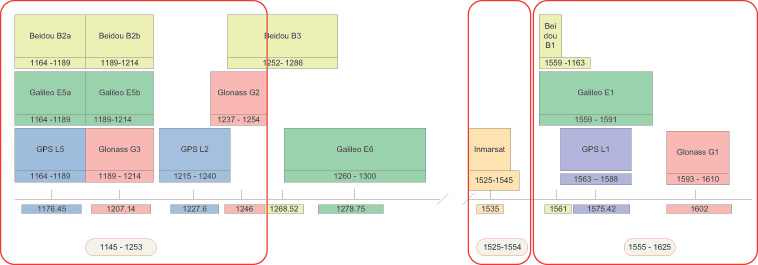
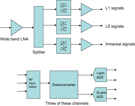
    The first approach was to cover all of the possible GNSS frequency bands, although as more are added with time, we realized that this needed to be moderated somewhat. So the product covers L1, L2, L5 and their derivatives for the differing GNSS systems GPS, GLONASS, Galileo, and BeiDou, and also the Inmarsat commercial band to cover the proprietary augmentation signals used by many high-accuracy receivers (see Figure 1, red outlines).

    FIGURE 1. Frequency bands, outlined in red, supported by the new record-and-replay device.
    FIGURE 1. Frequency bands, outlined in red, supported by the new record-and-replay device.

    The next decision was what bandwidths to allow at each frequency, and how much of this bandwidth could be covered at once. The limitations here are driven by the data storage requirements of the signals being recorded, and the speed that they can be written to disk. The resulting solution allows bandwidths (BW) of up to 30 MHz at each frequency, and any three such bandwidths to be recorded at once. Physically, this is implemented with three channels with the ability to record any of the available frequencies or bandwidths. The user has, therefore, flexibility to set up recording for his particular needs, which may be just L1 covering BeiDou, GPS, Galileo, and GLONASS, or an L1,L2,L5, combination for a survey type application.

    Of course, there are always requests for more capability, and we envisaged early on the ability to stack two devices to give six channels of 30-MHz BW for recording, say, GPS/Galileo and GLONASS at L1, GPS and GLONASS at L2, Galileo/GPS at L5, and an Inmarsat data carrier. See later for how this is achieved.

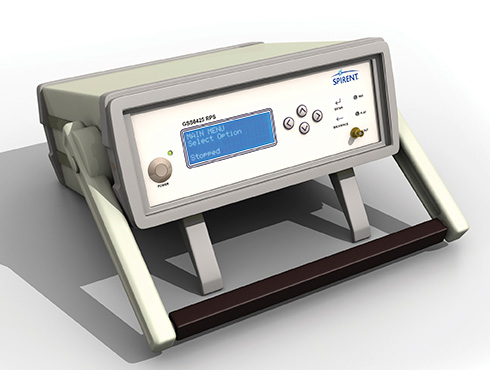
    The whole product has to fit in a portable box with enough battery power for more than one-hour field campaigns, and also be capable of running from mains or vehicle power. The associated antenna needs to cover all of the frequency bands. Figure 2 shows the end result in its standalone configuration.

    Figure 2. Portable solution for recording.
    Figure 2. Portable solution for recording.

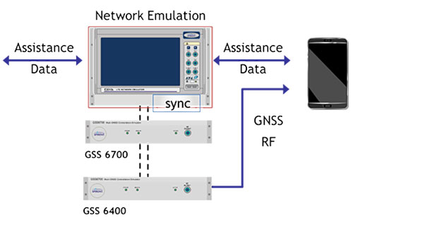
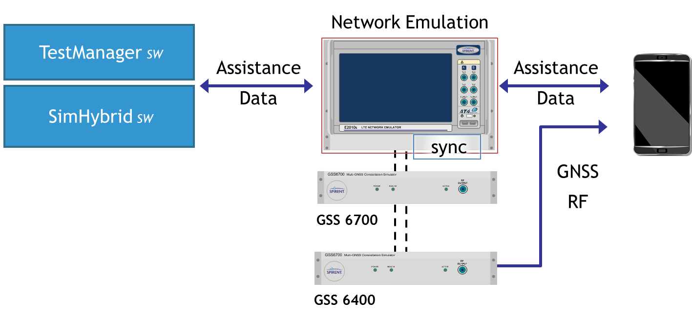
    One additional requirement was placed upon the design, and that is the ability to record and replay non-GNSS data simultaneously with the GNSS signals, and reproduce them, if desired, in synchronism with the replayed signals. This allows time ticks, events, assistance data, sensor data, or even video to be stored and replayed along with the raw signals.

    Architecture and Implementation

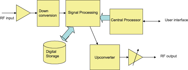
    The new record-and-replay device uses a fast computer running the Linux operating system as its control center and storage/retrieval engine. Dedicated hardware is used to format or recover the raw data, and this has access directly to the computer bus to minimize the delays in writing or reading the mass storage, which in this case is a solid state hard drive (SSD). The overall architecture is shown in Figure 3.

    Figure 3. Concept-level architecture.
    Figure 3. Concept-level architecture.

    The signal recording capability hinges around the RF planning, which has the task of supplying the necessary flexibility without adding more than minimal signal degradation.

    For the RF functionality, the device contains a broadband front end and a three-channel RF amplifier (L1, Imarsat, and L2/L5), filtering the signal down to reasonable bandwidths for later downconversion. Three independent channels of downconversion to baseband I and Q analog signals have access to any of the RF channels and are based upon satellite TV technology architectures. The downconverters have baseband filters that can be commanded to a desired bandwidth by the control processor. This allows the use of narrower bandwidths where possible, allowing more recording time for a lower sampling rate. The baseband signals are sampled at 10 MHz or 30 MHz, paying attention to the Nyquist requirements for pre-digitisation filtering. Two bits for each of the I and Q signals are utilized for packing into the recorded file format. Figure 4 shows the arrangement.

    Figure 4 . The RF architecture.
    Figure 4 . The RF architecture.

    At this stage any additional synchronous data to be recorded, such as truth or assitance data, is inserted into the bit stream, and the data from all the channels in use is combined in a pre-determined format. Dedicated hardware is used for this, and large data buffers are provided to alleviate bottlenecks in sending data to the disks. Each file has an associated definition in a header, and contains synchronization data to allow the device to set up the replay path and recover the data bits in order to reproduce whatever combination was recorded. Note that resulting data files are given the same extension, regardless of content. Data files can be very big (at maximum bandwidth we record about 2.7 Gbytes per minute) and may be difficult to handle once recorded. To assist with this, the device has a second, removable SSD on board, allowing recorded files to be simply popped out of the caddy and shared with another device, or even mailed or couriered. The RF path for the replay consists again of three independent channels, able to generate any of the supported frequencies and modulate upon them the original signals recovered from the stored file. Once again, dedicated hardware and large buffers are needed to unpack the files and send the RF data to the correct channels or to the synchronous data outputs in the case of recorded digital data, as determined by the file header.

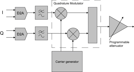
    The data representing the recorded RF is converted back to analog form and filtered before being applied to modulators which regenerate the original channelized signals. Each channel has a programmable attenuator to “level” the amplitude, and the three channels are then combined together before passing through a common attenuator to provide user control over the replayed carrier to noise ratio (C/N0). Figure 5 shows the upconverter arrangement.

    Figure 5. An upconverter channel.
    Figure 5. An upconverter channel.

    All frequencies created within the device need to be traceable to a common reference. In addition, this reference needs to be at least as good as the reference in any receiver to be tested, since both its offset from true frequency and its rates of change will be superimposed on the replayed data. Many commercial-grade GNSS receivers (such as those used in mobile phone) are specifically designed to cope with poor oscillators, for instance a low-grade temperature controlled crystal oscillator (TCXO), whereas more professional receivers may expect a couple of orders of magnitude better performance. We decided, therefore, to include an ovenized oscillator (OCXO) for use both in record and playback modes. One challenge presented by this decision is that the oven is necessarily thirsty for power, and therefore a bigger battery is needed than would otherwise be the case.

    The OCXO used is a 10.23-MHz component, thus allowing direct generation of the wanted GNSS frequencies using integer ratios and avoiding as much phase noise as possible in the various RF channels. A dedicated phase locked loop (PLL) generates a reference for output to other devices, and a 10-MHz input connector is provided to lock the OCXO to an external reference. These capabilities are utilized when combining two such devices, since we must have the same frequency reference in each. Apart from locking the two oscillators together, this configuration also needs time synchronization between the sampling in both devices, and this is achieved via an additional cable connected between the accessory connectors. Once time and frequency synchronized, the devices behave as a single six-channel unit, using external RF splitter/combiners for the RF connections.

    Design Challenges

    RF Total Bandwidth. The GNSS bands covered by the device range from the L5 band to the GLONASS L1 band, a total range of 480 MHz allowing for signal bandwidths. Table 1 shows the relevant bands.

    Whilst the RF front end must be wide open to this range, assuming the use of a single RF input port, it is obviously necessary to provide bandwidth narrowing by filtering as soon as possible, to exclude jammers or carriers using the space between the GNSS bands, and to avoid the sheer noise power overwhelming the RF circuits. Examination of the supported GNSS services shows them essentially packed into two clusters of frequencies, which provide a convenient way of filtering down the RF input into two RF “channels.” This gets the total bandwidth down to about 180 MHz. Figure 1, the opening graphic for this article, shows the groupings. Beidou B3 and Galileo E6 are currently out of scope for this product, but will be supported in a later version.

    The Inmarsat-supported signals are assigned their own RF path, since their structure is data modulated carriers, usually with low SNR. Elsewhere in the Inmarsat band there are more powerful carriers supporting comms traffic, which can “grab” the AGC and therefore cause loss of SNR during the digitization process. Hence this band is processed though its own RF path, maintaining as low a bandwidth as possible consistent with the frequency allocations of the various (proprietary) GNSS augmentation data carriers.

    Tradeoffs. Throughput of the recording or replay paths is the performance limitation of the current architecture. Thus a lot of discussions and simulations concerning possible bandwidth, sampling rates, and bit depth tradeoffs was undertaken at the outset of the design. In addition, we needed to decide whether to sample signals at an IF frequency or at baseband. Trials were conducted to determine the real rates of disk access, which are different to the often quoted write and read speeds of computer interfaces.

    The results of the trials and simulation led us to adopt a maximum average data rate to/from the storage system of 50 Mbytes/second, this being shown to be available over a period of many hours. Actually, at this rate we fill up a 1-Tbyte disk in about five hours.

    To service the GNSS signal bandwidths of interest, again there are two groups of signals. This time we are looking at either the commercial signals (“open service signals” in some systems’ parlance) used by consumer-type receivers, which are relatively narrow band, and the military, high-accuracy, or resilient signals of interest to surveying and precision applications. Therefore, we offer two sampling rates, approximately 10 and 30 MHz, to avoid building large files where more than half of the bandwidth was of no interest to the user.

    Next, we have to look at bit resolution. Given that we have generally a noise-like signal with Gaussian characteristics, if we were looking at digitizing at an intermediate frequency (IF), it can be shown that a 2-bit analog-to-digital converter (A2D) would be sufficient to keep the digitization losses to less than 1dB. Obviously, the fewer number of bits we need to store the better, commensurate with achieving the performance targets.

    Frequency planning for all of the possible frequencies and bandwidths of interest is a complex task. The requirement here was to downconvert each signal of interest to a low IF suitable for digitizing, whilst having control of the bandwidth to eliminate unwanted signals and fulfill the Nyquist criterion. In addition, we wanted each channel to be isolated from the others even when the replay path involving the generation of the IF carriers was considered.

    We therefore decided to downconvert to baseband for each channel, to avoid cross-contamination via the various IFs that would have to be generated for replay. In other words, we adopted an IF of zero Hz. This in turn means that the final bandwidth-determining filters are at baseband, and can readily be controlled by software means rather than having to switch RF paths. By downconverting into quadrature baseband channels, all stored signals are at the same (zero) IF, and crosstalk and imaging during upconversion is avoided.

    Thus the A2D architecture of 2 bits in the inphase (I) and 2 bits in the quadrature (Q) arms of the downconverted signal was adopted. Doing the calculation in terms of stored data, we see that we can operate three channels inside our target storage bandwidth, with a margin left for other features such as storing video at the same time.

    • For 30M samples per second (SPS), each channel has 4 bits or 0.5 bytes
    • Therefore, for three channels the storage bandwidth is 0.5 * 3 * 30 MSPS, or 45 Mbytes/s

    To keep the optimum A2D characteristics, the AGC is designed to adjust the signal amplitude at the converter to give a Gaussian response to the four states determined by the two bits in each arm. The AGC operates independently in each channel. Figure 6 shows the final architecture for the device in block diagram form.

    Figure 6. Final architecture.
    Figure 6. Final architecture.

    Real-Time Data Handling. Storage and retrieval of the digitized signals is carried out by dedicated hardware connected to the RF downconverter, the playback upconverter, and the main computer that “owns” the storage media. Large buffers allow the storage media to lag (record) and lead (playback) the real-time signals in time, and to take short breaks for housekeeping functions. Data is packed into a binary file according to a pre-determined sequence, which in turn is set by the number of channels and bandwidths in use. A file header is generated which contains all of the information necessary for reconstructing the data streams for replay. A synchronization sequence is added at the start of the file to allow recovery of the correct bits for each channel and each baseband quadrature arm, and to the correct timeslots for each component. Destroying the correct time reproduction is the most likely issue to cause faulty replay in any record/replay device. GNSS receivers don’t like discontinuous or slewing time!

    This approach also allows the insertion of external digital data into the file. Providing the data processing hardware is aware of the individual bits into which this data is placed, digital data recorded at the same time as the raw signals may be regenerated synchronously during replay. Thus any data that is applied to a receiver in a real time trial can be available for the same trial any time after the event. Two streams of synchronous data can be recorded per channel potentially making six serial data streams per chassis available.

    User Interfaces

    A final challenge presents itself in the case of user interfaces. Although the operational options of the device are quite complex, there is a requirement to be able to capture field data with just the equipment itself and any necessary antenna setup. Consequently, the product has a display and control keys implemented on the front panel, allowing the user comprehensive access to the internal functions using a menu system and scrolling displays. Alternatively, for operation in a lab environment, a network connected user interface is specified, and this requirement is supported by a webserver running on the main processor in the device. Thus, simply opening a web browser and connecting to the device’s IP address allows full functional control.

    In addition, connecting a mouse, keyboard, and monitor to the device allows access to the main processor, allowing the running of scripts thus providing full control of replays and receiver functions for running continuous tests in an automated laboratory environment. Using this approach, receiver modifications can be tested over many scenarios and locations many times each, to provide statistically relevant results, without taking up operator time. Remote monitoring is possible using the webserver.

    Performance Testing

    A range of tests and trials have been carried out to verify that the product meets its specifications, and to measure the performance in a number of real life scenarios.

    Repeatability, Degradation, Attenuation. The first and most obvious thing to explore is the effect of the record and playback on signal-to-noise ratio. Since the RF circuits add some noise to the signal recorded, we would expect some degradation to take place here. Also, during replay, the receiver under test adds more noise, depending on its noise figure, although this should be the same as would be added when using “live” signals. Many receivers adjust for their noise figure when reporting C/N0 numbers (C/N0 is a signal to noise measurement normalized to a 1-Hz bandwidth and is the standard reported measurement for most GNSS receivers). However, by replaying back the recorded signal and noise at a higher level than would have been received in “live” conditions, we can eliminate almost all of the degradation. In live versus replayed tests for individual satellites using a JAVAD receiver, which allows us to test all of the supported bands and constellations, we found that replay is possible within ±1 dB of the original live signals. Replayed signals were about 10 dB above the original recorded level to achieve this, effectively swamping the receiver’s noise contribution.

    An interesting aspect of controlling the C/N0 this way is the ability to attenuate the replayed signal and, therefore, increase the contribution of the test receiver’s noise figure. Thus, although the recorded C/N0 hasn’t changed, we can attenuate the replay level and use the receiver to add noise.

    This process is not linear, and we obviously have to remove nearly all of the 10-dB excess to get started. The device keeps a table of attenuation vs C/N0 reduction, allowing the user to simply dial up the required C/N0 loss. Since this depends on the receiver noise figure, effects may differ slightly from receiver to receiver. Usefully the table is user definable allowing tailoring to a specific receiver.

    Losses from Phase Noise, Other Factors. This category of degradation is more difficult to quantify, since the effects are on tracking and therefore range and phase measurement rather than signal to noise ratio. One way of looking at this is, therefore, to establish the positioning performance during live and replayed sessions, and measure the differences. This has some complexity, though, since putting the same signals into a receiver multiple times yields differing performance each time, meaning that we have to use some statistical analysis. Of course this isn’t possible on live signals, and is one reason why repeatable replayed signals are so important in developing GNSS receivers. Another aspect is the fact that some of the effects are differential among frequency bands (filter delays, for instance) and across bands as well (group delay) and also occur in the receiver under test, which will have been calibrated to mitigate its own contribution.

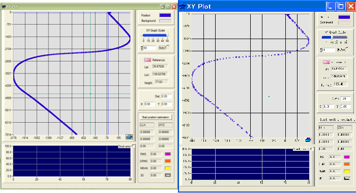
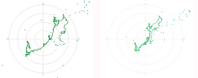
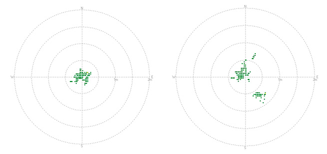
    Figure 7 shows a comparison of static positioning for live and replayed signals using only GPS L1 and a 10-MHz sampling rate with an ST-Ericsson receiver, whilst Figure 8 is from a JAVAD receiver using all possible signals in live mode and GPS L1/L2 and GLONASS L1 in replay. In both cases the degradation is within 1 meter always, and much less than this when statistically analyzed.

    Figure 7. Static position GPS L1 comparison: live left, replayed right.
    Figure 7. Static position GPS L1 comparison: live left, replayed right.
    Figure 9. GPS L1/ L2 with GLONASS L1 comparison.
    Figure 8. GPS L1/ L2 with GLONASS L1 comparison.

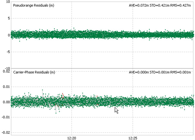
    Another opportunity to measure the effects is to run a zero baseline phase solution, whereby the receiver is used as the “base station” when receiving live signals which are simultaneously recorded. During replay, the same receiver is used as the “rover” with RTK corrections coming from the previously captured live session. In this setup, therefore, we are really only measuring differences in the replayed and live signals, and the usual measurement limitations of the receiver.

    Figure 9 shows the results of one such test, with the pseudorange and carrier phase residuals plotted. This was carried out using two devices in master/slave mode recording GPS L1, L2, L5, and GLONASS L1, L2. As can be seen, the residuals are within “normal” expectations and are measured as 0.42 m RMS for the pseudorange and 1mm RMS for the carrier phase.

    Figure 9.  Residuals from zero baseline replay.
    Figure 9. Residuals from zero baseline replay.

    Drive Test

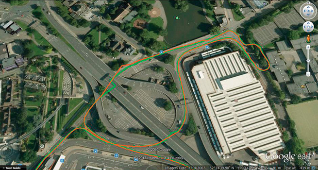
    One of the most common uses for the recorder is to capture the signals at a particular time in a chosen “difficult” environment, A number of representative trials were carried out and we were able to demonstrate consistent results and repeatability. In some cases, the replayed signals yield better performance than live ones, which of course is possible given the differing receiver responses per signal run.

    Also, the more times a receivers sees the same time span, the more ephemeris and iono data it can build up, especially true of built up areas where data acquisition is difficult. Figure 10 shows a small section of the City of Coventry in the UK, where the green trace is the “live” plot and the replayed one is in orange. Much of this route is under roads or buildings.

    Figure 10. Live and replayed drive around in Coventry.
    Figure 10. Live and replayed drive around in Coventry.

    Dynamic Range and Fidelity

    When jamming signals are introduced, the dynamic range comes into play. The earlier discussion of the 2-bit I and 2-bit Q architecture is tested here as the performance of the AGC and A2D is critical in maintaining the fidelity of the GNSS signals in a jamming environment. Note that we are not addressing deliberate jamming here, any “controlled” jammers can be added with an RF mixer at replay. Instead, we are concerned with the everyday jamming environment encountered just about everywhere electronic equipment is deployed.

    A test was carried out to determine the dynamic range of record/playback paths. A simulator was used as a GPS L1 signals source, and progressively larger jamming signal added via an RF power combiner. The resultant C/N0 in a test receiver was plotted using the live signals which were recorded at the same time. A subsequent replay of those signals was then plotted on top of the original C/N0s. The result is in Figure 11.

    Figure 11. Results of the increasing jammer test.
    Figure 11. Results of the increasing jammer test.

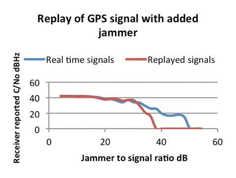
    As can be seen, with low jammer powers the real-time and replayed C/N0s track very closely. The ST-Ericsson receiver we used has some signal processing mitigation built in, and so only shows slow degradation as the jammer power is increased. In the real-time run, it was able to track satellites with the J/S ratio greater than 44 dB (and therefore >25 dB above the noise)

    On the replayed line, we see the dynamic range limitations start to dominate the replayed signal when the J/S reaches about 30 dB, or 11 dB above the noise, which aligns well with the theoretical analysis of the digitization strategy. This range is sufficient for most environments encountered in real tests.

    In Use and Additional Capabilities

    With so much flexibility we find that users have a diverse range of applications for the device. These range from multi-constellation usage at L1 only, allowing BeiDou, Galileo, GLONASS, and GPS to be captured, to full six-channel recordings using GPS, GLONASS, and Galileo at L1, L2, and L5 along with an Inmarsat-based assistance channel. For the first time in this class of device, recording of the “military” bandwidth signals is possible. User feedback has been favorable, especially since the unit opens up new capabilities for receiver development and testing.

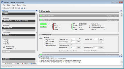
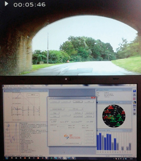
    A small margin of recording bandwidth has been put to use with the ability to record video alongside the raw GNSS signals, and to replay it simultaneously. This allows developers not only to see the performance of their receiver in difficult signal environments, but also to gain a visual idea of the physical environment. Figure 12 shows a receiver  control panel along with video pictures of the recorded environment.

    Figure 12. GPS L1 and video synchronized replay
    Figure 12. GPS L1 and video synchronized replay

    Conclusion

    Early user feedback has validated  the concept behind the device. Although the device will cover additional GNSS constellations and bands as they become operational, for the present the technology is stretched about as far as it can be consistent with the development of a timely and cost effective device. We will continue to address the compromises in the search for more performance, no doubt pushed by user demands.

    Acknowledgment

    The authors thank their colleagues at Integrated Navigation Systems and Spirent UK for support and access to design and user information.

    Manufacturer

    This article describes the GSS6425 from Spirent Communication.


    Steve Hickling obtained his joint physics and electronics degree from the University of Birmingham. He is responsible for Spirent’s GNSS test solutions as lead product manager in the positioning business.

    Tony Haddrell obtained his degree in physics at Imperial College, London, and is technical director at integrated Navigation Systems. He is a consultant to GNSS companies and a visiting lecturer at Nottingham University.

  • Spirent Launches SimSAFE to Address GNSS Signal Vulnerability

    Spirent Launches SimSAFE to Address GNSS Signal Vulnerability

    Spirent Communications, a testing navigation and positioning systems company, today announced the introduction of Spirent SimSAFE, a software solution that concurrently simulates legitimate Global Navigation Satellite System (GNSS) constellations and spoofed or hoax signals to evaluate receiver resilience and help develop counter measures. SimSAFE was developed in conjunction with Qascom, GNSS signal security and authentication experts.

    As GNSS become increasingly embedded in modern infrastructure for application timing and device positioning, the opportunities for interference and spoofing attacks become greater, Spirent said. Hoax or spoofing attacks work by mimicking genuine GNSS signals, which mislead GNSS receivers. From mobile telephony to Internet banking, GNSS timing signals are used in many key systems, and yet there is no requirement on GNSS equipment to demonstrate any degree of robustness to block or even detect malicious attacks that disrupt performance. Often, affected receivers do not recognize when they are receiving fake signals and continue to operate normally, but provide false time or position information.

    “GNSS signal vulnerability is becoming a significant issue,” said John Pottle, marketing director of Spirent’s Positioning Division. “SimSAFE is the first tool to help develop systems that will detect and counter spoofing attacks. This solution is unique in being able to provide a means of both emulating a spoof attack and monitoring a receiver under attack to evaluate mitigation strategies and countermeasures.”

    SimSAFE is a fully controllable laboratory-based, non-radiated test solution to evaluate a receiver’s response to a wide range of spoofing attacks. The test tool generates simulated spoofing attacks that can be aligned with genuine signals from an antenna or locally generated “genuine” signals using a Spirent GNSS simulator. This allows users to simulate a wide range of sophisticated attacks, monitor the response of the receiver under attack and evaluate the effectiveness of proposed countermeasures to then improve resilience against such attacks.

    simSafe_Spirent
    screenshot: Spirent’s SimSAFE

    In essence Spirent’s SimSAFE spoofing test bed does two things:

    1. Generates simulated spoofing attacks where a Spirent RFCS is controlled to represent a hoax signal synchronized with a “genuine” signal which can be ambient GNSS or itself generated by simulation.
    2. Monitors a GNSS receiver subject to simulated spoofing attack in order to evaluate and refine mitigation strategies or countermeasures.

    The two principal applications of SimSAFE are:

    1. The evaluation of the vulnerability of a user’s receiver when exposed to a wide range of simulated spoofing attacks.
    2. The evaluation and refinement of spoofing mitigation techniques, signal authentication strategies or countermeasures. This work can be conducted using any receiver of the user’s choice; however, a range of receiver monitoring tools supplied with SimSAFE are enabled if the receiver supports Septentrio Binary File (SBF). A suitable Septentrio receiver is supplied in the standard configurations for this purpose.
  • Spirent Announces Carrier-Approved A-GNSS Record and Playback Solution for Mobile Device Testing

    Spirent Announces Carrier-Approved A-GNSS Record and Playback Solution for Mobile Device Testing

    Spirent now offers A-GNSS record and playback capabilities for mobile device testing.
    Spirent now offers A-GNSS record and playback capabilities for mobile device testing.

    Spirent Communications today announced the availability of carrier-approved Assisted GNSS Record and Playback capabilities on its Hybrid Location Technology Solution (HLTS).  This new A-GNSS Record and Playback capability provides unprecedented realism and repeatability by recording GNSS signals in the field and delivering synchronized assistance data over a radio access interface to test the A-GNSS positioning performance of mobile devices in the lab.

    “With user location playing a key role in most smartphone services and applications, A-GNSS positioning performance greatly influences the end-user experience,” said Nigel Wright, vice president of wireless, Spirent Communications.  “This new A-GNSS Record and Playback solution enables device manufacturers and network operators, as well as chipset and technology vendors, to accurately test this essential technology using real-world field conditions.  This helps ensure high quality LBS and emergency service performance for every mobile subscriber.”

    Combining GNSS signals from multiple satellite positioning systems (such as GPS and GLONASS) with assistance data delivered by the network to the device, A-GNSS is regarded as the most universal and precise positioning technology. As such, it is used in mobile devices to support the location information required by commercial services, social media and emergency services such as E911.

    Although established A-GNSS simulation tools play an important role in generating repeatable and reliable controlled environments in the lab, they can have limitations when it comes to representing the full range of challenging conditions experienced by mobile users on live networks. Spirent’s A-GNSS Record and Playback addresses these limitations by capturing conditions in the field and playing them back in a reliable and repeatable lab environment. This helps to reduce device time to market and control testing cost by reducing the need for extensive field testing.

    Spirent HLTS is recognized by the industry for its unique capabilities that span a wide range of test requirements from early R&D phases to mobile device acceptance. The HLTS now incorporates Spirent’s GSS6400 GNSS Record and Playback System (RPS), together with patent-pending SimHybrid software that generates and delivers the correct assistance data, synchronized with the recorded GNSS signals.

    For more information on Spirent HLTS and A-GNSS Record and Playback, visit the Spirent website.

  • Spirent Demonstrates Solution That Helps Reduce GNSS Vulnerability

    Spirent Demonstrates Solution That Helps Reduce GNSS Vulnerability

    Spirent-Qascom

    Spirent Communications, a navigation and positioning systems testing company, has teamed up with Qascom, an expert in GNSS signal security and authentication, to develop a test tool that reproduces spoofing attacks in a controlled laboratory environment.

    The collaborative solution will be launched commercially later in 2013, and was previewed at ION GNSS+ in September in Nashville, Tennessee.

    The test bed will concurrently simulate legitimate GNSS constellations and spoofed or hoax signals. It will enable positioning systems manufacturers to improve their products’ resilience to hoax signals.

    As GNSS becomes increasingly embedded in modern infrastructure for application timing and device positioning, the impact of spoofing attacks becomes greater. From mobile telephony to Internet banking, GNSS timing signals are used in many key systems, and yet there is no requirement on GNSS equipment to demonstrate any degree of robustness to block or even detect malicious attacks that disrupt performance.

    “There is growing industry concern about the vulnerability of satellite navigation signals,” said John Pottle, Marketing Director of Spirent’s Positioning Division. “This will help the industry to create positioning systems that are more resilient to interference.”

    Hoax or spoofing attacks work by mimicking genuine GNSS signals, which mislead GNSS receivers. Often affected receivers do not recognize when they are receiving fake signals and continue to operate normally, but provide false time or position information. This new test tool helps to develop systems that will detect and counter spoofing attacks by providing a fully controllable laboratory based, non-radiated test solution to evaluate a receiver’s response to a range of spoofing attacks. The test tool controls the emulation of signals representing both the genuine GNSS signals and the false signals. This allows users to simulate a wide range of sophisticated attacks and monitor the response of the receiver under attack to then improve the resilience of the design against such attacks.

    For more information on threat detection and mitigation testing visit Spirent Booth #F during ION GNSS+, September 15-20 in Nashville, Tennessee.

  • Spirent Launches Multi-Frequency GNSS Record and Playback System

    Spirent Launches Multi-Frequency GNSS Record and Playback System

    spirent_Gss6425
    Photo: Spirent Communications

    Spirent Communications’ new  SS6425 multi-frequency GNSS record and playback (RPS) test system provides RF recordings for more constellations (GPS, GLONASS, Galileo, BeiDou, QZSS), more frequencies (L1, L2, L5), wider bandwidth (30MHz) and more features than the company’s previous systems, to support a wide range of positioning and timing test applications.

    The test system is self-contained and portable, enabling users to record and playback data in the field without the need for an additional PC or external power. With the GSS6425, it is simple to faithfully capture and replay complex signal conditions, such as urban environments, indoor spaces like airport terminals, and dense forests, Spirent said. Multiple environments can be brought into the lab and replayed in a repeatable and controlled manner, helping developers improve receiver and system performance.

    “Customers have told us they want to record multi-GNSS signals simultaneously, for example GPS, GLONASS and BeiDou,” said Rahul Gupta, product manager for Spirent’s positioning division. “They have also told us that capture and playback of other data, such as inertial or vehicle CAN bus is needed. The GSS6425 enables all this in a very capable, yet easy-to-use and self-contained unit.”

    Users can select and record three GNSS frequency bands at any one time, each with up to 30MHz bandwidth. If more than three concurrent channels are required, two GSS6425 units can be synchronized in a master and slave configuration. For example, survey-grade receiver developers can capture GPS L1, L2 and L5 signals, GLONASS L1 and L2, plus satellite-based augmentation system (SBAS) signals such as StarFire or OmniSTAR.

    The GSS6425 is also capable of recording additional sources including inertial and dead reckoning sensor outputs and vehicle CAN bus data. Data can be time-stamped and stored in the GNSS data file, ensuring synchronized playback. The GSS6425 can also record the GPS receiver 1pps (pulse per second) output for synchronization purposes. These features are particularly useful in developing hybrid receivers such as for automotive and indoor positioning applications, Spirent said.

    Key features include:

    • Multiple constellations and frequencies
      • GPS, GLONASS, Galileo, Beidou, QZSS
      • L1, L2, L5
    • Self-contained portable unit
    • No PC or external drives required
    • Control from front panel, webserver or scripts
    • OCXO used on record and playback for frequency stability
    • Internal 1TB hard drive with additional removable 1TB hard drive
    • Synchronization of two units in master/slave configuration to support total of 6 frequencies
    • Store asynchronous or synchronous external data at the same time as GNSS signals

    Recorder features:

    • Record any three RF grequencies simultaneously
    • Internal battery (up to 1.5 hr) and vehicle DC power adapter
    • 2-bit quantization
    • Single-touch record
    • Event markers

    Playback features:

    • Attenuation control per channel
    • Browser control over network
    • Multiple file playback
    • Start at any point in a file
    • Scripts allow inclusion in automatic test routines
  • What’s New in GNSS Simulation?

    What’s New in GNSS Simulation?

    It used to be that if you were going to build an RF navigation receiver, you had to also build your own simulation system to test it. I remember working with a couple of “home-built” RF simulation systems myself, way back when. We experience a lot of maintenance and support issues. And, of course, if you build something and also build something to test it, its likely that incorrect assumptions will end up in both systems. Today, there are a number of excellent sources for GNSS simulation equipment and support you can buy on the open market.

    The spectrum of today’s providers seems to range from highly sophisticated scientific systems used for development by precision receiver manufacturers, through systems with GNSS and aiding solutions, to specialized systems for both general and specific application developers and also for production test. So this month I’d like to try to summarize (in no particular order) what some of the suppliers of GNSS simulation systems are up to, how they may be positioned in the market and, wherever possible, what we might expect to see from them in the future.

    GSG Series 6 GNSS simulator.
    GSG Series 6 GNSS simulator.

    Spectracom is a more recent entrant to the GNSS simulation market, though the company has been providing frequency and time synchronization test equipment for about 40 years. Spectracom has integrated GPS into these products for more than ten years, and decided three years ago to use the knowledge it had gained to get into the GNSS simulation business.

    The GSG family of simulators is positioned at the “affordable” end of the simulation equipment scale, and is targeted at users and integrators of GNSS, rather than developers of receivers. Spectracom claims to have about 80 percent of the features of the top-end simulations systems, but its more capable (Series 6) systems sell in the $20-30k range. While new to the business, the Spectracom team feels that this allows them to bring the newest technology and innovation to the market.

    The Spectracom system is derived from its well-known frequency/time synthesizer equipment — in fact, it has the same look front panel and chassis — and also makes use of the same “easy-to-use” concepts. “It doesn’t take a navigation scientist to operate these simulators,” said John Fischer, chief technology officer at Spectracom. The accompanying Studio View software is reportedly relatively easy to use to generate trajectories and other test scenarios by connecting to Google Maps and uploading them to the simulator.

    But with all new firmware and FPGA implementation, 64 channels, and four frequency bands covering both GPS and GLONASS, the GSG family appears to be very well positioned for application developers integrating GNSS. Galileo and Beidou/Compass are in the works and expected this year, and will be supplied as upgrades to existing equipment.

    Spectracom anticipates significant growth in its target market for application developers in “anything that moves,” including automotive and airborne, video matching, radar/lidar, and handheld nav devices, including mobile phones. Spectracom has a number of product lines and around 100 people working for them, but the GNSS simulation group is around 12 strong.

    Rohde & Schwarz is another relatively recent GNSS simulation entrant with new products for the market.

    SMBV100A vector signal generator.
    SMBV100A vector signal generator.

    Its current offering — the SMBV100A Vector Signal Generator – can simulate 24 dynamic GPS, GLONASS and Galileo satellites.  The SMBV 100A has wide bandwidth and high output power levels. Real-time test scenarios can be customized by the user — including a neat facility that allows modeling of satellite masking by downtown buildings, along with anticipated multipath for the same urban scenario.

    While somewhat new to GNSS simulation, R&S has been around since the 1930s, and its experience with frequency synthesizers and similar equipment is being carried forward into what the company terms its “cost-effective” GNSS simulation offerings. R&S anticipates significant growth in automotive, aerospace, UAV, and cellular assisted-GNSS application markets.

    R&S has had success in the aerospace market for UAVs, and has developed the capability to model antenna patterns and UAV body mask as the vehicle rotates and attitude changes towards visible satellites. Along the same lines, R&S has hooked up its system to flight simulators and provided hardware-in-the-loop testing for clients. R&S also has the ability to run simulation scenarios for long periods of time, and for “very long” periods if the receiver is stationary — this feature makes use of large internal memory storage within the SMBV100A; of course, almanac validity limits just how long this is possible. P-code capability is provided as an option, and there is a roadmap for adding SBAS and Beidou capability later.

    IFEN NavX-NCS Professional
    IFEN NavX-NCS Professional

    In the meantime, IFEN in Germany is focusing on its NavX-NCS Navigation Constellation Simulator range of multi-GNSS signal simulators.

    IFEN emphasizes the flexibility of its design, with a platform scalable from a 12-channel GPS L1 system up to a full multi-GNSS system with 108 channels and 9 frequencies for GPS, GLONASS, Galileo, QZSS and SBAS. With this building-block approach, channels and capabilities can be added as and when additional testing complexity is required.

    IFEN claims that the capability to generate all GNSS signals — by combining different modulations with up to nine L-band frequencies — is the only existing solution on the market providing GPS, Galileo, GLONASS, QZSS and SBAS in one chassis at the same time. And, since April 2013, all IFEN NavX-NCS GNSS RF signal simulators are to include BeiDou B1 signal capability in accordance with the official Chinese BeiDou B1 ICD, and are ready for the other B2 and B3 BeiDou signals.

    IFEN also founded a subsidiary in the USA in January this year called IFEN, Inc., located in California and operational with Mark Wilson (formerly with Spirent) as VP Sales. In addition, IFEN has formed a partnership with WORK Microwave — a leading European manufacturer of advanced satellite communications and navigation equipment. WORK Microwave is responsible for RF and digital hardware design while IFEN develops the associated software and manages the distribution of the product range.

    Little-known IP-Solutions in Tokyo, Japan, has been working to develop its ReGen GNSS DIF signal simulator, a software simulator that simulates ionospheric effects, generates digital IF (DIF) signals similar to those recorded by an RF recorder, and comes with an optional capability of simulating integrated inertial navigation.

    IP-Solutions’ digital IF baseband signal simulator ReGen has been developed in close cooperation with the Japan Aerospace Exploration Agency (JAXA) to test and validate GNSS signal processing algorithms and methods for use on board aircraft using tight and ultra-tight integration with INS, including specific scintillation models and ionospheric bubble simulation.

    Actual recordedflight data (left), ReGen replicated flight data (right).
    Actual recorded flight data (left), ReGen replicated flight data (right).

    Various configurations of ReGen can produce multichannel GPS and GLONASS L1 signals and single-channel GPS L1, L2, L5 and GLONASS L1 and L2 signals, as well as simulating noise and interference.

    Meanwhile, Spirent, arguably the original market leader in GNSS simulation, has continued along its chosen path of supplying the industry with the greatest capability and most extensive simulation systems.

    BeiDou-Logo-150x142Spirent has recently released test systems with support for China’s BeiDou Navigation Satellite System in addition to GPS, GLONASS and Galileo.

    Spirent started shipping BeiDou-ready systems to its customers in 2012. Now these may be upgraded to full BeiDou capability using the information available in the first full issue of the BeiDou-2 Signal In Space Interface Control Document (ICD).

    Also aiming at mobile applications, Spirent’s Hybrid Location Technology Solution (HLTS) integrates Wi-Fi, Assisted Global Navigation Satellite System (A-GNSS), Micro Electro-Mechanical Systems (MEMS) sensor and cellular positioning technologies. HLTS integrates four very different and distinct location technologies and provides repeatable and reliable lab-based characterization of mobile devices supporting hybrid location technologies that will enable “accurate everywhere” location — including indoor user location determination.

    Other notable players in the GNSS simulation business include Racelogic, CAST Navigation and Agilent who are each pursuing their chosen niches in this expanding market segment. Racelogic’s LabSat GPS simulator is gaining popularity with a number of leading companies, providing the ability to record and replay real GNSS RF data as well as user-generated scenarios. CAST has an extensive line-up of GPS and GPS/INS simulation systems and support software, and Agilent has added to its impressive electronic testing portfolio with a very capable looking GPS simulation product line.

    Several other companies — some based in China and Russia — are also trying to figure out their development and marketing strategies to conquer their chosen GNSS simulation market niche. This is all a very healthy sign that there are many other companies with new embedded GNSS applications that they are bringing to market and who therefore need GNSS simulation/test capability. Overall, this means there is still significant growth underway and far wider applications of GNSS on their way to market. Great news for the GNSS industry!

    Tony Murfin
    GNSS Aerospace

  • Spirent Technical Interchange Features Hands-on Demonstrations

    Next month Spirent is hosting a meeting with hands-on training sessions on GNSS simulation equipment led by Spirent engineers. The 2013 Spirent Federal 2013 GNSS Technical Interchange Meeting will be held March 19-21 at the DoubleTree Hotel Anaheim-Orange County, in Orange, California.

    March 19 and 20 are for general participation. The third day, March 21, features FOUO (For Official Use Only) sessions for U.S. citizens only.

    Topics covered include:

    • SVN49 anomaly simulation
    • Utilizing Remote Control and Motion
    • Advanced Modeling and Simulation Techniques
    • Differential GPS and Augmentation Systems
    • Multi-GNSS constellation testing
    • Integrated GPS/inertial testing (FOUO Session)
    • M-code simulation (FOUO Session)
    • CRPA testing (FOUO Session)

    View the tentative schedule. (PDF)

    The registration rate of $125 covers all meals and parking for three days.

  • Spirent Announces Support for BeiDou-2 Testing

    Test solutions company Spirent Communications plc today announced the availability of test systems with support for China’s BeiDou Navigation Satellite System in addition to GPS, GLONASS and Galileo.

    Spirent started shipping BeiDou-ready test systems to customers in 2012. The solution will now be upgraded to full-BeiDou capability using the information from the recently released first full issue of the BeiDou-2 Signal-In-Space Interface Control Document (ICD).

    “Spirent has successfully demonstrated BeiDou-2 in simulation systems at its offices in Beijing, China,” said Stuart Smith, product manager for Spirent’s positioning and navigation group. “Prior to the ICD release we used recorded navigation data to enable our systems to drive a full BeiDou receiver and qualify the implementation. With the release of ICD information, navigation data is generated automatically, as with the other constellations that the system simulates.”

    Spirent’s BeiDou-2 system includes testing for GPS, GLONASS and Galileo, as well as IRNSS, QZSS and SBAS along with options such as interference generation, MEMS sensor simulation and systems targeted at transport segments.

    Background on BeiDou. The BeiDou navigation system, sometimes known as Compass, is a project by China that is being deployed in three phases. BeiDou-2 (the second phase) supports regional operation from a network of geostationary, medium earth orbit and inclined orbit satellites. BeiDou-2 adds to the benefits from “Multi-GNSS” where increased accuracy, availability and integrity are possible from using separate, but interoperable GNSS systems.

    As with any other GNSS, systems using BeiDou require testing. As well as testing the BeiDou stand-alone operation, Spirent’s systems enable testing of interoperability and co-existence testing with other navigation systems and sensors.

  • Spirent Announces Test System for Hybrid Sensor Fusion for Indoor Positioning

    Spirent Communications has launched its SimSENSOR MEMS (Micro-Electro-Mechanical Systems) sensor simulation software. SimSENSOR is targeted at the R&D environment and enables performance testing of sensor fusion algorithms in navigation systems that include MEMS inertial sensors and multi-GNSS.

    SimSENSOR works in tandem with Spirent’s multi-GNSS constellation simulators by simulating MEMS sensor outputs on a common trajectory with the simulated GNSS signals. Trajectories that include representative human motion gestures, such as arm movements, are included with SimSENSOR. The ability to test fusion algorithms that take inputs from a wide variety of sensors is supported, including accelerometers, gyroscope, magnetometer, digital compass, and barometric height sensors. Representative MEMS noise models and errors such as bias and drift are also included and are available under user control.

    “SimSENSOR is designed for customers who want to optimize sensor fusion architectures,” said Rahul Gupta, product manager with Spirent’s Positioning Technology business. “Sensor fusion is increasingly being used to enable a wide range of applications including indoor positioning. SimSENSOR is a unique tool for accelerated, lab-based R&D in support of this ground-breaking work. It will also help to extend Spirent’s leadership in testing hybrid positioning technologies in mobile devices.”

    In 2007 Spirent launched SimINERTIAL to test inertial navigation systems involving high-grade GPS/inertial units suitable for military applications. SimSENSOR benefits from the experience gained by Spirent, in particular in relation to ensuring coherency and stability between GNSS and simulated sensor output streams.

    SimSENSOR is now available for order.

  • Spirent Launches Entry-Level Multi-GNSS Simulator

    Spirent Launches Entry-Level Multi-GNSS Simulator

    Photo: Spirent Communications

    Spirent Communications today announced the launch of its new GSS6300M Multi-GNSS simulator designed for integration, verification, and production testing where a quick and accurate functional test is needed. The platform supports simulation of signals from individual or combined GPS/SBAS, GLONASS, and Galileo constellations, with eight satellites per constellation.

    The GSS6300M supports two modes of operation — integrated into an Automated Test Equipment (ATE) environment or using Spirent’s SimCHAN software. For automated operation, the GSS6300M can be synchronized with other equipment and controlled remotely over Ethernet, IEEE-488 (GPIB), or RS232 interfaces. The SimCHAN software interface supplied with the GSS6300M enables the user to create unlimited scenarios and specify parameters such as user position, date, and time. Both modes support precise user control over power level and atmospheric effect selection.

    “The GSS6300M is designed for customers who want an affordable, easy-to-use multi-GNSS test system with the quality, reliability and support that is expected from Spirent,” said Rahul Gupta, product manager with Spirent’s Positioning Technology business. “The GSS6300M enables testing of fundamental receiver functionality including time to first fix, sensitivity, and accuracy.”

    The GSS6300M is now available for order. A field upgrade pack is available for existing Spirent GSS6300 customers who want to leverage the multi-channel capabilities of the GSS6300M.

  • The Evolution of Spirent GNSS Simulation

    Spirent’s simulation systems have changed significantly from their technology beginnings, which can be traced back to World War II radars. The company and its technology have evolved to keep pace with today’s growing population of GNSS constellations and to meet the challenges that receiver manufacturers and users encounter in an ever-complex integrated GNSS environment.

    In the early days of GPS when there were only enough satellites for a fix at odd times of the day or night, these nighttime expeditions were the only form of testing that we could get our hands on. Then as the constellation grew, we were delighted when eventually you could do open sky testing whenever you needed. It never even occurred to us that more exhaustive, more complex testing would become essential as time progressed.

    If you walked into any GNSS manufacturer’s testing facility nowadays, the ubiquitous test rack at the heart of most test validation systems might well include a Spirent simulator of some vintage. I recall when we were bringing up receivers in engineering, one of our concerns was how the heck could we afford another one of these beasts for the guys down in production? After we already broke the bank when we managed to convince management that we couldn’t live without a Spirent, we were wondering who we’d push to the front of the line to tell the boss that we had to buy yet another one for the guys on the production line. At one time before a cut-down single channel box became available, we shared our simulator with production who operated the system remotely and a coax run provided RF onto the production floor. We still did open sky testing in R&D, but the complex validation scenarios would have been impossible for the team without our Spirent simulation system.

    Recently I got to wondering where Spirent had come from and how come they had become one of the leading players in GNSS simulation. I did recall that they were UK based, that there were a number of name changes and that at one stage they also had receiver capability. So I got talking with John Pottle who’s always been my marketing window into Spirent, and Peter Boulton who’s been my principle technical contact. I was interested in Spirent’s background, their engineering capability, how they got where they are now and where they plan to go in the future.

    Its not surprising that Spirent’s roots go way back in England to the period of the second world war. England developed radar as an early warning system that helped win the air combat Battle of Britain. Following the extensive blitz bombing of London, the UK government subsequently re-located the radar technology team well out of harm’s way to the distant and more secure southern tip of England, and that technology team formed the core of a high-tech group based in Paignton, Devon which eventually evolved to focus on GNSS simulation.

    Southern England – Paignton base for Spirent.

    It’s a nice area to live in, with fewer people, smaller towns and a very pleasant climate. So the technology guys and their families hung around and the government facility became Standard Telephones (STC) and Cables Defence Systems. Focusing in those days on travelling wave guides, cathode ray tubes, and radar amplifiers and the like, this business grew to include solid-state amplifiers, satellite communications and repeaters for fiber-optic networks. This all needed test equipment and a test division grew up to service STC’s technology groups.

    As GPS came on line, the UK Government Royal Aircraft Establishment (RAE) needed GPS simulation capability to verify GPS system performance, and STC came up with a test system equipped with 6 dual-frequency satellite signal sources with additional jamming sources and a range of military data interfaces.  The computer operating system was VMS running on a Digital Microvax2 platform, the software was written in DEC Fortran and the DOS-like user interface had textual menus with a graphics terminal for X-Y plots. Just like we had racks of equipment for the original single channel GPS receivers, GPS simulation systems started in the same way.

    RAE GPS Simulation System 1987.

    In parallel STC was also working on a contract to develop a military GPS receiver, and several of the GPS ASICS used in that receiver found their way into the simulator. Simultaneously, the RAE contract was extended to include provision of full SA-A/S capability, which was delivered in 1988. This classified system was used to formally evaluate the Rockwell-Collins 3A receiver SA-A/S implementation – at the time this test system was the only one available capable of emulating all the features of SA-A/S.

    As it became clear in1988 that GPS would have a wider commercial market, STC began to invest in simulation systems for commercial receiver manufacturers.

    STR2740 Simulator 1989. STR2760 Simulator 1991.

    With dual frequency and up to 10 satellite channels, the STR2740 was still quite large as it was based on the floor standing Microvax2. Porting the software to a desktop VMS workstation gave us the more familiar STR2760 that was first displayed at the ION-GPS-1991 convention in Albuquerque. This initial unit was actually purchased from the ION display show floor and STC had to hustle to quickly make more!

    Then ownership passed to Northern Telecom in Canada, who was initially interested in STC’s fibre-optic communications technology and products. After a few years, Northern Telecom changed its name to Nortel – so then we all started talking about ‘Nortel simulators’. The next phase of internal development re-tuned the technology and the resulting 1997 STR4760 simulator boasted double the channel capacity and enabled the inclusion of GLONASS and SBAS capability.

    Spirent-1997
    STR4760 Simulator 1997.

    In the same timeframe, development of a Controlled Radiation Pattern Antenna (CRPA) was underway in Paignton, but this didn’t quite fit with a business focus on testing, so the CRPA line was sold to Cossor, which was subsequently merged with Raytheon — and the well-known GAS-1 mil-spec CRPA was the outcome. The GPS receiver technology went along with the CRPA to Cossor and ultimately on to Raytheon.

    In 1997 the Nortel name also disappeared as Bowthorpe in UK became the new owners and the group became known as ‘Global Simulation Systems’ and we then had “GSS” simulators for a period, but by 2000 the parent company changed its name to Spirent, and that name seems to have stuck.

    When SA was switched off in 2000, the potential for commercial GPS became apparent to the Spirent team and this fired up investment in a brand new range of products for the commercial GPS L1 C/A code marketplace – units can often be found in use for single channel production testing, whilst other multi-channel simulators are in use for commercial, pre-production, R&D and verification.

    Full L2C, L5 and M-code GPS modernisation was introduced in 2004 while retaining essential systems and scenarios backward compatibility. Spirent’s approach has been to endeavour to get to market early with new signal capability for early adopters.

    Support for all Galileo signals and services arrived in 2006 and the GSS8000 series in 2008 added a wide range of additional signal generation capabilities as well as GLONASS L1/L2 and QZSS.

    Spirent8000
    GSS8000 Series Simulator 2008.

    SimGEN has been the Microsoft Windows user interface provided by Spirent since around 2002.

    image013

    SimGEN interfaces to external receivers, and enables external vehicle trajectory input via various interfaces. High speed remote control is also possible and logging/displaying/plotting is also available for report generation and results analysis.

    So today, Spirent has accumulated a significant range of simulation capabilities:

    • Galileo RF constellation simulators for all frequencies & services
    • GPS L1 C/A and P/Y, L2C, L5, M-Code, M-Noise, L1C
    • GPS SBAS (MSAS, WAAS, EGNOS, Gagan)
    • GLONASS L1/L2
    • QZSS L1 C/A, SAIF, L1c, L2c and L5 signals
    • R&D systems for the IRNSS regional system program
    • Automotive sensor simulation
    • SimGEN emulation of Aircraft Landing Augmentation System (GBAS)
    • SimINERTIAL adds stimulation of test Inputs for several types of inertial sensors.
    • Equipment for both GNSS manufacturing and field testing

    With around 25 in-house engineers and a number of outside consultants, the technical team is not huge. But with 27 years of accumulated experience in GNSS simulation, and a large ‘vault’ of key technologies, Spirent is well positioned for the challenges that the world’s multiple, evolving GNSS constellations are presenting to manufacturers.

    So what’s next for the Spirent simulator business? Well the Chinese COMPASS constellation is coming on fast, so even though there is still no complete, usable public ICD available, Spirent has adopted the same approach used when release of the Galileo ICD was restricted by ESA – Spirent supplies a COMPASS simulator which has the ‘real’ modulation and frequencies, but the customer inputs the navigation messages.

    Spirent is also getting some traction from users who want simulation systems to model specific applications – like car motion sensors to simulate the inputs of in-vehicle navigation system, or full ground segment monitoring and fully integrated message generation for GBAS aircraft landing systems or simulation designed for testing of integrated GPS/Inertial systems.

    The days of relying on GNSS alone for navigation and positioning may be fast disappearing, so its likely that things will get even more complex. While there may be some significant questions, such as which combination of GNSS frequencies/signals/constellations to choose from to optimise performance for a particular application, the focus for developers is getting much broader than GNSS or even multi-GNSS alone. Or you could say that the problem has shifted from proving GPS receiver performance alone, to proving, and improving systems and applications performance to meet increasingly demanding end-user needs.

    For example, in defence applications where integrity and resilience are key focus areas, inertial navigation is used to complement GNSS, and adaptive antenna technology helps to overcome intentional interference threats. In commercial markets, getting good accuracy everywhere has led to hybrid approaches that include cellular and Wi-Fi positioning and augmentation from MEMS inertial sensors.

    Spirent’s product road maps appear to reflect this shift in customer needs. This year we should expect to see Spirent GNSS/inertial test capability for commercial inertial sensors, and also manufacturing and functional testing of consumer devices that include not only GNSS but also Wi-Fi, Bluetooth and other emerging technologies such as near-field communications (NFC) contactless technologies.

    So a varied range of GNSS simulation capabilities which match up to the challenges which users face in the real world — and with over 800 simulations systems supplied world-wide, Spirent is surely setting the pace for the evolving GNSS & systems simulation marketplace.

    Tony Murfin
    GNSS Aerospace


  • Spirent E911 and LBS Testing Keeps Pace with Evolving Wireless Networks

    Noting that the arena in which cellular emergency calling (E911) and location-based services (LBS) must be delivered has grown significantly more complex, Spirent Communications has expanded its LBS LTE test solution to support long-term evolution (LTE) positioning protocol (LPP) and observed time difference of arrival (OTDOA). The deployment of wireless LTE networks enables the introduction of new positioning technologies and protocols for communicating location information between the main network with exciting consequences for the mobile device entities, and new services they can enable.

    “In 2911, we launched the secure user plane location (SUPL) 2.0 test capabilities on our LTE test solution for successful deployments of LTE SUPL positioning.” said Robb Van Brunt, vice president oaf Spirent’s Wireless business. “Our latest enhancements include extensive test coverage for SUPL 2.0/LPP and a fully automated system for testing user equipment performance for LPP and OTDOA. With our unique e understanding of the importance and complexity of these technologies, Spirent can assist customers in expediting the delivery of new location-based devices for the growing number of LTE networks.”

    OTDOA is an LTE positioning technology that allows for an enhanced user experience of LBS indoors or in other areas where GNSS do not work well, and in doing so also serves assa key component for supporting E911.   Based on timing measurements from multiple base stations signals, OTDOA can also be combined with GNSS measurements, creating a hybrid approach to deliver an even more significant LBS performance improvement.

    LPP is the positioning protocol that enables OTDOA along with numerous other positioning technologies on the LTE network.  LPP is a control plane protocol that can also be used for user plane positioning, in conjunction with SUPL 2.0.

    Spirent’s expansion to its LTE LBS Test Solution supports LPP minimum performance testing, as well as a completely automated system for testing UE positioning performance, including OTDOA accuracy measurement analysis.