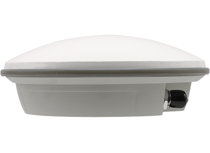
Harxon has launched a high-precision GNSS antenna, the HX-CSX633A. The HX-CSX633A has an upgraded architecture for more durable use and more flexible installations, making it suitable for agricultural vehicles, small robots and surveying applications.
Photo: Harxon
The HX-CSX633A features a durable, future-proof design with an IP67 waterproof housing. It meets MIL-STD-810-H for vibration and shock, increasing robustness for use under high-vibration conditions. The HX-CSX633A supports flexible installations including magnetic mount, screw mount and pole mount. Consequently, integrators can be confident this powerful antenna can be used in system designs for years to come, the company said.
The HX-CSX633A is fully functional, powerful and stable. The phase center remains constant with a multi-point feeding design. The ability to receive low-elevation signals with high gain and wide beamwidth makes it suitable for tracking visible satellites in tough environments, Harxon said.
The antenna’s low-noise amplification (LNA) features excellent out-of-band rejection, which can suppress electromagnetic interference and prevent disconnection when receivers are operated in complex electromagnetic environments.
Key Features of the HX-CSX633A:
supports GPS, GLONASS, Galileo, BDS, QZSS, IRNSS and SBAS signal reception
stable phase center guarantees positioning accuracy within the millimeter-level
strong anti-interference ability to endure challenging operating environments
Burkhard Boeckem and a Boston Dynamics robot dog share insights into smart digital realities. (Photo: Hexagon)
At HxGN LIVE Global 2022, in-person attendees experienced the full breadth of what the flagship conference has to offer for the first time since 2019. The conference is taking place this week at the Venetian hotel in Las Vegas.
Tuesday began with a keynote address by Burkhard Boeckem, chief technology officer, who discussed the importance of smart digital realities and their role in the potential of the metaverse to impact and enhance the physical world. Hexagon’s technology platform Xalt enables intelligence at scale. By integrating sensors and data integration across systems and solutions, like the BLK series and HxDR, Xalt provides the next level of connectivity to harness and utilize data for autonomous systems.
Summit-specific keynotes by speakers from Hexagon, its partners and sponsors provided expertise on issues, solutions and innovations shaping and reimagining various industries.
The Digital Innovation in Construction summit begins. (Photo: Hexagon)
Tuesday was also the first day of breakouts for all summits, with more than 100 sessions throughout the day covering everything from training and tips for Hexagon products to project success stories, panel discussions of industry trends, and a look at the precision engineering of Formula 1 cars with Hexagon partner Oracle Red Bull Racing. Sessions continue through the close of the conference on Thursday.
The Zone, the massive technology expo floor, officially opened for the first time this morning, where attendees explored some of the latest advancements, products and solutions available across seven summit-specific “islands” offering hands-on demonstrations and an opportunity to ask the questions that will help them make the best use of autonomous technology in their field.
Surveyors get the lay of the land at the Pure Surveying Island. (Photo: Hexagon)Advances in digital construction were provided by Leica Geosystems. (Photo: Hexagon)
In the evening, summit events took attendees around the grounds of the Venetian resort for various experiences.
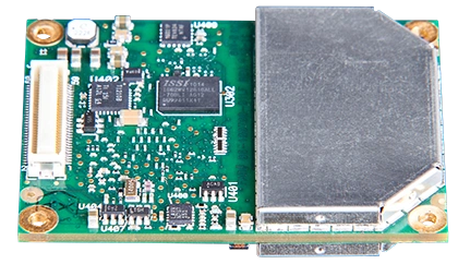
Topcon’s ultra-compact B111A GNSS receiver board can provide scalable positioning from sub-meter differential GPS to sub-centimeter real-time kinematic (RTK) positioning. The board’s flexible design — low power consumption, comprehensive communication interfaces and peripheral support — make it easy to integrate the B111A into any precise positioning application, Topcon said.
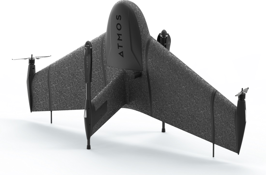
Besides in surveying and mapping, survey drones are now used in a broad spectrum of applications ranging from construction and mining to agriculture and environmental monitoring.
The Atmos Marlyn Cobalt is a vertical-takeoff-and-landing (VTOL) fixed-wing mapping drone developed by Atmos with the goal of allowing users to effortlessly collect accurate geospatial information and turn it into actionable insights. “Our mission is to provide professionals with the tool with which they can plan a better future with precision,” said Ruud Knoops, Atmos CEO.
To provide precise positioning accuracy, a GNSS board needs to compensate for inaccuracies caused by satellite constellations, receiver hardware and atmospheric conditions.
The use of Topnet Live — Topcon’s GNSS real-time correction service — provides high-accuracy positioning and survey-grade results to professionals through a 24/7 cross-border, consistent and reliable access. The combination removes the need for base stations, increasing efficiency leading to higher productivity and decreased costs.
Mason and Dixon were pioneers in bringing geodetic astronomy to the American colonies. Through the efforts of the Mason and Dixon Line Preservation Partnership, we can promote this scientific contribution along with the placement of the boundary stones.
Ask surveyors why they became engaged in the profession and why they had continued with it, most will centralize on one aspect: working outside. A career that allowed them to work outside in various environments, solving problems, and being part of a solution is typically the main answer they give.
Depending on the task at hand, a day in the field surveying can take one to several places, including urban/suburban neighborhoods, construction sites, and agricultural/wooded farmland.
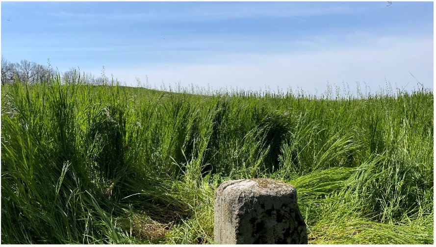
View from Mason Dixon Stone #95 looking toward Maryland. (Image: Tim Burch)
My entry into surveying was no different. From residential sites, condominium surveys, boundary and topographic surveys, and construction layout, my early years in surveying covered a lot of territory. While my career eventually took me out of the field and into an office managerial role, and now into leading a professional association, it does not erase the roots of one’s surveying knowledge and experience. Opportunities to be part of the field exercises of a survey, especially a boundary survey, are typically rare and subject to time constraints.
Having spent all my life in the flat topography of Illinois and surrounded by farm fields and urban sprawl, the ability to see for miles over the various horizons was the norm. Coupling these conditions with the Public Land Survey System (PLSS) and use of GNSS technology, it makes for a great environment for the professional surveyor to go about his or her work.
However, the United States covers many areas and contains distinct types of terrain, ecosystems and demographic groups that provide challenges to the surveyor. While I assumed moving from Illinois to the mid-Atlantic region would require adaptation, an opportunity to help retrace and inventory a significant part of American history provided me with an eye-opening experience. It also helped me appreciate the legacy of our surveying forefathers.
A small title dispute
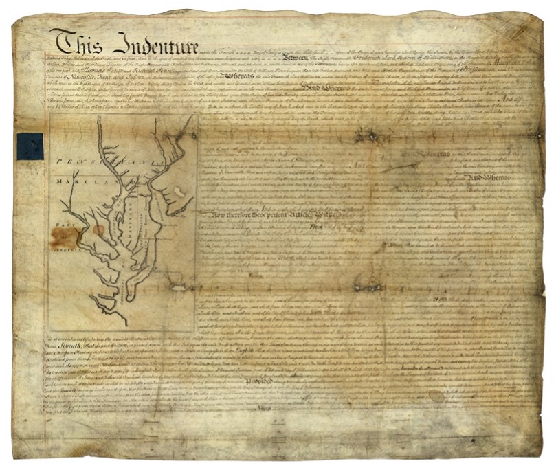
Even in the 17th and 18th centuries, disagreeing title descriptions to common lands was an issue. Reviewing two conflicting legal descriptions describing adjacent land boundaries is the basis of this survey exercise, and thus began a symbolic establishment of a famous boundary line that would lead to political and demographic ramifications in later years.
Here is the situation:
1632: King Charles I grants to Cecilius Calvert (second Lord Baltimore), a royal charter for establishing a new colony north of Virginia to a point “which lieth under the Fortieth degree of north latitude” and westward to the source of the Potomac.
1681: King Charles II (eldest son of Charles I) grants William Penn a royal charter of land between 43° N and a line extending westward from “a Circle drawn at twelve miles distance from New Castle…” to “the beginning of the fortieth degree….”
1682: King Charles II grants to William Penn an additional grant in the Delaware peninsula, which Lord Baltimore claimed.
1685: King Charles II directed his Board of Trade and Plantations to issue an edict ordering that territory to be divide equally, the western half going to Baltimore. This order endorsed Calvert’s claim of a boundary line being 19 miles to the north and providing him claim to Philadelphia. Part of the edict placed a burden on Calvert of providing a survey to authenticate the claim, but the survey was not completed. The boundary would eventually be established 19 miles to the south.
1731-1732: Charles Calvert, the fifth Lord Baltimore, petitioned King George II for help in demarcating the final boundary. He agreed on the final boundaries; however, a commission created to study the legal claims failed to deliver instructions in which a survey would be based upon. Calvert disputed its interpretation and refused to implement the arrangements.
1730s: Ongoing conflict over the disputed land claimed by both people from Pennsylvania and Maryland resulted in Cresap’s War, named after the land agent, Thomas Cresap, hired by Calvert to settle new development. In 1736, Cresap was accused of murder, arrested by Pennsylvania officials and his housed burned was burned down.
1750: After years of bitter controversy, British Lord Chancellor Hardwicke ruled that the southern boundary of Pennsylvania should be a line running westward from the point at which the line dividing the Delaware peninsula was tangential to a circle with a radius of 12 miles from the center of Newcastle.
After 100+ years of boundary disputes and deadly confrontations, in 1760 Frederick Calvert was directed by the English monarch to accept the terms of the 1732 treaty.
Penn-Calvert Land Grant Agreement. (Image: National Archives)
The unfilled challenge, however, was to commission a survey to establish the terms of the agreed-upon boundary. Given that the final location of the Pennsylvania/Maryland border was geographically based (approximate latitude of N 39°43’20”), the surveyors chosen to establish this line would have to be knowledgeable in such calculations.
Finding qualified surveyors in the colonies turned into a bigger challenge than first considered, so the monarchy assigned two surveyors from the Royal Society (full name: Royal Society of London for Improving Natural Knowledge). Enter Jeremiah Dixon (surveyor) and Charles Mason (astronomer) — the field party charged with tackling this monumental deed.
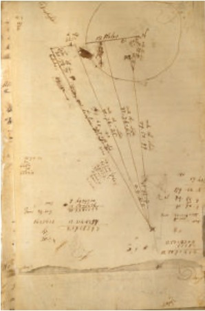
The survey calculations of Charles Mason. (Image: National Archives)
We know them by name for the lines they established in fulfilling the requirements of the boundary agreement, but how they accomplished their task remains a mystery to most. Previous exercises using geographical position determination was used in the sailing and shipping industries with lesser degrees of accuracy. This assignment would require higher levels of accuracy and precision, hence the reason for calling upon Dixon and Mason for the task.
By using geodetic astronomy, they were able to determine accurate (for the period) geographical positions of latitude. Geodetic astronomy is the art and science for determining, by astronomical observations, the positions of points on the earth and the azimuths of the geodetic lines connecting such points. It relies on spherical astronomy, using calculations and techniques developed by the Greeks in the second century A.D.
Besides the knowledge of performing the necessary calculations, the duo would also need to possess instruments to gather the accurate astronomical information. The survey of the agreed-upon line was to be established upon a constant line of latitude. The survey procedures would require turning angles (azimuths) from their meridian westwardly with accuracy not yet utilized in the New World.
Both instruments used for the project were built by John Bird, a well-respected instrument maker in London. The equipment consisted of a zenith sector, capable of measuring to two arc seconds. No field azimuth instrument of this accuracy existed in that era. They also brought a converted telescope/level set up for surveying purposes. This transit has no divided horizontal “plate,” only a tangent screw for slow azimuth motion.
In addition to the instruments and astronomical tables from Greenwich and Paris, the duo relied on a highly precise clock for marking time by the second, which was quite advanced for the period.
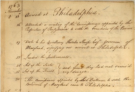
Dixon and Mason spent the better part of 1766-67 establishing the agreed-upon line using astronomy via the Bird instruments and taking copious notes documenting their calculations and survey conditions.
Field notes from Jeremiah Dixon. (Image: National Archives)
The markers set along the way —stone monuments chiseled back in England with demarcations — were quite accurately established despite the primitive nature of equipment and methodology for the survey. Mason and Dixon laid out the 233-mile long “West Line” in short segments, following the latitude arc of approximately N39°43’20” for 233 miles westward.
Old line versus new technology
In 2020, the Maryland Geological Survey (MGS) and the Pennsylvania Historical & Museum Commission (PHMC), members of the Mason and Dixon Line Preservation Partnership, began a new initiative to inventory these historic markers and submit them for inclusion into the National Registry. If accepted, the monuments will be part of a program established to help protect and preserve these physical boundary markers that define the boundary between the two states.
Part of the inventory has been the recovery and position confirmation by volunteer surveyors from the Maryland Society of Surveyors (MSS) and the Pennsylvania Society of Land Surveyors (PSLS). Using a geographic information system (GIS) app designed and implemented by the Maryland Geological Survey (MGS), volunteer retracers capture significant attributes about each monument.
While reestablishing the latitude/longitude of the recovered monuments with a smartphone or handheld GPS receiver is sufficient, several volunteers have used high-accuracy surveying equipment to determine a monument’s position.
Incredibly, the variation in the location of a given monument is well within reasonable tolerances from the originally intended installation. Also, because of GNSS technology, we now know more about continental drift. Because of this additional knowledge, 250+ years of tectonic plate movement should be considered when making these positional comparisons.
It should be noted that these monuments are a critical component of the boundary between states, and therefore must be considered senior to many other survey corners set after them. We cannot get lost in the sentimental aspect of recovering the monuments and not acknowledge the fact these points are the gospel when it comes to defining these state boundaries.
A Midwesterner in a ‘foreign’ land
My surveying career, as noted above, was solely in a state that is 200 years old, based upon the PLSS, and does not carry the history of the Mason-Dixon era of line establishment. So, when I was presented with the opportunity to join fellow surveying professionals from Maryland and Pennsylvania in recovering Mason-Dixon monuments for the inventory, I found it an easy event to join.
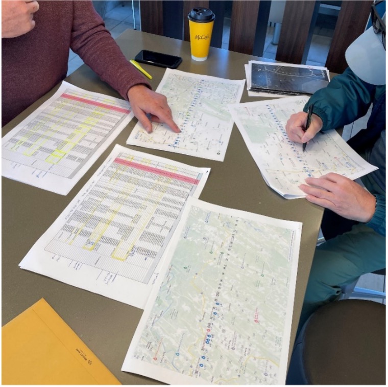
The planned meeting spot was a local fast food place at 8 a.m. on a sunny Saturday. Being it was in a small town, there were several groups meeting for their normal Saturday coffee klatches. Hearing a group mention “surveying,” I found my opening to identify myself as a fellow surveyor. After opening pleasantries, we settled into a game plan for recovering the targeted monuments for the day.
Planning a day of stone monument recovery along the Mason-Dixon line. (Photo: Tim Burch)
We settled on our assignments and enthusiastically went about our way. My partner for the day was Eric Gladhill, a Pennsylvania professional surveyor and veteran of Mason-Dixon monument retracement. In addition to his volunteer work, he has also authored several articles and a book on his surveying experiences, so it was quickly evident that we were in for a good day.
The first monument was not difficult to get to, and seeing it nearly brought a tear to my eye. Here before me was my first sighting of a Mason-Dixon monument stone, and it was simply amazing. Standing there admiring this 250+ year old stone, hand cut and carved in England and brought here by ship to be specifically placed on this line, I could not help but realize the importance of this monument.
This line, and these stones, were the culmination of two land grants that disagreed with each other more than 400 years ago. We were standing in the same location as a large survey party once did, where they observed the stars to determine an accurate position and directed axmen to clear the untamed forest to establish this important line. While it was a warm and sunny day, it gave me a chill to know we were following in the footsteps of our surveying forefathers.
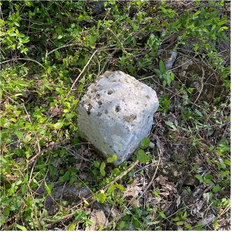
Mason Dixon Stone #98 – My first recovery! (Photo: Tim Burch)
We continued our way and recovered six more monuments, including a crown stone. Crown stones were placed at 5-mile intervals. The detail in the carvings for most of the monuments was noticeably clear, and is a testament to the craftsmanship of the era’s stonecutters.
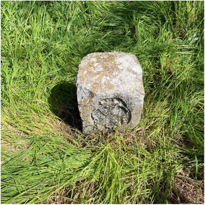
Mason Dixon Stone #95, a crown stone. (Photo: Tim Burch)
While locating these historic monuments, were felt we were standing on hallowed ground. The location of this line was important enough that people, both indigenous and settlers, fought for the right to build their lives there.
This was also a line that would be the site of many battles during the Civil War. Observing these monuments drove home the fact that surveyors play important roles in establishing land ownership both today as well as almost 300 years ago.
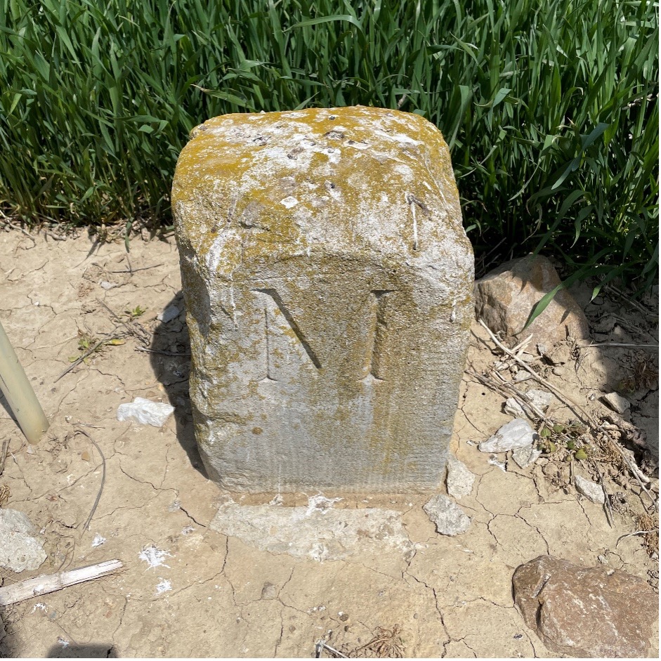
Mason Dixon Stone #93, a Maryland side marking. (Photo: Tim Burch)
Mason and Dixon were pioneers in bringing geodetic astronomy to the American colonies. Their work has provided inspiration for future generations of geospatial professionals, yet most of the public does not know about that portion of their contribution. Hopefully, through the efforts of the “Mason and Dixon Line Preservation Partnership,” we can promote this scientific contribution of Mason and Dixon along with the placement of the boundary stones.
My heartfelt thanks go out to Eric along with Wayne Aubertin and Rob Kundrick (Appalachian Chapter of the Maryland Society of Surveyors) for allowing me to join them for this task. They gave me a chance to be a true surveyor again and connect the past with the future.
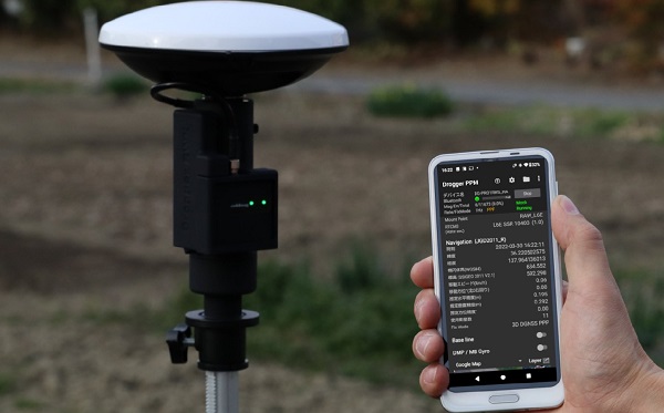
BizStation, a database company based in Japan, and u-blox have announced a highly accurate, compact and low-cost high-precision positioning solution for markets in East Asia and Oceania.
Featuring two u-blox modules, the solution delivers centimeter-level positioning accuracy where mobile network service is unavailable, including in maritime offshore surveying, agricultural and industrial vehicle guidance, and UAVs.
BizStation’s precise point positioning (PPP) system covers all territories served by Japan’s Quasi-Zenith Satellite System (QZSS) MADOCA correction service.
The solution leverages the strengths of two u-blox components. The first, a u-blox ZED-F9P multi-band high precision GNSS receiver module, is at the heart of BizStation’s DG-PRO1RWS GNSS receiver.
The second, a u-blox NEO-D9C correction-data receiver module specific to Japan, enables their virtual reference station to receive data on the QZSS L6E-band used by MADOCA.
The PPM (PPP positioning by MADOCA) Android application developed by BizStation then determines the location of the tracked device using the high-precision positioning data transferred via Wi-Fi from BizStation’s DG-PRO1RWS GNSS receiver as well as GNSS correction data from the virtual reference station. The PPM application performs all required calculations using the MADOCA positioning library developed by NEC Solution Innovators Co., Ltd.
The high-precision GNSS solution can be deployed either using a static or a mobile virtual reference station for a wide range of applications such as agriculture, drones, motor sports or surveying systems.
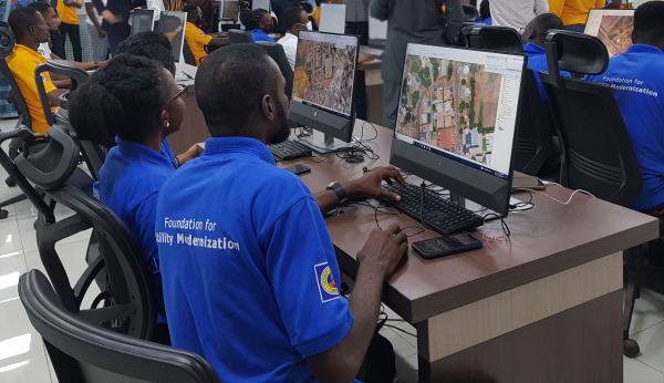
Hexagon’s Safety, Infrastructure & Geospatial division successfully deployed an advanced utility geographic enterprise asset management (EAM) system for the Electricity Company of Ghana (ECG). The smart EAM, featuring Hexagon’s G/Technology, will allow ECG to plan, manage and efficiently operate its distribution network to meet the growing needs of 4.5 million customers.
The enterprise system from Hexagon unifies data from a variety of geographic information systems (GIS), enabling bi-directional data flow with other systems based on the Common Information Model (CIM) standard. The system enhances ECG’s ability to geographically reference and manage assets with integrated tools for data surveying, capture and maintenance and network planning and calculation.
Mobile capabilities enable efficient inspections and maintenance, while a web portal assists employees with locating assets, reviewing the network and more. Migrating to Hexagon’s system will increase process efficiency and reduce asset-management costs by harmonizing systems, validating existing data and capturing missing data.
“The utility GIS is the critical component that fuels innovation in the utility,” said Keli Gadzekpo, board chairman of ECG. “This project is the foundation and the first step to modernizing ECG operations. It is the platform for digitization of electrical network assets, a prerequisite for bringing efficiency in the wire business.”
Photo: Hexagon
Part of ECG’s Modernizing Utility Operations Activity, the project was commissioned by Millennium Development Authority (MiDA), Ghana, on behalf of the Government of Ghana’s Millennium Challenge Account Entity Program and funded by the U.S. government.
“We are exceedingly grateful to Hexagon for working tirelessly to deliver this innovative product,” said Julius K. Kpekpena, Ag CEO and COO, Millennium Development Authority. “The technology sets Ghana’s biggest electric distribution utility on the path to modernizing its operations. The GIS is the foundation for modern tools to help ECG plan its networks, reduce losses, collect revenues and serve customers more efficiently.”
The project included procurement and installation of system software, server hardware, mobile field units and services for data migration by Hexagon, field validation of assets by PDSA Ghana (part of Hexagon), and production of aerial imagery by ILV Wagner using Hexagon’s Leica Geosystems surveying and airborne imaging technologies.
“Reliable electricity requires accurate data and tools to plan, design and manage networks, which can also reduce overall maintenance costs,” said Maximillian Weber, senior vice president, Global Utilities & Communications, Hexagon’s Safety, Infrastructure & Geospatial division. “We are proud to support Electricity Company of Ghana in delivering quality service to its customers.”
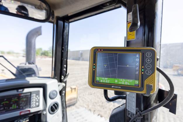
Topcon Positioning Group has announced its MC-Max machine control solution. Based on its MC-X machine control platform, and backed by Sitelink3D — the company’s real-time, cloud-based data management ecosystem — MC-Max is a scalable solution for mixed-fleet heavy equipment environments. It is designed to adapt to owners’ machine control and data integration needs as their fleets and workflows expand.
MC-Max increases processing power, speed, accuracy, versatility and reliability; and can be installed on a full range of dozers and excavators, using the same basic modular components. Modern, redesigned user and product interfaces were developed based on real-world applications and customer feedback and provide a simplified and immersive user experience that allows operators to learn the system easily.
“With MC-Max, we’ve created a solution that is flexible and can continue to grow as a contractor’s needs and capabilities expand,” said Jamie Williamson, executive vice president, Topcon Positioning Group. “This new solution provides improved scalability and precision in the field and offers business owners real-time data integration, connectivity and resource management capabilities across their entire workflow.”
The MC-Max solution offers flexible mounting solutions, as well as optional automatic blade and bucket control for a variety of machines. The system also provides a full battery of positioning technologies ranging from slope control to laser, multi-constellation GNSS, robotic total station and millimeter GPS systems.
MC-Max provides project managers a real-time view of machine positions, activities and onsite progress, and is compatible with a wide range of site communications systems.
Topcon MC-X Platform
The Topcon MC-X Platform is designed to make machine control easy to use and affordable for all contractors. The platform ties together mixed fleets by interacting with multiple versions of 3D-MC, providing connectivity to Sitelink3D and taking advantage of the multi-constellation capabilities of GNSS antennas.
A module for SurvCE version 6 software enables surveying with mixed brands of GNSS receivers and total stations. SurvCE is a data-collection software package from Carlson Software. SurvPC Hybrid + provides driver support for numerous devices, allowing the surveyor to interface with both types.
Features of SurvPC Hybrid+ include:
Follow Me. An alternative to optical tracking, Follow Me continuously turns the total station towards the prism using the location as determined using GNSS. This eliminates stray reflectors and lengthy searches.
Smart Lock. The software will automatically detect when a user is slowing to take a measurement and lock on the prism so that it’s ready to go.
Smart Staking. With smart staking, it will no longer be necessary to maintain optical tracking during stakeout. Stakeout directions are kept fresh using the GNSS receiver as the surveyor approaches a stakeout point. When close to the point, the total station will automatically turn and lock on the prism for the final staking precision needed.
Cross Check. SurvCE will automatically cross-check the total station and positions determined using GNSS and warn the surveyor when they differ.
Backup Tracking. With backup tracking, SurvCE will automatically show the position determined using GNSS on the map when the total station isn’t locked.
Hybrid-Resection. Easy hybrid-resection allows for setup anywhere using positions determined using GNSS to calculate the total station occupied point and orientation. Measurements from the GPS and total station are time-synchronized for an accurate and simple one-tap resection measurement.
Auto-Localize. Simplify setup by seamlessly auto-localizing the GPS receiver as total-station points are stored.
Easy Setup Wizard. The easy setup wizard walks users through setup using auto-localization, hybrid resection or hybrid localization, then finishes with a cross-check for quick project start.
The Autel Robotics Dragonfish Lite and Pro UAVs are now available in the United States, joining the Dragonfish Standard and providing more options and choices for UAV pilots.
The rugged Dragonfish UAVs are capable of vertical takeoff and landing (VTOL) with both multi-rotor and winged flight, with an endurance of up to 180 minutes. They are suitable for professional applications such as energy, mining, defense and surveillance. Maximum winged flight speed is 30 m/s (108 km/h, 67 mph), and maximum video transmission range is 30 km (18.6 miles) with a base station.
The 1-tap take-off and landing capability point-and-click user interface, and other smart autonomous features make the Dragonish simple for anyone to operate, according to maker Autel Robotics. The aircraft can make a smart decision to either land or return to base in case of issues such as loss of GPS signal, loss of operator communications, or low battery power.
The Dragonfish tilt-rotor system will automatically transition to multi-rotor mode if adverse conditions cause fixed-winged flight to stall or become unsustainable. The Dragonfish battery, barometer, positioning system, compass and inertial measurement unit all have backup modules to ensure flight safety.
Dragonfish UAVs can carry a variety of payloads, including standard high-resolution cameras, 50x optical zoom cameras, 12-megapixel wide-angle cameras, 1280 x 1024 high-resolution infrared cameras, and laser rangefinders for various imaging, surveillance and mapping tasks.
All Dragonfish UAVs are built from tough carbon-fiber and fiber-glass composite, providing excellent IP43 wind and weather resistance. Despite the strong construction, these aircraft are designed to be easily disassembled for space-saving transport. They can be assembled in three minutes without tools. Disassembled, Dragonfish fits in the back of any car or SUV.
The larger Dragonfish Pro provides the longest flight time of the series, 180 minutes with payload, and has a 6,000-m (19,685-ft) flight ceiling, making it suitable for applications such as discreet long-endurance surveillance and wide-area mapping. The maximum payload capacity is 2.5 kg.
Compact and lightweight at 4.5 kg (including two batteries) with a 1,600-mm wingspan, the Dragonfish Lite can carry a 1-kg payload up to its service ceiling of 4,000 m, and has 75 minutes’ flight endurance.
Dragonfish Standard is already available. Dragonfish Lite and Dragonfish Pro will be available in the U.S. starting in April.
Firmware Release
The company also announced that pilots of Autel Robotics’ EVO Nano and EVO Lite series drones can download a firmware update that adds features including Dynamic Track 2.1 (person only), SuperDownload, 8-bit Log video, HDR video and other improvements. Some of these new firmware features are available now for selected models, and other features will become available for the EVO Lite, Lite+, Nano and Nano+ series in the near future.
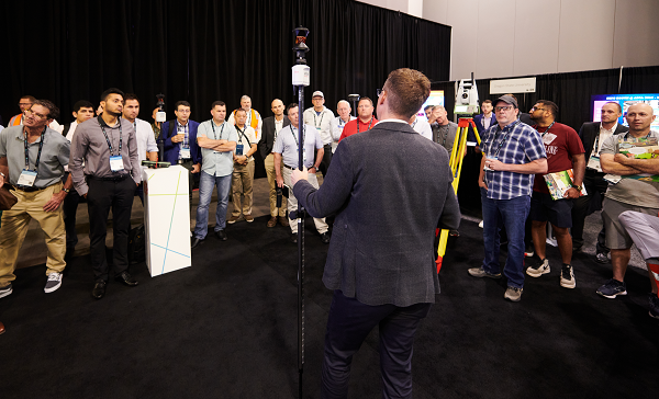
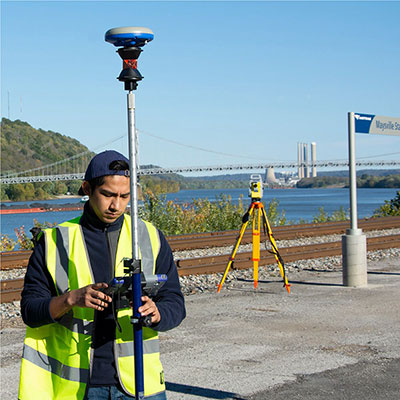
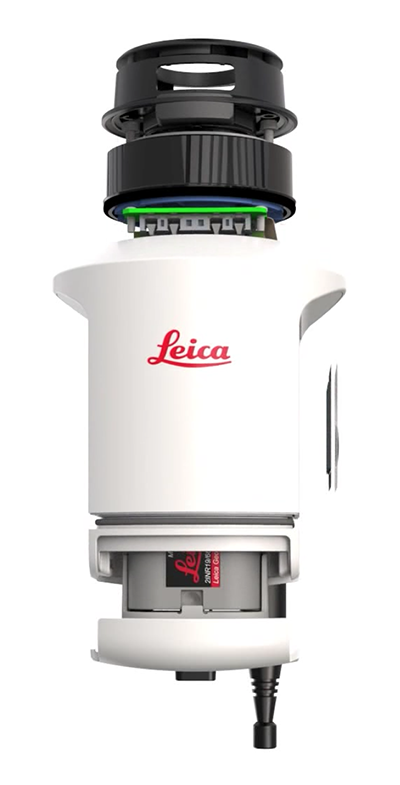
Leica Geosystems, part of Hexagon, has introduced the Leica AP20 AutoPole — a solution for automated total stations that boosts productivity with tilt compensation, automatic pole-height readings and unique target identification.
The AP20 AutoPole combines an intelligent sensor module with the new AP Reflector Pole and operates with Leica Geosystems’ existing automated total stations to create a solution for autonomous workflows.
It is designed to solve three workflow challenges:
holding the pole vertical and stable
entering the pole height manually into the field software
locking to a foreign target on a site with multiple reflectors.
The tilt compensation of the AP20 AutoPole increases efficiency when working with total stations. It is no longer necessary to level the pole for measurements and stakeout. Tilt compensation decreases measurement time and increases flexibility and safety on site by enabling the measuring of points in locations that are inaccessible or put the user at risk. By updating the pole height automatically in the field software, the system ensures that the height on record is always correct, which avoids errors, time-consuming postprocessing and returning to the field to remeasure.
Additionally, the AP20 AutoPole’s target identification ensures the user’s instrument will always lock to the correct target.
“At Leica Geosystems, we understand that tight time schedules, growing expectations for accurate on-demand data and budget constraints put a lot of pressure on surveyors and construction professionals,” said Hans-Martin Zogg, business director, Total Stations, Leica Geosystems. “The AP20 AutoPole is a game changer because it solves several challenges simultaneously. Its tilt compensation and automatic pole height readings are absolutely unique in the industry and will transform how professionals measure with total stations.“
“As a surveying company, the only way we can stay competitive and profitable is to acquire spatial data simply, quickly and efficiently,” said Clifton Webb, director of Warner Surveys. “The Leica AP20 helps us stay ahead of the curve by increasing our productivity and flexibility. It allows us to measure points that were impractical or unsafe to measure before.”
Advanced Navigation has launched a new fiber-optic gyroscope inertial navigation system (INS), named Boreas. It is an ultra-high accuracy, strategic-grade INS, offering a reduction in size, weight, power and cost. Boreas is the first product to be released based on Advanced Navigation’s new DFOG (digital fiber-optic gyroscope) technology, which is the culmination of 25 years of development involving two research institutions.
The Boreas is targeted at applications requiring always-available, ultra-high accuracy orientation and navigation including marine, surveying, subsea, aerospace, robotics and space.
“Boreas is the first product on the market to offer our patent-pending DFOG technology,” said Advanced Navigation CEO Xavier Orr. “DFOG represents a step-change for fiber-optic gyroscopes. With Boreas’ ultra-high-accuracy and strategic-grade performance combined with the reduction of size, weight, power and cost by 40%, we will be able to enable new industries and applications that were never possible before.”
The Boreas delivers strategic-grade bias stability of 0.001 deg/hr. This allows it to achieve ultra-high roll/pitch accuracy of 0.005 degrees and heading accuracy of 0.006 degrees. Boreas allows for full independence from GPS with dead-reckoning accuracy of 0.01% distance traveled with an odometer or Doppler velocity log.
The Boreas features ultra-fast gyro compassing, taking only 2 minutes to acquire heading in both stationary environments or on the move. Gyro compassing allows the system to determine a highly accurate heading of 0.01 degrees secant latitude without relying on magnetic heading or GPS.
The Boreas contains Advanced Navigation’s sensor-fusion algorithm, which is more intelligent than the typical extended Kalman filter. The algorithm is able to extract significantly more information from the data by making use of human-inspired artificial intelligence. It was designed for control applications, with a high level of health monitoring and instability prevention to ensure stable and reliable data.
Advanced Navigation designed Boreas from the ground up for reliability and availability. Both the hardware and software are designed and tested to safety standards, and it has been environmentally tested to mil standards.
The system is designed for a mean time between failures of 500,000 hours. Additional features include Ethernet, CAN and NMEA protocols, as well as a disciplined timing server providing PTP. An embedded web interface provides full access to all of the device’s internal functions and data. Internal storage allows for up to one year of data logging.
While some tasks for AEC surveying are similar to other types of surveying — such as original ground surveying, creating site control and live monitoring — the biggest differences and challenges arise in data management, timeframes, communication and deliverables.
In AEC surveying, the project timeline is the primary factor driving everything, creating a different kind of pressure on the surveyor. As data experts and problem solvers, surveyors for AEC must quickly adapt to construction progress, as their survey knowledge can be needed on site at any point.
Information transfer challenges also exist — such as clearly communicating data to non-surveyors who perform measurement tasks — along with creating unique deliverables across construction stages. These include 3D terrain models with real-world coordinates for architects; fit-for-purpose computer-aided design and Industry Foundation Class models for machine operators and mechanical, electrical and plumbing installers or off-site fabricators; and progress reports for project owners.
Several AEC firms have opted to create their own inhouse survey teams. This allows greater control over the consistency and clarity in communication and deliverables, because they focus exclusively on surveying for AEC and are therefore familiar with its specific challenges.
The main challenge for the surveyor in AEC is sifting through and processing the data, assessing quality, understanding relevance, producing results and crafting deliverables to meet the clients’ needs.
An integrated total solution is important for AEC surveyors who must decide not only which technology to use, but how to process data from different technologies together. Our products fit within this integrated solution concept.
Leica Geosystems‘ automated total stations, multistations and GNSS blend innovation and traditional technology, such as the Leica GS18 I with tilt and visual positioning, enabling surveyors to measure more, faster.
For mass data collection, the Leica RTC360 3D laser scanner operates at two million points per second and contains visual inertial system (VIS) technology simplifying the registration process. The Leica BLK series combines intelligence and accessibility, including the BLK360 imaging laser scanner, the handheld BLK2GO, and the latest autonomous technology of the BLK2FLY and BLKARC.
Finally, our software connects surveyors to their sensors and data in the field with Leica Captivate and Leica Cyclone Field 360 and to the office with Leica Infinity and Leica Cyclone, extending to existing CAD software with the Leica CloudWorx suite of CAD plug-ins.
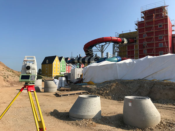
Bringing an Aqua Park to Life
One memorable success story was the use of our products for AEC survey tasks during construction of Germany’s biggest aqua park, Rulantica. The survey work was led by Saladin Keller of Keller planen + bauen. The project involved the creation and construction of a Nordic-themed water world featuring 25 attractions, including water slides, a wave pool and a lazy river.
Alongside all the typical surveying for AEC tasks — establishing site control, staking out pipes, and planning and staking the entire traffic infrastructure — Keller had the challenge of measuring and positioning the complex internal geometry. These tasks required skilled surveyors and a variety of survey tools, such as total stations, GNSS rovers, laser scanners and powerful processing software.
Operating within the AEC environment also meant that communication and flexibility were key to the success of the project. Keller needed to provide the right data to different trades and handle urgent maintenance requests requiring surveying skill, such as rebuilding parts and adjusting utilities.