A point cloud is fundamentally a simple construct. It is a collection of points in 3D space, each point being given a coordinate in Cartesian convention. The points can also be given other properties, often these will be indicative of how they were obtained.
Examples might include the time at which they were “seen” by the surveying device that collected the data. The intensity or error in position that the point has might also be included.
Often point clouds will have around 100 million points after conducting a survey. Photography can also be overlaid on point clouds using photogrammetry techniques to essentially build 3D photography.
Image: OxTS
INS survey: point clouds
The principal method of collecting point-cloud data is by using lidar. Lidar technology is akin to radar: light is sent out from the device and bounces back off of objects. The difference is that radio uses large wavelength radio waves and lidar uses small wavelength lasers for high precision.
The time for light to return to the device is used with the speed of light to calculate the distance away. Typically, a lidar device will contain lasers with a fixed vertical angle, but which spin around in the horizontal plane. Internally, the device knows at what angle the laser is pointing vertically and its azimuth angle. This gives the device the position of the point on the object in 3D spherical coordinates.
The lasers inside produce thousands of points per second. Intensity, mentioned above, refers to the intensity of the reflected beam and indicates the reflectivity of the object.
What is a georeferenced point cloud?
Lidar requires navigation data to conduct a survey. We combine the navigation data with the lidar data to create georeferenced point clouds. Lidar devices know where points are in relation to each other, but they need to be told where they are in the world to be able to build a point cloud while moving the lidar.
The navigation data often comes from an inertial navigation system (INS). An INS is a sophisticated combiner of inertial measurement unit (IMU) and GNSS data to get the best navigation data — so a device knows where it is in the world and how it is moving.
The coordinates from the INS are added vectorially to the point coordinates of the lidar to get the final coordinates that would be used in the point cloud. This allows a user to put their lidar device on a vehicle like a van or an unmanned aerial vehicle (UAV) with an INS, to survey large areas efficiently instead of doing multiple static surveys and stitching them together.
Photo: OxTS
What are point clouds used for?
There are a wide range of applications for which point clouds can be used. They are increasingly used in real time for robots and autonomous driving computers to understand their environment and navigate through it. The data in a point clouds is convenient for recognizing and identifying surfaces and objects; for example, other cars, road signs and lane markings.
OxTS has been a global leader in inertial and GNSS technologies since 1998. OxTS is fundamentally involved in helping car manufacturers get the navigation data they require to go with lidar data in autonomous vehicle development, and in point clouds creation for use in surveying.
Distances and volumes are easy to calculate using point-cloud analysis software, and intensity can help identify different materials.
Another feature that lidar offers is multi-returns. This allows a laser pulse (which has a finite cross-section) to bounce back off of multiple surfaces to give multiple points from the same pulse. This is particularly useful for seeing windows and also seeing through them, and also for a myriad of other uses such as seeing the top of a treeline and the ground when flying over with a UAV.
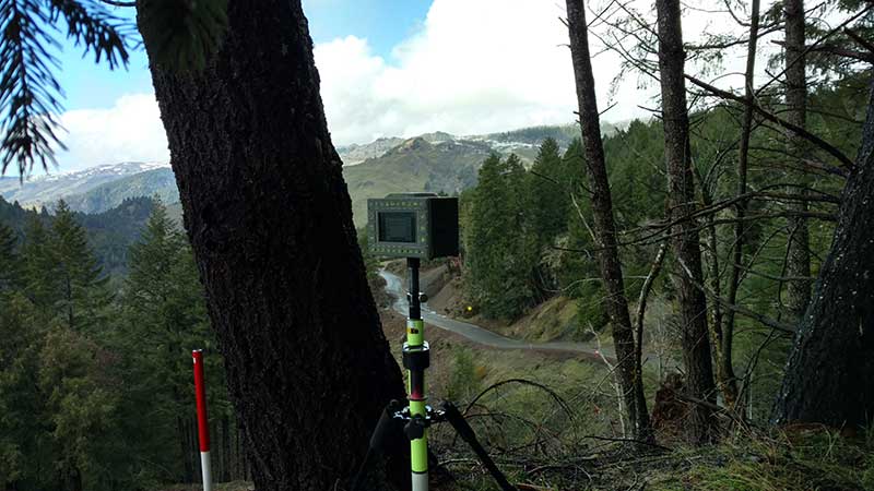
It can also be used to see snow depth. The lidar can see the top layer of snow and also gets another strong return from the ground beneath.
At OxTS, we see lidar point clouds being used for driverless-car and work-vehicle development, coastal and forest management, infrastructure monitoring (signs, drains, bridges, road surfaces, railroads, etc.), creating 3D models of cities, pipeline exploration and more.
The final product is a simple file format, for which the possibilities are almost endless — and we see new applications using point clouds all the time.
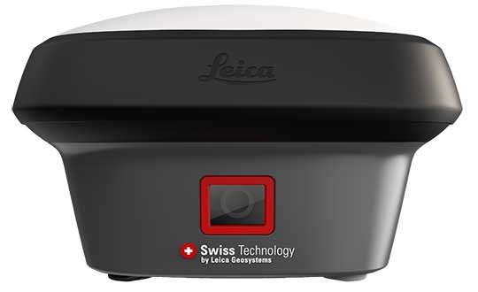
Hexagon AB has introduced the Leica GS18 I, a versatile, survey-grade GNSS RTK rover so powerful it enables surveyors to measure what they see, even structure in difficult-to-reach places, the company said.
It comes equipped with all the innovative functionality of the Leica GS18 T — Hexagon’s calibration-free, tilt-compensating GNSS solution immune to magnetic disturbances, plus the power of survey-grade visual positioning.
Through sensor fusion of GNSS, motion (IMU) and image (camera) technology, the Leica GS18 I enables the measurement of points from images. The ability to capture and measure sites via images goes far beyond the advantages of the GS18 T, which introduced the quick and convenient ability to measure points in spaces that cannot be measured with vertical poles, such as building corners, walls and points underneath obstacles (for instance, cars).
With the Leica GS18 I, professionals can now map areas that are difficult to reach physically, such as trenches, high power lines and busy roads, or blocked from GNSS signals, such as areas underneath bridges or canopies — safely and effortlessly from a distance.
“With the Leica GS18 I, mapping and surveying just got simpler, safer and more productive than ever before,” said Ola Rollén, Hexagon president and CEO. “The ability to quickly document an entire area of interest without the need to switch between tools or manoeuvre through obstacles frees up equipment and crews. Additionally, the simple and intuitive workflow of the Leica GS18 I brings the versatility of visual positioning to new user segments and applications — from utility service providers to crash scene investigators.”
The Leica GS18 I enables users to measure hundreds of points within minutes. Integration with Leica Captivate field software enables intuitive onsite point measurements and quality assurance from the field.
Further measurement of the captured images is supported by integration with Leica Infinity office software, which also enables the creation of automatically registered and referenced 3D point clouds from the images in standard export formats for use in a variety of point cloud software.
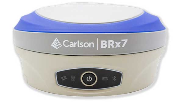
Carlson Software is now offering its next-generation multi-frequency, multi-GNSS BRx7 smart antenna.
The BRx7 is a full redesign of Carlson’s flagship GNSS receiver, delivering high-level specifications, performance and value for surveyors, contractors, engineers and GIS professionals.
Weighing 2.8 pounds with batteries, the BRx7 saves time and increases productivity by accurately compensating for tilt. It comes standard with dual, hot-swappable batteries for 11+ hours of uninterrupted efficiency. The BRx7 provides 800+ channels, 8gb of memory, and is designed with a rugged, compact IP67-rated housing.
Best-in-class RTK performance is provided by the Athena GNSS engine, supporting multi-frequency GPS, GLONASS, BeiDou, Galileo, QZSS, IRNSS and Atlas L-band capability. In addition, the BRx7 uses proprietary SureFix technology to provide a high-fidelity quality indicator of the RTK solution, allowing users an extremely high confidence in their current accuracy.
The BRx7 provides RTK baselines up to 50 km with fast acquisition times when used with Carlson Listen-Listen, as well as UHF, spread spectrum, cellular, Bluetooth and Wi-Fi wireless communication.
Well-suited to a variety of operating modes, the BRx7 can be deployed as a powerful base with additional access to BeiDou phase 3 satellites in a base-rover setup, or as a lightweight, powerful network rover.
“The BRx7 represents the next generation of GNSS technology,” said Butch Herter, Carlson’s director of hardware development. “Through this total redesign in partnership with our manufacturer, Hemisphere GNSS, we’ve brought the technology and functionality above the competition while retaining the ease-of-use, durability, and superior support that Carlson is known for.”
The smart antenna comes with a dual-band radio module that is capable of both 400 MHz and 900 MHz operation. This allows for the long range capability of the UHF 400 MHz signal plus the ability to switch to the 900 MHz frequency-hopping spread spectrum (FHSS) signal for better performance in noisy radio environments.
The BRx7 introduces a new INS-based sensor-fusion platform to support enhanced tilted pole measurements for land survey applications. This new design allows for easy calibration, is immune to magnetic interference, and is extremely reliable in virtually any environment.
“The BRx7 represents the advanced technology, durability, and ease-of-use that our customers have come to expect,” said Bruce Carlson, founder and president of Carlson Software. “By redesigning this system from the ground up, we are offering our customers both unparalleled performance and versatility, but also a value that’s unbeatable in the market today.”
The creed “Neither snow nor rain nor heat” may apply to postal workers, but it also could apply to land surveyors.
Today’s surveyors rely on GNSS as a critical tool to enable completion of their tasks, whether defining a property boundary or mapping mining drill sites.
In the articles that follow, surveyors share their success stories using the latest GNSS receivers, software and correction services, all of which are constantly improving to make their tasks easier — despite the terrain or weather conditions.
How one man triumphs
Adam Plumley is a one-man surveying shop in North Carolina. He also wears another hat as a sales, support and product development consultant to Javad GNSS.
“As a land surveyor, I use the equipment every day,” Plumley said. “Javad’s equipment has made it possible for me to operate solo.”
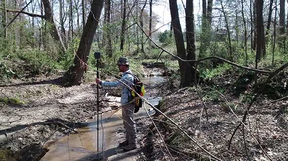
Photo: Stephen Drake
In the project pictured above, Plumley surveyed a 50-acre farm parcel to separate out the six-acre improved northeast corner. “I located the creek, building and improvements on the property east of the road and ran the lines to the creek on the west side of the road.”
The difficult locations on this 2016 survey were at the creeks. It took Plumley up to a half hour to locate the corners and creek points under the tree canopy.
“It would have taken much longer than it did if I had traversed the boundary conventionally,” he said, “not to mention I would have been much more tired at the end of the day.”
Instead, Plumley used a Javad GNSS Triumph LS and Triumph 2 base/rover system with corrections broadcast over the internet.
“I set up the Triumph 2 base about one mile away in an open yard with great sky view. It took me one day to do the initial recon and locations, and another couple of hours to set the new corners the next day,” he said.
Plumley has since upgraded his base receiver to another Triumph LS and added a J-Link 35-watt external radio to his toolbox.
“One thing this and other challenging surveys have taught me is to be patient. To obtain accurate results that you can be confident in takes time.”
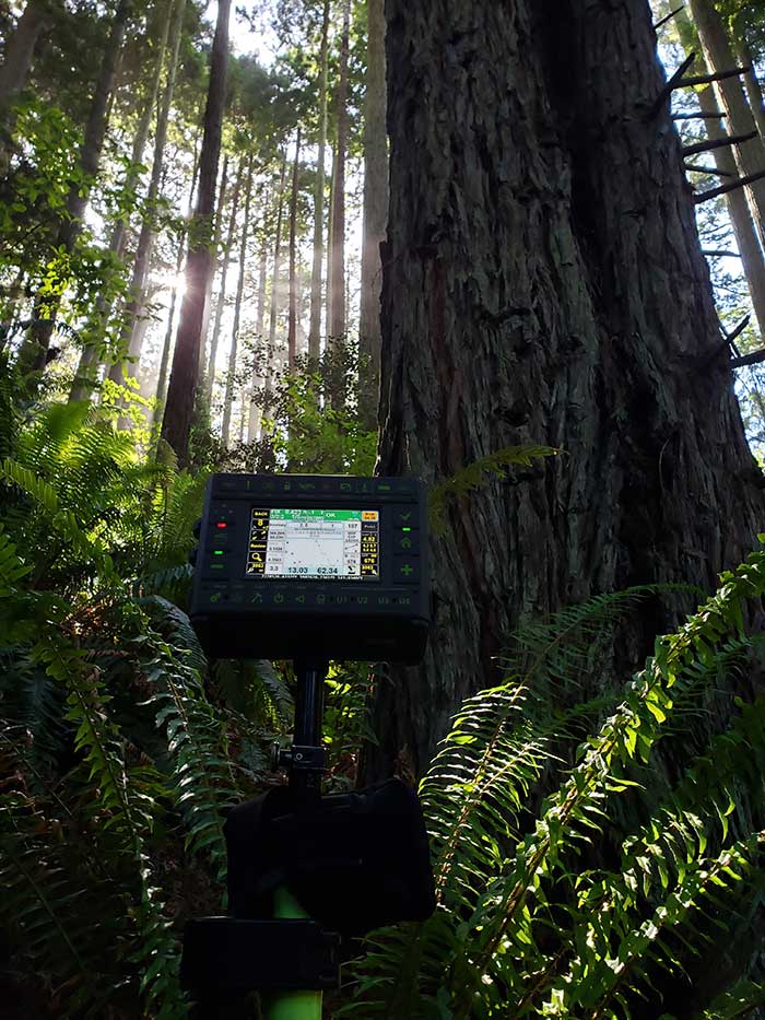
About our cover
Our cover photo this month was taken in June 2019 by surveyor Stephen Drake, near his home on the north coast of California. “These redwood forests and very rugged, remote coastal mountains can really test you,” he said. He was using his Javad Triumph-LS rover with the J-Field built-in surveying software, communicating to a Javad GNSS Triumph-2 base station attached to his house. A Verizon Jetpac mobile hotspot (in the black pack hanging below the Triumph-LS in the photo) picks up signals from his home router; the port-forwarded corrections are configured with Javad software.
Stephen calls this his standard configuration, but finds it very flexible. When he is more than 20 miles from home base, he relies on a Triumph-2 and a radio modem placed near the site. He can also use the California Real Time Network (CRTN) with the Jetpac.
He also relies on Javad’s Hybrid RTK, automated post-processing with Javad’s DPOS, automatically generated raw data and quality reports, and the many built-in indicators in J-Field that provide real-time feedback and “give me assurance on almost every measurement before I walk away from it,” he said.
The efficiency that his equipment provides has made Stephen valuable even to firms that already have in-house surveyors, he said. “I honestly do not think I would be here without Javad. It has been a true potent business partner.”
Helping the guard: For the Kentucky Air National Guard, Sibole surveyed for paint lines on the taxiway for C-130 aircraft. (Photo: Matt Sibole)
Like Adam Plumley, Matt Sibole is also a solo surveyor and a Javad GNSS advocate. Based in Kentucky, Sibole tackles up to 140 jobs a year, which he would be unable to do using only a total station or a robotic station. Instead, he relies on the accuracy of GNSS.
He particularly relies on J-Field, the Javad GNSS data-collection software. When using the software’s “Boundary Profile” feature, he can get a fix, then re-initialize and get another fix that he can then compare in real time to the previous fix.
“J-Field keeps all fixes in memory to compare to each other, until you get a group of fixes that agree with each other to verify which fix is the correct fix,” Sibole explained. “We all know that a fix is not necessarily the ‘right’ fix. Javad’s J-Field program will give the user the confidence to know in real time that the shot is correct.”
“J-Field also has a relative accuracy calculator built in to verify that I meet minimum standards in the field before I leave the site,” Sibole said.
Up to the challenge: In a nine-month project, Drake’s team used a Triumph-LS for slope-staking along a four-mile stretch of California’s SR 36 near Dinsmore. The federal project will realign and improve the deadly switchback single-lane curves of the mountain pass. (Photo: Stephen Drake)
In the mountains of Northern California, a dangerously twisting stretch of road — the site of numerous fatal accidents — is being widened and realigned. Because it passes through the Six Rivers National Forest, the Highway 36 project is managed by the Federal Highway Administration (FHWA) in partnership with Caltrans.
Surveyor Stephen Drake and his wife and business partner Mary Drake are using the Javad GNSS Triumph-LS to tackle the tricky assignment.
“We started this job in June 2017 shortly after founding Lost Coast Land Surveying,” Stephen explained.
“We ran slope staking and culvert cross-section/staking through about March 2018. We returned off and on to do topo mapping in areas that had landslides and other control surveys to support Mercer-Fraser [the construction contractor] grade-checking crews. We provided the control they calibrated their GPS systems to, based on the control we received from FHWA and Caltrans.”
Because of various troubles, such as landslides, the project is still a season from finishing, though the Drakes’ contribution is mostly complete.
The Drakes had tackled similar jobs, including on the Chiniak Highway near Kodiak, Alaska. Still, the task was daunting. The surveyors had to set catch points every 50 feet for four miles on both sides of the highway, 200 feet upslope and 100 feet downslope. “I have learned that the way to the end is one stake at a time, start, and keep going,” Stephen said.
The couple had to juggle home life with three boys with long days at the job site. Sometimes Mary had to remain home. “Usually I tried to hit more moderate slopes on those days,” Stephen said. “We bounced around the project a bit, some days only covering a 250-foot stretch because it was slow going scaling the slopes.”
The FHWA contracting officer, a veteran Federal Highways engineer, marveled at the efficiency of the modern surveying methods used by the Drakes, telling Stephen that two six-man crews used to be needed to accomplish what the couple could today.
“I will attribute a huge part of our efficiency to the Triumph-LS advantage,” Drake said, as well as the couple’s 20-year track record in environments as diverse as the Arctic, the Everglades and Arizona.
“During the course of the project we received a lot of comments from ‘I don’t know how you are doing this’ to ‘You are superhuman’ at one point,” Stephen said. “But it is just being tough, tenacious and Javad.”
All told, the surveyors set more than 2,000 stakes. “We got the toughest part of the job going for them,” Stephen said.
Hitec Commercial Drone Services expects to provide training, precision aerial missions and comprehensive data collection to a variety of industries, including
agriculture, construction, excavation, mining and aggregates, oil and gas, engineering and surveying, public safety and many other vertical sectors. Hitec maintains a fleet of unmanned vehicles. It offers proprietary mission-control software and data and photogrammetry collection techniques with its comprehensive unmanned aviation experience.
The new division’s field services director is Jim Bonnardel, an innovative entrepreneur with a history steeped in unmanned flight. Bonnardel established his own successful business in 1982, providing aerial services to business-to-business entities. His inventive nature and extensive flying prowess led him to become a certified and insured UAS service pilot and instructor.
Bonnardel has logged more than 1,750 precision mapping missions, inspected 2,000 utility structures, and flown more than 2,500 commercial and residential property shoots, as well as dozens of missions for creative projects involving both television and music videos.
He is also an instructor at Grossmont College in El Cajon, California. He has provided 850 hours of commercial instruction, as well as 550 hours of instructional field training and vetting for utility inspection crews. As a result of his training experience, Jim has issued 150 sUAS Utility Training Certificates.
Latest inertial navigation system serves new customer requirements in autonomous vehicles, mobile mapping, surveying and more
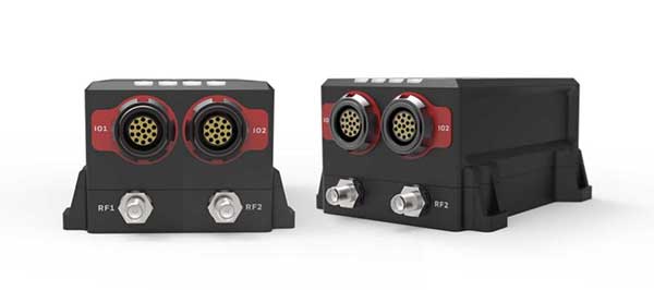
Photo: Honeywell
Honeywell is introducing the HGuide n380, an inertial navigation system (INS) that communicates position, orientation and velocity of an object — such as an autonomous vehicle or unmanned aerial vehicle (UAV) — even when global navigation satellite signals are unavailable.
Smaller, lighter and lower priced than previous Honeywell inertial navigation systems, the HGuide n380 is built using Honeywell’s rigorous design standards to withstand harsh environments in the air, on land or at sea.
“We recognized a need for a small, high-performance inertial navigation system in areas like 3D mapping, surveying and other applications where space is at a premium and performance cannot be compromised,” said Chris Lund, offering management senior director, Navigation and Sensors, Honeywell Aerospace. “We responded by developing the HGuide n380 inertial navigation system, which provides our customers with proven, cost effective inertial sensor technology, created for aerospace applications, but that can be integrated into almost any architecture.”
The new inertial navigation system is composed of Honeywell’s HGuide i300 inertial measurement unit (IMU), a GNSS receiver and Honeywell’s proprietary sensor-fusion software, which is based on the algorithms used for navigation on millions of aircraft every day.
Inputs from these components are fused together to determine position, orientation and velocity to deliver critical navigation information even in areas where a satellite signal is degraded or altogether unavailable, such as canyons, bridges, tunnels, mountains, parking garages or dense forests.
“As the industry evolves, Honeywell’s HGuide suite of IMUs and navigators will be a key enabler of emerging segments like autonomous vehicles, mobile mapping, precision agriculture, robotics and surveying,” Lund said.
During its development, the new product was placed in extreme environments to test ruggedness and was exposed to extensive factory calibration and compensation procedures that help ensure measurement accuracy and performance.
Honeywell has extensive experience in designing and building high-end inertial sensor and navigation systems and has used that expertise to develop a lower-cost portfolio of HGuide offerings to serve new markets and customer requirements.
To date, Honeywell has delivered more than half a million high-performance inertial sensors to serve as navigation aids on an extensive list of manned and unmanned vehicles, which include many air and spacecraft in use today.
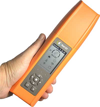
Bad Elf LLC has completed transition of all Bad Elf Flex receivers to the Hemisphere GNSS Phantom OEM module.
Photo: Bad Elf
As one of the first partners to incorporate the Phantom, Bad Elf Flex offers significantly enhanced capabilities and further exemplifies the company’s commitment to future-ready GNSS designs.
“We tested the Phantom OEM modules extensively, and confirmed they deliver the promised power savings and performance improvements when integrated with the Bad Elf Flex,” said Larry Fox, Bad Elf’s vice president of marketing and business development. “Hemisphere’s technology allows us to democratize GNSS through Bad Elf Flex.”
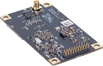
The new Phantom modules deliver a 30% gain in battery life, superior performance and scalable access to every GNSS constellation and signal, including GPS, Galileo, GLONASS, BeiDou, QZSS, IRNSS, SBAS and Hemisphere’s Atlas L-band, Fox said.
Photo: Hemisphere GNSS
Bad Elf Flex is a scalable-accuracy GNSS receiver with a daily option to choose between L-band and real-time kinematic (RTK). In standard configuration, it achieves 30-60 cm accuracy in real-time for GIS use.
Consuming a Bad Elf Flex Token unlocks a full RTK workflow for a 24-hour period to deliver 1-cm horizontal accuracy. Bad Elf Flex stores the tokens directly on the receiver, making them available for use anytime and anywhere. Customers requiring high accuracy at all times can purchase the Bad Elf Flex Extreme bundle, with RTK capabilities permanently unlocked, for a one-time upgrade fee.
Surveyors and their crews now have a scalable-accuracy, survey-grade receiver. GIS managers can focus on flexible field choices for work crews with varying skill levels. Bad Elf Flex falls within most capital expense budgets, allowing businesses to obtain operational and financial efficiencies.
“Bad Elf saw an opportunity to offer the GIS community a product lineup with better than 3-meter accuracy for under $3,000,” said John Cunningham, Bad Elf’s chief executive officer. “We began three years ago with our 2-meter ($300) and 1-meter ($600) mapping-grade product offerings. Our customers continued asking us to address the 50 cm, 10 cm and 1 cm requirements for their businesses. We worked hard over the past two years to build a platform, Bad Elf Flex ($3,000), that addresses these needs without breaking budgets. We have a solution that works today and provides a foundation to meet future customer requests. We love learning from our customers and look forward to continuing this conversation and extending high-accuracy GNSS for all.”
“Hemisphere is excited that Bad Elf’s Flex series now features our latest generation GNSS receiver,” said Miles Ware, director of marketing at Hemisphere. “We believe the scalable accuracy option made possible by our high-performance Atlas L-band correction service will be a game-changer in their served markets.”
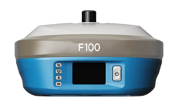
Geneq Inc.’s new F100 GNSS receiver, an upgrade to the F90, is designed to meet surveyors’ demands for high field performance, flexibility and cost-effectiveness.
The F100 tracks multiple constellations (GPS, GLONASS, Galileo, Beidou) and can maximize the acquisition and tracking process with all-in-view GNSS frequencies.
Another important feature from the F100 is the 1.45-inch color LCD display with a multi-touch capacitive screen. It has 32GB of internal memory. Its integrated second-generation web user interface control is compatible with all devices and all browsers.
Photo: Geneq
Providing maximum performance for accuracy and real-time measurements, F100 also supports real-time kinematic (RTK) correction services, including the RTX service that can get centimeter-level accuracy without a base station. The F100, with its advanced technology, ensures high performance even in difficult environments such as under heavy canopy.
The F100 has an excellent combination of GNSS, 4G, Bluetooth and Wi-Fi antenna. The innovative F100 has a built-in 5-watt radio that enables an effective baseline of 10 kilometers.
Its shorter charging time and a battery of 13600-mAh capacity enable long hours in the field. Even with its magnesium alloy casing, F100 weighs only 1.5 kg and measures 154 x 154 x 76 millimeters. Mobile field workers will find in this feature an ally to their surveying productivity.
With its integrated high-sensitive E-bubble and new tilt survey algorithm, the F100 becomes a calibration-free GNSS receiver. Immune to magnetic disturbance and free from limitation of tilt angles, the F100 can be used to measure unreachable points.
Everywhere we look, data is being collected, reviewed, analyzed and stored. It used to be that data was a static piece of information, like a piece of paper in a filing cabinet. Millions of pieces of data being created yet almost all of it never to be used again. The computer and electronic storage began a revolution of how we warehouse this information but that was only the beginning. Technology has turned data into a living, breathing beast few understand yet it controls most of our lives in various ways.
Mapping of the earth has not always been about establishing boundaries and parcels; many of the early maps and plats were created to depict the topography of our world. While there are some indications that Middle East maps depicted parcels, the first examples of topographic maps were created during the Roman Empire era of 300 A.D. It is common knowledge that the Romans utilized primitive yet cunning engineering for roads, buildings, and waterways but it was the initial topography that was mapped that allowed them to design those forward-thinking infrastructure components. Because of the lack of sophistication in the measuring methods and data collection, these topographic maps covered small areas and often crude because of the materials available. Considering what they were working with, it is still incredible what they were able to map, design and build.
Measuring devices and methods of data collection expanded over the centuries like most occupations and professions. By the 16th and 17th century, mathematics has been introduced at a wider scale through many educational facilities. Another profession, geographers, also advanced with the evolution of measuring devices and mapping techniques. It was during this period that we began to see a crossover with surveyors with geographers to create topographic maps with greater accuracy and precision through triangulation.
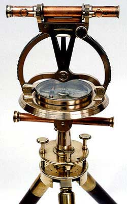
In the 18th and 19th century, instruments became more sophisticated to assist in the determination of elevations and more accurate angle measurements. The concept of triangulation flourished during this period and significant mapping was made for most of the civilized world. The early 1800s saw the westward push of expansion in the United States and Thomas Jefferson, U.S. president and former surveyor, led the charge to map the existing states and divide the west into sectional land for sale to settlers.
Besides the establishment of the Public Land Survey System, surveyors also provided topographic information for map of all sizes for future development planning. The late 1800s brought a large amount of topographic mapping information to paper through efforts by the U.S. Geological Society to map the entire United States. This information has been called the first land database; although crude in overall nature compared to today’s standards, it contained an enormous amount of topographic information.
These surveys continued well into the early 20th century until a revolutionary invention coupled with a current technology merged: the use of a mounted camera taking aerial photographs from an airplane. Geographers and photogrammetrists were able to use surveying data to assist with scaling orthometric photographs to create aerial images of thousands of acres of land. These aerial photos became the base layer for determining topographic features and contouring, covering much more land than ever before. Additional innovations included advancements in stereo plotting and photogrammetric techniques to further create high sophisticated topographic maps for the era. This type of mapping was the gold standard for decades depicting existing condition and topographic features for most of the world until the early 1970s and the computerized data revolution.
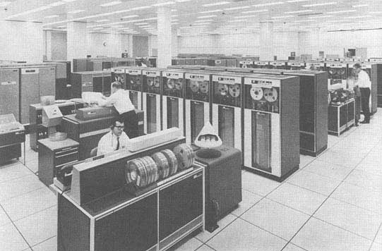
Computers take over the world (literally)
1960s mainframe computer (Photo: NASA)
While mainframe computers became more universally used in the 1960s, their use was contained to governmental agencies and large corporations. As the physical size of the computer reduced, the computing capacity increased, programming became easier to complete, and more applications were created to perform a variety of tasks. One of the biggest advancements for the era was electronic storage and analyzation of data through programming. Relational databases became a hot ticket for large datasets; geographic data was the perfect fit for this type of application. Modern mapping was on its way forward at warp speed.
Topographic mapping was not lost in this shuffle. The survey itself is based upon data points located on the face of the earth so each point is just another chunk of information within the database. Programming continued to advance and soon methods previous completed by manual methods over long periods of time were completed in a fraction of previous efforts without fail.
This effort was also joined with advancements in graphical technology to display this data on a computer video screen instead of lines of green text and numbers. Vector-based graphics, together with enormous point databases, helped create large topographical and geographical maps for many uses. During the same time the US put a man on the moon, mapping and platting of topographic information was also out of this world.
The turn of the century brings big changes
For the next decade, there were small advances in technology for topographic surveys and data points, but most were in presentation of data and increases in computing power. Pen plotters and smaller yet more powerful computers were becoming affordable to smaller companies, but it was still a large investment to get into the computerized data game for a surveyor. By the mid-1980s, electronic data collection with a total station was becoming the norm, but only meant collecting more points in a more efficient timeframe. The computing component did get faster but is still producing the same information of static data points.
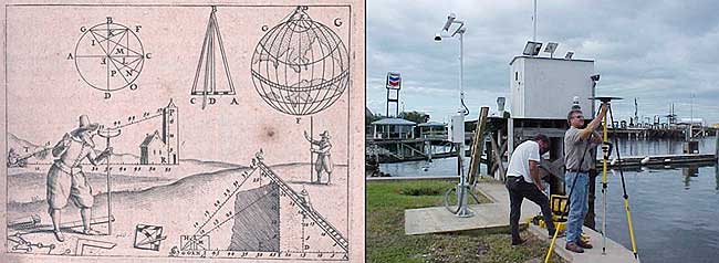
Ancient techniques and new technologies (Image: ngs.noaa.gov)
The mid-1980s also brought us a shiny new object: GPS technology. By the end of the 1990s, we were able to get out of our vehicle, start the receiver and collect geolocated points in minutes rather than hours. The big takeaway from this advancement is the geolocation component of the data point. Now everything can be related to one big dataset of topographical points. By creating a database with all our project data collected in the same georeferenced datums (horizontal & vertical), we can create digital models that replicate existing conditions.
We can also add another big advancement in data collection: remote sensing technology. From laser and lidar scanners, photogrammetry, SLAM technology and ground penetrating radar, the innovations to collect data at locations we can “see” through sensing are now a reality. Another significant improvement with this technology is the amount of data points remote sensing can collect, both in timing and spacing. We are now talking small scanning projects that consist of billions of points within the site point cloud. We are fortunate that our computing power and storage capabilities has increased exponentially along with the remote sensing. (Remember doing a “regen” on your CAD file and having time to get a cup of coffee?)
Lots of data — now what?
Data is powerful, especially when it is harnessed in a robust system that can analyze and model for future use. Yes, this condition also applies to the surveying world, even though you may not be thinking about it now. We can use this data to create a virtual world that mimics the one we live in; the difference is that we exist in ours yet model and manipulate the digital version in our computer system. The technology is now available, and we can make a replica of our current world; however, why would we want to do that? There are lots of reasons to use technology and data to make sophisticated topographic maps (because that is what they are) for recording the world around us.
One of the big differences now is that we have much more information about the data points we collect within our topographic maps. Sure, many surveyors will say that their data has not changed or evolved during their careers, but they would be wrong. Unless they are still manually writing it all down for hand plotting… (Hello! The 1960s called, and they want their field book back!) Every electronically collected point has attributes associated with the data.
These attributes, while they may be simple, contain important information about the datapoint it represents. Horizontal location? Check. Vertical elevation? Check. Assigned point number? Probably. Field code? Most likely. But it also has one other important component: time. We now know exactly when that point was collected. Why is that important?
Because, like a lot of instances, things change. Something collected today might not be there tomorrow. Time is just as important as the physical location and the type of point it represents.
Gather these points together, throw them in one big model and you have yourself a graphical database that can be analyzed, reviewed, and used for planning and design. It may be hard to visualize with just simple survey data using GNSS and/or a total station, but couple it with a scanner or photogrammetry, you have a powerful hunk of data for which to work.
Why is this workflow and modeling procedure important enough to dedicate an entire column about surveying and GNSS to? Because it used to be far in the future, but the need and availability to use it is now here in front of us. Surveying and GNSS are an important part of this effort to create three dimensional models. By using survey-grade data in conjunction with point clouds collected from remote sensing equipment, we can replicate the world around us in real time.
Yes, Virginia, there is a name for the modeling process…
Photo: iStock.com/alexsl
The name for the proposed modeling of this dataset is a digital twin. It represents a digital representation of a physical object or system. NASA famously used the concept for their space program to simulate situations and procedures of many different types of events. The concept has grown with the technology to graphically create almost anything through digitalization and computer modeling. Once the model is created, both actual and proposed data points can be included to represent the existing and future opportunities.
The idea of a digital twin is not new; technology, however, has pumped more life into its existence by leaps and bounds with computing power and data storage capability. I remember, early in my career, going into an architect’s office and seeing the scale model mockup of a new development or building. The streets in the model were perfect, there were no drainage issues, and it was a neat as a pin. Fast forward to the construction of the development and field changes were at every turn. A digital twin will allow for better planning, more thorough design and creating more cost-effective development. Many large cities have started compiling data and building their digital twin, including New York, Singapore, Boston, and Rotterdam. Engineering and planning for new and replacement facilities is very expensive yet analysts predict that having a digital twin to work will save a significant amount of money and time.
As a surveyor, what’s in it for me?
Software capability for the surveyor is already here. Companies, such as Hexagon, Trimble, Topcon and Esri to name a few, have been developing their software to accommodate this concept for many years. Still, lots of surveyors do not know about it. And we should. Many of us live in places where the infrastructure is well past its useful life period and should have been replaced long ago. By starting now with survey-grade data to be put into a real-time model, we can help our governmental agencies and their consultants to move towards a digital twin that will ultimately save money and possibly lives.
What this means for the surveyor is to further embrace technology and include remote sensing into your operation. If you have not started at least looking into UAVs and photogrammetry, you are already behind. Many aerial operations are making the next leap into mounting a LiDAR unit on their UAV to gain even more capability. Early adopters of laser scanners were probably second guessing their decision during the 2008 Depression but if they stayed with it, it will be a big payoff in the long run. The next leap will be into handheld scanning devices, including ones using SLAM (simultaneous localization and mapping) technology for locating interior and close-up improvements. These technologies will cost a significant amount of time and money to implement but municipalities, engineers and architects are going to be clamoring for the data any day now.
When it comes to surveying and mapping of existing facilities, the surveyor and technology makes a great team. Do not let point clouds, remote sensing, or terabytes of data scare you away from providing badly needed information to help assemble your local digital twin. In the long run, it will pay off for all who take on the challenge of building it.
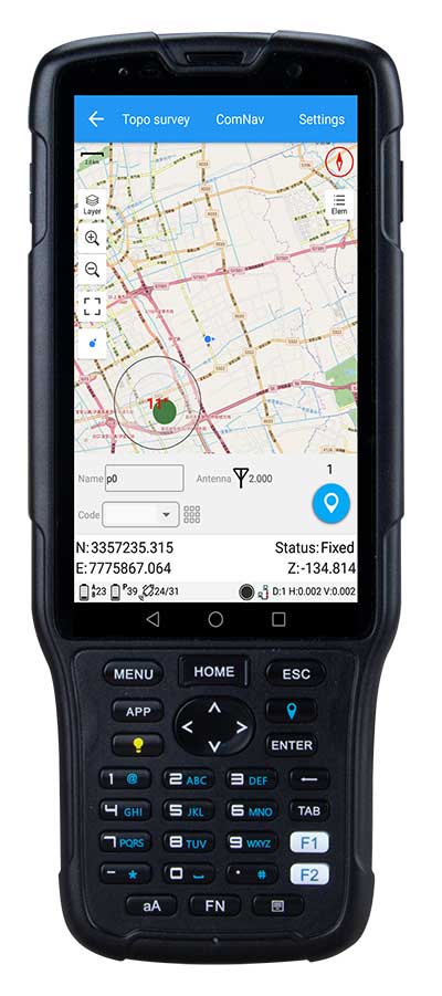
ComNav Technology has released the new-generation data collector R550.
With its new industrial-level design and new hardware platform, the R550 is designed to ensure efficiency and productivity in the field.
The IP67 dust-and-waterproof rating protects the R550 from most harsh environments. Equipping it with 7,000 mA Li-ion battery allows more than 14 hours of continuous operation, while fast-charging technology means it only takes four hours to fully charge the collector via the type-C interface port.
The 5-inch-wide sunlight-readable, high-resolution screen provides a smooth experience for any operation. The integrated autofocusing camera helps enhance job documentation by taking photos on site and sharing job information with colleagues.
Survey Master field software available on the R550 controller ensures efficient surveys in the field, including topographic surveys, stakeouts, coordinate geometry (COGO) and more.
Powered by the Android 8.1 operating system and designed with 4G RAM, 64GB ROM and 4G/BT/Wi-Fi on board, users can run other third-party apps based on their specific requirements.
The R550 data collector now is available through ComNav Technology authorized local distributors or ComNav Technology directly.