Tag: timing

  • When Am I?: The Importance of Time in Navigation

    A few months ago, many of you may remember that I wrote about an encounter with a rather well-known female journalist who, after listening to one of my GPS presentations, said something like this, “I came here today to learn more about GPS and so far all you have talked about is atomic reference systems…what the heck do those *&@# atomic clocks have to do with GPS…?”

    I mentioned at the time how incredulous I was at the question, but that I answered it with a straight face. Now, while professional courtesy prevents me from ever revealing the name of the female journalist, I will say that she evidently started an uncomfortable trend. Much of my correspondence lately has concerned the connections between time and position and/or navigation and why we are so concerned about time.

    I won’t bore my more sophisticated readers with GPS 101, or certainly not Time and Frequency Metrology 101, but I will tell you that I think we (this is not the royal “we” but includes all of us who work with and promote GPS on a daily basis) need to do a better job describing just how GPS works and more importantly how critical precise time and frequency is to position and navigation solutions, whether GPS is utilized or not. And I don’t have the time here to take up the argument concerning how important GPS is to our critical national infrastructure. Indeed, a topic and column for another time.

    I am sure my time and frequency metrology friends and colleagues at NIST (National Institute of Standards and Technology in Boulder, Colorado) and USNO (U.S. Naval Observatory — read as UTC — home of Coordinated Universal Time and the Master Clock) would probably go about this differently. They tend to approach these problems strictly from a metrology viewpoint. While there is nothing wrong with that perspective, I hope to give you a more hands-on operational view of time and how it relates to position and navigation.

    Smithsonian Institution and Time Exhibit

    An operational backup of a Transit 5-A satellite.
    An operational backup of a Transit 5-A satellite.

    Of course, I could take the easy way out and advise all my readers to visit the latest Smithsonian time exhibit entitled: Time and Navigation – The Untold Story of Getting From Here to There. The new exhibit opens in April.

    Here are a few quick Smithsonian facts, with commentary added, for those who want to visit and learn just what time has to do with GPS and navigation in general:

    What: The Relationship Between Time and Navigation

    When: Opens in April 2013.

    Where: The Smithsonian’s National Air and Space Museum, Independence Avenue at Sixth Street, S.W., Washington, D.C.

    Responsibility: “Time and Navigation — The Untold Story of Getting From Here to There” is being produced jointly by the Smithsonian’s National Air and Space Museum and the National Museum of American History. This is one of the few times, if not the first, that two museums have jointly produced a major exhibit of this importance.

    Sponsors: The exhibition is made possible through the generous contributions of Northrop Grumman; Exelis Inc.; Honeywell; National Geospatial-Intelligence Agency; U.S. Department of Transportation; Magellan; National Coordination Office for Space-Based Positioning, Navigation and Timing; Rockwell Collins; and ION the Institute of Navigation. Note: The sponsors are listed in order of the amount they gave to present the exhibition, but it should be noted that ION was among the first contributors, making the museums’ decision to go ahead with the exhibit a more comfortable one. More on that and why it is significant later.

    The USS Alabama.
    The USS Alabama.

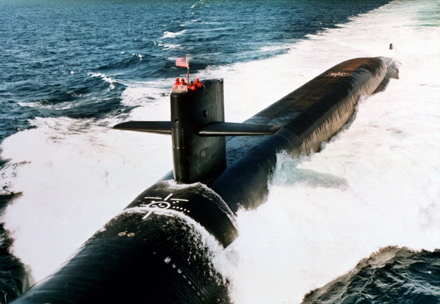
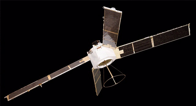
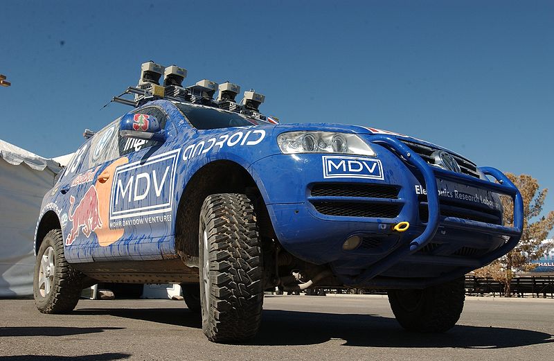
    Artifacts: (Don’t you just love the word artifact? Indeed, someone once told me, and not unkindly, that I resemble that word.) The time exhibition features 144 artifacts, drawn primarily from the collections of the participating museums. Highlights of the exhibition include a representation of a 19th-century ship from the U.S. Exploring Expedition; the first sea-going marine chronometer made in the United States; the submarine navigation system for the USS Alabama; a TRANSIT navigation satellite (a major naval predecessor to GPS); Wiley Post’s airplane, the Winnie Mae; and Stanley, originally from the Stanford University Racing Team and written about many times by yours truly in GPS World. Stanley is a robotic vehicle that can drive itself. Stanley is a 2005 Volkswagen Touareg, which has been considerably modified to navigate without remote control and without a human driver onboard. Stanley handily won the 2005 DARPA Grand Challenge (Defense Advanced Research Projects Agency), a robotic vehicle race. Stanley successfully navigated 212 kilometers (132 miles) across desert terrain and has had his (here we go, anthropomorphizing automobiles) own robotic exhibit at the Smithsonian since 2009.

    An official DARPA photograph of Stanley at the 2005 DARPA Grand Challenge. Stanley, created by the Stanford University Racing Team, won the race.
    An official DARPA photograph of Stanley at the 2005 DARPA Grand Challenge. Stanley, created by the Stanford University Racing Team, won the race.

    Organization: The current time exhibition is organized into five sections: Navigation for Everyone; Navigating at Sea; Navigating in the Air; Navigating in Space; and Inventing Satellite Navigation.

    Theme: If you want to know where you are, you need an accurate clock. In other words, you need to know when you are. About 250 years ago, sailors first used accurate clocks, later known as chronometers, to navigate the oceans. Today, we locate ourselves on the globe with synchronized atomic clocks in orbiting satellites (GPS is the primary method today). Among the many challenges facing navigation from then to now, one stands out: keeping accurate time.

    For centuries, nations have invested enormous resources to determine time and place for geopolitical reasons, and their research has changed people’s view of the world. Advanced technology that was once available only to the military has become commonplace and downloadable to cell phones, iPADS and computers. Instead of unfolding a map or stopping at a gas station to ask for directions, drivers can now consult their car’s GPS (Global Positioning) system. The new gallery examines the cultural and technological history of precise timekeeping and navigation at sea, in the air, and in space and the impact of satellite navigation on our everyday lives. Which of course are also the missions of the Institute of Navigation and GPS World magazine.

    When Am I?

    Many of you have heard the old saw about those who don’t know history being doomed to repeat it, and if you don’t know where you have been, how can you know where you are? There are probably numerous maxims that fit the bill when it comes to the history of time and navigation, and the Smithsonian Exhibit certainly does a great job of hitting all the high points, but beyond that, they will take you into about as much detail as you can stand. If possible, plan on attending the exhibit several times and delving into each of the five major themes. But if you can’t visit Washington, D.C., and the Smithsonian exhibit, then visit virtually on their excellent website.

    For our purposes, suffice it to say that you can’t really know where you are unless you know when you are. That requires a clock, the more precise the better, and consequently the more accurate your position.

    History Lesson

    More than 200 years ago, sailors sailing between Europe and the New World knew where they were only in relationship to their latitude, but had no idea other than dead reckoning of their longitude.

    Enter Boston clockmaker William Cranch Bond who, although he was not the first, constructed a specialized timepiece, which later became known as the Bond Chronometer, which sailors used to determine longitude at sea. But still there were problems. Sailors used a maritime sextant and chronometer to determine position, but both devices depended on the other. On cloudy or foggy days, either the horizon or the sun and stars or both were unavailable, and positioning/navigation was relegated to, in all seriousness, dead reckoning with a dubious magnetic compass, a rock and a rope. The problem being, of course, that dead reckoning made many mariners resemble the first word in that very unfortunate navigational phrase.

    Time and Air Navigation

    Fast forward almost a century (1903), and aeroplanes are now on the scene along with all the problems attendant in navigating a machine easily traveling ten times faster than most ships. But of course the U.S. Navy rationalized that if a watch and a sextant were good enough for navigating maritime ships, then they were good enough for ships of the air — even if the horizon was often obscured or moved around a great deal, or turbulence made balancing a sextant difficult.

    The result was most aviators gave up on the sextant, especially solo aviators, and just used a watch and, you guessed it, dead reckoning, which is exactly what happened to many aviators in 1927 who attempted to win the Raymond Orteig $25,000 prize for being the first solo aviator to cross the Atlantic nonstop from the East Coast of the U.S. — in fact, it had to be New York to Paris, France. For you trivia buffs, it had to be New York to Paris because the person offering the prize, Monsieur Raymond Ortieg, was an emigrant from France who did well for himself and went from a penniless restaurant busboy to owning two of the most prestigious hotels in New York City at the time. Hence the connection between New York and Paris. But I digress.
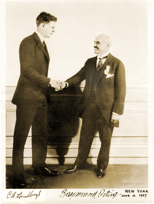
    Charles Lindbergh (left) and Raymond Orteig.
    Charles Lindbergh (left) and Raymond Orteig.

    Enter Lindbergh

    As most of you are aware, then captain, later colonel, Charles Lindbergh took up that dare and won the Orteig-prize on the 21 of May, 1927, when he landed in Paris after a grueling 33½-hour solo flight across the Atlantic. When Lindbergh hit land after being “feet wet” for more than 30 hours and 3500+ miles, he was less than three miles from his intended European entry point, a feat that would be hard to duplicate today without GPS, as even with an unaided inertial system the drift can sometimes be as high as one kilometer per hour.

    One part I always find amusing about the Lindbergh transatlantic saga is that after flying with “dead reckoning” as his only means of navigation for 30 hours across the Atlantic, he followed the Seine river all the way to Paris, so he essentially converted from VFR (Visual Flight Rules) to the IFR or “I fly rivers” navigation method for the last part of his journey.

    Meteorologists and the sealed barometric equipment Lindbergh carried on board — to prove he never landed enroute or that it was indeed a non-stop flight — would not only verify that fact but also verify that he navigated the Atlantic in what we might call today The Perfect Calm. Indeed, Lucky Lindy picked the perfect 48-hour period for his flight. For those of you who read the book, saw the movie, or were there, will remember that in New York the weather during the night preceding his historic takeoff from the dirt-churned-into-mud runway at Roosevelt Field, Long Island, New York, was less than cooperative. There was a major thunderstorm with lots of lightning and several inches of rain; consequently, many counseled Captain Lindbergh to postpone his flight. But he would have none of it and the rest is history.

    The most interesting part of the story, however, is that the entire flight was accomplished with “dead reckoning,” a compass and a watch, the very same tools that Captain Lindbergh used during his tenure as a U.S. Mail pilot. So, in fact, Lucky Lindy actually knew very little about navigating an airplane or avigation, as many called it at the time. Indeed, according to Roger Connor from the National Air and Space Museum and his wonderful article in this month’s Smithsonian Air & Space magazine, Even Lindbergh Got Lost, Captain Lindbergh did not learn to properly navigate with a sextant, chronometer and star charts until more than a year after his famous flight to Paris.

    I won’t spoil the story for you, but he learned to navigate as did his famous wife, Ann Morrow Lindbergh, from then Lieutenant Commander Philip V.H. Weems of the U.S. Navy. LCDR Weems set up the nation’s first independent navigation school, and went on to instruct such notables as General Curtis LeMay, the Commander of Strategic Air Command (SAC), who went on to serve as the Chief of Staff of the USAF. Most people are not aware, but General LeMay was dual-qualified as a pilot and a navigator in the USAF. As the Commander in Chief of SAC or CINCSAC, he mandated that all SAC flight crews be able to navigate from Point A to Point B using only passive means that were always available and did not involve transmitting a signal outside the aircraft. In other words, celestial navigation, using a sextant, chronometer, special plotter and star charts, much as was taught by LCDR Weems.

    I was one of the lucky SAC flight crew members who learned to navigate with those basic instruments. And checking my logbooks, I find that I made just short of 200 flights (99 round-trips) across the big pond, the Pacific that is, using those basic instruments. I mentioned this to a group of USAF aircrews recently during a speech, and when I asked how many of them could accomplish that feat if required to do so today, I was informed that sextants are no longer carried on USAF aircraft and most do not even have sextant ports. In other words, it is a lost art among flight crews today, and it is a shame, but it is also a topic for another time.

    The important fact concerning navigation and time is that time — indeed, precise time — is and always has been critical to accurate navigation, especially aircraft navigation, no matter whether you are flying from New York to Paris, Texas, or New York to Paris, France. And GPS Atomic Reference Systems (Atomic Clocks) on orbit today, which deliver time accurate to millionths of a second, are even more critical since they are the heart of the system. So I would say to my journalist enquirer, GPS and atomic clocks are one and the same. You can’t navigate accurately without precise time.

    Weems Legacy

    Now, to bring this full circle, I first heard about the proposed Smithsonian Time Exhibit about two years ago from a friend and professional colleague, James Doherty, Captain, USCG retired. Jim, who once served as the Commander of the United States Coast Guard Navigation Center, is a past President of ION (Institute of Navigation), one of the few U.S. members of the Royal Institute of Navigation (RIN) in London, England, and now serves as the Chairman of the newly created Military Division at ION. And for full disclosure purposes, I must say that I have been a proud member of ION for more than 30 years.

    Jim, who was serving on a Smithsonian panel as a subject-matter expert on navigation, told me that the Smithsonian had the idea for the time exhibit, but was looking for support, and the first organization to pledge support was indeed ION. The Institute of Navigation certainly does not have the deep pockets of Northrop and Exelis or the other major sponsors, but they are very serious about navigation and they are always looking for ways to promote their vision. This was the perfect opportunity.

    And just in case you were wondering, the legacy that Captain, U.S. Navy, V.H. Weems left the world is a method of celestial navigation that persisted as the primary means, especially in the U.S. military and military forces around the world, for more than 60 years and is still the only reliable means of navigation available to us when everything else goes away. For with the Weems Method, as long as you have a sextant and an accurate clock, you can navigate anywhere.

    Oh, and one other legacy: Captain V.H. Weems was the founder of the Institute of Navigation, which is the leading society devoted to the advancement of navigation in the world today. And for you trivia fans, the ION predates the RIN by two years.

    Sequestration and Cancellations

    Normally I would wrap it up here and say grab your sextant and happy navigating, but just as I wrap this up I have been told by informed sources at SMC and AFCEA that the GPS Partnership Council scheduled for May this year has been postponed. Sources at ION tell me that ION/JNC in Orlando has been cancelled for this year due to the restrictions on travel for U.S. government and military officials. In other words, more victims of sequestration and a Congress that can’t make the decisions we elect and pay them to make.

    At ION they have always had the mantra, do it right or don’t bother doing it at all, and this year the travel restrictions are just too great. Certainly Jim Doherty and I were in the process of setting up another great Warrior Panel for the classified day, but that will have to wait for another time. However, I am assured by ION Executive Director Lisa Beaty that the ION GNSS meeting from September 16-20 at the Nashville Convention Center is definitely a go, so I look forward to seeing everyone there. Stop by the GPS World booth and say hello. Plus, I hope to see many of you at the 29th Annual National Space Symposium in Colorado Springs from April 8-11, 2013.

    Until then, Happy Navigating – blow the dust off your sextant and give it a shot.

  • ESA’s Navigation Lab Helps Set Global Time

    The European Space Agency (ESA) is helping to set the world’s time. Ultra-accurate atomic clocks of ESA’s Navigation Laboratory, which will be used to assess performance of the Galileo satnav system, have joined the global effort setting Coordinated Universal Time down to a billionth of a second.

    The replacement for Greenwich Mean Time, Coordinated Universal Time (UTC) is the timing used for Internet, banking, and aviation standards, and other international timescales, maintained by the Paris-based Bureau International de Poids et Mesures (BIPM).

    Participating measurement institutes and observatories around the globe use collections of atomic clocks to estimate a current value for UTC. These clock data are fed through to the BIPM to be carefully weighted and averaged to derive a combined global value. The complexity of this effort is such that it takes around six weeks to arrive at a definitive final figure, ESA said.

    Atomic clocks at ESTEC's Navigation Laboratory. Once Galileo services start, ESA’s Navigation Lab will play an important role independently validating Galileo timing performance. Its atomic clocks, offering precise timings for ESA  missions and experiments, are also contributing to the global setting of Coordinated Universal Time (UTC), the replacement for GMT.
    Atomic clocks at ESTEC’s Navigation Laboratory. Once Galileo services start, ESA’s Navigation Lab will play an important role independently validating Galileo timing performance. Its atomic clocks, offering precise timings for ESA missions and experiments, are also contributing to the global setting of Coordinated Universal Time (UTC), the replacement for GMT.

    ESTEC Director Franco Ongaro has signed an agreement with BIPM to mark the international recognition of the ESA timescale and the addition of ESA’s atomic clock data to the UTC calculations. “This is an independent timing capability that ESA’s Navigation Laboratory — based in ESTEC in the Netherlands — built up to support validation of Galileo timing performances, and before it the experimental Galileo GIOVE satellites,” explained Pierre Waller of ESA’s RF Payload Systems division.

    “But it makes sense to apply it more widely, and this BIPM recognition reflects the quality of our data. Our UTC estimate — formally known as UTC (ESTEC) — is also available for projects within ESA: there are many space applications beyond just navigation, such as precision technical experiments or synchronization of telecommunications and deep-space ground stations.

    “Incidentally, it is important to note that our contribution to UTC does not replace the existing input from the Netherlands’ own national timing metrology institute, Van Swinden Laboratories (VSL) in Delft. Instead we are adding to it, for enhanced global accuracy overall.”

    Galileo, like all other satellite navigation systems, is based on the highly precise measurement of time. A receiver on the ground pinpoints its position by calculating how long signals from satellites in orbit take to reach it.

    Matching the receiver and satellite clocks then multiplying the time taken by the speed of light gives the range between the user and the satellite. This allows the receiver to fix its longitude, latitude and time when in contact with four or more satellites. Atomic clocks on each satellite keep time to a matter of nanoseconds — billionths of a second — synchronized by a worldwide ground network.

  • Symmetricom Enhances SSU 2000 Platform with GLONASS

    Symmetricom, Inc. today announced two new capabilities for its SSU 2000 Synchronization Supply Unit: a GLONASS timing reference that uses signals from the satellite navigation system operated by the Russian Aerospace Defense Forces, and Synchronous Ethernet (SyncE), an ITU-T synchronization standard that delivers frequency synchronization over the Ethernet physical layer.

    This enhanced version of the SSU 2000 will be the first in a series of forthcoming Symmetricom products that include GLONASS capabilities.

    Available as an integrated card for the Symmetricom SSU 2000, the GLONASS referencing feature will allow customers to support both GPS and GLONASS simultaneously, providing added protection should signals from one navigation system become unavailable. GPS has long served as the primary reference signal for timing and synchronization in telecommunications and other networks. Operators in some regions prefer to use the GLONASS system, either as the primary time reference or in conjunction with GPS signals. Symmetricom has enhanced the SSU 2000 satellite receiver functionality to meet this demand.

    “GLONASS signals have become an important primary reference for timing and synchronization systems,” said Laura Finkelstein, vice president of product management for Symmetricom. “The SSU 2000 is well-established as the synchronization platform for communication service providers globally. The integrated capability to simultaneously support both GPS and GLONASS provides our customers another way to improve the reliability of their network.”

    Timing and synchronization are a focal point technology in Ethernet and mobile carrier networks today. Synchronous Ethernet allows frequency signals to transfer at the physical layer over Ethernet, helping improve network reliability by offering synchronization services to Carrier Ethernet networks. Using SyncE to complement IEEE 1588 Precision Time Protocol (PTP) can enhance PTP services being delivered to mobile base stations deployed in radio access networks. The new SSU 2000 capability puts SyncE and PTP on the same output port, thus providing an ideal synchronization solution for the evolution of mobile networks as they extend coverage and increase capacity.

    Designed in a NEBS-compliant package, the SSU 2000 integrates intelligent functional modules into a flexible, fully redundant system. This enables telecom network operators to seamlessly satisfy current and future requirements for generating and distributing superior synchronization signals for advanced network services.

    The SSU 2000 has been deployed in more than 125 countries as a timing and synchronization distribution system for communications service providers.

  • Symmetricom Delivers Precise Time to Next-Generation Smart Grid

    Symmetricom, Inc., a precision time and frequency technologies company, today announced a new timing solution that meets the stringent microsecond accuracy requirements of Smart Grid substations. Specifically designed for substation operations, such as wide area measurement systems, traveling wave fault locators and sampled values, the Symmetricom SyncServer SGC-1500 Smart Grid Clock offers power utility companies accurate, secure and reliable timing and synchronization for their mission-critical operations. This means companies like Pacific Gas & Electric (PG&E) will be able to mitigate outages with real-time monitoring for grid stress, frequency instability, voltage instability and reliability margins.

    The Smart Grid has brought about power technology advancements that fundamentally change substation operations. Power equipment and their data networks are shifting from simple, reactive control and reporting to proactive, real-time management and operations control, making advanced synchronization and timing more critical than ever, according to Symmetricom. The SGC-1500 Smart Grid Clock is designed to address this need, enabling power equipment to operate more efficiently and closer to its operational limits. For example, one microsecond accuracy is required by the phasor measurement unit (PMU) for real-time network situational awareness and overall operational efficiency. Without accurate time stamps, PMU data has limited value. For power utility companies, that translates into enhanced network utilization rates as well as smarter management and mixing of renewable and traditional power sources.

    “Power and utility companies are increasingly looking to source the latest technology innovations in order to modernize their infrastructure,” said Greg Neichin, executive vice president, Cleantech Group. “Over the past three years, we have tracked more than $700 million in venture investment committed to companies developing smart grid products. These are all data-intensive applications that will rely heavily on precise timing and synchronization, as well as more advanced analytics to process these vast streams of new information.”

    “The Smart Grid architecture and related standards require a new approach to timing distribution across the overall network,” said Manish Gupta, vice president of marketing and business development for Symmetricom. “Symmetricom brings extensive experience in delivering precise time to the communications, government, and enterprise markets. Serving the power utility telecom network over the past 10 years, Symmetricom is ideally positioned to meet the emerging timing requirements of the Smart Grid.”

    The SyncServer SGC-1500 meets key requirements of Smart Grid substations, including:

    • Microsecond accuracy and resiliency — referencing GPS satellite signals, the Symmetricom Smart Grid Clock distributes timing with microsecond accuracy over the local area network (LAN) using the IEEE 1588 v2 Precision Time Protocol (PTP) Power Profile or IRIG-B time code.
    • IEC 61850 — the International Electrotechnical Commission’s (IEC) standards for the design of electrical substation automation, which requires microsecond timing to identify and mitigate a potential fault condition in real time. This standard also identifies important electrical hardening requirements for substation environments.
    • NERC CIP ― the North American Electric Reliability Corporation (NERC) reliability and security standards for Critical Infrastructure Protection (CIP), which calls for high strength security protocols.

    The SyncServer SGC-1500 comes with additional industry leading capabilities such as a built-in IEEE 1588 v2 Telecom Profile input option. This enables the Smart Grid Clock to derive time from the communications wide area network (WAN), thus eliminating the need to have GPS at every substation and PMU. The Rubidium atomic clock option offers holdover capability in the event of GPS disruption. These options result in a highly cost effective and resilient solution for power utilities.

  • Leadership Awards 2012: At the Frontiers of Time

    Robert Lutwak, Symmetricom, winner in the Product category.
    Robert Lutwak, Symmetricom, winner in the Product category.
    New Advances in Receiver Performance and Reliability

    Editor’s Note: This article reproduces the acceptance speeches given by the winners of GPS World’s 2012 Leadership Awards, at the Leadership Dinner in Nashville in September. The Leadership Dinner was sponsored by Lockheed Martin and Deimos Space.


    Remarks by Robert Lutwak, Symmetricom; Chief Scientist, winner in the Products category. His expertise is practical advances to overcome the intrinsic physical barriers to affordable chip-scale atomic clocks, enabling precision time and time transfer in mobile GNSS and communications systems.

    Thank you to the awards committee and especially to the individual who nominated me.

    I would be remiss if anyone left here with the impression that the development of the chip-scale atomic clock was in any way a solo effort. On the contrary, while I have had the privilege of being the front man, the success of this program can be attributed entirely to the fantastic collaboration between three highly disparate groups, from very different industries and cultures: our Research Group at Symmetricom’s Technology Realization Center, in Beverly, Massachusetts; the MEMS group at the Charles Stark Draper Laboratory, led by Mark Mescher and Matt Varghese; and the optoelectronics group at Sandia National Laboratories, led by Darwin Serkland.  If any of these groups and people had been anything less than extraordinary, both technically and personally,I would not be standing here this evening.

    With this introduction I can say, with little loss of humility, that the chip-scale atomic clock (CSAC) is a really cool device. Depending on where you’re coming from, it’s either 100 times lower size, weight, and power (SWAP)  than traditional atomic clocks or it’s 100 times more accurate than quartz oscillators with comparable SWAP. Regardless of your perspective, it clearly represents a disruptive technology and a paradigm shift for portable battery-powered navigation, communication, and timing applications. For comparison, the CSAC can run for a day on a full cellphone battery charge, whereas the next lowest power clock of comparable performance will run down a car battery in an hour. The CSAC is not an evolutionary improvement in SWAP, it is revolutionary in that it enables previously untenable system architectures, mission scenarios, and network topologies.

    Since Symmetricom introduced the first commercial CSAC, roughly two years ago, the market response has been overwhelming. Despite having done our due diligence to predict the market demand and despite having nearly doubled our manufacturing output every quarter, our shipment backlog remains strong, and I am frequently surprised by innovative customer applications that we had not envisioned at the product launch. We have to date shipped many thousands of CSACs to more than a hundred different customers, representing vastly different markets and applications. While many of the novel applications are still in the early stages of prototype development and evaluation, it is clear that CSACs will be ubiquitous across diverse applications within the decade.

    I am fortunate, in my position, to interact directly with the technical integrators of the CSAC and learn the details of many of the applications. My general impression is that the timing and frequency stability performance of the CSAC is adequate for most of the emerging applications. The most common requests that I hear from customers are for reduced cost, power consumption, and size, in that order. It is not surprising that size is at the bottom of the list. In most applications, the batteries are still larger and heavier than the CSAC, so small improvements in power consumption are generally more valuable to reducing system SWAP than size reduction of the CSAC itself.

    As in any new technology, the cost will come down naturally with increased volume and improved manufacturing efficiencies, both at Symmetricom and at our vendors. While it is unlikely that you will get a CSAC in your next free cellphone, I do expect that the cost will progressively decrease over the next several years, and the technology will become cost-viable to an exponentially increasing spectrum of applications. Similarly, we continue to evolve our electronics and algorithms for improved power consumption, aided by external advancements in microwave and microprocessor electronics driven by the smart-phone industry. It is my expectation that a factor of 2X improvement in power consumption is likely within the next three to five years.

    To date, most of the commercial products that have emerged, based on CSAC technology, have been in the timing and frequency calibration space. It is not surprising to me that the time and frequency community was the first to adopt and exploit the technology, as many of them have been closely monitoring the development program and had the internal expertise and experience to rapidly exploit it.

    I admit, though, that I am a bit disappointed to see that there are no papers with “CSAC” in their titles at the 2012 ION-GNSS, but I am confident that this will change in the years to come. Adoption of CSAC by the navigation community has lagged behind the timing community in large part, I believe, because the technology has caught the community somewhat off-guard, and the benefits of the CSAC to INS and GNSS are just now beginning to be realized.

    The most obvious and straight-forward application of CSAC to GNSS is rapid P(Y) acquisition; we have demonstrated 15-second time-to-subsequent-fix (TTSF) after two hours of GPS denial. This was a fairly simple demonstration that consisted of jamming time into an unmodified GPS receiver, but I believe that this is just the tip of the iceberg. With access to the core navigation algorithms within the receiver, precise knowledge of time could improve the receiver performance and reliability on other levels, including (at least):
    ◾    Improved uncertainty of the navigation solution
    ◾    Navigation with less than four (or less than three) satellites
    ◾    Anti-spoof and anti-jam detection
    ◾    Seamless co-integration of GNSS and INS systems

    Another navigation area that I believe is ripe to benefit from CSAC technology is in self-assembling navigation systems, such as a local ad hoc GNSS-like network which self-assembles from handheld timing beacons/receivers. Such a system would have value for safety-of-life applications in GPS-denied environments, such as indoor firefighting and mine safety.

    Thank you again for the recognition and opportunity of this award.

  • Symmetricom Expands Test Set Portfolio with High-Performance Test Probe

    Symmetricom, Inc., has launched a high-performance, low-cost measurement solution, the Symmetricom 3120A Phase Noise Test Probe, which can be used to test reference clocks. The latest addition to Symmetricom’s state-of-the-art timing test set portfolio, the 3120A Test Probe comes in a convenient small form factor and measures phase noise and Allan deviation as part of the base hardware kit. Additional software options are available to measure AM noise floor and signal statistics such as HDEV, TDEV, MDEV and jitter, and for use as a frequency counter and for mask testing.

    Unlike traditional solutions that are desktop-bound due to size and weight, Symmetricom’s 3120A Test Probe is small enough to be carried around from location to location, and inexpensive enough to have at each bench. Whether used on a busy manufacturing floor, in a tight server closet or in R&D labs, the 3120A helps characterize reference clocks, used in high-performance applications, to achieve the highest accuracy without requiring calibration.

    The 3120A Test Probe comes with intuitive software to take measurements and conduct analysis, the company said. The 3120A Phase Noise Test Software displays results in seconds without the need for external data processing.

    “The Symmetricom 3120A is an excellent low-cost phase noise test probe that customers can use with their existing PC equipment to achieve state-of-the-art measurements,” said Sam Stein, chief scientist for Symmetricom. “It is an ideal extension to Symmetricom’s line of phase noise products.”

    Symmetricom will introduce the 3120A Test Probe at the Precise Time and Time Interval (PTTI) Systems and Applications Meeting, which takes place on November 26 – 29 in Reston, Virginia. Symmetricom will be at booth #6 conducting demonstrations and providing information about the 3120A Test Probe, in addition to Symmetricom’s other timing and synchronization products.

  • National Instruments Launches GPS Time-Stamping and Synchronization Module


    National Instruments has announced the NI 9467 GPS synchronization module, which accurately synchronizes a large-scale CompactRIO system with features such as data time-stamping and system clock setting.

    The NI 9467 is one of six new C Series modules designed for NI CompactRIO embedded control systems and NI CompactDAQ modular data acquisition systems. By expanding the C Series platform, NI provides engineers and scientists with new and improved options for a wide variety of embedded control, monitoring and data acquisition applications. Channel counts on the individual modules range from three to 32 channels to accommodate a wide range of system requirements, and the majority of C Series modules work in both the NI CompactDAQ and CompactRIO measurement platforms with no modification.

    “We rely on National Instruments hardware and software to provide the rugged, distributed control we need for our wind turbine system,” said Jonathan C. Berg, mechanical engineer at Sandia National Laboratories. “The site-wide architecture uses NI VeriStand and the NI 9467 GPS module to choreograph all of the data acquisition and control operations.”

    “This is the largest C Series module release in several years, reflecting our ongoing commitment to expanding the NI LabVIEW RIO architecture,” said Jamie Smith, director of industrial embedded marketing at National Instruments. “At NI, we constantly innovate and build upon our systems to help engineers simplify development.”

    Features of the NI 9467 include:

    • Pulse per second (PPS) accuracy of ±100 ns, >99 percent typical
    • SMA female antenna connector type (antenna sold separately)
    • +5 VDC (up to 30 mA) for active GPS antenna
    • Returns stationary global position after self-survey (module does not work for mobile applications)
    • NI CompactRIO support only
    • NI recommends using the NI 9467 with the NI FPGA Timekeeper.
  • Symmetricom Introduces Small Cells Category to SyncWorld Ecosystem Program

    Symmetricom, Inc., today launched a new small cells-focused category within its SyncWorld Ecosystem Program. Developed to support the integration with Symmetricom’s SCr/SCe NTP/ PTP and sGPS SoftClocks and interoperability between Symmetricom Grandmaster clocks and other small cells solutions, the category aims to facilitate validated deployments of timing and synchronization with various small cells products in 3G and 4G/LTE architectures. Current partners in the program include leading small cell players Alcatel-Lucent, Broadcom, Cavium, Contela, CS Corporation, Mindspeed, Node-H, Qualcomm Atheros, and Rakon.

    Small cells are a key component of 3G and 4G architectures as they add capacity to the mobile network and allow service providers the maximum leverage of scarce spectrum resources. Successful HetNet deployments require small cells to synchronize seamlessly with the macro base stations irrespective of backhaul type. Also, small cell design cycles need to be short to meet the fast evolving market needs. SyncWorld brings together all players in the ecosystem including semiconductors, oscillators, software, test equipment and system vendors to drive cost effective and shortened design cycles by enabling architectural harmony and interoperability.

    Analyst firm Infonetics forecasts the global small cell market to grow to $2.1 billion in 2016 as small cells have emerged as a key solution to deliver increased network capacity. Symmetricom has delivered a number of solutions with partners along with the introduction of the industry’s first small cell synchronization solution, SCr/SCe NTP/ PTP and sGPS SoftClocks for residential and enterprise small cells. The small cells segment within the SyncWorld Ecosystem Program will ensure that interoperability needs are met as service providers accelerate their deployment plans.

    “The small cells category represents leaders across the entire value chain,” said Manish Gupta, vice president of marketing and business development for Symmetricom. “Working together, SyncWorld small cell members will be able to give service providers a comprehensive, integrated and simplified solution that is interoperable and supports the specifications required to support 4G/LTE networks.”

    The SyncWorld Ecosystem Program enables vendors to cooperate with the goal of providing complete solutions that interoperate with the most recognized timing and synchronization solution provider in the industry. Vendors that produce silicon, small cell access point, software and oscillators are invited to apply for the program online.

    With solutions deployed globally in more than 150 networks, Symmetricom is committed to partnering with trusted end-to-end technology providers which deploy and maintain networks on behalf of operators.

  • Symmetricom Launches RoHS Compliant GPS Time Servers

    Symmetricom, Inc., has introduced new RoHS compliant versions of its existing SyncServer S200 and SyncServer S250 GPS Network Time Servers. Designed for large or expanding IT enterprises, the cost-effective SyncServer S200 and S250 with optional rubidium-based atomic clocks will reliably continue operational service for extended periods when primary time sources are impaired.

    Accurate network time-keeping is essential for modern data networks to support a number of key functions — including precision time stamping, scheduled data backups, network management and security. These functions all rely on networked clocks to stay synchronized with each other. By using enterprise owned servers, companies are better poised to ensure accurate, reliable and more simplified network timing and synchronization, Symmetricom said.

    The European Union’s Restriction of Hazardous Substances directive (or RoHS) assures environmental responsibility for the materials used in electrical and electronic equipment. The SyncServer S200 and S250 now offer network managers and engineers RoHS certified, entry-level time servers that still allow them to take advantage of rubidium-based clock technology. Unlike the more commonly deployed time servers that leverage temperature-compensated crystal oscillator (TCXO) and oven-controlled crystal oscillator (OCXO) technologies, the rubidium-based SyncServers provide superior holdover — technology that allows the network to continue to operate with accurate timing when the primary reference (usually GPS) is temporarily impaired due to events such as GPS jamming, antenna breakage, or solar interferences.

    Communications and information technology managers can now take control of their network timing and synchronization and be assured of very accurate timing in their network that will not degrade or disrupt services during long periods where holdover is necessary, Symmetricom said.

  • Going Up Against Time: The Power Grid’s Vulnerability to GPS Spoofing Attacks

    By Daniel P. Shepard, Todd E. Humphreys, and Aaron A. Fansler

    Spoofing tests against phasor measurement units demonstrate their vulnerability to attack. A generator trip in an automatic control scheme could be falsely activated by the GPS spoofing, possibly leading to cascading faults and a large-scale power blackout.


    As electric power grids continue to expand throughout the world and as transmission lines are pushed to their operating limits, the dynamic operation of the power system has become a serious concern and increasingly difficult to accurately model. More effective real-time system control is now seen as key to preventing wide-scale cascading outages like the 2003 Northeast Blackout.

    For years, electric power control centers have estimated the state of the power system (the positive sequence voltage magnitude and phase angle at each network node) from measurements of power flows. But for improved accuracy in the so-called power system state estimates, it will be necessary to feed existing estimators with a richer measurement ensemble or to measure the grid state directly.

    Alternating current (AC) quantities have been analyzed for over 100 years using a construct developed by Charles Proteus Steinmetz in 1893, known as a phasor. In power systems, the phasor construct has commonly been used for analyzing AC quantities, assuming a constant frequency. A relatively new synchronization technique which allows referencing measured current or voltage phasors to absolute time has been developed and is currently being implemented throughout the world. The measurements produced by this technique are known as synchronized phasor measurements or synchrophasors.

    Synchrophasors provide a real-time snapshot of current and voltage amplitudes and phases across a power system, and so can give a complete picture of the state of a power system at any instant in time.  This makes synchrophasors useful for control, measurement, and analysis of the power system.

    A device used to measure synchrophasors is called a phasor measurement unit (PMU). In a typical deployment, PMUs are integrated in protective relays and are sampled from widely dispersed locations in the power system network. They are synchronized with respect to the common time source of a GPS clock. PMUs basically measure AC voltage (or current) and absolute phase angles at selected locations in an electric transmission or distribution system.

    GPS Spoofing

    GPS spoofing is the act of producing a falsified version of the GPS signal with the goal of taking control of a GPS receiver’s position-velocity-time (PVT) solution. This is most effectively accomplished when the spoofer has knowledge of the GPS signal as seen by the target receiver so that the spoofer can produce a matched, falsified version of the signal. In the case of military signals, this type of attack is nearly impossible because the military signal is encrypted and therefore unpredictable. On the other hand, the civil GPS signal is publicly-known and readily predictable.

    In recent years, civil GPS spoofing is becoming recognized as a serious threat to many critical infrastructure applications which rely heavily on the publicly-known civil GPS signal. A number of promising methods are currently being developed to defend against civil GPS spoofing attacks, but it will still take a number of years before these technologies mature and are implemented on a wide scale. Currently, there is a complete absence of any off-the-shelf defense against a GPS spoofing attack.

    See “Generation, Transmission” sidebar at the end of this article for background on the following tests.

    The Tests. The minimum threshold for success was to show that a GPS spoofer could force a PMU to violate the IEEE C37.118 Standard “Synchrophasors for Power Systems,” which defines accuracy as a vectorial difference between the measured and expected value of the phasor for the measurement at a given instant of time, called the total vector error (TVE).  TVE blends three possible sources of error: magnitude, phase angle, and timing. An error in timing appears identical to an error in phase angle. Without timing and magnitude errors, a phase angle error of 0.573o corresponds to a 1 percent TVE, the maximum allowable by the IEEE C37.118 Standard. This phase angle error could be equivalently and indistinguishably caused by a timing error of 26.5 µs, which was chosen as the threshold for success in the spoofing tests.

    The Spoofer

    The civil GPS spoofer used for these tests is an advanced version of the spoofer reported in “Assessing the Spoofing Threat,” GPS World, January 2009. A block diagram of the spoofer is shown in Figure 1. It is the same spoofer used in the tests described in “Drone Hack” in this issue of the magazine, and a detailed description is given in that article.

    The spoofer can carry out a sophisticated spoofing attack in which no obvious clues remain to suggest that an attack is underway. The University of Texas spoofer and attack strategy have been tested against a wide variety of GPS receivers and has always been successful in commandeering the target receiver.

     Figure 1. Block diagram of the University of Texas spoofer used to attack the phasor unit.
    Figure 1. Block diagram of the University of Texas spoofer used to attack the phasor unit.
    Test Setup

    Figure 2 shows a schematic of the setup used for the open-air tests. The signals received at the roof were routed into the spoofer for use in producing the counterfeit signals and into the RF shielded tent for rebroadcasting. The counterfeit signals were also routed into the tent for broadcasting. In addition to the antennas broadcasting the authentic and counterfeit signals, a third antenna was setup inside the tent to receive the combination of authentic and spoofed signals. This setup is representative of an actual attack scenario where the malefactor does not have physical access to the victim receiver’s antenna input but rather broadcasts the spoofed signals over-the-air. For cable-only tests, the entire setup inside the tent was replaced with a signal combiner that summed the authentic and spoofed signals.

    Figure 2. Schematic of the test setup.
    Figure 2. Schematic of the test setup.

    The combined authentic and spoofed signals were fed to the victim GPS time reference receiver. The output timing signal from the victim receiver was used as the synchronization reference for one PMU, whereas a second PMU was given timing from a separate GPS time reference receiver that was tracking only authentic GPS signals. Since the PMUs were in the same room and measured the local voltage and carrier phasors, both PMUs would report roughly the same phasor measurements under normal circumstances. Thus, any significant differences in the phase angle measurements between the two PMUs could be attributed to the effects of spoofing.

    Test Results

    Both the cable-only and the over-the-air spoofing attacks were successful in leading the PMU phase measurements off from the truth. Figure 3 shows the measured phase angle difference between the reference PMU, which was fed the true GPS signal, and the spoofed PMU throughout one entire test. This value would normally be less than a few degrees in the absence of spoofing, since the two PMUs are co-located. After the initial ten minute capture-and-carry-off, which proceeds slowly to avoid detection, the spoofer accelerates its carry-off and the reference and spoofed phase angles quickly diverge.

    Figure 2. Schematic of the test setup.
    Figure 3. A plot of the phase angle difference between the reference and the spoofed PMUs. Normally the phase angle difference would be nearly zero in the absence of a spoofing attack. Point 1 marks the start of the test. Point 2 marks the point at which the spoofer has completely captured the victim receiver. Point 3 marks the point at which the IEEE C37.118 Standard has been broken. Point 4 marks the point at which the spoofer-induced velocity has reached its maximum value for the test. Point 5 marks the point at which the spoofed signal was removed.

    Figure 4 shows pictures of an oscilloscope and the Synchrowave screen at the start of the test. The oscilloscope shows two pulse-per-second (PPS) signals, with the upper yellow pulse coming from a reference clock being fed true GPS and the lower blue pulse coming from the spoofed timing receiver. Both PPS signals are initially aligned with each other. The Synchrowave screen displays the PMU phase angle data in real-time as phasors with the nominal 60 Hz operating frequency subtracted from the phase angle. The red and green phasors show the phase data from the reference and spoofed PMUs respectively. These phasors are within a few degrees of each other at the beginning of the test.

     Figure 4. Oscilloscope (left) and Synchrowave (right) screen at the start of the test, which is marked as point 1 in Figure 3.
    Figure 4. Oscilloscope (left) and Synchrowave (right) screen at the start of the test, which is marked as point 1 in Figure 3.

    Figure 5 shows pictures of the Oscilloscope and the Synchrowave screen at about 620 seconds into the test. At this point, the spoofer has moved the victim receiver 2 µs off in time and has completely captured the receiver.  The delicate initial capture-and-carry-off is performed at a slow rate to suppress any evidence of the spoofer’s presence. However, this process could be done quicker because the receiver was not looking for such evidence of foul play. At this stage of the test, there is not yet any significant difference between the two phasors on the Synchrowave screen, since the spoofed time offset remains relatively small. The oscilloscope, however, reveals that the PPS output from the victim receiver has moved by about 2 µs relative to the reference PPS. At this point, the spoofer begins to accelerate the victim receiver’s time solution at a distance-equivalent rate of 4 m/s2 until it reaches a final distance-equivalent velocity of 1000 m/s. Distance-equivalent velocity can be converted into the actual time rate of change of time by dividing by the speed of light.

     Figure 5. Oscilloscope and Synchrowave screen at about 620 seconds, point 2 in Figure 3.
    Figure 5. Oscilloscope and Synchrowave screen at about 620 seconds, point 2 in Figure 3.

    The acceleration segment of the attack must be tailored to the individual receiver’s ability to track the spoofer-induced dynamics. Otherwise, the spoofer risks losing control of the victim receiver’s tracking loops by moving too quickly for the receiver to track or by raising alarms. Alternatively, a malefactor could survey possible GPS time reference receivers that might be used and tailor the spoofing attack such that any of the receivers would track and believe the spoofed signals. This would place severe limits on the spoofer’s ability to manipulate timing, but would not make the attack impossible or implausible.

    Figure 6 shows the oscilloscope and Synchrowave screen at about 680 seconds into the test. At this point, the spoofer has broken the IEEE C37.118 Standard for PMUs, which requires accuracy in the measured phase angle of 0.573o. This demonstrates a significant vulnerability for PMU-based monitoring and control, since these applications leverage the accuracy supposedly guaranteed by the standard. There is yet no noticeable difference on the Synchrowave screen, but the oscilloscope clearly shows that the victim receiver has now been offset in time by about 20 µs.

     Figure 6. Oscilloscope and Synchrowave screen at about 680 seconds, point 3 in Figure. 3.
    Figure 6. Oscilloscope and Synchrowave screen at about 680 seconds, point 3 in Figure. 3.

    Figure 7 shows pictures of the oscilloscope and the Synchrowave screen at about 870 seconds into the test. At this point, the spoofer has reached its final velocity of 1000 m/s. A phase angle offset of 10o has also been introduced in a matter of minutes. As expected, there is a marked difference in the phasors on the Synchrowave screen. The oscilloscope also shows a time offset of 400 µs has been induced in the victim receiver.

     Figure 7. Oscilloscope and Synchrowave screen at about 870 seconds, point 4 in Figure 3.
    Figure 7. Oscilloscope and Synchrowave screen at about 870 seconds, point 4 in Figure 3.

    Figure 8 shows pictures of the oscilloscope and the Synchrowave screen at about 1370 seconds into the test. At this point, the spoofed signal was heavily attenuated and instantly realigned with the authentic signals. This was intended to be the end of the test, but when this particular receiver lost lock on the signal it continued to send out a valid time signal to the PMU while fly-wheeling off its internal clock. This caused an alarm to issue on the front panel of the time reference receiver indicating loss of GPS signal lock. The downstream PMU, however, was oblivious to this loss of lock. This state persisted for about half an hour before the clock finally reacquired the authentic signal and instantly realigned its time output, which caused the phasors to realign.  Figure 3 does not show the phase angle data for this entire period, but does show that the phase angle difference exceeds at least 70o before the time reference receiver reacquires the authentic signal.

     Figure 8. Oscilloscope and Synchrowave screen at about 1370 seconds, point 5 in Figure 3.
    Figure 8. Oscilloscope and Synchrowave screen at about 1370 seconds, point 5 in Figure 3.
    Implications

    Synchrophasor data provides a clear picture of the state of the power system in real-time. As the size of the power grid grows and stability margins are reduced (to provide more efficient distribution of power), it will become desirable to use synchrophasors for control purposes. PMU manufacturers are currently selling PMUs capable of implementing automated control schemes that offer response times less than 4 cycles.  Such swift response times are seen as necessary to prevent grid instability or damage to equipment.

    Control schemes based on synchrophasors rely on phase angle differences between two nodes as an indicator of a fault condition. One example of a currently operational synchrophasor-based control system is the Chicoasen-Angostura transmission link in Mexico. This transmission line links together large hydroelectric generators in Agostura to large loads in Chicoasen through two 400-kV transmission lines and one 115-kV transmission line. If a fault occurs in which both of the 400-kV lines are lost, then the hydroelectric generators may experience angular instability. In order to prevent this, a PMU was set up at each end of the transmission lines with a direct communications link between them. It was found that under nominal and single-fault (only one 400-kV line lost) conditions, the phase angle difference between the two locations was less than 7o, whereas a double-fault (both 400-kV lines lost) produced a phase angle difference of 14o. Based on this finding, the PMUs were configured so that if the phase angle difference exceeded 10o, the hydroelectric generators would be automatically tripped.

    If a spoofer were to attack this system in Mexico or a similar implementation elsewhere, then the spoofer could cause a generator trip. In the test described in the previous section, a 10o offset, the threshold for the Chicoasen-Angostura link, was induced by the spoofer about 250 s after capturing the target receiver, as seen in Figures 3 and 7. A malefactor could even lead the phase angle off in the opposite direction (say 7o) before cutting both 400-kV transmission lines. Instead of causing a generator to unnecessarily trip, this would prevent PMUs from tripping the generator when required and potentially cause damage to the generator or remaining transmission lines.

    Beyond tripping a single generator, there is potential for the effects of the attack to propagate through the grid and cause cascading faults across the grid. One example of this type of cascading failure is the 2003 Northeast blackout. Although this blackout did not involve PMUs or a spoofing attack, it demonstrates how an appropriately targeted attack against PMUs used for control on the power grid could cause large scale blackouts that originate with a single generator or transmission line trip.

    On August 14, 2003, at 3:05 p.m., a 345-kV transmission line in Ohio began to sag from increased flow of electric power. When the line sagged too close to a tree, it caused a short-to-ground and tripped offline. This is something that happens fairly frequently on the massive U.S. electrical grid and is usually easily dealt with. However, the tripping of that line in northern Ohio began a cascade of failures that, in a little more than an hour, led to a near total power loss for more than 50 million people in the northeastern U.S. and parts of Canada.

    The blackout is estimated to have cost approximately $6 billion for only four days of power loss. This led the Department of Energy and the North American Electric Reliability Corporation (NERC) to fund and push for an improved “smart grid” with synchrophasor technology as a major component.

    As previously pointed out, PMUs are high-speed, real-time synchronized measurement devices used to diagnose the health of the electricity grid. With synchrophasor data, electric utilities can use existing power more efficiently and push more power through the grid while reducing the likelihood of power disruptions like blackouts. Synchrophasor measurements are being looked at to reduce the likelihood of false and inappropriate triggers of transmission system circuit breakers that protectively shut down electrical flow and contribute to cascading blackouts. However, GPS spoofing poses a significant threat to these objectives for PMUs and can make synchrophasor-based control the cause for these events instead of the cure.

    Conclusions

    Spoofing poses a threat to the integrity of synchrophasor measurements. A spoofer can introduce a time offset in the time reference receiver that provides the timing signal for a PMU without having physical access to the receiver itself. This produces a corresponding phase offset in the synchrophasor data coming from that PMU. Tests demonstrated that a PMU could be made to violate the IEEE C37.118 Standard for synchrophasors in about 11 minutes from the start of a spoofing attack.

    As PMU usage continues to grow throughout the world, PMUs will increasingly be used for automatic control purposes instead of just grid monitoring. The tests described here demonstrate that a spoofer could cause control schemes to falsely trip a generator.  In the presence of other exacerbating factors, this could lead to a cascade of faults and a large scale blackout.


    Daniel P. Shepard is pursuing M.S. and Ph.D. degrees in aerospace engineering at the University of Texas at Austin. He is a member of the Radionavigation Laboratory.

    Todd E. Humphreys is an assistant professor of aerospace engineering and engineering mechanics at the University of Texas at Austin and director of the Radionavigation Laboratory. He received a Ph.D. in aerospace engineering from Cornell University.

    Aaron A. Fansler serves as cyber critical infrastructure protection (CCIP) program manager for Northrop Grumman Information System. He obtained a Master’s degree from Capitol College in information assurance and is currently working on a Ph.D. in that field.


    Generation, Transmission

    The generation, transmission, and distribution of electric power make the power grid the most critical of critical infrastructures in the United States. Past events and numerous government demonstrations have shown just how vulnerable the power grid can be, not only to natural disasters, but more importantly to malicious cyber activity, which is on the rise.  Past consequences of power disruption were annoyance and some economic cost; future disruptions from intentional malicious activity could cascade into crippling failures. Cyber threats now rival the consequences of physical attacks.

    Over the past decade, the power industry has seen an explosion in the use of accurate, synchronized time incorporated into its controlling networks. Accurate timing signals are exploited in power systems from the generation plant down to the distribution substation and now down to individual smart grid component.

    The value of time synchronization is best understood by recognizing that the power grid is a single, complex, interconnected, and interdependent network. What happens in one part of the grid affects operation elsewhere, and in other systems reliant on stable power, as was observed in the 2003 Northeast Blackout.

    With the transition to smart technologies and a unified, synchronized grid, the potential for catastrophic cascading failures increases if proper control measures are not implemented. Time-synchronized measurements are changing the way electric power systems are controlled to protect against these events. Phasor measurement units (PMUs) have recently emerged as one technology which has the potential to one day anticipate failures, making it possible to take remedial actions before failures spread across the network.

    PMUs rely on GPS to provide accurate, synchronized time across the power grid. This reliance creates a vulnerability to a particular type of malicious attack: GPS spoofing. Spoofers generate counterfeit GPS signals that commandeer a victim receiver’s tracking loops and induce spoofer-controlled time or position offsets. The 2001 USDOT Volpe Report noted the absence of any off-the-shelf defense against civilian spoofing. In 2008, researchers demonstrated that an inexpensive portable software-defined GPS spoofer could be built from off-the-shelf components.

    Northrop Grumman Information Systems (NGIS) and the University of Texas (UT) conducted a functional test and evaluation of the effects a spoofed GPS timing signal would have on synchrophasors, to determine if adverse effects could be produced on a sensitive timing-signal-dependent network such as a Supervisor Control and Data Acquisition (SCADA) network and the network devices such as PMUs. This article describes the test.

  • Reminder: Leap Second This Weekend

    News courtesy of CANSPACE Listserv.


    Likely none of us needs a reminder as the upcoming leap second has been all over the news outlets for the past few days. But just to provide the details again, read this article.

    Presumably, all GPS receiver manufacturers have checked to make sure their receivers will handle the leap second properly. However, at least one late-model high-end receiver from a leading manufacturer is currently reporting incorrect advance leap second information in its data files.

    The European Satellite Services Provider (ESSP), the EGNOS system operator and EGNOS safety-of-life service provider, announced in a service notice dated 22 May that there might be an interruption in service for a 72-hour period should the leap second not be managed correctly.

    AGI, a company that develops commercial modeling and analysis software for the space, defense and intelligence communities, has warned: “The consequence of failing to accommodate this event is that orbit in-plane motion and corresponding Earth orientation will both become inaccurate by at least one second until the leap second is properly implemented. This will also affect estimating orbits using time sequences of observations spanning this leap second event. GEO satellites might be inaccurate to about 3 km and LEO satellites to about 8 km. How great the discrepancy will be depends on how long one waits to implement the leap second. The probable inaccuracies may be within the collision keep-out zones of many satellites, causing either false alarms or totally missed threat detections.”

    And it has also been reported that some computer operating systemsmight hang due to improper handling of the leap second.

    An article on the upcoming leap second for the popular press may be found here. And, in case you missed it, a recent Physics Today article on the leap second and its future can be found here.

  • eLoran and UrsaNav: Timing Is Everything

    The first part of the recent UrsaNav press release says it best:

    This week for the first time since August 2010 advanced low frequency (LF) signals, including a new eLORAN, are on the air in North America! As a result of a Cooperative Research and Development Agreement (CRADA) between the United States Coast Guard (USCG) and UrsaNav, Inc. live testing of a wide-area precise timing solution has begun. These initial tests include a comprehensive pallet of signals, including eLoran, that are being evaluated for their ability to provide a robust, wide-area, wireless precise timing alternative that can operate cooperatively with GPS, or during periods of GPS unavailability.

    Why eLORAN

    Global government, industry, and academic experts recognize that advanced LF signals, of which eLORAN is just one example, can provide alternative timing — either as a stand-a-lone service, or as a component of an existing PNT service. The high power, virtually jam proof and spoof proof LF signals operate independently of GPS and GNSS, and provide a Universal Coordinated Time (UTC) time reference in the order of tens of nanoseconds. The recognition of the criticality of time to many aspects of our national critical infrastructure has led to establishment of the CRADA to evaluate the benefits of an LF wide-area timing system.

    UrsaNav on-air eLORAN tests continue at various sites throughout the United States (CONUS and Alaska). Broadcast demonstrations will test several different frequencies, waveforms, and modulation techniques using evolutionary state-of-the-art technology.

    Reception demonstrations of the eLORAN broadcasts are planned at both on- and offshore locations, and will include advanced LF data delivery techniques. Trial results will be presented at national and international conferences. Anyone interested in any part of the testing or interested in making their own measurements are invited to contact UrsaNav.


    UrsaNav eLORAN system. Arthur Helwig (UrsaNav) and
    Aaron Grant (Nautel) prepare the LF transmitter for the next
    set of on-air tests.

    Partnered with Symmetricom and Nautel, UrsaNav says it has the world’s most advanced LF alternate PNT and data solutions to include the world’s best high-performance eLORAN timing receivers. UrsaNav has partnered with two of the best in the business for timing and transmitters, and this alliance of expertise provides the foundation technology for the best wide-area terrestrial-based alternative to GNSS such as GPS, GLONASS, and Galileo.

    That being said, I would add that you should not only consider the UrsaNav LF system as an alternative, but during normal GPS operations as a complimentary and/or augmentation to GPS, and then as a back-up and integrity system when the situation warrants.

    As one of my professional colleagues, who is a retired USCG officer and once ran the USCG Navigation Center, stated, “This is a big deal! It is in fact the first and biggest piece of good news about a true PNT (position, navigation, and timing) backup for GPS since Loran-C was killed in the FY2010 budget.

    “Not only is this an independent timing backup, but the LF signals can also be used as pseudoranges mixed in with GPS, or if enough transmitters are available, as a fully independent PNT network. In other words, a true backup PNT capability for safety-of-life navigation, for dispatching first responders, and for supporting critical national infrastructures.”

    This is a pretty enthusiastic response, even from a LORAN aficionado, and it is indicative of the responses I received whenever I reached out for comments from knowledgeable PNT SMEs (subject matter experts) around the globe.

    The response nationally and internationally has been extremely positive as well — especially in light of the recent LightSquared debacle and the now better-understood vulnerabilities of the very low-power GPS signals.

    I hoped I would never have to type or have you read that word again, as a noun or a verb, but the whole LightSquared scenario did serve to point out a dire need and shortcoming in the U.S. PNT infrastructure. Fortunately, the proposed UrsaNav eLORAN system appears to be on track to fill that need perfectly.

    For the first 32 years that GPS signals were broadcast, LORAN-C served as a critical backup for timing and a less accurate but viable alternative for navigation. In fact, Loran-C, along with GPS and cesium clocks synchronized to UTC, were the only accepted Stratum 1 frequency sources at the time (Stratum 1 frequency sources provide a minimum frequency stability of 1 x 10-11 per day.). Then in 2010 the current U.S. administration was looking for government programs to cut and for some unknown reason they latched onto LORAN-C, which was in a critical state of transition at the time.

    LORAN-C has been around since World War II. I among many other aviators used it extensively in Vietnam, and frankly for many countries and users today it is still a totally adequate service. With USCG expertise and support for 52 years, LORAN-C provided unparalleled timing and navigation services around the United States and Canada until the pretender known as GPS came along and dethroned the aging monarch.

    Now, that may sound like a natural sequence of events, except that LORAN-C was in metamorphosis, 80% of the way through the process actually, of morphing into a new digital (1990s era technology) LORAN know as eLORAN or enhanced LORAN with better, more reliable transmitters, smaller receivers, and a virtually jam-proof signal structure. Many likened the legacy eLORAN to a strong ground-based GPS with coded signals for security. All that was in place and 80% complete when the whole process was killed by an administration with a strong Luddite orientation and subsequently the bean counters pulled the plug in 2010, despite recommendations to complete eLoran from both the Department of Transportation’s Positioning and Navigation (PosNav) Committee and the Department of Homeland Security Geospatial Committee and the strong personal support of the DOT Undersecretary for Policy and the DHS Deputy Undersecretary for Preparedness and National Protection and Programs. My sources tell me the Office of Management and Budget (OMB) was determined to do away with Loran-C and facilitated its ultimate demise. An unfortunate theme we have seen played out much too often: Non-technical people forcing ill-advised technical decisions. In a country whose greatness has always been its technical acumen, willingness to take risks, and self-assurance, OMB stands as a chilling element of focus today…but, that’s a subject for a future article.

    Since that time the U.S. Coast Guard spent more money dismantling the legacy LORAN-C infrastructure and antennas than it would have taken to complete the 20% upgrade for a full transition to eLORAN. Taking down the Port Clarence, Alaska, tower, the video of which was a YouTube favorite for many weeks, cost an estimated $8 million. The destruction of the towers in Attu (right), Shoal Cove and St. Paul were probably on average $5 million each. With the tower removal in Baudette, Minnesota, the cost of removing Loran towers to date cost close to $25 million. One could argue that the administration created some jobs in these “shovel-ready” tower tear downs, but I have no doubt that a better use of the funding would have been to deliver a robust positioning, navigation, and timing backup for the nation. But alas that is ancient history in the technology world, a whole 18 months to be exact.

    Then along comes the Lone Rang… I mean Chuck Schue, the CEO and president of UrsaNav, which is a small company originally founded by Charles “Chuck” Schue, because frankly he has always been interested in navigation. Chuck is a former ION (Institute of Navigation) Washington, D.C., Section Chair and is a current member of the ION Council. Chuck is also a retired USCG officer and his last job in the USCG was as Commanding Officer of the Loran Support Unit, providing direct support to a large portion of the functions supported by the USCG Navigation Center (NAVCEN). So it is no accident that Chuck and UrsaNav saw the gaping hole for GPS support that was created when LORAN-C and the legacy eLORAN programs were unceremoniously put on the chopping block. Now UrsaNav with their new 2012 version of eLORAN and the help of the USCG, through a CRADA, have stepped in to fill a very real need.

    In my opinion (pun intended) their timing could not have been better. LightSquared is hopefully behind us along with the threat of losing GPS capabilities and all GPS P&T (positioning and timing) enables without a viable backup. This is definitely not a scenario any sane person wants to see happen again and fortunately UrsaNav LF timing and eLORAN can provide a critical back-up, augmentation and integrity check while simultaneously providing the USG with a security blanket, as Linus would say.

    The USCG-UrsaNav CRADA

    Before considering reactions from other USG agencies and then international reactions to the UrsaNav program, maybe it would be best, in case any of you are wondering, to describe the function of the subject CRADA since it has been mentioned several times.

    In February 2012 the U.S. Coast Guard Research & Development Center (R&DCEN) announced it had entered into a Cooperative Research and Development Agreement (CRADA) with UrsaNav to research, evaluate, and document at least one alternative to the Global Positioning System (GPS) as a means of providing precise time. The alternative under consideration is a wireless technical approach for providing precise time using U.S. government facilities and frequency authorizations.

    While this is a very general statement and does not give much away, it is meant to be that way since it is, after all, an R&D effort and general statements give you the most leeway when considering options and trade space.

    CRADAs are authorized by the Federal Technology Transfer Act to promote the transfer of technology to the private sector for commercial use as well as specified research and/or development efforts that are consistent with the mission of the federal parties to the CRADA. The federal party or parties (USCG) agree with one or more non-federal parties (UrsaNav) to share research resources, but the federal party does not contribute funding.

    This means that the USCG and UrsaNav are sharing R&D efforts, data, and even non-monetary resources, but the USG is not providing any funding to UrsaNav for the project. So UrsaNav is footing the bill; at the same time, it has access to USG data and resources, to include buildings and transmitting towers, for example, and UrsaNav knows it has at least generated interest among government and commercial users for LF timing signals.

    DOT/FAA Reactions

    When I first saw the UrsaNav announcement, I immediately thought of the DOT and FAA, since they have been trying to think of ways to provide a common, non-GNSS, distributed timing backup for all their facilities and customers as part of their efforts to develop an alternate PNT (APNT) capability. One of the APNT alternatives is considering distributing time to air traffic control facilities and aircraft through their ground-based DME (distance measuring equipment) facilities. For the non-aviators among you, DME signals allow aircraft to determine their distance from a DME location. Properly equipped aircraft (primarily commercial and high-end general aviation) can use ranging from multiple DMEs to actually determine their position and follow area navigation (RNAV) procedures for more effective routing and flexibility. In order to utilize the DMEs as a ground-based, high-power (1000 W) equivalent of a satellite constellation will require each DME facility to be synchronized in time to around 30 nanoseconds or better. Now, with the possibility of an eLORAN time standard with a huge booming, virtually jam-proof and spoof-proof signal, across the CONUS and Alaska, this FAA alternative solution could be greatly facilitated. While the FAA also has the option to use GPS time, or time from its own WAAS ground-based clock ensemble, or WAAS retransmitted time combined with GPS time for remote locations and to back it all up and provide an integrity check, the availability of an eLoran alternative is certainly worthy of FAA APNT consideration. The FAA’s distribution problems would be solved, and since both GPS and eLORAN have the capability for encoded signals, the integrity (information assurance) and security problems are solved as well. Comparison of the vulnerable GNSS signal with the robust eLoran timing signal could alert an operator to possible spoofing or even a less sinister loss of integrity event. So this is a win/win for the FAA and several other critical national agencies and infrastructures that must remain nameless for security purposes.

    International Partners

    What makes the UrsaNav solution so promising and frankly exciting is that they are not conducting these experiments and demonstrations in isolation. For the past few months UrsaNav has been working with the Lighthouse Authorities of the United Kingdom and Northern Ireland as well as Chronos Technology, a world leader in GNSS jamming and interference detection, in Great Britain. To determine how the UrsaNav eLORAN program is progressing internationally, who are you going to call? Personally, if it concerns GPS, time, and the UK, there are two people who immediately come to mind: Dr. David Last and Martin Bransby.

    Professor David Last is a consultant engineer and internationally renowned expert witness specializing in radio navigation and communications systems. David is a Professor Emeritus (that means he is at least as old as I am) at the University of Bangor, Wales, and Past-President of the Royal Institute of Navigation (RIN), the equivalent of the U.S. ION, but RIN has only been around since 1947. David acts as a consultant on radionavigation and communications to companies and to governmental and international organizations worldwide and is active as an expert witness, especially in forensic matters concerning GPS.

    Both David and Martin are highly qualified SMEs and BLUF, or bottom line up front; their praise for the UrsaNav initiative could not be higher.

    According to Professor Last, “…a ‘sky-free’ timing service like the one UrsaNav will hopefully soon be radiating in the United States is already available across the British Isles and adjacent parts of Europe. The eLORAN system uses the GLAs’ prototype eLoran system plus GPS/eLoran timing receivers from UrsaNav and Chronos Technology.

    “The prototype eLoran service has been running 24/7 since January 2008, serving the eastern half of Britain and the North Sea. It now delivers 10-meter (~30 feet) navigation accuracy in the approaches to Harwich and Felixstowe, the UK’s major container ports, where a prototype full differential service has been in place since mid-2010.

    “In addition, the UK transmissions support a prototype robust, nationwide data channel that will benefit in future from the techniques currently being developed by UrsaNav to expand the data capacity of eLoran-compatible LF transmissions.

    “This is all part of the resurgence of terrestrial LF services in response to the vulnerability of GPS and all other GNSS (read LightSquared). The GLAs are leading this movement to adopt eLoran as the terrestrial complement at sea and supporting the use of the new eLoran transmissions for sky-free complementary navigation, timing, data, and tracking of land vehicles. And the neat thing about LF timing and data is that a single station serves a large area. So the UK station delivers data across the UK and timing even more widely. This appeals to all sorts of folks who aren’t interested in navigation. But once enough timing and data stations are on the air, you get back navigation!”

    Now, Martin Bransby is the R&RNAV (Research and Radionavigation) manager for the General Lighthouse Authorities (GLAs) of the UK & Ireland. Which simply means he is a senior engineering manager and program manager with extensive experience in R&D of highly technical assets, such as maritime aids to navigation, radar, C4ISTAR, and tactical data links, and he is the official GLA POC working the eLORAN program in the UK and Ireland, which he indicates is progressing extremely well. So well, in fact, the GLAs awarded a 15-year contract to provide a state-of-the-art eLORAN service to improve the safety of mariners in the UK and Western Europe. The service contract includes R&D work and the operation of an eLORAN service through 2022.

    Support: The Good News

    Back on this side of the pond, my sources at the USNO (U.S. Naval Observatory) our resource for Coordinated Universal Time or UTC are supportive of the UrsaNav eLORAN effort. A senior source, who prefers to remain anonymous, stated that the USNO will support any USG terrestrial time distribution system that may emerge from the UrsaNav eLORAN effort by providing the underlying timing reference “UTC (USNO).” However, to achieve true GPS independence, my source would like to see either fiber-optic or two-way satellite time transfer (TWSTT) utilized to sync the eLORAN ground transmitters. And in the end higher power, GPS independence, and good indoor reception are probably the greatest advantages. My source is looking forward to the results of this initial demonstration by UrsaNav and the USCG.

    According to Chuck Schue, UrsaNav, anticipated this USNO preference and is working with Symmetricom on a TWSTT while also developing a TWLFTT, or two-way low-frequency time transfer capability, which allows for time transfer from a UTC source such as USNO or NIST that is completely sky-free.

    The Bad News

    We’ve all heard the Biblical phrase that originated in Matthew concerning “the right hand not knowing what the left hand is doing.” In this instance, where eLORAN is concerned, the USCG may have adopted that as a program motto.

    Note: The real motto of course is Semper Paratus, and the brave men and women of the USCG live up to it everyday.

    Originally in the Unites States, CONUS, and Alaska, there were 24 LORAN-C transmitters with towers between 600 and 1350 feet tall; add the towers supporting the Joint U.S.-Canadian LORAN-C system plus the LORAN-C Support Unit tower, and there were a total of 30 huge LORAN-C towers with all the accompanying support structures for the transmitters, support crews, etc. Today, there are only 25 towers remaining — as the USCG engineers are in the process of dismantling the LORAN-C infrastructure — five towers in the last 18 months.

    As often happens in a large distributed organization, though Headquarters (CG-5) supports the eLORAN CRADA with UrsaNav and fully realizes that future eLORAN deployment depends on reuse of existing infrastructure, the civil engineering support organization gets its money and develops its project lists separately. Consequently the antenna towers at Attu (located at the end of the Aleutian chain) and Port Clarence (situated well north of Nome) have come down, as have the towers in St. Paul (in the Pribilof Islands, northern Bering Sea) and Shoal Cove (located in SE Alaska, near Ketchikan). Only two towers remain in Alaska; one in Kodiak (adjacent to the USAF-Alaska launch facility) and one at Tok Junction (on the ALCAN Highway, southeast of Fairbanks). Within CONUS, the USCG engineers are in the process of dismantling the facilities in Baudette — which is just about as isolated as some of the sites in Alaska.

    Operational Issues

    The operational problem is that while the much more powerful and economical energy-scavenging transmitters from UrsaNav’s partner Nautel, and new wave forms being produced by UrsaNav, probably only need to utilize 8-10 towers — the system is that much better and more powerful — no one knows where they need to be located until more tests are conducted. So how do the USCG engineers know which ones to dismantle? Obviously they don’t and there’s the rub, plus if the system is really successful and the data portion is a success, there could be a need for even more towers. Solution — the R&D guys (RH) need to coordinate with the engineering crews (LH) and put a hiatus on dismantling LORAN-C towers and the associated infrastructure, unless they pose a safety hazard, until the outcome of the CRADA and subsequent acquisition decisions have been made.

    Seriously, the USCG and UrsaNav are heroes for initiating the CRADA, and my hat is off to them for realizing the critical need for eLORAN, but seriously, somebody pick up a phone and call the engineers, call the Commandant, call somebody that can put the tower demolitions on hold.

    The bottom line is UrsaNav and the USCG are to be congratulated for their foresight and planning. Let’s hope the eLORAN demonstrations continue to be successful and that a contract is forthcoming quickly before we, and the powers that be, forget the LightSquared lessons learned…like we would ever let that happen.

    All in all, this is a win/win proposition for the USCG, the USG, and for GPS users everywhere. Stay tuned for more on this topic.

    While you are reading this I will be attending the Munich Satellite Summit in Germany, so guess what my topic will be next month?

    Until next time, happy navigating.