The U.S. Army is soliciting proposals for research, development, design and testing that directly supports battlefield technologies in the area of positioning, navigation and timing (PNT).
Broad Agency Announcement (BAA W56KGU-18-R-PN22) was issued by the U.S. Army’s Communications-Electronics Research, Development and Engineering Center (CERDEC) on Nov. 24 through FedBizOpps.gov.
CERDEC — based at the Aberdeen Proving Ground in Maryland — aims to discover technical approaches to improve and enhance current and future land warrior capabilities, flexibility and responsiveness in line with its strategic vision for enhancing warfighter capabilities to operate in both symmetric and unsymmetrical environments.
GPS-denied environments. “The goal is to support CERDECs Strategic Thrust for PNT by providing technical and operational capabilities that enables the soldier to continue their operations in hostile RF and GPS-denied environments,” reads the BAA. “Proposed technical approaches may apply to operations both before and after the cessation of hostilities.
“This announcement emphasizes approaches that address the very different challenges presented by urban fighting and dramatically enhance warfighter capabilities, for example, the ability to interact, maneuver and operate under a time constrained environment. These changes should generally result in lower casualties, lower collateral damage, and the effective use of combat power.
“The specific topics of interest revolve around the research and development of technologies may provide revolutionary improvements to the entire spectrum of PNT.”
Soldiers with 18th Military Police Brigade, assault opposing enemy threats during an Urban Operations training at the 7th Army Training Command’s Grafenwoehr Training Area, Germany, Oct. 20, 2017. (U.S. Army photo by Spc. Javon Spence)
CERDEC’s plan is to support multiple and potentially multiphase efforts that pursue the design, development, integration and demonstration of critical and enabling technology and system attributes pertaining to PNT. Proposed efforts will primarily be of service and material with aims at resolving technical barriers.
Proposals. Proposals submitted should range in scope from study and analysis type work with limited data and deliverables, to larger efforts for component developments, techniques and demonstrations with breadboard or prototype-style deliverables.
The contracts are expected to be cost-plus-fixed-fee, but can be negotiated.
Comtech Telecommunications Corp.‘s Command & Control Technologies group — part of Comtech’s Government Solutions segment — has been awarded contract modifications totaling $4.2 million.
The contract modifications are part of a five-year sustainment support contract for the U.S. Army’s Project Manager Mission Command (PM MC) Blue Force Tracking (BFT-1) program.
BFT-1 is a battle command, real-time situational awareness and control system. Under the five-year BFT-1 sustainment contract, Comtech performs engineering services, satellite network operations and program management.
A U.S. soldier preparing his Blue Force Tracker before departing Camp Victory, Iraq in 2005. (Photo: Petty Officer 1st Class Brien Aho, U.S. Navy)
Comtech continues to perform engineering services, satellite network operations and program management through a Firm Fixed Price (FFP) contract with Time & Materials (T&M) and Cost Reimbursement elements. The base performance period began April 15, 2017 and ends April 14, 2018, and the contract provides for four twelve-month option periods exercisable by GSA.
Of this amount, $3 million was received during its fourth quarter of fiscal 2017 and $1.2 million was received during its first quarter of fiscal 2018. This additional funding applies to the original award in April 2017, which today totals $7.7 million of the total potential value of the base year. These modifications fulfilled the government’s obligation to fund the Firm Fixed Price (FFP) portion of the contract.
“We are pleased that our Army customer recognizes the value of Comtech’s services,” said Fred Kornberg, president and CEO of Comtech Telecommunications Corp. “Comtech is committed to providing the Army and its soldiers with the highest level of support to enable them to complete their missions.”
Blue Force Tracking systems consist of a computer, used to display location information, a satellite terminal and satellite antenna, used to transmit location and other military data, a GPS receiver (to determine its own position), command-and-control software (to send and receive orders, and many other battlefield support functions) and mapping software, usually in the form of a geographic information system (GIS) that plots the BFT device on a map.
The system displays the location of the host vehicle on the computer’s terrain-map display, along with the locations of other platforms (friendly in blue, and enemy in red) in their respective locations.
BFT can also be used to send and receive text and imagery messages, and Blue Force Tracking has a mechanism for reporting the locations of enemy forces and other battlefield conditions (for example, the location of mine fields, battlefield obstacles or bridges that are damaged.)
The Command & Control Technologies group is a provider of mission-critical, highly-mobile C4ISR solutions. Comtech Telecommunications Corp. designs, develops, produces and markets innovative products, systems and services for advanced communications solutions. The Company sells products to a diverse customer base in the global commercial and government communications markets.
By Christopher Ball, 412th Test Wing Public Affairs
What happens when GPS isn’t available?
A collection of U.S. Department of Defense units and universities found out when they gathered at Edwards Air Force Base, California, to evaluate various aerial platforms in a degraded GPS environment this summer.
The week-long test event called DT NAVFEST — short for Developmental Test Navigation Festival — was the first large-scale program of its kind, according to James Cook, KC-46A project manager with the 418th Flight Test Squadron.
“DT NAVFEST was established to provide a locally more realistic GPS jamming environment in which aircraft platforms and unmanned aerial vehicles could evaluate their performance under a degraded GPS signal,” Cook said. “Other locations around the U.S. provide such environments, but having it locally allowed for direct program input and cost savings to customers by not having to deal with the logistics costs of deploying to those locations.”
Cole Johnson, technical lead for NAVFEST, explained how they create a degraded GPS environment.
“GPS signals are super faint,” he said. “Imagine a 30-watt lightbulb 12,000 miles in space. So it doesn’t take much interference for your smartphone’s GPS to lose lock on such a low power signal. Interference could occur from walking in a dense forest, through a canyon, inside a building, driving among skyscrapers, or from GPS jammers. The end effects of GPS jammers aren’t much different than the other causes of interference, they all make it harder for your GPS receiver to pick out faint GPS signals from the air, except jammers do it by adding noise to the environment.”
Teams from the University of Illinois Champagne Urbana and Stanford University were invited to the first-ever DT NAVFEST at Edwards Air Force Base to test their projects in a GPS degraded environment. (Photo: U.S. Air Force/Wei Lee)
The GPS jammers and support came from the 746th Test Squadron at Holloman Air Force Base, New Mexico.
According to Wei Lee, test safety engineer with the 412th Test Wing, the universities were invited to participate in DT NAVFEST on a trial basis with the hope of expanding to other institutions in the future.
“Live GPS jamming data is extremely difficult for academic labs to obtain due to the complexity of working with the Federal Aviation Administration and regional first responders,” Lee said. “It is crucial that the Department of Defense support basic research and development that is ongoing in our nation’s top academic institutions. Many of the low technology readiness level projects will eventually migrate from academic labs to defense industry and military applications. Allowing the labs to participate on a non-interference basis is a win-win situation.”
To minimize the effect on the local community and air traffic, planning of the GPS jamming was initiated months in advance. According to Johnson, the GPS jammers had a vertical reach of upwards of 30,000 feet, so the first step was contacting the FAA, which provided a list of “green” times when commercial air traffic was at its lowest. This led to the testing being performed between 1 and 6 a.m. on test days.
Johnson said the team performed extensive modeling and simulation to identify how far the GPS interference would reach. “Not just at 30,000 feet, but ground level as well.”
The models suggested a small part of the Antelope Valley — a couple of small towns around Edwards — could be affected. “We wanted to err on the side of caution, so we constructed a huge list of emergency services from the Antelope Valley to contact.”
The team also set up phone lines the FAA and any emergency service could call up during testing and request the jammers to be turned off.
The 746th Test Squadron from Holloman Air Force Base, New Mexico, provided an array of GPS jamming equipment and support for DT NAVFEST at Edwards Air Force Base. The jammers provided a degraded GPS environment for testing multiple aerial platforms throughout the week. Testing was done from 1 to 6 a.m. each day to minimize impact on the community and civilian air traffic. (Photo: U.S. Air Force/Cole Johnson)
Cook said the event was extremely successful, judging by the feedback from the customers.
“For a first-of-its-kind event, it executed fairly smoothly, thanks to the test team and customers’ direct involvement,” he said. “The technical knowledge and support from the 746th TS was awesome. And the support given to this program from 412th Test Wing all the way down to the Airman on the ground providing direct support.”
In the battle for reliable positioning and timing, the U.S. Army is engaged in a multitude of activities, including mounted and dismounted A-PNT (assured position, navigation and timing) systems, anti-jam technology and pseudolites.
The idea is simple: Take some GPS satellites, and put them on or near the ground. Now you have a navigation system where you have full control over the locations and power of the transmissions. You can ensure that the transmissions reach places that GPS normally struggles with, such as deep urban canyons, forests and valleys.
You can turn up the transmit power, so they are much harder to jam than spaceborne GPS signals. These pseudo-satellites, commonly referred to as pseudolites, have seen steady interest over the years for a variety of applications.
Now the U.S. Army is pursuing the use of pseudolites as part of its initiative to maintain operation in GPS-denied environments.
Pseudolite Basics
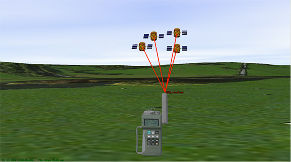
There are various types, and use-cases, of pseudolites. In this column we’ll consider the direct-ranging pseudolite, which can be simply considered as a ground-based GPS satellite. If we deploy several pseudolites on the ground, we can imagine that a normal GPS receiver would be able to receive the GPS-standard transmissions and derive a position, just as we would from the space-based satellite transmissions.
The fact that the pseudolites are ground-based introduces us to the first consideration: The locations of the transmitters are no longer described by orbital parameters. Instead of calculating the position of satellites, we need to describe the location of the pseudolites in geographical terms, perhaps with a fixed position described in Earth-centered, Earth-fixed (ECEF) coordinates.
The transmitted navigation data message, which would normally contain almanac and ephemeris information, may now need to contain the geographical position of the pseudolite. Not a problem, but our GPS receivers will need a software upgrade to be able to handle this situation.
The deployment of the pseudolites themselves poses an interesting problem. Imagine a military scenario, where the army is deployed to a region of interest. Navigation warfare is taking place, and GPS is frequently jammed in the region.
High-power pseudolites are deployed to allow the army to navigate despite the jamming, using the same standard-issue GPS receivers that soldiers are familiar with.
The first problem is, having placed your pseudolites in position, how do you know where they are?
You might choose to place your pseudolites at locations that have previously been surveyed, so you know where they are in advance. But this isn’t likely, particularly if you’ve just moved your troops into an unfamiliar area. You might also want to move the pseudolites regularly, as the army moves to new ground. So the pseudolites need to determine their own position, and the easiest way for at pseudolite to determine its own position is with GPS, of course.
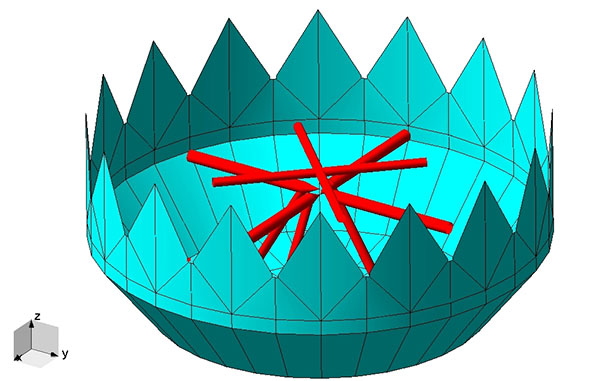
Isn’t this a bit incestuous? If we’re using pseudolites because GPS is jammed, how does the pseudolite get its position? This is why military pseudolites will typically be fitted with some form of anti-jam technology, such as a controlled radiation pattern antenna. This allows the pseudolite to receive GPS satellite signals in the presence of jamming, determine its own position, and transmit that as part of its own navigation message.
So, now that we can get pseudolite locations, the next consideration is: Where should pseudolites be placed?
A-DOP-ting a Good Layout
If you know about GNSS, you’ll be familiar with the concept of dilution of precision (DOP). This is essentially a measure of how accurate your position estimate is likely to be, due to the geometry of the satellites: a good wide spread of satellite positions gives us better accuracy.
Figure 1. Poor satellite geometry, resulting in high DOP. (Image: Michael Jones)Figure 2. Good satellite geometry, resulting in low DOP. (Image: Michael Jones)
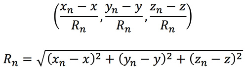
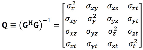
The DOP can be easily calculated by forming a covariance matrix of the geometry, expressed in an appropriate coordinate frame. If (xn, yn, zn) denotes the position of the nth pseudolite, and (x, y, z) the position of the receiver, we can express the unit vectors from the receiver location to the pseudolite location:
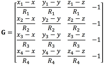
We then form a matrix of these unit vectors:
Finally, we form the covariance matrix from which we can extract the DOP values:
From the elements of this matrix we can determine the various DOP metrics. Let’s concentrate on horizontal DOP (HDOP), given by:
When positioning using GPS satellites, we are blessed with a Walker constellation that generally gives us a nice spread of satellite locations (unless we’re in an urban canyon). On the battlefield, using pseudolites, we do not have the same luxury.
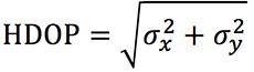
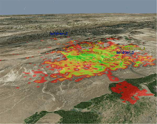
Let’s consider a scenario: a conflict in Helmand province, Afghanistan. An operating base is established at Camp Shorabak, where a pseudolite is operating, and three further pseudolites are deployed in the field. This is shown in figure Figure 3.
Figure 3. Scenario with four pseudolites. (Image: Michael Jones)
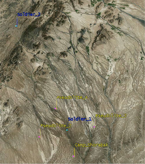
Taking a look at Figure 4, we can see what this means for HDOP. The regions shaded green represent locations where our HDOP is less than 2.5, and the red areas represent an HDOP greater than 50.
Soldier #1 is surrounded by the four pseudolites, which is a pretty nice arrangement: We get an HDOP of around 2.4. But if we now consider soldier #2, located a bit further out, we get a very different picture.
Here we have an HDOP of 64, which is fairly terrible. It’s not really that surprising looking at the geometry — to soldier #2 the pseudolites all appear in a similar direction. Soldier #2 cannot expect to achieve good positional accuracy in this arrangement.
Figure 4. HDOP for the Afghanistan scenario. (Image: Michael Jones)
So getting a good geometric spread of ground-based pseudolite locations could be a bit of a challenge, especially if the operating area is constantly moving and changing. The next thing to think about is getting enough height.
Getting the Height Right
When we perform positioning using GPS, we typically track several satellites, which have a range of elevations. Many GPS receivers will choose to ignore the satellites at low elevations, such as those within 5 degrees of horizontal, because those satellites are generally the least reliable. They may be partially obscured, and subject to more noise and fading.
Ground-based pseudolites all have very low elevations by definition. Unless the terrain is perfectly flat and smooth, pseudolites quickly become obscured. Even with flat ground, pseudolite signals will disappear behind the horizon after a few kilometers.
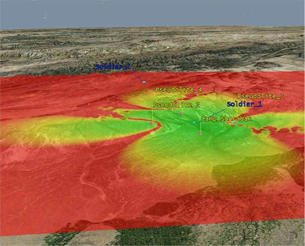
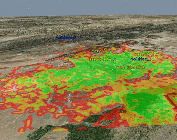
Let’s go back to our Afghanistan scenario again. This time, instead of looking at DOP, let’s look at the geographical coverage of our four pseudolites. Here we’ll assume that our user, the soldier, is 2 meters (m) high, and the pseudolite antennas are mounted at a height of 20m above the ground. That’s pretty high — the army will need to erect some masts.
Figure 5 shows what we get. The green areas are locations where our soldier can see all four pseudolites; yellow three, orange two, and red one. At all other locations, no pseudolite signals can be seen at all. You can quickly see that the range isn’t great — terrain, even small undulations in the ground, is a line-of-sight killer. Add some buildings and trees and the situation gets worse. Reduce the height of our pseudolites below 20m, and the situation gets worse. Soldier #1 can receive three pseudolite signals, but soldier #2 has no hope in this case.
Figure 5. Pseudolite visibility at 20m antenna height. (Image: Michael Jones)
Let’s raise the height of the antennas to a fairly crazy 100m above ground (Figure 6). As expected, we get much better coverage, but soldier #2 still has a problem. To get good signal coverage over any sizable area, you really do need to get those antennas as high as possible.
Figure 6. Pseudolite visibility at 100-m antenna height. (Image: Michael Jones)
Augmenting GPS
Often, we don’t want to rely on pseudolite signals alone. If GPS is available, we clearly want to make use of it, and so we want to use a mixture of both GPS satellites and pseudolites. Consider working in a region of sporadic GPS reception, such as an urban environment or forest. We can usually receive a couple of good GPS satellites, but we also need a couple of pseudolites to help us get a complete navigation solution.
Coming back to one of our original objectives, which is to avoid redesigning the GPS receiver hardware, we need to make sure that our receivers can receive and process both GPS satellite signals and pseudolite signals simultaneously. To achieve this, we can decide to make our pseudolites transmit GPS-standard signals, and make use of unassigned spreading codes to essentially create new satellites in the constellation.
But we quickly run into a problem. GPS satellites are always a distance of around 20,000 kilometers away, and the received signal strength is also fairly constant: around –158.5 dBW. This is a very small signal, as we all know, sitting well below the noise floor. When we suddenly bring high-power pseudolites into the mix, we have quite a nasty problem to deal with.
Near, Far, Wherever You Are
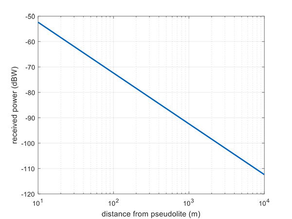
Let’s say, for argument’s sake, we have a pseudolite transmitting with a power of 1 watt. Conducting a basic link budget analysis gives us the plot below and suggests that, at a distance of 10 km from the pseudolite, we can expect to receive the signal at around –112 dBW. This is way above our GPS satellite signal level, but might be manageable by a receiver. Now consider a receiver at a distance of 100 m from the transmitter: we receive a power of –72 dBW, which is huge.
In our quest to augment GPS and make it more robust, we have in fact created a GPS jammer, and achieved exactly the opposite. As with any radio communications link, the received power is extremely sensitive to the distance (varying with the square of distance). In pseudolite terminology, this is known as the near/far problem.
Figure 7. Theoretical received power for a 1-W pseudolite, under ideal conditions. (Figure: Michael Jones)
The near/far problem has given engineers headaches for quite some time. Essentially, the problem comes down to: How can our GPS receivers handle such a massive dynamic range of expected signals? Especially if our objective is to avoid modifying the GPS receiver hardware, if at all possible.
How can a receiver handle the high power of a close-up pseudolite, which is to all intents a jammer, whilst simultaneously receiving the tiny GPS satellite signals from space? Various solutions have been proposed over the years, but one of the current favorite techniques involves pulsing the pseudolite signal.
The idea, then, is to only turn on the pseudolite periodically, essentially applying a duty cycle to the transmission. If a pseudolite isn’t transmitting, it can’t interfere with the normal GPS signals. There are a couple of things to take into consideration here:
What should the pulse duty cycle be, to enable both satellites and pseudolites to be tracked?
How does the GPS receiver behave when presented with alternating large and small signals?
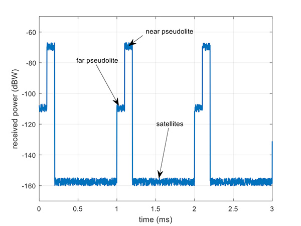
A mathematical analysis of duty cycle effects is beyond the scope of this column, but consider Figure 8 for a qualitative view. Here we have two pseudolites operating alongside GPS satellites. The duty cycle chosen here is for the pseudolite to be operational for 10% of a 1 millisecond integration period. This gives enough time, when the pseudolite is not transmitting, for the low-level GPS satellites to be tracked.
The second pseudolite, which is closer and therefore higher power, transmits for a further 10% slot after the first pseudolite. You can see that each additional pseudolite eats into the time available for tracking GPS satellites, and degrades the signal-to-noise ratio. There are some tricks you can play, such as transmitting multiple pseudolites at the same time if you know they will be similar power levels, but it can get complicated.
Figure 8. Received power versus time, for a pulsed pseudolite scenario. (Figure: Michael Jones)
The Importance of Gain Control
How the receiver copes with the large differences in received power level depends largely on the design of the RF front-end in the receiver. Most GPS receivers will have a certain amount of automatic gain control (AGC), which is a feedback loop designed to keep power levels constant. Many GPS receivers, though, simply aren’t designed with enough AGC to handle pseudolite-level signals (think GPS jammers again).
Military receivers, though, tend to have greater RF handling capabilities, and more bits in the ADC, so are better-suited to the situation. It is then a question of making sure the AGC loop responds in an appropriate time, compared to the duty cycle of pulses.
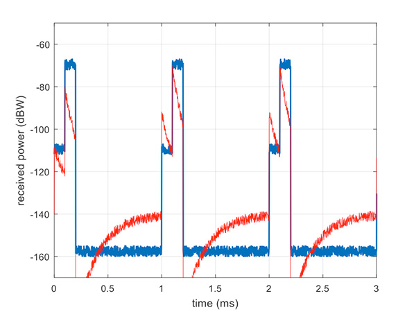
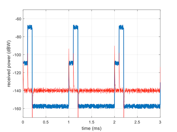
Figure 9 illustrates a slow AGC response, which is not particularly suitable. Compare this with Figure 10, where we have a fast AGC response, quickly adapting to the switches in power level. A receiver with this characteristic will be better able to track both pseudolite and satellite signals.
Figure 9. Pulsed pseudolites with slow AGC response (in red). (Figure: Michael Jones)Figure 10. Pulsed pseudolites with fast AGC response (in red). (Figure: Michael Jones)
Airborne Pseudolites
If you’ve read this far, you’ll now know that the main problems with ground-based pseudolites are lack of good geometry, signal blocking by terrain, and the horrendous near/far issues. Wouldn’t it be nice if we could raise the pseudolites to a really high altitude, and all these problems would go away? Wait, that’s the GPS satellite constellation!
Ok, let’s not put them that far up. But how about carrying pseudolites on high-altitude airborne platforms instead? Great idea, and that’s why this is a current thread of defense activity in various countries. High-altitude long-endurance (HALE) or HAPS (high-altitude pseudo-satellite; the clue is in the name) unmanned platforms can be used to carry pseudolites at high altitude.
This solution can provide excellent coverage, the pseudolites can be repositioned as necessary, and the near/far problem is also far less pronounced.
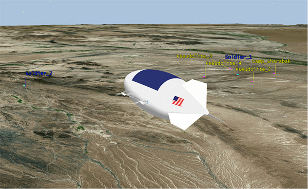
I leave you once again with our Afghanistan scenario, from the point of view of a high-altitude airship at 18,000 meters.
Figure 11. High-altitude platform, potentially carrying a pseudolite at 18,000 m. (Image: Michael Jones)
The U.S. Army continues to expand the use of DT Research’s DT311 series of ultra-rugged tablets into additional army facilities to support training missions and other logistics. In 2016, the U.S. Army awarded DT Research three rugged tablet contracts.
DT Research is a designer and manufacturer of purpose-built computing solutions for vertical markets. The company is headquartered in Silicon Valley, California, with offices in China and Taiwan.
“We are honored to have the U.S. Army choose our rugged tablets again,” said Daw Tsai, president of DT Research. “The U.S. Army has strict requirements for advanced durability, powerful computing, robust connectivity, and fully integrated data capture options for the rugged tablets they use. We are proud to meet these high standards and deliver a specialized tool that will serve the U.S. Army well in their diverse environments.”
LizardTech, a provider of software solutions for managing and distributing geospatial content, has received Certificates of Networthiness (CoN) for GeoExpress 9.x and Express Server 9.x from the U.S. Army Network Enterprise Technology Command (NETCOM).
The CoN signifies that GeoExpress and Express Server are configured to the current Army Golden Master (AGM) baseline and comply with all U.S. Army and Department of Defense (DoD) standards for security, compatibility and sustainability.
A CoN is required for all enterprise software products in the Army Enterprise Infrastructure Network and applies to the U.S. Army as well as National Guard, Army Reserve and DoD organizations using the Army network.
GeoExpress is LizardTech’s flagship software product, enabling geospatial professionals to manipulate digital satellite/aerial image and lidar data and compress them to industry-standard MrSID or JPEG2000 files for easy and cost-effective processing, storage and transmission.
Express Server software is the LizardTech solution for high-performance cataloguing, delivery and publication of geospatial data that lets users access geospatial data on any device with any connection.
“Receiving Certifications of Networthiness for our most recent geospatial software products is a significant achievement and a testament to LizardTech’s continued engagement with the U.S. Army and other U.S. DoD user communities,” said Terry Ryan, LizardTech federal government sales manager. “These CoNs give our users confidence that LizardTech solutions will meet their IT safety and stability requirements, and we look forward to supporting our users at home and abroad.”
The current CoN applies to all 9.x releases of the GeoExpress and Express Server software. LizardTech has pursued and received CoNs for earlier versions of GeoExpress and Express Server, demonstrating a long-term commitment to ensuring U.S. Army forward-deployed personnel have rapid access to geospatial imagery and related data when and where they need it.
Unmanned tactical wheeled vehicles for logistics and route clearance missions provide a significant force protection advantage — removing personnel from targeted vehicles, extending standoff distance from explosives, and empowering a single operator to simultaneously supervise multiple unmanned assets in convoy. This article discusses some of the enabling technologies and the motivations behind them, for safer and more efficient logistics and route clearance operations in a tactical environment.
By John Beck
Unmanned ground vehicles (UGVs) that can semi-autonomously operate over complex terrain represent a promising technological enabler for effective logistics supply and route clearance functions.
Oshkosh Defense has developed autonomous systems for tactical wheeled vehicles (TWVs), working closely with government agencies on autonomous appliqué systems with developed tactics, techniques and procedures that together offer a more efficient and less perilous means to perform critical missions in theater.
The system is designed to be unobtrusive, so that the host platform retains its original mobility, payload capacity, survivability (minimal impact to armor) and manual operation. By upgrading existing fleet vehicles with the capability for unmanned operation, the TerraMax UGV technology can economically and innovatively deliver force protection and force multiplication advantages.
MOTIVATION
Improvised explosive devices (IEDs) pose one of the greatest threats to today’s ground forces carrying out logistics missions in hostile environments. While the up-armoring of tactical vehicles has been effective in reducing casualties, the warfighter remains at risk to the ever-increasing net explosive weights. By fielding UGVs, militaries will be able to remove personnel from TWVs and mitigate the danger of armor overmatch.
To increase efficiency of a reduced force structure, UGVs will serve as force multipliers, enabling a warfighter in a protected vehicle to supervise the coordinated operation of multiple UGVs from a safe standoff distance. These UGVs will be able to operate for extended periods of time, during day and night, and through dust and adverse weather conditions without fatigue or loss of awareness. UGVs will precisely maintain vehicle separation, enabling greater security, improved efficiency and fewer collisions.
Environment Drives Design. To be sustainable in theater, unmanned TWVs must equal their manned counterparts in performance, reliability and mobility in austere tactical environments. For the purposes of overcoming complex terrain, prevailing TWVs are engineered to be capable of feats such as fording 1.5 meters of water and traversing 60% gradients and 30% side slopes.
In addition, these vehicles are expected to operate across broad temperature extremes in dusty, sandy or muddy environments, enduring all manner of precipitation, vegetation and weather conditions. The stringent operational requirements of expeditionary forces influence both individual component selection and overall system design for manned vehicles; the same is true for an unmanned appliqué complement, which must be capable of interpreting and operating in these harsh and complex environments.
ENABLING FULL MOBILITY
TerraMax UGVs are actuated by a tightly integrated drive-by-wire system enabling precise vehicle control using MIL-STD system components to ensure reliability and durability in a tactical environment. It is a safety-critical system that integrates with relevant vehicle components, including steering, engine, brakes, transmission and auxiliary driving functions (such as the central tire inflation system, drive line locks and engine braking), preserving the broad mobility characteristics of the host platform.
The drive-by-wire system both enables higher level robotic control functionality and provides independent benefits in the form of advanced driver assistance system (ADAS) features to benefit manual driving, reducing accidents and collisions.
To facilitate detecting errors absent in an in-vehicle driver’s intuition, the drive-by-wire system communicates with core vehicle diagnostic sensors. It also utilizes add-on sensors that enable monitoring of vehicle and auxiliary subsystem attributes such as hydraulic and pneumatic pressures, ambient and local temperatures, fuel and fluid levels, battery charges and power usage.
All of this data is accessible from the control interface. In addition, threshold values are configured for each monitored sensor such that an operator will be advised if any components exceed warning or critical levels. This ensures that severe conditions do not go unnoticed by an operator, who could be at a distance beyond direct line of sight and may be preoccupied or otherwise unable to dedicate full attention to monitoring multiple UGVs downrange.
Perception Sensors. The TerraMax UGV sensor suite (Figure 1) uses multiple sensor modalities to provide robust sensing capability. The primary sensor for analyzing terrain and obstacles is the high-definition (HD) laser detection and ranging (LADAR), with 64 scanning lasers sweeping 360 degrees.
Figure 1. Sensor suite aboard TerraMax UGV.
In addition, radars are positioned around the vehicle to detect moving obstacles such as other vehicles. Wide-angle cameras are also positioned around the periphery to give a remote operator the ability to visually check vehicle surroundings.
A navigation solution using GPS and an inertial navigation system (INS) supports the ability to drive accurately even with limited GPS signal availability. On the roof facing forward are two cameras used for teleoperation of the vehicle: a wide dynamic range (WDR) camera for daytime use and a short wavelength infrared (SWIR) camera for night operations.
Perception Software. The TerraMax UGV perception software leverages a multi-sensor suite that compensates for the weaknesses of one sensing modality with the strengths of another; for example, relying upon the dust-penetrating ability of automotive radar when LADAR and visible-spectrum camera feeds are obscured.
The perception software uses several modules to interpret the world around it: terrain detection, which assesses roughness of the nearby terrain and informs the selection of appropriate speeds; terrain classification, which distinguishes among foliage, dust or other airborne obscurants and obstacles (Figure 2) and enables traversability appraisals of the surrounding area; and dynamic obstacle detection, which tracks vehicles and dismounts and allows the UGV to exhibit defensive driving behaviors. This software also affords situational awareness and a means for remote supervision of the vehicle by providing processed output for display at the operator control unit.
Figure 2. Perception system display in the TerraMax UGV.
In addition, fused sensor data are combined using novel registration techniques that couple the vehicle’s perception of its surroundings with ground-truth geospatial mapping data to correct for errors in GPS position estimates. This allows the system to be enhanced by, rather than dependent upon, GPS and vehicle-to-vehicle data. Government testing has demonstrated the ability of the TerraMax UGV system to endure complete GPS blackout for more than 19 kilometers with no noticeable impact on mission performance.
Key features of the perception system are:
operable in all environments under all weather and lighting conditions;
installed inconspicuously on the base vehicle and capable of covert modes of operation;
able to deliver reliable system performance under extreme GPS degradation or denial.
Motion-Planning Software. This onboard software takes in an operator’s objectives regarding routing, speed and inter-vehicle spacing as entered during mission planning or on-the-fly. It consequently observes processed sensor data from the perception system and calculates and executes speed and steering commands that guide the vehicle along an optimal path. The motion planning software has been developed with machine learning techniques to emulate smooth human driving behaviors such as avoidance of obstacles and terrain hazards while maintaining appropriate vehicle speed on various terrains.
Key features of the motion planning system are:
intelligent speed and path selection in all terrain, including secondary roads and trails;
capability of sustaining high platform mobility (for example, handling fording and grade climbs);
ability to support high operational tempo (OPTEMPO).
Modes of Operation. When enabled for unmanned operation, a TerraMax UGV can be placed in one of three different modes: semi-autonomous, follower,or tele-operation. The mode selection for each vehicle is controlled from the primary OCU that can be installed in any other tactical or combat vehicle.
In semi-autonomous mode, basic waypoint navigation via GPS coordinates is supported. In addition, mission plans can be created that include information such as check-points, intended vehicle separation distances, speed limits by region, and exclusion zones. These missions are planned from the OCU on a route map that is produced from standard geospatial vector data and predefines the roads on which the UGVs may travel.
This feature, illustrated in Figure 3, allows for on-the-fly mission planning and route changes by selecting “via points” on the road network (similar to a Google Maps functionality) that are automatically connected into a full route plan.
Figure 3. Waypoint navigation.
This requires significantly less effort than manually selecting each individual waypoint for each unmanned vehicle. Once a route has been established, the UGVs traverse the assigned road using their fused global position estimates (leveraging GPS signals as well as the sensor-enhanced map registration to stay on the road) and take advantage of the data link between the vehicles to ensure they maintain prescribed leading and following distances.
In follower mode, no predetermined mission plan is required; a manned vehicle such as the command and control vehicle (C2V) is simply designated as the leader by the operator, and the unmanned vehicles will follow anywhere on the roadway (while still performing intelligent road-keeping and obstacle detection). Two modes of leader tracking are supported: coordinate-based and direct observation.
In the primary mode of coordinate-based following, the lead vehicle transmits its GPS-based position to the follower via the radio data link. The follower vehicle correlates this position to the route map and subsequently appends a waypoint to its upcoming path that would bring the follower to a position on the road directly behind the leader.
In tele-operation mode, an operator assumes remote control of a single UGV and directly commands vehicle speed, steering and other functions via a rugged handheld controller. The operator has a selection of either live video feeds, or an augmented reality view supported by perception data overlaid on aerial imagery, displayed on the OCU display.
OPERATOR CONTROL UNIT
The operator control unit (OCU)hardware and software (Figure 4) are designed to be installed in any other tactical vehicle, along with a low-cost GPS receiver and radio data link that enables communication with multiple TerraMax UGVs from up to 1 kilometer. The OCU allows a single operator to manage coordinated mission command and control of mixed convoys comprised of manned and unmanned vehicles. Route information and convoy behaviors can be pre-planned, saved, loaded and modified as needed during operations.
Figure 4. TerraMax UGV operator control unit.
Touchscreen and function keys allow rapid input using relevant and contextual menus including configurable preset values. Live position and status of each vehicle is displayed on a zoom-able overhead map, and camera feeds from any of the UGVs may be displayed in a familiar picture-in-picture format.
A distilled version of the perception information can be selectively overlaid, aiding the operator’s situational awareness of the vehicles’ surroundings. Remote control and tele-operation is supported using a ruggedized game-style controller for situations when the operator wants direct control of steering and throttle.
TRAINING
Because pre-deployment training opportunities may be limited and any near-term requirement for highly specialized troops is untenable, ease of skill acquisition is critical. In two warfighter experiments for the U.S. Marine Corps Warfighting Lab’s recent Cargo UGV project, the TerraMax system was demonstrated to be operable by veteran motor transport operators after a three-day training course comprising classroom instruction, a realistic desktop simulation environment, and hands-on exercises with the vehicles.
The capstone experiment integrated two TerraMax UGVs into a manned logistics convoy, which was then subjected to a variety of realistic operational scenarios including unexpected road blocks, simulated IED strikes and night operations. Results showed the novice users were able to successfully complete mission objectives using the unmanned systems.
At the conclusion of each of the warfighter experiments for the Cargo UGV project, operators believed they could comfortably control three to five UGVs from a single user interface without suffering cognitive overload.
CONCLUSION
With onboard sensing and decision-making, these unmanned TWVs can provide a force multiplier by empowering a single operator to simultaneously supervise several unmanned assets traveling in convoy, operating semi-autonomously for extended-duration movements. This advantage is significant because it permits more efficient completion of missions by lowering both risk to, and demand for, ground forces.
The procurement, operations and maintenance costs for a robotic capability on TWVs will also be minimized by modernizing existing fleet vehicles with an appliqué kit, but to become viable in theater operations, unmanned TWVs must be able to contend with the same performance, reliability, and mobility in the austere tactical environments as their manned equivalents.
TerraMax UGV technology can be applied to any tactical vehicle and has already been prototyped on the Medium Tactical Vehicle Replacement (MTVR), Palletized Loading System (PLS), Family of Medium Tactical Vehicles (FMTV) and the Mine Resistant Ambush Protected (MRAP) All-Terrain Vehicle (M-ATV).
TERRAMAX HISTORY
Oshkosh has been developing and fully autonomous UGVs since 2003. Among its several generations:
In the 2005 Defense Advanced Research Project Agency (DARPA) Grand Challenge, TerraMax was one of only five vehicles to complete the entire 132-mile course.In 2007, the TerraMax vehicle was one of 11 qualifiers at the DARPA Urban Challenge.In 2012, a second unmanned MTVR was built to evaluate multiple UGVs supervised by a single operator.In 2013, TerraMax UGV M-ATV demonstrated capabilities for route-clearance missions. (Featured on the June 2016 cover.)
ACKNOWLEDGMENT
This article is based on a technical presentation given at AUVSI xPONENTIAL, May 2016 in New Orleans.
John Beck is chief engineer, Unmanned Systems, at Oshkosh Corporation.
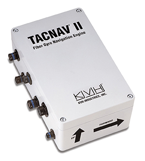
KVH Industries has begun shipping the first order of tactical navigation systems to BAE Systems for a prototype program designed to produce a new fleet of U.S. Army Armored Multi-Purpose Vehicles (AMPVs).
KVH’s TACNAV systems are designed to provide the vehicles with such critical elements as continuous heading and pointing data output and extremely accurate navigation regardless of GPS availability.
Deliveries of the tactical navigation systems are part of a recent purchase order that covers the life of the program, which is expected to run through 2020. The initial order of 34 TACNAV II systems is supporting prototype vehicles, and there is potential for an option for additional systems to support the low-rate initial production (LRIP) of the vehicles.
According to BAE Systems, the $1.2 billion AMPV program is designed to replace the U.S. Army’s Vietnam-era M113s and provide a significant upgrade that increases the service’s survivability, force protection, and mobility while providing for future growth potential.
M113 Armored personnel carrier n Vietnam, 1966. (Photo: U.S. Army)
“KVH is pleased to have been selected by BAE Systems for this important U.S. Army armored vehicle program,” says Dan Conway, executive vice president of KVH’s guidance and stabilization group. “KVH’s tactical navigation solution serves as a crucial resource for navigation and battle management, keeping soldiers safe and out of harm’s way wherever they travel.”
KVH TACNAV is a proven solution that has been serving soldiers for years in numerous armored vehicle programs, with more than 19,000 units fielded worldwide.
KVH’s TACNAV military vehicle navigation systems provide unjammable precision navigation, heading, and pointing data for vehicle drivers, crews, and commanders. KVH’s proprietary fiber optic gyro (FOG) technology is a differentiating factor in enabling the TACNAV systems to provide extremely accurate heading and pointing data, which is crucial for situational awareness.
The Armored Multi-Purpose Vehicle (AMPV) is the U.S. Army’s program to replace the Vietnam-era M113 Family of Vehicles. (Photo: BAE Systems)
The systems feature a compact design and flexible architecture ideal for today’s digital military. In addition, TACNAV is designed to integrate easily with Battle Management Systems (BMS), providing a vital component for effective battlefield management.
TACNAV systems are in use by the U.S. Army and Marine Corps, as well as many allied customers including Canada, Sweden, Great Britain, France, Germany, Spain, Egypt, Botswana, Australia, New Zealand, Saudi Arabia, Taiwan, Romania, Poland, Turkey, Malaysia, Switzerland, South Korea, Singapore, Brazil and Italy.
Virtually all unmanned systems, from drones to autonomous vehicles, use GPS location technology and advanced mapping. As systems evolve, and enemy threats become more sophisticated, new requirements are emerging. The U.S. military is out in front of this trend, developing unmanned autonomous systems at an even faster pace, with more ambitious goals, than the civilian market. This is borne out by several recent tests and announcements, all profiled individually at env-gpsworld-integration.kinsta.cloud. This month’s column rounds up their essential details for a skyview of the burgeoning field.
Publisher’s note: Defense PNT columnist Don Jewell will return next month.
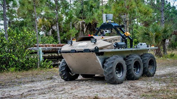
An unmanned Black Hawk delivers an autonomous ground vehicle to a remote site in a demonstration for the U.S. Army of a joint robotic air-ground mission.
Carnegie Mellon University and Sikorsky Aircraft used an autonomous helicopter and an autonomous ground vehicle to demonstrate that ground and air robots can perform complex, cooperative missions. In an October 2015 demo, an unmanned Black Hawk helicopter picked up an unmanned ground vehicle (UGV), flew a 12-mile route, delivered the UGV to a ground location and released it.
The drop-zone collaboration promises to keep warfighters out of harm’s way. For example, this type of robotic mission could avoid warfighters’ exposure to hazardous conditions, such as chemically or radiologically contaminated areas.
The Black Hawk was equipped for autonomous operation by Sikorsky, a Lockheed Martin Co. It delivered a Land Tamer autonomous unmanned ground vehicle from Carnegie Mellon’s National Robotics Engineering Center to a remote site, where the vehicle performed environmental monitoring for potential contamination.
“We were able to demonstrate a new technological capability that combines the strengths of air and ground vehicles,” said Jeremy Searock, NREC technical project manager. “The helicopter provides long-range capability and access to remote areas, while the ground vehicle has long endurance and high-precision sensing.”
Once the helicopter lowered the vehicle to the ground, the Land Tamer drove itself off its transport platform to commence its leg of the mission. The vehicle, equipped with sensors for detecting chemical, biological, radiological or nuclear contamination, then found and surveyed several potentially contaminated sites, autonomously traversing six miles in the process. When the vehicle sensors detected potential contamination, operators were able to switch the vehicle from autonomous operation into a tele-operated mode for a more detailed exploration of the site.
A JPADs pallet lands on target, followed by several others still in the air, during recent testing. (Photo: US Army)
The U.S. Army’s Joint Precision Airdrop System (JPADS) has developed a new capability with a navigation alternative to GPS. In recent tests, JPADS were dropped from planes, and immediately determined their location using optical sensors to compare local terrain with commercial satellite imagery. The new system demonstrated navigation to its intended point, using nothing but imagery to guide it.
JPADS, largely guided by GPS, has already proven its importance in supplying troops with necessary materials and equipment, relying less on vulnerable convoys. However, the new JPADS also works with little knowledge of the aircraft’s location at the drop point.
Dropping critical supplies from the air has allowed the U.S. military to rely less on easily-ambushed truck convoys and helicopter resupply. Exposure to improvised explosive devices (IEDs) and ambushed convoys resulted in more than 3,000 causalities in Afghanistan and Iraq through 2007.
JPADS has proven to be an important tool in the Army’s logistics chain in many scenarios to supply troops with material and equipment in adverse terrain and remote locations when ground lines of communication are not possible or deemed too high a risk.
“This is a huge step forward for aerial resupply,” said Chris Bessette, Draper’s JPADS program manager. “By enabling the system to operate using imagery alone when dropped as high as 25,000 feet above Mean Sea Level and upwards of 20 miles away from the target depending on winds, we can ensure that JPADS is even more versatile so troops receive supplies like fuel, ammunition, food, and water in the safest manner possible.”
In August, U.S. Army Gray Eagle unmanned aircraft took part in manned-unmanned teaming exercises in South Korea, including streaming video and metadata to an AH-64 Apache helicopter while in flight. The MQ-1C Gray Eagle proved its ability to conduct operations in diverse weather condition, according to manufacturer General Atomics Aeronautical Systems (GA-ASI). The Gray Eagle is used by the Army for reconnaissance, surveillance, communications, convoy protection, IED detection and precision weapons delivery.
During the exercise, the Gray Eagle UAS streamed video and metadata via a line-of-sight data link directly to the helicopter from extended distances. The Apache then retransmitted the imagery to a One System Remote Video Terminal (OSRVT), allowing field commanders within the Tactical Operations Center (TOC) to receive both live Gray Eagle streaming video and retransmitted video sent by the Apache. Once the Gray Eagle was airborne, U.S. ground forces passed contact reports and target coordinates to operators in the aircraft’s ground control station. The operators were then able to direct the Gray Eagle’s sensors to positively identify and track the targets.
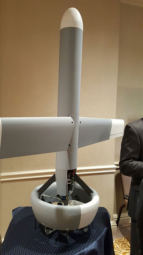
A V-Bat UAV from Martin UAV. Applications include aerial mapping, border patrol, shipboard operations and others.
Worldwide threats will make robotic and autonomous systems’ development important for decades, according to officials speaking at the Unmanned Systems Defense conference late last year.
GPS World’s contributing editor Kevin Dennehy wrote, “Because America has been at war for more than 14 years, unmanned technology has been developing at a rapid rate, perhaps even faster than emerging autonomous commercial systems. The replacement of even manned aircraft has some in the military establishment wary, but others know it’s only a matter of time before most vehicles, surface ships and aircraft are unmanned.”
The Secretary of the Navy said its current manned fighter plane, scheduled to see activity from now until 2037, may be its last to carry an actual human pilot.
The Navy’s Kraken drone munitions delivery system begins its mission underwater,then explodes past the surface to operate in the air. The Air Force also is developing small drones that can be launched and recovered by a larger aircraft after a mission is complete.
An Army initiative called Leader Follower includes rudimentary autonomous convoy operations capability with GPS and base mapping systems, autonomous steering and braking. Army program managers say the program is in staffing, but should be approved in a few months. A full-blown Automated Convoy Operations capability would allow any manned system, including tanks and mobile artillery, to operate autonomously. Last year, the Army and Lockheed Martin successfully demonstrated a driverless line-haul convoy with seven military trucks at speeds up to 40 mph.
Talking about a new generation
Lt. Gen. Michael Williamson, U.S. Army deputy to the assistant secretary of defense for acquisition, said the service is divesting its aging robotics and drone systems, which means future contracts for defense companies. “In 14 years of war, we have rode this equipment pretty hard,” he said. “We believe in modernization, but also looking to buy new systems, which is a new shift in order to gain a competitive advantage over our enemies, who are leveraging unmanned systems.”
The Defense Department recently established the Defense Innovation Unit, based in the San Francisco Bay area, to take advantage of rapid autonomous developments in the Silicon Valley.
Virtually all unmanned systems, from drones to autonomous vehicles, use GPS location technology and advanced mapping. As systems evolve, and enemy threats become more sophisticated, new requirements are emerging.
A surrogate LDUUV is submerged in preparation for a test to demonstrate the capability of the Navy’s Common Control System at the Naval Undersea Warfare Center Keyport in Puget Sound, Washington. (U.S. Navy photo)
In December 2015, the U.S. Navy tested its newly developed Common Control System (CCS) with a submersible unmanned vehicle in underwater missions in Puget Sound, Washington. The CCS successfully demonstrated its capability to provide command and control to a surrogate Large Displacement Unmanned Undersea Vehicle (LDUUV) — an underwater UAV destined for reconnaissance and surveillance missions.
CCS is a software architecture with a common framework, user interface and components that can be integrated on a variety of unmanned systems. It will provide common vehicle management, mission planning and mission management capabilities for the Naval unmanned systems portfolio. Operators used the CCS to transmit pre-planned missions via radio link to the LDUUV’s autonomous controller. In turn, CCS displayed actual vehicle status information to the operators. The vehicle was able to maneuver to the target areas and collect imagery.
“These tests proved that operators could use CCS from a single global operations center to plan, command and monitor UUVs on missions located anywhere in the world,” said Capt. Ralph Lee, who oversees the Navy’s CCS program at Patuxent River, Maryland. “This event also showed us that CCS is adaptable from the UAV (unmanned aerial vehicle) to UUV missions.”
CCS is intended to be compatible across all domains — air, surface, undersea and ground. The Navy initially plans to deploy the CCS on unmanned air vehicles. It will provide common vehicle management, mission planning and mission management capabilities for the Naval unmanned systems portfolio.
In August, U.S. Army Gray Eagle unmanned aircraft took part in manned-unmanned teaming exercises in South Korea, including streaming video and metadata to an AH-64 Apache helicopter while in flight.
Exercise support was conducted from Kunsan Air Base, South Korea, and represent a milestone for the MQ-1C Gray Eagle, proving its ability to conduct operations in diverse weather condition, according to manufacturer General Atomics Aeronautical Systems (GA-ASI).
During the exercise, the Gray Eagle UAS streamed video and metadata via a line-of-sight data link directly to the helicopter from extended distances. The Apache then retransmitted the imagery to a One System Remote Video Terminal (OSRVT), allowing field commanders within the Tactical Operations Center (TOC) to receive both live Gray Eagle streaming video and retransmitted video sent by the Apache. Once the Gray Eagle was airborne, U.S. ground forces passed contact reports and target coordinates to operators in the aircraft’s ground control station. The operators were then able to direct the Gray Eagle’s sensors to positively identify and track the targets.
The Gray Eagle is used by the Army for reconnaissance, surveillance, communications, convoy protection, IED detection and precision weapons delivery.
The U.S. Army’s Armament Research, Development and Engineering Center (ARDEC), located at Picatinny Arsenal in north-central New Jersey, has issued a sources sought notice for technology it can use for a variety of unmanned systems.
The notice says that technologies developed for the Autonomous Unmanned Systems Teaming and Collaboration In GPS Denied Environments program (AUSTC) could be used for small UAS, underwater vehicles and ground vehicles.
The center plans to to “identify, invest, mature and transition revolutionary/game-changing autonomous unmanned sensing technologies.”
“The AUSTC program employs a ‘think-tank’ and modified ‘skunk-works’ approach to identify and determine best path forward for new and game-changing technologies that may be available or in development to achieve U.S. Army RDECOM-ARDEC interest Sensitive Target Site Exploitation (STSE) mission,” the notice reads.
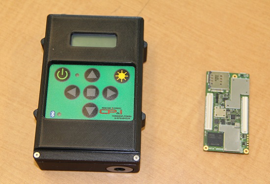
The current WINS form factor (left) sits beside a prototype for the future incarnation.
The Evolution of the Warfighter Integrated Navigation System
A new device is being developed to enable foot soldiers to find their exact location in GPS-denied situations. If satellite signals are blocked by heavy jungle canopy, or because of enemy interference, soldiers — and Headquarters — will still know where they are with the Warfighter Integrated Navigation System (WINS).
WINS will be a compact, wearable navigation device capable of operating either as a standalone system or networked to distribute position location information to other soldier platforms. WINS will extend positioning capability for soldiers in environments where GPS is not available, reducing the effect of GPS interference and enabling integrity monitoring for trusted position reporting.
The technology behind WINS is being developed at the U.S. Army’s Communications Electronics Research Development and Engineering Center (CERDEC) labs. “WINS will be not just one technology; it’s a soldier-worn multi-sensor source incorporating information from GPS, inertials, vision-aided navigation, RF ranging, etc.,” explained John DelColliano, chief for CERDEC’s PNT Branch, which falls under CERDEC’s Command, Power and Integration Directorate (CP&I).
“All these will tie in to making a more robust navigation system, so if you’re in a situation where GPS fails, you can have other things to back you up.” For instance, inertial sensors will calculate an offset from the last-known GPS location using footsteps taken, speed, acceleration and time.
“The bottom line is that the soldier, without having to do any extra work on his own, will have a navigation system on his person that will provide him with a solution that he can count on when he needs it,” DelColliano said.
WINS is expected to help eliminate dependence on vulnerable commercial receivers. It will improve positioning in GPS-degraded environments, enduring some jamming and providing positioning indoors and in urban areas. It will enable soldier-based cooperative engagements and provide trusted dismounted soldier position through integration with Selective Availability Anti-Spoofing Module (SAASM) GPS receivers and redundant navigation sensors.
“CP&I’s PNT branch has worked on these individual technologies for many years, but we’ve always had the vision of an integrated solution,” DelColliano said. “That’s where we are today. It makes the most sense for what the soldier is going to need in the battlefield.” With a WINS-equipped solder, DelColliano said, “We’ll be able to know where he is and at what time, and we’ll be able to track if something happened to him. This capability will also enable our forces to be more mobile and maneuverable. It allows the commander and HQ to see where each squad is.”
As part of a technology demonstration program at Fort Dix, N.J., WINS is being developed under an incremental build process as researchers consider what functionality should be incorporated. The engineering specifications for WINS are expected to be transferred to Program Executive Office, Intelligence and Electronic Warfare & Sensors by 2017, and from there eventually be made available to soldiers.
Future WINS capabilities
The final version of the WINS will have the following capabilities:
Military GPS for a protected signal and anti-jam capability on the soldier.
Inertial measurement unit for soldiers to track their location.
RF ranging using a radio or radio-like device to communicate between soldier-worn nodes and determine the range between soldiers, computing positions through triangulation relative to GPS.
Vision-aided navigation using the same kind of camera as in a cell phone, which is ideal for SWaP-C (size, weight and power compliance), to help navigate by tracking the soldier’s motion through an environment.
 The U.S. Army is soliciting proposals for research, development, design and testing that directly supports battlefield technologies in the area of positioning, navigation and timing (PNT).