Tag: unmanned aerial vehicle

  • Who will survey?

    Who will survey?

    Matteo Luccio
    Luccio

    “Nothing can remain immense if it can be measured,” Hannah Arendt wrote in 1958 in The Human Condition. This could be the guiding inspiration for any geodesist or surveyor throughout history. In about 240 B.C., Eratosthenes became the father of geodesy by ingeniously measuring Earth’s circumference using the Sun, a well, a vertical column, the distance a camel caravan traveled from Syene to Alexandria and some basic mathematics. His estimate of 46,000 kilometers was 16% too large but remarkably close considering that he lacked any modern measuring tool. (For a great account of this epic feat, see John Noble Wilford’s The Mapmakers.)

    Geodesy, a branch of applied mathematics, is concerned with accurately measuring and understanding three of Earth’s fundamental properties: its geometric shape, its orientation in space, and its gravity field. Earth’s true shape varies from the mathematically smooth surface of an ellipsoid due to local differences in its density that cause variations in the strength of the gravitational pull, in turn causing regions to dip below or bulge above a reference ellipsoid.

    This undulating shape is the geoid, which geodesists have defined as the three-dimensional surface along which the pull of gravity is a specific constant. It serves as the zero-level surface for height measurements globally, and all GNSS are pegged to it. It is a hypothetical surface that essentially represents an extension of the idealized mean sea level over (actually, mostly under) Earth’s land surface. Unlike the surface of the oceans, however, it is unaffected by wind, waves, the Moon, or forces other than Earth’s gravity.

    Surveyors are content with measuring much smaller portions of Earth’s surface, from single lots to national boundaries. Unlike Eratosthenes, they work with the latest fruit of modern science and technology — including GNSS receivers, robotic total stations, inertial measurement units, lidar, other sensors and unmanned aerial vehicles — and can measure distances with millimeter precision.

    When I started in this business a little more than 20 years ago, we used to group GPS receivers by accuracy into three buckets: consumer grade, resource/mapping grade and survey grade. As accuracy has increased for all GNSS receivers, the boundaries between those categories, especially between mapping and surveying, have blurred. Additionally, we now have way more GNSS satellites — in some parts of the world, as many as 70 are in view at one time — and a panoply of public and private, ground-based and satellite-based corrections services.

    So, surveyors have a growing set of tools, and they are constantly getting more accurate and more user-friendly.

    Now, let me throw another number in the mix: 66. That is the average age of surveyors in the United States. In the short run, employment for surveyors hinges in part on the vagaries of the economy. In the long run, however, population growth and climate change will force large investments in infrastructure. On most construction sites, the first to arrive and the last to leave are the surveyors. We know what their tools are, but who will they be?

  • SPH Engineering announces bathymetric drone solution

    SPH Engineering has launched a new product to make bathymetric surveys of inland and coastal water.

    The system — an unmanned aerial vehicle (UAV) integrated with an echo sounder — is time- and cost-efficient. It is suitable for mapping, measuring and inspecting tasks as well as environmental monitoring.

    The system allows field workers to collect data with high accuracy quickly. It is easily transported, quickly deployed and twice as cost-efficient as traditional methods.

    The UAV/echo sounder system can be operated in hard to reach locations, and unsafe or hazardous environments. Locations not reachable by foot or that are dangerous for a human (steep coasts, mining pits, contaminated waters, terrain obstacles, etc.) as well as waters of ponds, lakes, and canals can be reached by the drone.

    “Since autumn 2018 we have been getting bathymetry-related requests,” said Lexey Dobrovolskiy, CTO of SPH Engineering. “Analyzing about 150 inquiries, we have come to the conclusion that a drone-based solution could open a new business opportunity for drone service companies to do bathymetry surveys of coastal and inland water, especially those for industrial needs.

    “Compared with a standard approach using a boat or an unmanned surface vehicle, a drone could save a lot for its user,” Dobrovolskiy said. “An echo sounder itself could be integrated into a client’s drone with no need to purchase additional equipment. Moreover, it is small and easy to transport and operate. At the same time, such research method guarantees data accuracy and employee safety.”

  • Riegl launches lightweight airborne lidar for UAVs

    Riegl launches lightweight airborne lidar for UAVs

    The miniVUX-2UAV airborne laser scanner. (Photo: Riegl)
    The miniVUX-2UAV airborne laser scanner. (Photo: Riegl)

    The Riegl miniVUX-2UAV is a lightweight airborne laser scanner designed specifically for integration with unmanned aerial vehicles and systems.

    Riegl added the new miniaturized UAV sensor to its portfolio of professional solutions for UAV-based surveying.

    The sister type of the miniVUX-1UAV sensor, the miniVUX-2UAV offers 100 kHz and 200 kHz PRR. With the 200-kHz PRR, the sensor provides up to 200,000 measurements per second, and thus a dense point pattern on the ground for UAV-based applications that require the acquisition of small objects.

    The Riegl miniVUX-2UAV makes use of Riegl waveform lidar technology, allowing echo digitization and online waveform processing. Multi-target resolution is the basis for penetrating dense foliage, and the wavelength is optimized for the measurement of snowy and icy terrain.

    In addition to the stand-alone version of the miniVUX-2UAV, Riegl also offers fully-integrated solutions.

  • New multi-rotor UAV can lift 200 pounds

    New multi-rotor UAV can lift 200 pounds

    Mobile Recon Systems is offering an unmanned aerial vehicle that can lift more than its own weight.

    At 78 pounds, the Dauntless multi-rotor UAV has lifted an additional payload of 100 pounds as a tethered quadcopter, the company said. It is designed to lift more than 200 pounds as an octocopter, with a generator-powered flight time of several hours.

    Photo: Mobile Recon Systems
    Photo: Mobile Recon Systems

    “Drones have proven to be great for videography. But uses beyond that have been limited by low lift capacity, limited flight time and narrow functional capability,” said Mobile Recon Systems founder Mike Dowell. “With the Dauntless, that is no longer the case.”

    Not only can the Dauntless carry up to 160 pounds of supplies in a climate-controlled transport box, it is a multi-functional platform. It can be outfitted with sensors, radiation detectors, radar, weather stations, multi-spectral, thermal and infrared cameras, and other devices. It can perform eight or more different functions at once. Plus, users can easily swap or combine devices to meet their needs.

    Those capabilities enable this model to deliver high value services previously out of reach for UAVs, the company said.

    “The Dauntless is ideal for border and perimeter security, as well as natural disaster response, medical emergency first response, routine inspections and aerial analysis, and mapping,” Dowell said. “With its lift capacity, it can carry high-end lidar and cameras, as well as supplies. Our flexible platform offers a myriad of possibilities.”

    To illustrate, the Dauntless can carry an MSOP and four multi-axis gimbals, mounted on top and bottom, to accommodate optical, thermal and multispectral cameras, including a RED Epic. high-end digital camera. These can simultaneously capture multiple types of images from below, front, overhead, right and left of the flying platform.

    The Dauntless has a full 3K (military-grade) carbon-fiber body and titanium and aircraft aluminum frame. The propellers are carbon fiber, and are safely surrounded by the body. It is waterproof and sandproof.

  • FAA surveys commercial drone operators

    FAA surveys commercial drone operators

    If you’ve registered a commercial drone, the U.S. Federal Aviation Administration (FAA) wants to hear from you.

    On June 19, the FAA sent a questionnaire to everyone who has registered a commercial drone – more formally, an unmanned aircraft system (UAS) — for anything but recreational or hobby use.

    Most of these owners fly their drones for commercial purposes, but the survey population also includes government departments and other users.

    Hobbyists are not included in this survey.

    The goal is to collect information on drone flight activities under the FAA’s small drone rule (Part 107), data that will help the FAA improve the services it delivers to the UAS community. Responses to the questionnaire are voluntary and entered 100 percent electronically.

    The survey will take about 10 minutes to complete.

    The questions include areas such as number of drones registered, number and types of missions completed in 2017, primary locations where the operator flies and types of waivers requested. The survey also asks how operators want to get information about drone-related issues from the FAA, and how satisfied they are with the news channels they use now

    The questionnaire is completely anonymous, so responses cannot be attributed to an individual.

    If the questionnaire is still sitting on your computer or mobile device, the FAA wants —  and needs — your input.

  • LTE cellular steers UAV: Signals of opportunity work in challenged environments

    No GPS? No Problem!

    Long-term evolution (LTE) cellular signals can be exploited for accurate and resilient autonomous vehicle navigation in the absence of clear GNSS signals. Simulation and experimental results demonstrate that GPS-like performance can be achieved in the absence of GPS signals when cellular pseudoranges aid an inertial navigation system.

    By Zaher M. Kassas, Joshua J. Morales, Kimia Shamaei, and Joe Khalife

    Navigation systems onboard today’s vehicles mainly rely on integrating global navigation satellite system (GNSS) receivers with an inertial navigation system (INS). As vehicles approach full autonomy, requirements on the accuracy and resiliency of the vehicle’s navigation system become ever more stringent.

    Besides the known limitations of GNSS indoors and in deep urban canyons, recent cyber attacks on GNSS signals (jamming and spoofing) are exposing an alarming vulnerability, necessitating alternative and complementary navigation systems when GNSS signals become unavailable or untrustworthy.

    When GNSS signals become unavailable, the errors of the INS’s navigation solution diverge, and the divergence rate is dependent on the quality of the inertial measurement unit (IMU). Such diverging errors compromise the required safe and efficient operation of autonomous vehicles (AVs).

    Two conflicting considerations arise in the design of an AV’s integrated navigation system: high accuracy and low size, weight, power and cost (SWaP- C). Current trends to supplement an autonomous vehicle’s navigation system in the inevitable event when GNSS signals become unusable are traditionally sensor-based, such as cameras and lasers.

    However, such sensors could violate SWaP-C constraints and may not function properly all the time, in all weather conditions. Recently, research in navigation via signals of opportunity (SOPs) has revealed their potential as an attractive source for navigation in GNSS-challenged environments. SOPs are ambient radio signals, which are not intended as positioning, navigation and timing sources: cellular, Wi-Fi, AM/FM, digital television, Iridium satellites and so on. SOPs are practically free to use and could alleviate the need for expensive and bulky aiding sensors.

    Among different SOPs, cellular signals are particularly attractive due to their inherent characteristics:

    • Abundance: Cellular signals base transceiver stations (BTSs) are plentiful.
    • Geometric diversity: The cellular system configuration by construction yields favorable BTS geometry, unlike certain terrestrial SOPs such as digital television, which tend to be co-located.
    • Large bandwidth: Cellular signals have a bandwidth up to 20 MHz, yielding accurate time-of-arrival (TOA) estimation.
    • High received power: The received carrier-to-noise ratio (C/N0) from nearby cellular BTSs is commonly tens of dBs higher when compared to GNSS signals.

    While cellular SOPs are lucrative to exploit for navigation purposes, a number of challenges must be first addressed, since such signals were never intended for navigation purposes. TABLE 1 compares GNSS space vehicles (SVs) and cellular BTSs with respect to relevant navigation attributes. Unlike GNSS SVs whose positions and clock errors are transmitted to the receiver in the navigation message, cellular BTSs do not transmit such information. Therefore, the receiver must either estimate these quantities in a stand-alone fashion or have access to a database (cloud-hosted) that is crowdsourcing this information from multiple nearby receivers.

    The first strategy is analogous to the simultaneous localization and mapping (SLAM) problem in robotics, while the second strategy could be achieved by deploying multiple receivers, whether vehicle-mounted or affixed on dedicated stations.

    This article discusses relevant cellular code division multiple access (CDMA) and long-term evolution (LTE) signals that could be exploited for navigation. The article also presents a specialized software-defined receiver (SDR) called Multichannel Adaptive TRansceiver Information eXtractor (MATRIX), developed at the Autonomous Systems Perception, Intelligence, and Navigation (ASPIN) Laboratory at the University of California, Riverside. MATRIX is capable of producing pseudorange observables to cellular CDMA and LTE BTSs. We also present a radio SLAM approach for AV navigation via a tightly-coupled cellular-aided INS framework. Simulation and experimental results demonstrate ground vehicles and unmanned aerial vehicles (UAVs) navigating with cellular signals in the absence of GNSS signals.

    CDMA SIGNALS

    CDMA is at the heart of third-generation (3G) wireless communication systems, which use orthogonal and maximal-length pseudorandom noise (PN) sequences to enable multiplexing over the same channel. The sequences transmitted on the forward link channel, from BTS to receiver, are known. By correlating the received cellular CDMA signal with a locally generated PN sequence, the receiver can estimate the TOA and produce a pseudorange measurement. In a cellular CDMA communication system, 64 logical channels are multiplexed on the forward link channel: a pilot channel, a sync channel, seven paging channels, and 55 traffic channels.

    The receiver uses the pilot signal to detect the presence of a CDMA signal and synchronize its locally-generated short code. The sync and paging channels are used to provide time and frame synchronization to enable the receiver to register in the network. All forward-link signals are spread at 1.2288 MHz by a 32,768-chip PN sequence called the short code. To distinguish the received data from different BTSs, each station uses a shifted version of the short code. This shift, known as the pilot offset, is unique for each sector of each BTS and is an integer multiple of 64 chips; hence, a total of 512 pilot offsets can be realized.

    The goal of a cellular CDMA navigation receiver is to acquire and track the signal parameters, namely the code phase and the carrier phase. To this end, such a receiver consists of three main stages: signal acquisition, signal tracking and message decoding. The pilot channel is used for signal acquisition and tracking. In fact, the pilot channel is dataless: only the short code is transmitted. This enables longer integration periods. A search in time and frequency in the acquisition stage obtains a coarse estimate of the TOA and the Doppler frequency.

    Next, these parameters are tracked and their estimates are refined via tracking loops. Similar to a GPS receiver, a phase-locked loop (PLL) and a carrier-aided delay-locked loop (DLL) are used to track the carrier and code phase, respectively. Finally, the sync and paging channels are decoded for timing and data association purposes. FIGURE 1 illustrates the three stages of the cellular CDMA module of the MATRIX SDR, implemented as LabVIEW virtual instruments (VIs), and the front panel corresponding to each stage.

    LTE SIGNALS

    LTE has become the prominent standard for fourth-generation (4G) communication systems. Its multiple-input, multiple-output capabilities allow higher data rates compared to previous wireless standards. The high bandwidth and ubiquity of LTE networks make LTE signals attractive for navigation. In LTE Release 9, a broadcast positioning reference signal (PRS) was introduced to enable network-based positioning capabilities within the LTE protocol.

    However, PRS-based positioning suffers from a number of drawbacks:

    • The user’s privacy is compromised since the user’s location is revealed to the network.
    • Localization services are limited only to paying subscribers and from a particular cellular provider.
    • Ambient LTE signals transmitted by other cellular providers are not exploited.
    • Additional bandwidth is required to accommodate the PRS, which caused the majority of cellular providers to choose not to transmit the PRS in favor of dedicating more bandwidth for traffic channels.

    To circumvent these drawbacks, user equipment-(UE)-based positioning approaches, which exploit the existing reference signals in the transmitted LTE signals, have been explored.

    LTE Frame Structure. LTE uses orthogonal frequency division multiplexing (OFDM) to transmit signals. In OFDM, the transmitted symbols are first parallelized into groups of length Nr. Then, to provide a guard band, the resulting signal is zero-padded to a length Nc, which is set to be greater than Nr. Finally, an inverse fast Fourier transform (IFFT) is taken, and the last Lcp elements are repeated at the beginning. TABLE 2 shows the possible values for Nr and Nc in an LTE system.

    The OFDM signals are arranged into blocks called frames. A frame is composed of 10 ms data, which is divided into either 20 slots or 10 subframes with duration of 0.5 ms or 1 ms, respectively. A slot can be decomposed into multiple resource grids and each resource grid has numerous resource blocks. Then, a resource block is broken down into the smallest elements of the frame, namely resource elements. The frequency and time indices of a resource element are called subcarrier and symbol, respectively.

    LTE Reference Signals

    There are three possible reference sequences in a received LTE signal that can be exploited for navigation.

    Primary synchronization signal (PSS). The PSS is transmitted in symbol 7 of slots 0 and 10 of each frame. This signal, which is transmitted on the middle 62 subcarriers, provides symbol timing to the UE. The PSS is expressible in only three different orthogonal sequences, each of which represents a BTS’s (also known as eNodeB) sector ID. This presents two main drawbacks: the received signal is highly affected by interference from neighboring eNodeBs with the same PSS sequences, and the UE can only simultaneously track a maximum of three eNodeBs, which is not desirable in an environment comprising more than three eNodeBs.

    Secondary synchronization signal (SSS). The SSS is transmitted in symbol 6 of slot 0 or 10 of each frame. This signal, which is transmitted on the middle 62 subcarriers, provides frame timing to the user equipment. The SSS is expressible in only 168 different sequences, each of which represents the cell group identifier; therefore, it does not suffer from the aforementioned drawbacks of the PSS. The transmission bandwidth of the SSS is 930 KHz, which is slightly less than the GPS C/A code bandwidth (1.023 MHz). Therefore, navigation with SSS provides comparable results to GPS: low-cost and relatively precise pseudorange information using conventional PLLs and DLLs in an environment without multipath, but low TOA accuracy in a multipath environment.

    Cell-specific reference signal (CRS). The CRS is mainly transmitted to estimate the channel between the eNodeB and the UE. Therefore, it is scattered in both frequency and time and is transmitted from all transmitting antennas. The CRS is known to provide better accuracy in estimating the TOA in a multipath environment due to its higher transmission bandwidth. Since the CRS is scattered across the LTE bandwidth, it is not possible to track the TOA from the CRS using conventional low-complexity DLLs. Several methods can be used to estimate the channel parameters, including the TOA: multiple signal classification (MUSIC), estimation of signal parameters via rotational invariance techniques (ESPRIT) and space-alternating generalized expectation-maximization (SAGE) algorithms.

    LTE Receiver Structure

    The LTE navigation receiver exploits SSS, PSS and CRS, and consists of four stages.
    Acquisition. In this step, the received signal is correlated with the locally generated PSS and SSS signals to obtain the frame start time estimate, Doppler frequency estimate and the eNodeB’s cell ID.

    System information extraction. In LTE systems, the bandwidth can be assigned to different values. The actual value of the bandwidth is provided to the UE by the eNodeB in a block called master information block (MIB). When user equipment enters an LTE network, it starts receiving signals with the lowest possible bandwidth. After obtaining the frame start time, it is possible to convert the LTE signals into frame structure by executing the steps discussed in the LTE Frame Structure section in reverse order. Then, the UE decodes the MIB and obtains the actual bandwidth. The UE can then increase the sampling rate to as high as the signal bandwidth.

    Due to the near-far effect on the PSS signal, it is not possible to acquire all the available eNodeBs in the environment. Each eNodeB provides the list of its neighboring cell IDs to the UE in the system information block (SIB). After obtaining the frame start time and the actual transmission bandwidth, the UE can decode the SIB to obtain the neighboring cell IDs.

    Tracking. The receiver starts tracking the SSS using components of the tracking loop: a frequency-locked loop (FLL)-assisted PLL to track the carrier phase and a carrier-aided DLL to track the code phase.

    Timing information extraction. To overcome the error due to multipath in tracking the SSS, the CRS is used. For this purpose, by knowing the CRS sequence and the received signal, the channel frequency response is first estimated. Then, the channel impulse response is obtained by taking an IFFT of the channel frequency response. Finally, the first peak of the channel impulse response is detected, which represents the line-of-sight TOA.

    FIGURE 2 illustrates the block diagram of the LTE module of the MATRIX SDR and the corresponding LabVIEW VIs.

    CELLULAR-AIDED INERTIAL NAVIGATION

    To correct INS errors using cellular pseudoranges, an extended Kalman filter (EKF) framework similar to a traditional tightly coupled GNSS-aided INS integration strategy is adopted, with the added complexity that the cellular BTSs’ states (position and clock error states) are simultaneously estimated alongside the navigating vehicle’s states (position, velocity, attitude, IMU measurement error states and receiver clock error states). This framework is composed of two modes.

    Mapping Mode. The EKF produces estimates and associated estimation error covariances of both the navigating vehicle and the cellular BTSs’ states (augmented in x) using both GNSS SV and cellular BTS pseudoranges. Between aiding corrections, the EKF produces the state prediction x^– and prediction error covariance P– using INS model and receiver and cellular BTS clocks models. When an aiding source is available, either a GNSS SV or cellular BTS pseudorange, the EKF produces a state estimate update x^+ and associated estimation error covariance P+.

    SLAM Mode. The cellular-aided INS framework enters a SLAM mode when GNSS pseudoranges become unavailable. In this mode, INS errors are corrected using cellular BTS pseudoranges and the cellular BTSs’ state estimates provided from the mapping mode. As the autonomous vehicle navigates, it simultaneously continues to refine the BTSs’ state estimates. FIGURE 3 illustrates a high-level diagram of the cellular-aided INS framework.

    SIMULATION RESULTS

    To evaluate the performance of this cellular-aided INS framework presented, simulations were conducted of a UAV equipped with the MATRIX SDR, navigating in downtown Los Angeles, while exploiting ambient cellular signals. Two navigation systems were employed to estimate the trajectory of the UAV: a traditional tightly-coupled GPS-aided INS with a tactical-grade IMU; and the cellular-aided INS discussed here with a consumer-grade IMU.

    A simulator generated the true trajectory of the UAV and clock error states of the UAV-mounted receiver, the cellular BTSs’ clock error states, noise-corrupted IMU measurements of specific force and angular rates and noise-corrupted pseudoranges to multiple cellular BTSs and GPS SVs.

    The IMU signal generator models a triad gyroscope and a triad accelerometer, each with time-evolving biases that provided sampled data at 100 Hz. GPS L1 C/A pseudoranges were generated at 1 Hz using SV orbits produced from receiver independent exchange files downloaded Oct. 22, 2016, from a continuously operating reference station server. The GPS L1 C/A pseudoranges were set to be available for only the first 100 seconds of the 200-second simulation. Cellular pseudoranges were generated at 5 Hz to four BTS locations, which were surveyed from real tower positions in downtown Los Angeles.

    The UAV’s true trajectory included a straight segment followed by two banked orbits in the vicinity of the four cellular BTSs, shown in FIGURE 4(a). The resulting EKF estimation errors and corresponding three standard deviation bounds for the north and east position of the UAV are plotted in FIGURE 4(b). The navigation solution from using the cellular-aided INS and navigation solution from using only an INS during the 100 seconds GPS pseudoranges were unavailable appear in FIGURE 4(c). The final BTS estimated position and corresponding 95th percentile estimation uncertainty ellipse is shown in FIGURE 4(d).

    We can conclude that when GPS pseudoranges become unavailable at 100 seconds, the estimation errors associated with the traditional GPS-aided INS integration strategy begin to diverge, as expected, whereas the errors associated with the cellular-aided INS are bounded within this 100-second duration of GPS unavailability. Second, when GPS was still available during the first 100 seconds, the cellular-aided INS with a consumer-grade IMU almost always produced lower estimation error uncertainties when compared to the traditional GPS-aided INS integration strategy with a tactical-grade IMU.

    EXPERIMENTAL RESULTS

    To evaluate the standalone LTE navigation performance, two field tests were conducted with real LTE signals in semi-urban and urban environments. In both tests, a ground vehicle was equipped with LTE and GPS antennas and universal software radio peripherals (USRPs). LTE signals were simultaneously downmixed and synchronously sampled via a dual-channel USRP driven by a GPS-disciplined oscillator. The GPS navigation solution served as ground truth. FIGURE 5(a) shows experimental results for a CRS-based and an SSS-based receiver in a semi-urban environment with moderate multipath. The table, FIGURE 5(b), demonstrates the importance of exploiting CRS to alleviate multipath effects. Figure 5(b) shows the experimental results for a CRS-based receiver in an urban environment with severe multipath.

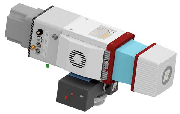
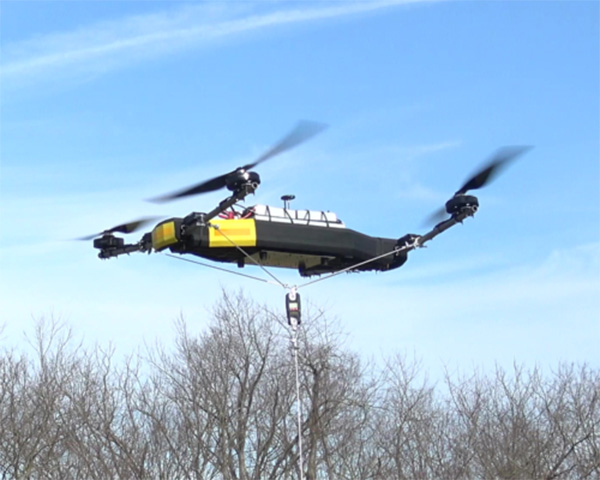
    To evaluate the performance of cellular-aided inertial navigation, a field test was conducted with real cellular signals and an IMU-equipped UAV. The UAV was equipped with three antennas to acquire and track:

    • GPS signals
    • LTE signals from nearby eNodeBs
    • cellular CDMA signals from nearby BTSs.

    Samples of the received signals were stored for off-line post-processing. The LTE and CDMA signals were processed by the MATRIX SDR. FIGURE 6 depicts the experimental hardware setup.

    Experimental results are presented for two scenarios: the cellular-aided INS described in this article, and for comparative analysis, a traditional GPS-aided INS using the UAV’s IMU. The true trajectory traversed by the UAV is plotted in the opening figure (b)-(c), which consists of a GPS unavailability run of 50 seconds, starting at a location marked by the red arrow. The north-east root mean squared errors (RMSE) of the GPS-aided INS’s navigation solution after GPS became unavailable was more than 100 meters.

    The UAV also estimated its trajectory using the cellular-aided INS framework using signals from the two eNodeBs and three cellular BTSs illustrated in opening figure (a) to aid its onboard INSs. The north-east RMSEs of the UAV’s trajectory after GPS became unavailable was 4.68 meters with a final error of 4.92 meters.

    TABLE 3 summarizes the UAV’s RMSEs and final errors.

    CONCLUSION

    Cellular signals can be exploited to navigate in the absence of GNSS signals. Experimental results demonstrated a UAV navigating with a cellular-aided INS using two LTE eNodeBs and three cellular CDMA BTSs achieving GPS-like performance in the absence of GNSS signals. This article is based on IEEE/ION PLANS, ION GNSS+ and ION ITM papers by the authors; see online version.

    This work is supported by grants from the Office Naval Research (ONR) under Grant N00014-16-1-2305 and the National Science Foundation (NSF) under Grant 1566240.

    MANUFACTURERS

    Cellular antennas used were consumer-grade 800/1900-MHz cellular omnidirectional antennas. The UAV and GPS antenna used were DJI with the A3 flight controller. The cellular signals were simultaneously down-mixed and synchronously sampled via two Ettus E-312 USRPs tuned to 1955 MHz (AT&T) and 882.75 MHz (Verizon) carrier frequencies.


    JOSHUA J. MORALES is a Ph.D. student at the University of California, Riverside and a member of the Autonomous Systems Perception, Intelligence, and Navigation (ASPIN) laboratory.

    KIMIA SHAMAEI is a Ph.D. candidate at the University of California, Riverside and a member of the ASPIN Laboratory.

    JOE KHALIFE is a Ph.D. student at the University of California, Riverside and a member of the ASPIN Laboratory.

    ZAHER (ZAK) M. KASSAS is an assistant professor at the University of California, Riverside and director of the ASPIN Laboratory. He received a Ph.D. in electrical and computer engineering from the University of Texas at Austin.

  • Vanilla Aircraft claims record with 56-hour unmanned flight

    The Vanilla Aircraft VA001, a small diesel-powered airplane under development through DARPA (left), flew for 56 hours recently over Las Cruces, New Mexico (right), setting a new world record for flight duration for its weight class. The airplane is designed to ultimately carry a 30-pound payload at 15,000 feet for up to 10 days without refueling. (Images: DARPA)
    The Vanilla Aircraft VA001 flew for 56 hours recently over Las Cruces, New Mexico (right), setting a new world record for flight duration for its weight class. The airplane is designed to ultimately carry a 30-pound payload at 15,000 feet for up to 10 days without refueling. (Images: DARPA)

    On Dec. 2, Vanilla Aircraft‘s VA001 unmanned aircraft system (UAS) completed a world record non-stop, unrefueled 56-hour flight.

    The flight was supported by the technology innovation investments of the U.S. Department of Defense’s Rapid Reaction Technology Office (RRTO) and DARPA-funded efforts through Naval Air System Command (NAVAIR 4.11 – Patuxent River).

    The VA001 10-day Endurance UAS.
    The VA001 10-day Endurance UAS.

    The flight, planned as a 120-hour mission, was ended early because of forecasts of severe icing and range restrictions. However, the airplane landed with enough JP-8 fuel on board for an additional 90 hours of flying, or enough for a total of six days of flight.

    The flight was certified as a world-duration record for combustion-powered unmanned aerial vehicles (UAVs) in the 50-500 kilogram subclass (Fédération Aéronautique Internationale Class U-1.c Group 1). A representative from the National Aeronautic Association was present to witness the record. Moreover, the flight was the fourth-longest for any unmanned airplane and the 11th-longest for an airplane of any type (manned or unmanned, solar or fuel-powered).

    Originating and ending at Las Cruces International Airport, the flight was conducted under the authority of the New Mexico State University UAS test site designated by the Federal Aviation Administration (FAA).

    “This effort represents tremendous and unprecedented coordination among civil, defense, academic, and private industry to bring a heretofore only imagined capability to reality,” said Vanilla Aircraft CEO Rear Adm. Timothy Heely (ret.).

    Small unmanned aerial vehicles (UAVs) are an increasingly important means for military forces — especially small dismounted units — to bring extra communications or intelligence, surveillance and reconnaissance (ISR) capabilities to the field. Current designs, however, offer relatively limited range and flight endurance; additionally, their need for frequent refueling, specialized launch and recovery equipment, and regular maintenance often limit them to flying from fixed bases close to the front lines.

    “This record-breaking flight demonstrated the feasibility of designing a low-cost UAV able to take off from one side of a continent, fly to the other, perform its duties for a week, and come back — all on the same tank of fuel,” said Jean-Charles Ledé, DARPA program manager. “This capability would help extend the footprint of small units by providing scalable, persistent UAV-based communications and ISR coverage without forward basing, thereby reducing personnel and operating costs. We’re very pleased with what the Vanilla team has accomplished.”

    Two VA001 UAVs by Vanilla Aircraft.
    Two VA001 UAVs by Vanilla Aircraft.

    The airplane carried 20 pounds of actual and simulated payload, flying at 6,500 to 7,500 feet above mean sea level (MSL), and was a further step for the VA001 towards demonstrating the system’s objective performance of carrying a 30-pound payload for 10 days at an altitude of 15,000 feet.

    The payload included a NAVAIR-provided relay and operated continuously throughout the flight to demonstrate functionality out to the maximum range.

    The airplane also carried a NASA-provided multispectral imaging payload as a demonstration of Earth science and agricultural remote sensing.

    “The VA001 has transformational potential, providing a scalable aerial system solution without increasing personnel or operating costs,” said co-founder and chief engineer Neil Boertlein. “The ability of a low-cost platform to provide persistent surveillance, battlefield pattern of life, or aerial mesh network relay, in a responsive and robust manner, and without forward basing, does not currently exist.”

    Vanilla Aircraft is also planning a groundbreaking role for the VA001 in commercial applications, especially in agriculture. Vanilla is exploring strategic partnerships and equity financing to expand into this market.

    “The VA001 would be a cost-effective option for widespread and regular low-level surveying,” said co-founder and program manager Jeremy Novara. “We could fill a wide cost and payload-capability market gap between small electric and large military unmanned aircraft, which is perfect for many commercial applications.”

  • Arcturus VTOL UAS deployed with the Mexican Navy

    Arcturus VTOL UAS deployed with the Mexican Navy

    Arcturus-Jump-WArcturus UAV reports the Mexican Navy has deployed its T-20 Jump fixed-wing vertical take-off and landing (VTOL) UAV for unspecified operations in Mexico. The customer took delivery of the VTOL system in March.

    The announcement was made at AUVSI’s Xponential 2016.

    The T-20 Jump is a VTOL variant of Arcturus UAV’s catapult launched T-20 platform. It operates without any special launch or recovery equipment. Gross payload capacity is 60 pounds.

    The Mexican Navy configuration with an electro-optics and infrared (EO/IR) sensor has approximately 15 hours of endurance and a 75-mile data-link range. An EO/IR and EW capable version offers 11 hours of endurance. Mexico has operated a fleet of catapult launch T-20s since 2014.

    Arcturus has proposed the T-20 Jump VTOL platform for MEUAS III, the United States Special Operations Command‘s (USSOCOM’s) worldwide UAS services contract. Arcturus has also proposed a heavy fuel version of the T-20 Jump for the Royal Australian Navy’s Tactical Unmanned Aircraft Program.

  • Australia could replace jet fighters with unmanned combat

    Australian Chief of the Defence Force Mark Binskin said that combat drones could take the place of some Joint Strike Fighters (JSFs).

    A defense white paper states that Australia will buy 72 Joint Strike Fighters to replace current fighter planes “Classic” Hornets, six of which are now flying bombing raids over Iraq and Syria. But it leaves open the possibility of not buying a final squadron of roughly 25 JSFs to make up the 100-strong air combat fleet Australia needs.

    Instead, the white paper states that to replace the newer, current squadron of Super Hornet aircraft from about 2030, alternatives will be “considered.”

    Binskin said the department was keeping an open mind given the rapid improvements in armed drones or unmanned combat aerial vehicles, also known as UCAVs.

  • US military leads autonomous trend

    US military leads autonomous trend

    Virtually all unmanned systems, from drones to autonomous vehicles, use GPS location technology and advanced mapping. As systems evolve, and enemy threats become more sophisticated, new requirements are emerging. The U.S. military is out in front of this trend, developing unmanned autonomous systems at an even faster pace, with more ambitious goals, than the civilian market. This is borne out by several recent tests and announcements, all profiled individually at env-gpsworld-integration.kinsta.cloud. This month’s column rounds up their essential details for a skyview of the burgeoning field.

    Publisher’s note: Defense PNT columnist Don Jewell will return next month.

    Unmanned ground-air collaboration for war-zone delivery

    An unmanned Black Hawk delivers an autonomous ground vehicle to a remote site in a demonstration for the U.S. Army of a joint robotic air-ground mission.
    An unmanned Black Hawk delivers an autonomous ground vehicle to a remote site in a demonstration for the U.S. Army of a joint robotic air-ground mission.

    Carnegie Mellon University and Sikorsky Aircraft used an autonomous helicopter and an autonomous ground vehicle to demonstrate that ground and air robots can perform complex, cooperative missions. In an October 2015 demo, an unmanned Black Hawk helicopter picked up an unmanned ground vehicle (UGV), flew a 12-mile route, delivered the UGV to a ground location and released it.

    The drop-zone collaboration promises to keep warfighters out of harm’s way. For example, this type of robotic mission could avoid warfighters’ exposure to hazardous conditions, such as chemically or radiologically contaminated areas.
    The Black Hawk was equipped for autonomous operation by Sikorsky, a Lockheed Martin Co. It delivered a Land Tamer autonomous unmanned ground vehicle from Carnegie Mellon’s National Robotics Engineering Center to a remote site, where the vehicle performed environmental monitoring for potential contamination.

    “We were able to demonstrate a new technological capability that combines the strengths of air and ground vehicles,” said Jeremy Searock, NREC technical project manager. “The helicopter provides long-range capability and access to remote areas, while the ground vehicle has long endurance and high-precision sensing.”

    Once the helicopter lowered the vehicle to the ground, the Land Tamer drove itself off its transport platform to commence its leg of the mission. The vehicle, equipped with sensors for detecting chemical, biological, radiological or nuclear contamination, then found and surveyed several potentially contaminated sites, autonomously traversing six miles in the process. When the vehicle sensors detected potential contamination, operators were able to switch the vehicle from autonomous operation into a tele-operated mode for a more detailed exploration of the site.

    Non-GPS autonomous aerial delivery

    A JPADs pallet lands on target, followed by several others still in the air, during recent testing. (Photo: US Army)
    A JPADs pallet lands on target, followed by several others still in the air, during recent testing. (Photo: US Army)

    The U.S. Army’s Joint Precision Airdrop System (JPADS) has developed a new capability with a navigation alternative to GPS. In recent tests, JPADS were dropped from planes, and immediately determined their location using optical sensors to compare local terrain with commercial satellite imagery. The new system demonstrated navigation to its intended point, using nothing but imagery to guide it.

    JPADS, largely guided by GPS, has already proven its importance in supplying troops with necessary materials and equipment, relying less on vulnerable convoys. However, the new JPADS also works with little knowledge of the aircraft’s location at the drop point.

    Dropping critical supplies from the air has allowed the U.S. military to rely less on easily-ambushed truck convoys and helicopter resupply. Exposure to improvised explosive devices (IEDs) and ambushed convoys resulted in more than 3,000 causalities in Afghanistan and Iraq through 2007.

    JPADS has proven to be an important tool in the Army’s logistics chain in many scenarios to supply troops with material and equipment in adverse terrain and remote locations when ground lines of communication are not possible or deemed too high a risk.

    “This is a huge step forward for aerial resupply,” said Chris Bessette, Draper’s JPADS program manager. “By enabling the system to operate using imagery alone when dropped as high as 25,000 feet above Mean Sea Level and upwards of 20 miles away from the target depending on winds, we can ensure that JPADS is even more versatile so troops receive supplies like fuel, ammunition, food, and water in the safest manner possible.”

    Unmanned teaming, video-streaming

    In August, U.S. Army Gray Eagle unmanned aircraft took part in manned-unmanned teaming exercises in South Korea, including streaming video and metadata to an AH-64 Apache helicopter while in flight. The MQ-1C Gray Eagle proved its ability to conduct operations in diverse weather condition, according to manufacturer General Atomics Aeronautical Systems (GA-ASI). The Gray Eagle is used by the Army for reconnaissance, surveillance, communications, convoy protection, IED detection and precision weapons delivery.

    During the exercise, the Gray Eagle UAS streamed video and metadata via a line-of-sight data link directly to the helicopter from extended distances. The Apache then retransmitted the imagery to a One System Remote Video Terminal (OSRVT), allowing field commanders within the Tactical Operations Center (TOC) to receive both live Gray Eagle streaming video and retransmitted video sent by the Apache. Once the Gray Eagle was airborne, U.S. ground forces passed contact reports and target coordinates to operators in the aircraft’s ground control station. The operators were then able to direct the Gray Eagle’s sensors to positively identify and track the targets.

    The overall military perspective

    A V-Bat UAV from Martin UAV. Applications include aerial mapping, border patrol, shipboard operations and others.
    A V-Bat UAV from Martin UAV. Applications include aerial mapping, border patrol, shipboard operations and others.

    Worldwide threats will make robotic and autonomous systems’ development important for decades, according to officials speaking at the Unmanned Systems Defense conference late last year.

    GPS World’s contributing editor Kevin Dennehy wrote, “Because America has been at war for more than 14 years, unmanned technology has been developing at a rapid rate, perhaps even faster than emerging autonomous commercial systems. The replacement of even manned aircraft has some in the military establishment wary, but others know it’s only a matter of time before most vehicles, surface ships and aircraft are unmanned.”

    The Secretary of the Navy said its current manned fighter plane, scheduled to see activity from now until 2037, may be its last to carry an actual human pilot.

    The Navy’s Kraken drone munitions delivery system begins its mission underwater,then explodes past the surface to operate in the air. The Air Force also is developing small drones that can be launched and recovered by a larger aircraft after a mission is complete.

    An Army initiative called Leader Follower includes rudimentary autonomous convoy operations capability with GPS and base mapping systems, autonomous steering and braking. Army program managers say the program is in staffing, but should be approved in a few months. A full-blown Automated Convoy Operations capability would allow any manned system, including tanks and mobile artillery, to operate autonomously. Last year, the Army and Lockheed Martin successfully demonstrated a driverless line-haul convoy with seven military trucks at speeds up to 40 mph.

    Talking about a new generation

    Lt. Gen. Michael Williamson, U.S. Army deputy to the assistant secretary of defense for acquisition, said the service is divesting its aging robotics and drone systems, which means future contracts for defense companies. “In 14 years of war, we have rode this equipment pretty hard,” he said. “We believe in modernization, but also looking to buy new systems, which is a new shift in order to gain a competitive advantage over our enemies, who are leveraging unmanned systems.”

    The Defense Department recently established the Defense Innovation Unit, based in the San Francisco Bay area, to take advantage of rapid autonomous developments in the Silicon Valley.

    Virtually all unmanned systems, from drones to autonomous vehicles, use GPS location technology and advanced mapping. As systems evolve, and enemy threats become more sophisticated, new requirements are emerging.

    Underwater UAV for reconnaissance and surveillance

    A surrogate LDUUV is submerged in preparation for a test to demonstrate the capability of the Navy's Common Control System at the Naval Undersea Warfare Center Keyport in Puget Sound, Washington. (U.S. Navy photo)
    A surrogate LDUUV is submerged in preparation for a test to demonstrate the capability of the Navy’s Common Control System at the Naval Undersea Warfare Center Keyport in Puget Sound, Washington. (U.S. Navy photo)

    In December 2015, the U.S. Navy tested its newly developed Common Control System (CCS) with a submersible unmanned vehicle in underwater missions in Puget Sound, Washington. The CCS successfully demonstrated its capability to provide command and control to a surrogate Large Displacement Unmanned Undersea Vehicle (LDUUV) — an underwater UAV destined for reconnaissance and surveillance missions.

    CCS is a software architecture with a common framework, user interface and components that can be integrated on a variety of unmanned systems. It will provide common vehicle management, mission planning and mission management capabilities for the Naval unmanned systems portfolio. Operators used the CCS to transmit pre-planned missions via radio link to the LDUUV’s autonomous controller. In turn, CCS displayed actual vehicle status information to the operators. The vehicle was able to maneuver to the target areas and collect imagery.

    “These tests proved that operators could use CCS from a single global operations center to plan, command and monitor UUVs on missions located anywhere in the world,” said Capt. Ralph Lee, who oversees the Navy’s CCS program at Patuxent River, Maryland. “This event also showed us that CCS is adaptable from the UAV (unmanned aerial vehicle) to UUV missions.”

    CCS is intended to be compatible across all domains — air, surface, undersea and ground. The Navy initially plans to deploy the CCS on unmanned air vehicles. It will provide common vehicle management, mission planning and mission management capabilities for the Naval unmanned systems portfolio.

  • AUVSI to host massive trade show, works with US UAV regulators

    The Association for Unmanned Vehicle Systems International (AUVSI) has renamed its major annual conference — XPONENTIAL — and the 2016 edition will be held in New Orleans at the Morial Convention Center on the west bank of the Mississippi, May 2–5. The huge convention center is hosting the event across two large halls, with more than 350,000 square feet of space for up to 600 exhibits.

    With 370 exhibitors already signed up, you might want to decide who to put on your visit list if you’ve never been to one of these AUVSI exhibitions. Because just roaming the show floor without a plan can lead to frustration and exhaustion — the show is huge, not only in square feet, but also in the number and size of the exhibits. Full-size helicopters, Humvee-type vehicles and drones — lots and lots of different types of unmanned air vehicles (UAVs) or drones for any and all applications.

    There is everything a drone manufacturer might need to develop and integrate into the latest small (sUAV), medium or large quadcopter, hexcopter, octocopter, fixed wing or STOL (short take-off and landing) air vehicle. Plus, you’ll find ground vehicles and surface and underwater vehicles of all shapes and sizes.

    Propellers, engines, payloads of all sorts including cameras, radars, IR and lasers, plus connectors and electrical, mechanical and electro-mechanical components and systems, manufacturing systems, 3D printing, modeling, designing, developing — all in all, too much stuff to even mention everything that goes into, onto and processes/tools for manufacturing a UAV.

    But, of course, our interest might be more readily captured by the booths exhibiting flight-control systems, sensors, antennas, autopilots, inertial, satellite and terrestrial radios and services, computing, GNSS and other guidance systems — and even avionics for drones. UAV ground control systems (UAV + ground control system = unmanned air system or UAS) are also present in force, along with all their constituent pieces. A ground control system can be more complex than a larger UAV, or sometimes as simple as an app on a tablet.

    Applications are also featured in exhibit groupings for survey and mapping, air and start-up. Also, a large number of U.S. states and related academic, research, test and development organizations are represented this year, along with dedicated Chinese, French, Canadian and UK exhibit areas.

    There also seems to be some presence for insurance, legal, certification and training organizations aiming to support the emerging commercial opportunities that Federal Aviation Administration (FAA) Section 333 approvals have enabled. The FAA continues to grant Section 333 exemptions, which have allowed commercial, research and agency drones to fly in the U.S. National Airspace System (NAS) on a trial and operational basis.

    The FAA issued a fact sheet in mid-December that outlined safety reasons for federal oversight of aviation and airspace, and explained federal responsibility in this area. The object appears to be to let states know that the FAA has federal jurisdiction, and is therefore in charge of regulating access to and operations in the U.S. NAS. The fact sheet perhaps also aims to slow down recent state and city efforts — such as those in Miami, Albany County and New Jersey — to publish their own ordinances and laws related to UAV activity.

    Meanwhile, the FAA’s recent UAV registration requirements for anything unmanned that takes to the air in the U.S. have met with mixed reactions. U.S. drone operators have indeed already complied and registered more than 181,000 UAVs, but one individual has filed a suit against the FAA alleging Section 333 does not allow the FAA to make any new rules or regulations regarding model aircraft if they’re flown for hobby or recreational purposes. We’ll have to see how this all turns out — AUVSI, which represents a good portion of the UAS industry, has already come out supporting the FAA’s UAV registration program.

    AUVSI continues to call for the FAA to publish regulations that would allow small UAVs to operate in the U.S. NAS. These small UAV regulations have been in the works for several years and have yet to be formally released or implemented by the FAA. AUVSI argues that if these regulations were to be released, the commercial UAV industry would really take off and produce billions in revenue and create thousands of jobs.

    In order to help move UAV integration forward, NASA has been working on traffic management concepts for UAS. The first section of this system was tested in August, looking mostly at topics such as geofencing so drones automatically avoid certain restricted areas, and also trajectory planning.

    Google and Amazon have also been looking into UAS Traffic Management (UTM) systems. Amazon has proposed a high-speed UAS transit corridor between 200 and 400 feet, with slower vehicles flying below, and larger ones above it. Verizon has also been exploring how cellular networks could be used to enhance drone safety in the future. The FAA’s Pathfinder Programs also aim to investigate areas, such as beyond-visual-line-of-sight flights, that may assist in the development of UTM.

    So, XPONENTIAL 2016 is a great UAV show to put in your calendar (May 2-5 in New Orleans) if you have interest in learning more about UAV/UAS, or in moving further into the growing business of UAVs, plus lots of related activity promising growth for actual UAV commercial operations in the U.S. There is always a lot going on nowadays in the world of unmanned vehicles.

    Tony Murfin
    GNSS Aerospace

  • DJI launches company’s first agriculture drone

    DJI launches company’s first agriculture drone

    Unmanned aerial vehicle maker DJI has launched of a smart, crop-spraying agricultural drone. The DJI Agras MG-1 is dustproof, water-resistant and made of anti-corrosive materials. It can be rinsed clean and folded up for easy transport and storage after use.

    The eight-rotor Agras can load more than 10 kilograms of liquid for crop-spraying and can cover between seven and 10 acres per hour. It is more than 40 times more-efficient than manual spraying, according to DJI. The drone can fly up to eight meters per second and adjusts spraying intensity to flying speed to ensure even coverage.

    The Agras features DJI’s flight-control system and microwave radar to ensure centimeter-level accuracy. During flight, the drone scans the terrain below in real time, automatically maintaining its height and distance from plants to ensure application of an optimal amount of liquid. DJI’s real-time Lightbridge 2 transmission system is also onboard.

    DJI-ag-drone-1
    The DJI Agras MG-1.

    Users can select automatic, semi-automatic or manual operation modes, depending on terrain, with uniform spraying carried out via the drone’s nozzles. The drone has four replaceable, ceramic nozzles, each powered by a motor. The included nozzles can be used for thousands of hours of spraying. Downward airflow generated by the rotors increases spraying velocity and ensures the agent will reach plant stems and leaves near the soil.

    The Agras MG-1’s body is sealed, and features an integrated centrifugal cooling system designed to extend motor life by up to three times. Triple-filtration cuts off intake of mist, dust and large particulates to reduce wear from impurities. As the drone flies, air enters the aircraft body via the front inlet. It is then filtered and passes through each of the aircraft’s arms to the motors, capturing heat from all components and the entire structure. Heat is then dissipated by venting into the surrounding air.

    DJI-ag-drone-2
    The DJI Agras MG-1 is designed for crop spraying.

    The drone’s intelligent memory function means after the Agras MG-1 is brought back to base for refill or recharge, it will return to its last memory point to pick up spraying where it left off.

    Users control the Agras with a custom DJI remote. Its low-energy display panel gives real-time flight information and lasts for extended periods on a single charge.

    The Agras MG-1 will initially be available in China and Korea and later in other markets.