Safely integrating autonomous drones into global airspace is the goal of Altitude Angel.
The company has completed its involvement in the Gulf of Finland (GOF) U-Space project, declaring the trials to have been a “huge success” and an “amazing showcase” of its unmanned traffic management (UTM) technologies.
The GOF U-space demonstrations are funded by the SESAR Joint Undertaking for European sky air traffic management research.
In July and August, advanced drone operational demonstrations took place across Estonia and Finland, showcasing use cases that involved both manned and unmanned aircraft in shared airspace. The demonstrations relied on systems such as Altitude Angel’s GuardianUTM O/S to remain safe.
GuardianUTM, the company’s core system, is already helping drones operate in controlled airspace. It powers the UK’s national UTM system, operated by NATS, the UK’s main air navigation service provider.
Altitude Angel was a key UTM partner for the trials, providing services that included integration to the FIMS (flight information management system) for the transport of flight plans, telemetry/position reports, AIM (geofencing/volume reservations), as well as alerts and registration data to-and-from the drone operators and manned aviation which were involved in the trials.
Altitude Angel was able to demonstrate its UTM platform across a number of scenarios that varied in scope and range, and included:
urban drone fleet operations with police intervention,
long-distance multisensory inspection flights over forests,
urban drone operations in controlled airspace,
powerline inspection in rural areas, maritime search and rescue, and
international parcel delivery.
The demonstration series concluded with an urban Volocopter air taxi flight around Vantaa International Airport, Helsinki.
“We’ve been working with the SESAR team for over a year on this project. It’s been a great few months in Finland and Estonia supporting the live demonstrations which have been huge success and an amazing showcase of our world-leading UTM technologies,” said Simon Wynn-Mackenzie, Altitude Angel’s head of products.
“Not only did the scenarios give us another opportunity to demonstrate our production UTM platform in another real-life environment, they went a long way to showing the public how drones can be used in a positive and socially beneficial way on a daily basis,” Wynn-Mackenzie said.
“Our only disappointment was that we were not able to demonstrate our world-first Conflict Resolution Service which we unveiled in July, as the trial scenarios had already been agreed. However, we’ll be looking to showcase our constantly evolving platform and several new services very soon,” he said.
Other UTM demonstrations. In November 2018, Altitude Angel led the team behind Operation Zenith, which gave a view of the future of air traffic management and drone integration into busy, complex airspace, demonstrating how by using the right technology, it’s possible to safely integrate unmanned traffic into controlled airspace and open the skies to commercial airspace worldwide.
The U-space initiative. The GOF U-space project, with a broad consortium of 19 members, demonstrates Europe is on course with its implementation of U-space, an initiative that aims to ensure safe and secure drone traffic management, taking into account the rapid growth in the use of drones.
The GOF concept enables shared situational awareness for all aviation stakeholders. The success of the project is based on deep air traffic management experience of all consortium members, including three world-leading UTM technology vendors and two air navigation services providers, developing interoperability and data-sharing solutions that are aligned with SESAR’s overall U-space architecture.
The U-Space project has received funding from the SESAR Joint Undertaking under the European Union’s Connection Europe Facility (CEF) programme under grant agreement SJU/LC/343-CTR.
The Nevada Institute for Autonomous Systems (NIAS) and its NASA Unmanned Traffic Management (UTM) partners flew multiple unmanned aerial systems over a week-long testing period at the Nevada UAS Test Site at the Reno-Stead Airport.
NASA UTM Testing. Credit: NIAS. (PRNewsfoto/Nevada Institute for Autonomous)
This third phase of NASA’s UAS testing (TCL 3) again focused on airspace management technologies that will enable the safe integration of UAS into the national airspace.
NASA provided a Flight Information Management System (FIMS) research platform that will serve as a future prototype system for the U.S. Federal Aviation Administration (FAA) to use to coordinate with unmanned service suppliers operating throughout the nation.
Research areas of emphasis during the testing included UAS ground-control interfacing to locally manage operations, communication, navigation, surveillance, human factors, data exchange, network solutions and beyond-visual-line-of-sight (BVLOS) architecture.
On media day, a team from the Reno Fire Department simulated an incident with a victim experiencing severe blood loss and who needed an immediate transfusion. A multi-rotor UAS from Drone America was equipped with a container that held an actual packet of blood to be transported via drone in Nevada.
High winds and frigid temperatures tested both the drone and those on the ground, but the drone successfully landed in the designated landing area so that firefighters could retrieve the blood packet and begin the faux-transfusion.
The partners not only demonstrated drone flight capability, but also tested UAS traffic mapping and sensor and radar technology, all of which were connected through a NASA UAS Service Supplier (USS) network to NASA Ames.
Technology Capability Levels
NASA’s near-term goal is the development and demonstration of a possible future UTM system that could safely enable low-altitude airspace and UAS operations. Working alongside many committed government, industry and academic partners, NASA is leading the research, development and testing that is taking place in a series of activities called “Technology Capability Levels (TCL)”, each increasing in complexity.
UTM TCL1 concluded field testing in August 2015 and is undergoing additional testing at an FAA site. Technologies in this activity addressed operations for agriculture, firefighting and infrastructure monitoring, with a focus on geofencing, altitude “rules of the road” and scheduling of vehicle trajectories.
UTM TCL2, completed in October 2016, leveraged TCL1 results and focused on beyond visual line-of-sight operations in sparsely populated areas. Researchers tested technologies that allowed dynamic adjustments to availability of airspace and contingency management.
UTM TCL3, just completed, leveraged TCL2 results and focused on testing technologies that maintain safe spacing between cooperative (responsive) and non-cooperative (non-responsive) UAS over moderately populated areas.
UTM TCL4, with dates to be determined, will leverage TCL3 results and focus on UAS operations in higher density urban areas for tasks such as news gathering and package delivery. It will also test technologies that could be used to manage large-scale contingencies.
NASA’s UTM technologies research and development is taking place in collaboration with the FAA. Results of research in the form of airspace integration requirements are expected to be transferred from NASA to the FAA in 2019 for the FAA’s further testing.
“Advanced flight and highly technical scenarios like drone detection, surveillance of critical infrastructure aerial package delivery of critical first responder medical supplies, to the important NASA data interoperability protocols that will eventually form the backbone of the UTM system, we focused heavily on communications, navigation and surveillance to produce critical data for the NASA TCL 3 Campaign,” said Chris Walach, the senior director of NIAS and the FAA-designated Nevada UAS Test Site. “Our Nevada teammates did an amazing job working together to successfully complete the first series of major testing for NASA’s TCL 3 Campaign.”
When a platform’s mission requires maneuvering among different environments, transitions between these environments may mean that a single method cannot solve the full positioning, navigation and mapping problem.
This article describes an integrated navigation and mapping design using a GPS receiver, an inertial measurement unit, a monocular digital camera and three short-to-medium range laser scanners.
By Evan T. Dill and Steven D. Young, NASA Langley Research Center, and Maarten Uijt de Haag, Ohio University
An unmanned aircraft system (UAS) traffic management system (UTM) is an ecosystem for coordinating UAS operations in uncontrolled airspace, particularly operations under 400 feet altitude involving small- to mid-sized vehicles. In this domain, information services regarding the state of the airspace will be provided to UAS operators.
In addition, UTM would coordinate and authorize access to airspace for particular time periods based on requests from the operators. The Federal Aviation Administration would maintain regulatory and operational authority, and may for example, issue changes to constraints or airspace configurations to operators via this information service. However, there is no direct control from air traffic control personnel (such as “climb and maintain 300 feet” or “turn left, heading 150”).
As with visual flight rules operations of manned aircraft in uncontrolled airspace, under UTM the onus is on the vehicle operator to assure the flight system provides adequate performance with regard to communication, navigation and surveillance during flight. The vehicle/operator is responsible for avoiding other aircraft, terrain, obstacles and incompatible weather. UTM information services do not yet include, for example, information from an alternative positioning, navigation and timing system that may be needed for operations conducted in GPS-degraded environments (such as near buildings or other structures). This is the challenge being addressed by the integrated navigation concept described in this article. Other concepts are also being considered and developed for alternate, and unique, UAS missions and flight environments.
The method presented here employs a monocular camera as part of a multi-sensor solution that continuously operates throughout and between outdoor and structured indoor environments. For this work, an indoor environment is considered “structured” if its walls are vertical and remain approximately parallel, while the floor is either roughly flat or slanted.
In this type of environment, GPS is typically only sparsely available or not available at all. Hence, in our proposed navigation architecture, additional information from a camera and multiple laser range scanners (not the focus of this article) are used to increase the system’s positioning, navigation and mapping availability and accuracy in a GPS-challenged indoor environment. Figure 1 shows the target operational scenario, and Figure 2 the equipped multi-copter used in this research.
Figure 1. Operational scenario: open-sky environment, transition to indoor and indoor environment.Figure 2. Hexacopter sensors and sensor locations.
Figure 3 shows a block diagram for the methodology implemented in this research, with the elements related to monocular camera methods highlighted. When assessing the capabilities of each of the sensors used in the work, only the inertial sensor produces data that is solely dependent on the motion of the platform and local gravity and is more or less unaffected by its surroundings. Therefore, the inertial is chosen to be the primary sensor for this method.
The mechanization integrates the measurements from GPS, the laser scanners and the monocular camera through a complementary Kalman Filter (CKF) that estimates the errors in the inertial measurements and feeds them back to the inertial strapdown calculations. For this inertial error estimation method to function properly, pre-processing methods must be implemented that relate the sensors’ observables to the inertial measurements.
Here we describe the processing techniques necessary to relate measurements from a monocular camera to measurements from the inertial measurement unit (IMU). Then we show how these techniques are used in the broader GPS/optical/inertial mechanization and present testing results.
Figure 3. Monocular camera components of a broader mechanization.
2D Monocular Camera Methods
To process data from the camera, we first perform feature detection and tracking of both point features and line features. Specifically, elements from Lowe’s Scale Invariant Feature Transforms (SIFT) are used to track point features, which are in turn used to obtain estimates of the camera’s rotational and un-scaled translational motion using structure from motion (SFM) based methods. To resolve the ambiguous scale factor, a novel scale estimation technique is employed that uses data from the platform’s horizontally scanning laser. This technique as well as algorithms that produce a 3D visual odometry solution are presented below.
SIFT Point Feature Extraction. To aid in determining camera motion, SIFT has been used as a way of identifying local features that are invariant to translation, rotation, and image scaling. This technique yields 2D point features that are unique to their surroundings and readily identified and associated across a set of sequential camera images. Each key location and its surroundings are analyzed, resulting in a descriptive 128-element feature vector, known as a SIFT key. Example results of the SIFT key identification process are shown in Figure 4.
Figure 4. SIFT feature identification.
Based on the results of the SIFT feature extraction process from two image frames, a feature association function is performed using the feature vectors. For this work, a two-step procedure is implemented.
First, SIFT keys are associated using a matching procedure. Example results of this process are shown in Figure 5, where it can be observed that incorrectly associated features may result from this process. To remove these artifacts, inertial measurements are utilized to ensure the correctness of the associations.
Figure 5. SIFT matching results between consecutive image frames.
Using a triangulation method, prospective associations are used to crudely estimate each feature’s 3D position with respect to the previous frame. While this triangulation method yields 3D data, it is of poor quality, and is therefore only used to obtain rough approximations that are sufficient for association purposes, but insufficient for navigation purposes.
Once transformed to a 3D reference frame, the projected distances of each feature are compared with one another, and prospective associations that produce significantly different depths than surrounding points are eliminated. Example results of this filtering process can be seen in Figure 6.
Figure 6. Point feature association after inertial based miss-association rejection.
In future implementations, the ORB feature will be evaluated, as its performance is expected to be more than two orders of magnitude faster than SIFT.
Wavelet Line Feature Extraction. To implement the scale factor estimation technique described in a later section, it is necessary to first extract and track vertical line features. To accomplish this, a method using wavelet transforms (WTs) was developed. When applied to a 2D image, WTs can be viewed as filters operating in the x and y directions of an image. By applying either a high- or low-pass filter to both of an image’s channels (that is, x and y directions), four sub-images are formed to represent an image approximation. For this work, a level-one bi-orthogonal 1.3 wavelet was used to decompose each image. An example of the four sub-images produced by this wavelet is shown in Figure 7 along with the original image.
Figure 7. Example results of wavelet decomposition.
Through further processing of the vertical decomposition results, strong line features are identified by first inspecting the illuminated elements along the vertical channels of the decomposed image and identifying clusters of adjacent pixels. Next, a 2D line fit is applied to the groups to estimate residual noise. Pixel collections with low residuals (<3 here) are considered valid line features. Example results of this process are shown in Figure 8.
Figure 8. Example vertical line extraction results.
For association purposes, lines cannot be compared over a sequence of image frames solely based on location as similar line features may not necessarily possess the same endpoint, and, therefore, can be of varying lengths. However, corresponding lines will possess many common points and similar orientations if they are projected into the same frame. Using the inertial reference frame, each line’s orientation, , can be transformed across image frames as given by:
In this manner, lines between frames that contain multiple similar points and have comparable orientations are considered associated.
For a discussion of the projective visual odometry and epipolar geometry methodology as well as the resolution of true metric scale used in this work, download the supplemental PDF.
Metric Scale. As the unscaled translation estimate calculated through the aforementioned visual odometry method is a unit vector, it only indicates the most likely direction of motion of the camera. To obtain the sensor’s actual translational motion, an estimate of the scale factor, m, is required to determine the absolute translation ∆r. This can be accomplished through techniques using a priori knowledge of the operational environment or measurements from other sensors. In this research effort, a new method is employed that makes use of data provided by a horizontally scanning laser.
The proposed method estimates the scale in an image by identifying points in the environment that are simultaneously observed by the camera and the forward-looking laser range scanner.
To enable this estimation method we must identify the correspondences between the pixels in the camera images (each defined by a direction unit vector corresponding to the row x and column y) and the laser scanner measurements (each defined by direction unit vector). A calibration procedure establishes these correspondences. Given the laser range measurements, 2D features located on the scan/pixel intersections can be scaled up to 3D points.
Unfortunately, extracted 2D point features are rarely illuminated by a laser scan in two consecutive frames. This can be resolved by considering the intersection of a laser scan with 2D line features rather than point features. As the laser intersects the camera frame at the same location regardless of platform motion, and the platform does not make excessive roll and pitch maneuvers, vertical line features in the image frame are preferred as they will be relatively orthogonal to the laser scan plane.
Using the previously described vertical line extraction procedure, Figure 9 shows an example image frame overlaid with the points in the image frame illuminated by the laser (indicated by a blue line) and the extracted vertical line features (indicated as green lines). Multiple intersections of 2D vertical lines with laser scan data are calculated (indicated as red points). Inversely, Figure 10 depicts the location of all laser scan points in green, all laser points observable with the camera field-of-view (FoV) in blue, and intersection points in red.
Figure 9. Image frame overlaid with points; Laser (blue), vertical line features (green), multiple intersections (red).Figure 10. 2D vertical line and laser intersections in laser scan data.
For scale factor calculation purposes, it is necessary to track the motion of these 3D laser/vision intersection points, across sequences of camera image frames. As each intersection point uniquely belongs to a line feature in the 2D image frame, it can be stated that if two lines are associated, their corresponding intersection points are also associated. Using the rotation computed from the visual odometry process, the line association method described by (1) is implemented, and provides associations between laser/vision intersection points across frames.
To calculate the desired scale factor based on these associated laser/vision points, geometric relationships are established: unit vectors from the camera center to points located on a 2D line. From these, the line’s normal vector can be derived.
Monocular Camera Results
To assess the performance of the visual odometry processes, multiple experiments were conducted. The results of one such test are discussed here. During each test, the visual odometry results for rotation, shown in blue, were easily evaluated through comparison with the platform’s inertially-measured rotation, displayed in red.
The rotational results for each sensor were decomposed into the Euler angles: pitch, roll and yaw with respect to an established navigation frame. Unfortunately, the inertial sensor itself cannot be used to evaluate the visual odometry translation results due to relatively large inertial drift in the sensor measurements. As no independent measurements were available to evaluate translation with high precision, the truth reference was established by accurately measuring the actual paths taken during each flight.
A test flight was conducted traversing a rectangular indoor hallway loop. This test contained translation in multiple dimensions, large heading changes and a flight duration of four minutes. Moreover, this test allowed for evaluation of the eight-point algorithm and scale estimation method in the presence of rapid scene changes.
The attitude estimation results for this test are shown in Figure 11. Throughout data collection, the maximum separation between the inertial and vision-based attitude estimators for pitch, roll and yaw was 9°,19° and 14°, respectively. Upon comparison to many of the other conducted tests, the maximum attitude errors were larger. There are multiple reasons for this increase. First, the duration of this experiment was greater than that of previous experiments. Errors accumulate as a function as time due to integration of residual bias errors, so increasing flight duration will increase cumulative error.
Next, the looping path observed throughout this test caused the eight-point algorithm and scale estimation procedures to quickly adapt to differing scenery. Drastic scene changes (turning a corner) increase the difficulty of feature association between frames. This directly affects the procedures used for visual odometry in an adverse manner. Finally, there are situations in this flight where features are sparse. In general, a decrease in features will cause a decrease in the estimation capabilities of visual odometry.
Figure 12 shows the visual odometry path calculated for experiment 2. Here, the estimated length of each of the four straight legs of the rectangular loop matches to within 2 meters of the measured hallway lengths. This implies that the scale estimation technique is working reasonably well.
Figure 12. Visual odometry path determination while traveling around an indoor loop.
As for the estimated translational directionality produced by the eight-point algorithm, the first two legs of the loop never divert from the measured path by more than 2 meters; the third leg diverts by 5 meters. This is most likely due to a lack of well dispersed features in that specific hallway.
The cumulative error contained in the third linear leg of the loop also makes evaluation of the final leg difficult. However, if previous errors are removed, the final leg appears to match the measured path well. In total, the landing position calculated through visual odometry is 6.5 meters away from the measured end of the trial.
Integration Methodology
In cases where GPS measurements are available along with the visual odometry solution, the proposed method can extend the GPS/IMU integration mechanization. The structure of the referenced GPS/inertial integration consists of two filters: a dynamics filter that uses GPS carrier-phase measurements to estimate velocity and other IMU errors, and a position filter that uses the velocity output of the dynamics filter and GPS pseudoranges. The dynamics filter can be adapted and extended to include camera data within its mechanization.
The dynamics filter is a CKF designed to estimate the inertial error states: velocity error in the north-east-down (NED) coordinate reference frame, misorientation (including tilt error), gyro bias error, and specific force or accelerometer bias error. This yields a state vector. For a discussion of the state vector, download the supplemental PDF.
Results
To evaluate the proposed algorithms, data was collected through multiple flights of the hexacopter platform shown in Figure 2 through a structured indoor and outdoor environment including transitions between these two environments. The availability of GPS measurements in these environments ranged from fully denied, to substantially degraded, to enough observables for a full solution.
The results of one test flight are discussed in this section. Apart from the data collections with the hexacopter, truth reference maps were created for the indoor operational environment and used for evaluation of the described processes. The results of the full GPS/inertial/laser/camera integrated solution described in Figure 3 are shown in an NED frame in Figure 13.
Figure 13. Path compared to 2D reference map.
The truth reference of the environment, depicted in red (derived from a terrestrial laser scanner), is compared to the flight path obtained from the extended Kalman filter (EKF), displayed in blue. The estimated flight trajectory constantly remains within the hallway truth model, indicating sub-meter level performance. Furthermore, based on an extension of this work for environmental laser mapping produced from the EKF, combined with the accuracy of the map, it is further reinforced that sub-meter-level navigation performance is obtained.
During portions of the described data collection, there was enough visibility (>3 satellites) to calculate a GPS position. The availability of GPS measurements to the position estimation portion of the filter allowed for geo-referencing of the produced flight path and 3D map.
Figure 14 displays the geo-referenced continued flight path based on the integration filter superimposed on Google Earth on the left, while the standalone GPS solution based on pseudoranges only is plotted on the right. The geo-referenced path correctly displays the platform passing through Stocker Center, the Ohio University engineering building.
To demonstrate the contributions of the monocular camera to the above results, laser measurements were removed from the solution for a 20-second period where GPS was unavailable. During the 20-second removal of laser data, the system is forced to operate on integration between visual odometry measurements and the IMU. The cumulative effect caused by this situation can be observed in Figure 15. After coasting on an IMU/camera solution for 20 seconds, the path is subsequently altered by 3 meters, as opposed to the solution with all sensors.
Figure 15. Effect of losing GPS and lasers for 20 seconds.
To further emphasize the contribution of the visual odometry component, both the laser and camera were removed from the integration for the same 20-second period. During this time frame the EKF is forced to coast on calibrated inertial measurements. The effect of losing all secondary sensors for a 20-second period can be observed in Figure 16.
Figure 16. Effect of coasting on the IMU for 20 seconds.
During the forced sensor outage, a 45-meter cumulative difference is introduced between the path using all sensors and the path with denied sensors. Through comparison of the results shown in Figure 15 and Figure 16, the contribution of monocular camera data can be isolated.
When the EKF was forced to operate for 20 seconds using an IMU/camera solution, 3 meters of error were introduced. This is significantly smaller than the 45 meters of error observed when using only the inertial for the same period. Thus, the camera is shown to provide stability to the EKF when neither the laser nor GPS are available.
Conclusions
The visual odometry techniques produced reasonably good attitude estimation and are effective at constraining inertial drift when other sensors are not available. The inclusion of camera measurements to the discussed integrated solution resulted in increases in the accuracy, availability, continuity and reliability of the system.
Acknowledgment
The material in this article was first presented at the ION Pacific PNT conference in Hawaii, May 2017.
Manufacturers
The camera used aboard the UAV in these tests is a Point Grey Firefly MV and the IMU is an XSENS MTi. The GPS receiver is a NovAtel OEMStar with a corresponding NovAtel L1 patch antenna.
EVAN T. DILL is a research scientist in the Safety Critical Avionics Systems Branch at NASA Langley Research Center. He received his Ph.D. in electrical engineering from Ohio University.
STEVEN D. YOUNG is a senior research scientist at NASA with more than 30 years of experience in the related fields of safety assurance, avionics systems engineering and human-machine interaction.
MAARTEN UJIT DE HAAG is the Edmund K. Cheng Professor of Electrical Engineering and Computer Science and a Principal Investigator (PI) with the Avionics Engineering Center at Ohio University, where he earlier earned his Ph.D. in electrical engineering.
NASA’s UTM. On May 25, the Federal Aviation Administration (FAA)-designated Nevada UAS Test Site and its NASA partners flew five different unmanned aerial vehicles (UAVs) to test NASA’s Unmanned Aircraft System Traffic Management (UTM).
The flights demonstrated multiple operational scenarios, including parachute-initiated emergency supply deliveries and aerial survey operations.
The UAVs were flown beyond the pilot’s visual line of sight (BVLOS) using strategically placed visual observers and sophisticated command and control, communication and detect-and-avoid technologies.
The test is part of a three-week national campaign, which NASA is leading in close collaboration with the FAA and industry partners on a more complex version of its UTM technologies at six different UAS Test Sites around the nation.
Demonstration in France. In France, Delair-Tech flew a UAV for 30 miles, simulating powerline inspection. Delair used a regular, commercial 3G cellphone network to control the drone for the test — an innovative demonstration that long-distance drone operations can be safe and simple to achieve.
Canadian Deliveries.Drone Delivery Canada Corp. (DDC) hit a pivotal milestone toward commercializing its drone logistics platform after achieving BVLOS in test flights. Systems tested include DDC’s FLYTE management system, avoidance technology and communications platform.
During flights in Alberta, DDC’s Mission Control Centre in Toronto, 2,500 kilometers away, successfully monitored and record telemetry in real time. DDC could become the first drone logistics-compliant operator approved by Transport Canada.
Kongsberg Geospatial’s IRIS UAS situational awareness application now provides a certifiable option to monitor drones and airspace. Kongsberg Geospatial is an Ottawa-based developer of real-time geospatial visualization software.
The IRIS UAS Airspace Situational Awareness application meets the requirements of the DO-278A Assurance standard for air traffic management systems.
By anticipating the regulatory requirements for airspace visualization with Unmanned Traffic Management or UTM, the IRIS display will be a regulatory approved component increasing the safety of commercial drone flight operations — especially when operating beyond visual line-of-sight (BVLOS).
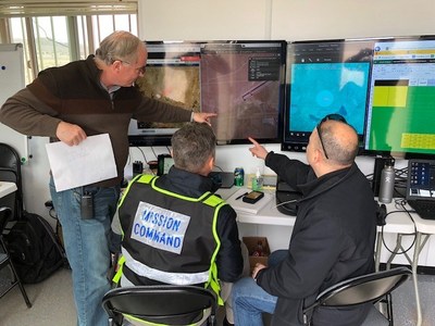
IRIS UAS program director Paige Cutland uses the IRIS UAS airspace situational awareness application to monitor the progress of a drone on a beyond line-of-sight (BVLOS) mission from a portable ground control station set up in a trailer.
Kongsberg Geospatial has been providing software design assurance to meet the certification requirements for real-time geospatial and spatial awareness technology to support air traffic management, air defense applications and unmanned systems for nearly three decades.
Their IRIS UAS situational awareness application had its genesis in supporting military UAV flight operations and was developed to help operators safely pilot UAVs in BVLOS operations. It was also used by regional airspace UTM managers to monitor the operations of multiple drones simultaneously.
The DO-278A standard (Guidelines for Communication, Navigation, Surveillance and Air Traffic Management [CNS/ATM] Systems Software Integrity Assurance) is the primary standard used by certification authorities such as FAA, EASA and Transport Canada to provide the assurance of software contained in non-airborne CNS/ATM systems. Unmanned systems manufacturers that build ground control stations for commercial drone systems, and airports and port authorities that create airspace control systems are anticipated to have to meet this standard when designing and building new systems.
By developing an airspace awareness application that satisfies this standard, Kongsberg Geospatial has provided a key component for unmanned systems manufacturers, airport operators and port authorities that wish to develop ground-based monitoring systems that are safe and certifiable for commercial operations.
“Unmanned Traffic Management and safe airspace operations will require certification of technology,” said Ranald McGillis, president of Kongsberg Geospatial. “We believe providing a certifiable airspace application will dramatically increase the safety of unmanned flight operations wherever it’s in use.”
NASA’s UAS Traffic Management System was tested May 25 at the Nevada UAS Test Site. (Credit: Drone America)
On May 25, the Federal Aviation Administration (FAA)-designated Nevada UAS Test Site and its NASA partners flew five different unmanned aerial vehicles (UAVs) to test NASA’s Unmanned Aircraft System Traffic Management (UTM).
The flights demonstrated multiple operational scenarios, including parachute-initiated emergency supply deliveries and aerial survey operations.
The UAVs were flown beyond the pilot’s visual line of sight using strategically placed visual observers and sophisticated command and control, communication and detect-and-avoid technologies.
The test is part of a three-week national campaign, which NASA is leading in close collaboration with the FAA and industry partners on a more complex version of its UTM technologies at six different UAS Test Sites around the nation.
The Technology Capability Level 2 (TCL2) National Campaign began May 9 with the Nevada UAS Test Site as the first of six UAS Test Site to begin UTM operations this year.
The partners not only demonstrated drone flight capability, but also tested UAS traffic mapping, sensor and radar technology, all of which were connected through a NASA UAS service supplier network to NASA Ames Research Laboratory.
Six FAA UAS Test sites and industry partners integrate their technologies with NASA’s UTM research platform and test the UTM concept in a range of conditions representative of those in the U.S. Airspace, explaind Tom Prevot, UTM project manager.
“For the Nevada NASA Team, we flew the longest multi-faceted NASA UTM flights to date in Nevada,” Prevot said. “The beyond-line-of-sight missions we completed over a distance of 13 miles north of Reno, Nevada, and the multiple aerial parachute package-delivery missions performed were a first in the National Airspace System under the NASA UTM.”
Current testing of the UTM TCL2 Test marks the second year in a row NASA has taken its UTM technologies on the road to further assess and refine their capabilities. During April 2016, NASA and its partners tested TCL1, which involved line-of-sight operations, and then began the first phase of TCL2 demonstrations in October 2016.
Two more phases, TCL3 and TCL4, each progressively more complex and involving flying drones with specific tasks over increasingly populated areas, are scheduled for 2018 and beyond.
The aerial parachute package-delivery missions performed were a first in the National Airspace System under the NASA UTM. (Credit: Drone America)
“Our Nevada NASA partners did an amazing job in extending the body of airspace management and sense-and-avoid knowledge under the UTM and across the UAS Industry,” said Chris Walach, director of the Nevada UAS Test Site. “The National Campaign data provided to NASA from our two-week operation will go a long way toward advancing the UTM for the FAA and the UAS Industry.”
“At AirMap, we consider UTM to be a critical ingredient for a thriving drone ecosystem,” said Steve Willer, business development manager for AirMap. “The TCL 2 trials demonstrate that technologies for geofencing, data exchange, and more can enable safe and sophisticated drone operations, even beyond line of sight. Along with NASA, the FAA, and NIAS we’re excited to show how UTM can chart a safe course for the drone ecosystem.”
“Drone America is a proud participant in a Nevada Institute for Autonomous Systems (NIAS) led NASA Unmanned Traffic Management (UTM) program at the Reno Stead Airport,” said Mike Richards, president and CEO of Drone America. “The safe integration of Unmanned Aerial Systems (UAS) into the National Airspace System (NAS) is critical to the future of this industry. Drone America is fortunate to call Nevada our home. Working in a state that is very supportive and business friendly makes a tremendous difference to our future sustainability. Our partnership with NIAS and NASA will not only contribute to successful testing, this partnership will pave the way for future generations to experience the true value of autonomous systems.”
“Carbon Autonomous Systems of Reno, in conjunction with their partner SmartPlanes of Skellefteå, Sweden, successfully took part in the planning, coordination, and flying in the most recent TCL2 NASA / NIAS UAS/UTM exercises conducted at the Reno Stead Airport UAS Test Range of the Nevada FAA UAS statewide test complex,” said John Hammond, chief pilot for Carbon Autonomous.
NIAS was also supported by Delair-Tech and SensoFusion who provided UAS and drone detection UAS technologies, which were also tested during this NASA UTM TCL 2 Test.
“We have been designing, manufacturing, and operating UAVs in the civilian airspace for almost 10 years in 100 countries,” said Benjamin Benharrosh, co-founder and head of Delair Tech North America. “This landmark agreement with NIAS, and the associated data collected for the UTM system designed by NASA at the Reno UAS Test Site will push our traffic management technology to a new level of precision and insight. We are thrilled to collaborate with NIAS on solutions that represent a new era for the commercial UAV market and a better presence of Delair-Tech in the U.S.”
“We’re excited to be shaping the future of air traffic management as an official partner of the NIAS by providing our counter-UAS solution, AIRFENCE, in the ongoing NASA UTM project. AIRFENCE is playing an active role in detecting, locating, and tracking UAS as part of the project, providing rich data to NASA as they develop their UTM system,” said Kaveh H. Mahdavi, Sensofusion VP of operations.
“NASA is one of Nevada’s most valuable partners. We appreciate the opportunity to support NASA’s UTM development. It is truly cutting-edge technology and will be instrumental in integrating UAS into the national airspace,” said Tom Wilczek, Aerospace & Defense Industry Representative for the Nevada Governor’s Office of Economic Development.
The Association for Unmanned Vehicle Systems International (AUVSI) Xponential 2017 show, May 8-11 in Dallas, convened a global community of commercial and defense suppliers in intelligent robotics, drones and unmanned systems. It showcases the broad forefront of autonomous vehicles generally, but in-flight in particular, and there were plenty of expanded capabilities and expanding applications on display.
In one of several keynotes over the course of the four-day show, Intel Corporation CEO Brian Krzanich predicted that in the oncoming era of driverless cars and autonomous aircraft, the most important aspect of such vehicles will be the data they collect rather than their performance. Big data and cloud processing are somehow tied into UAVs in his vision of things. Sometime soon, he forecast, autonomous devies “will have the ability to make decisions.”
Swarming drones have military potential, according to a 33-year career Marine who now works at the Potomac Institute for Policy Studies. Bill Powers described how a Navy program, the Low-Cost UAV Swarming Technology (LOCUST) uses drones to jam enemy communications and waste its resources by drawing fire. The Naval Research Laboratory dploys Close-in Covert Autonomous Disposable Aircraft (CICADA), with onboard sensors that relay atmospheric conditions as well as possition, time and altitude relating to battlefield conditions.
Watching the Watchers
With all the drones in the air, managing them and keeping the commercial airspace safe and uncluttered has become a towering problem. Several companies at AUVSI introduced unmanned traffic management (UTM) systems.
Unmanned traffic management becoming a priority (image courtesy Gryphon Systems).
Among them, Gryphon Sensors introduced Mobile Skylight, an operational mobile UTM system designed for rapid deployment.
Drone security applications span, according to the company, airport security, critical infrastructure protection, VIP security, embassy protection and border security. In the beyond visual line-of-sight (BVLOS) realm, UTM applications to be enabled by Mobile Skylight include: first responders (EMS, fire and police), precision agriculture, delivery, utility and infrastructure inspection, media and entertainment, mapping and surveying, construction and mining.
In short, everywhere drones go, they will need to be tracked and managed.
Mobile Skylight combines multiple technologies and an array of self-contained sensors, to serve as a mobile command center. The system is provided in a four-wheel drive van with off-road capabilities. It also integrates with third-party sensor inputs, and automatically records essential data for post-mission analysis and playback.
Using a dual-band mesh network, Mobile Skylight is capable of forward deploying a multispectral suite of sensors. Its integrated radar has been designed for 3-D detection of low-flying, small UAS and general aviation at ranges out to 10 kilometers and 27 kilometers, respectively. The system has built-in target tracking and classification to help quickly identify cooperative and non-cooperative targets. It also tracks multiple, simultaneous targets, providing a comprehensive picture of the airspace.
One novel application is heavy-lift drones for the construction and perhaps open-pit mining, quarrying and other weighty sectors. Griff Aviation, a Norwegian company that has set up a manufacturing plant in Florida, displayed its Super Heavy-Lift model, the Griff 300.
Super Heavy-Lift Drone from Griff Aviation image courtesy Gryphon Systems
The GRIFF 300 is an unmanned aircraft with customizable payload options that make it suitable for a variety of professional applications. The company states that it can lift 225kg (496lbs) in addition to its own 75kg (165lbs) weight. It features a flight time of 30-45mins, depending on payload. “The next model that will be produced will be able to lift 800kg (1,764lbs). Then we will continue to increase lifting capacity even further,” said CEO Leif Johan Holand.
Skylift Global drone prepping for flight. image courtesy Gryphon Systems
Several aisles over on the show floor, Skylift Global also featured a drone in the heavy lifting class. “Current prototype is 100 pounds and carried an additional 100 pounds easy. Currently undergoing testing for up to 400 pounds,” says its CEO Amir Emadi.
Skylift has signed agreements with companies in southern California to start deliveries of cold-chain logistics. Its heavy-lift capability can carry the added weight of refrigeration (think Amazon Fresh, says Emadi). Skylift also is in collaboration with JPL and Caltech to showcase a platform to DARPA for autonomous sense and avoid.
Neither company has GPS aboard their workhorses yet but see no problem and plenty of opportunity in adding it as their business develops.
Experienced GNSS Companies
NovAtel had on display its range of high-precision GNSS receivers, antennas, and augmented systems for ground, marine and airborne unmanned applications. Its equipment meets requirements for military and commercial applications, and specific to UAV applications the company offered the OEM625S SAASM GPS+civil RTK receiver, GAJT anti-jam antennas, TerraStar PPP correction services and SPAN GNSS+INS for 3D position, attitude and velocity.
The latter will be featured in the cover story of GPS World’s June issue, differentiating performance of various grades of IMUs in a tightly-coupled inertial/GNSS integration. Exploring IMU specifications and correlating them to performance of a final product can be daunting, as differences between MEMS sensors are not always apparent. The article will present achievable performances in fusion technology across a range of IMUs among the best in their respective performance categories.
Spirent Communications took a dual approach, displaying what they termed an entry-level simulator (although fully upgradeable as needs develop) for UAV manufacturers who are new to GPS signal testing, and even the need for it. They also had on hand their fully configured GSS7000 for multi-frequency testing, also with a modular approach to enable the precision GNSS simulation system to expand with users’ needs.
The GSS7000 series offers emulation of all civil GNSS systems and regional augmentation systems, and allows devices to be tested under a multitude of operating environments and error conditions, the company said. The GSS7000 has the flexibility to reconfigure satellite constellations, channels and frequencies between test runs or test cases. Four software control variants are offered.
The Association for Unmanned Vehicle Systems International (AUVSI) has renamed its major annual conference — XPONENTIAL — and the 2016 edition will be held in New Orleans at the Morial Convention Center on the west bank of the Mississippi, May 2–5. The huge convention center is hosting the event across two large halls, with more than 350,000 square feet of space for up to 600 exhibits.
With 370 exhibitors already signed up, you might want to decide who to put on your visit list if you’ve never been to one of these AUVSI exhibitions. Because just roaming the show floor without a plan can lead to frustration and exhaustion — the show is huge, not only in square feet, but also in the number and size of the exhibits. Full-size helicopters, Humvee-type vehicles and drones — lots and lots of different types of unmanned air vehicles (UAVs) or drones for any and all applications.
There is everything a drone manufacturer might need to develop and integrate into the latest small (sUAV), medium or large quadcopter, hexcopter, octocopter, fixed wing or STOL (short take-off and landing) air vehicle. Plus, you’ll find ground vehicles and surface and underwater vehicles of all shapes and sizes.
Propellers, engines, payloads of all sorts including cameras, radars, IR and lasers, plus connectors and electrical, mechanical and electro-mechanical components and systems, manufacturing systems, 3D printing, modeling, designing, developing — all in all, too much stuff to even mention everything that goes into, onto and processes/tools for manufacturing a UAV.
But, of course, our interest might be more readily captured by the booths exhibiting flight-control systems, sensors, antennas, autopilots, inertial, satellite and terrestrial radios and services, computing, GNSS and other guidance systems — and even avionics for drones. UAV ground control systems (UAV + ground control system = unmanned air system or UAS) are also present in force, along with all their constituent pieces. A ground control system can be more complex than a larger UAV, or sometimes as simple as an app on a tablet.
Applications are also featured in exhibit groupings for survey and mapping, air and start-up. Also, a large number of U.S. states and related academic, research, test and development organizations are represented this year, along with dedicated Chinese, French, Canadian and UK exhibit areas.
There also seems to be some presence for insurance, legal, certification and training organizations aiming to support the emerging commercial opportunities that Federal Aviation Administration (FAA) Section 333 approvals have enabled. The FAA continues to grant Section 333 exemptions, which have allowed commercial, research and agency drones to fly in the U.S. National Airspace System (NAS) on a trial and operational basis.
The FAA issued a fact sheet in mid-December that outlined safety reasons for federal oversight of aviation and airspace, and explained federal responsibility in this area. The object appears to be to let states know that the FAA has federal jurisdiction, and is therefore in charge of regulating access to and operations in the U.S. NAS. The fact sheet perhaps also aims to slow down recent state and city efforts — such as those in Miami, Albany County and New Jersey — to publish their own ordinances and laws related to UAV activity.
Meanwhile, the FAA’s recent UAV registration requirements for anything unmanned that takes to the air in the U.S. have met with mixed reactions. U.S. drone operators have indeed already complied and registered more than 181,000 UAVs, but one individual has filed a suit against the FAA alleging Section 333 does not allow the FAA to make any new rules or regulations regarding model aircraft if they’re flown for hobby or recreational purposes. We’ll have to see how this all turns out — AUVSI, which represents a good portion of the UAS industry, has already come out supporting the FAA’s UAV registration program.
AUVSI continues to call for the FAA to publish regulations that would allow small UAVs to operate in the U.S. NAS. These small UAV regulations have been in the works for several years and have yet to be formally released or implemented by the FAA. AUVSI argues that if these regulations were to be released, the commercial UAV industry would really take off and produce billions in revenue and create thousands of jobs.
In order to help move UAV integration forward, NASA has been working on traffic management concepts for UAS. The first section of this system was tested in August, looking mostly at topics such as geofencing so drones automatically avoid certain restricted areas, and also trajectory planning.
Google and Amazon have also been looking into UAS Traffic Management (UTM) systems. Amazon has proposed a high-speed UAS transit corridor between 200 and 400 feet, with slower vehicles flying below, and larger ones above it. Verizon has also been exploring how cellular networks could be used to enhance drone safety in the future. The FAA’s Pathfinder Programs also aim to investigate areas, such as beyond-visual-line-of-sight flights, that may assist in the development of UTM.
So, XPONENTIAL 2016 is a great UAV show to put in your calendar (May 2-5 in New Orleans) if you have interest in learning more about UAV/UAS, or in moving further into the growing business of UAVs, plus lots of related activity promising growth for actual UAV commercial operations in the U.S. There is always a lot going on nowadays in the world of unmanned vehicles.