Blog

  • NGS will soon compute third multi-year CORS solution

    NGS will soon compute third multi-year CORS solution

    On Aug. 5, the National Geodetic Survey (NGS) stated it will be updating the NOAA CORS to be aligned with the latest International Terrestrial Reference frame, ITRF2020 (see below). As stated in the announcement, NGS will soon compute a third multi-year continuously operating reference station (CORS) solution, MYCS3.

    The last multi-year CORS solution, MYCS2, was performed by NGS in 2019. I discussed the MYCS2 in my February 2019 and April 2019 columns. This new multi-year CORS solution will be important to the 2022 modernized National Spatial Reference System (NSRS), because NGS will establish a strict mathematical relationship between the 2022 NSRS frames and the ITRF2020 frame. This will allow direct access to the NSRS (NOAA Technical Report NOS NGS 67).

    NGS Aligns National System to Global Reference Frame

    August 5, 2022

    The International Global Navigation Satellite System (GNSS) Service, which provides GNSS data products globally, recently released a new GNSS-only version of the International Terrestrial Reference Frame. This provides GNSS users access to the reference frame through coordinate functions for a global set of reference stations. In response, NGS will soon compute the multi-year Continuously Operating Reference Station (CORS) Solution 3, which will modernize the National Spatial Reference System. Aligning the National Spatial Reference System with the updated global reference frame will allow greater access for the global community of scientists, educators, and commercial users of location science.

    For more information, contact: Phillip McFarland

    As in the past, the multi-year CORS solution will mean that the NOAA CORS coordinates will be updated to be consistent with the latest International Terrestrial Reference Frame of 2020 (ITRF2020). The International GNSS Service provides information about its GNSS products and services. Readers can find information on the latest International Terrestrial Reference Frame 2020 here. This column will provide basic information on the ITRF2020. Please note: NGS stated that it will soon start computing the third multi-year CORS solution, but — as of October — all NOAA CORS coordinates are still based on MYCS2 and provide coordinates in ITRF2014 epoch 2010.00 and NAD 83 (2011, MA11, PA11) epoch 2010.00. As in the past, NGS will provide advance notice before publishing the results of its third multi-year CORS solution.

    A document on the ITRF website stated the ITRF2020 is expected to be an improved solution compared to the previous solution, ITRF2014. It listed several innovations introduced in the ITRF2020 processing.

    Description from ITRF2020 Document

    ITRF2020 is the new realization of the International Terrestrial Reference System. Following the procedure already used for previous ITRF solutions, the ITRF2020 uses as input data time series of station positions and Earth Orientation Parameters (EOPs) provided by the Technique Centers of the four space geodetic techniques (VLBI, SLR, GNSS and DORIS), as well as local ties at colocation sites. Based on completely reprocessed solutions of the four techniques, the ITRF2020 is expected to be an improved solution compared to ITF2014. A number of innovations were introduced in the ITRF2020 processing, including:

    • The time series of the four techniques were stacked all together, adding local ties and equating station velocities and seasonal signals at colocation sites;
    • Annual and semi-annual terms were estimated for stations of the 4 techniques with sufficient time spans;
    • Post-Seismic Deformation (PSD) models for stations subject to major earthquakes were determined by fitting GNSS/IGS data. The PSD models were then applied to the 3 other technique time series at earthquake colocation sites.

    The box below provides a good summary of the International Reference Frame and why it’s important to the scientific community as well as the surveying and mapping community. Readers can download the article from the June 2022 International GNSS Service Issue 4 newsletter. Users also can sign up to receive notices and newsletters from the International GNSS Service.

    ITRF2020: A new release of the International Terrestrial Reference Frame By Zuheir Altamimi

    What is the current rate of sea level rise in different regions of the globe? How does our Earth deform under the effect of plate tectonics, seismic phenomena, or the melting of ice caps? How the Earth’s center of mass is varying? How to determine the position of a point on the surface of a constantly deforming Earth and compare it to positions estimated decades apart? The answers to these fundamental questions for understanding the dynamics of our planet require the availability of a global, long-term stable terrestrial reference frame, but preferably a standard reference so to ensure interoperability and consistency of various measurements collected by sensors on the ground, or via artificial satellites. The International Terrestrial Reference Frame (ITRF) is the standard reference recommended by a number of international scientific organizations, including the International Union of Geodesy and Geophysics (IUGG) and the International Association of Geodesy (IAG) for earth science, satellite navigation and operational geodesy applications. The ITRF is an international effort that is built on the investments of space and mapping agencies, universities and research groups in operating geodetic observatories, archiving and analyzing the collected geodetic observations to derive not only the ITRF, but also critical geodetic products for science and society.

    The ITRF integrates and unifies technique-specific reference frames provided by the four IAG’s international services of space geodetic technique (DORIS/IDS, GNSS/IGS, SLR/ILRS, VLBI/ IVS). It is supplied to the users in the form of temporal coordinates of more than 1500 stations, Earth Orientation Parameters, as well as parametric functions describing nonlinear station motions: seasonal signals due to mainly loading effects and post-seismic deformations for sites subject to major earthquakes. It is necessary to regularly update the ITRF (approximately every 5 years) in order to benefit from continuous observations so to improve its accuracy, considering station position temporal variations due to geophysical phenomena.

    The ITRF is maintained by a research group at IGN-France and IPGP (Institut de Physique de Globe de Paris), and whose new release called ITRF2020 was published on April 15 and accessible here: https://itrf.ign.fr/en/solutions/ITRF2020. The ITRF2020 brings significant improvements compared to previous achievements: it confirms the estimate of the position of the center of mass of the Earth as it was determined in 2016, but also provides its seasonal variations; it improves the accuracy of the scale of the frame at the millimeter level, which represents a gain in precision of a factor of 8 on the measurement of the size of the Earth (compared to that determined in 2016); it provides a precise quantification of co- and post-seismic displacements caused by devastating earthquakes, such as that of Sumatra in 2004, Chile in 2010 and Japan in 2011. The IAG Services rely on the ITRF to align their geodetic products to it, and therefore disseminate it widely among the various users. In particular, using the IGS products, such as the orbits, allows a universal access in space and time to the ITRF.

    As stated in the article by Zuheir Altamimi, ITRF2020 involves IAG’s international services of four space geodetic techniques: DORIS/IDS, GNSS/IGS, SLR/ILRS, VLBI/ IVS. Computing an International Terrestrial Frame is very complex and requires analyses of difference types of geodetic and geophysical data. It is beyond the scope of this column, but online is more detailed technical information.

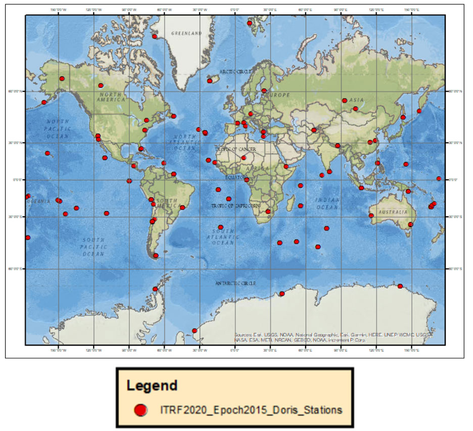
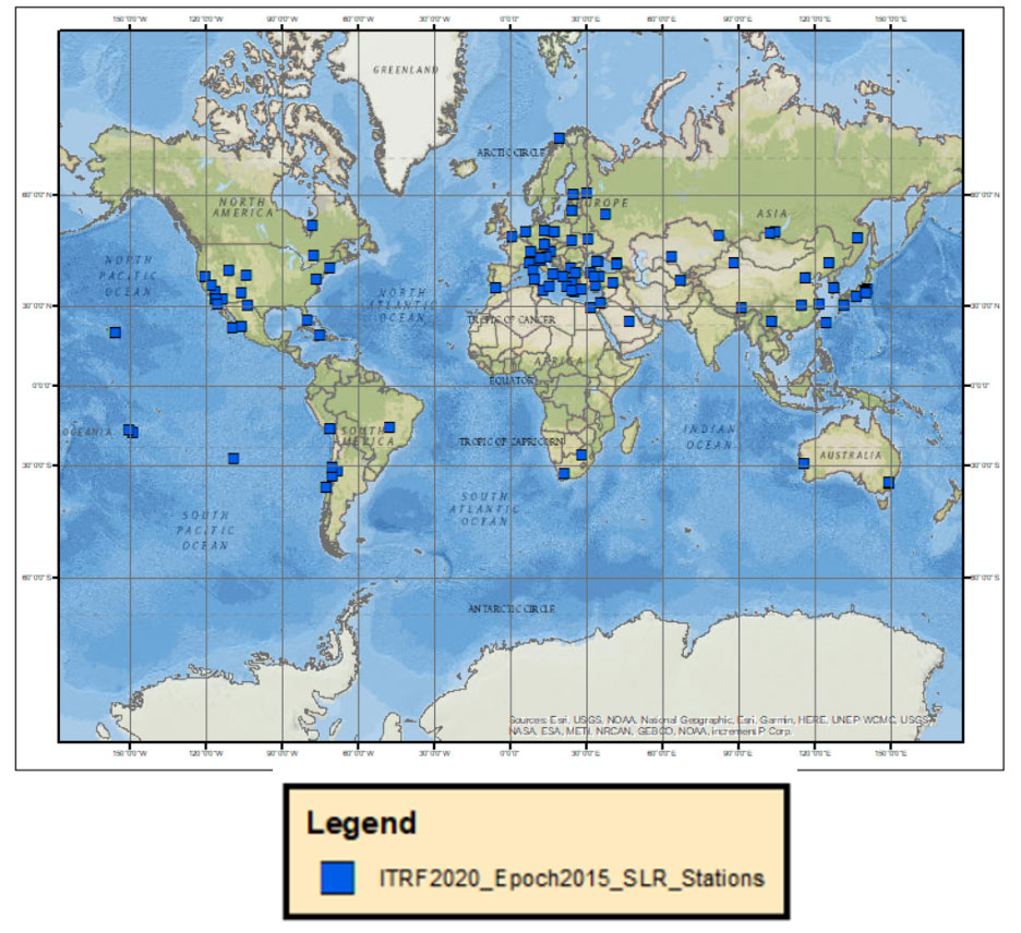
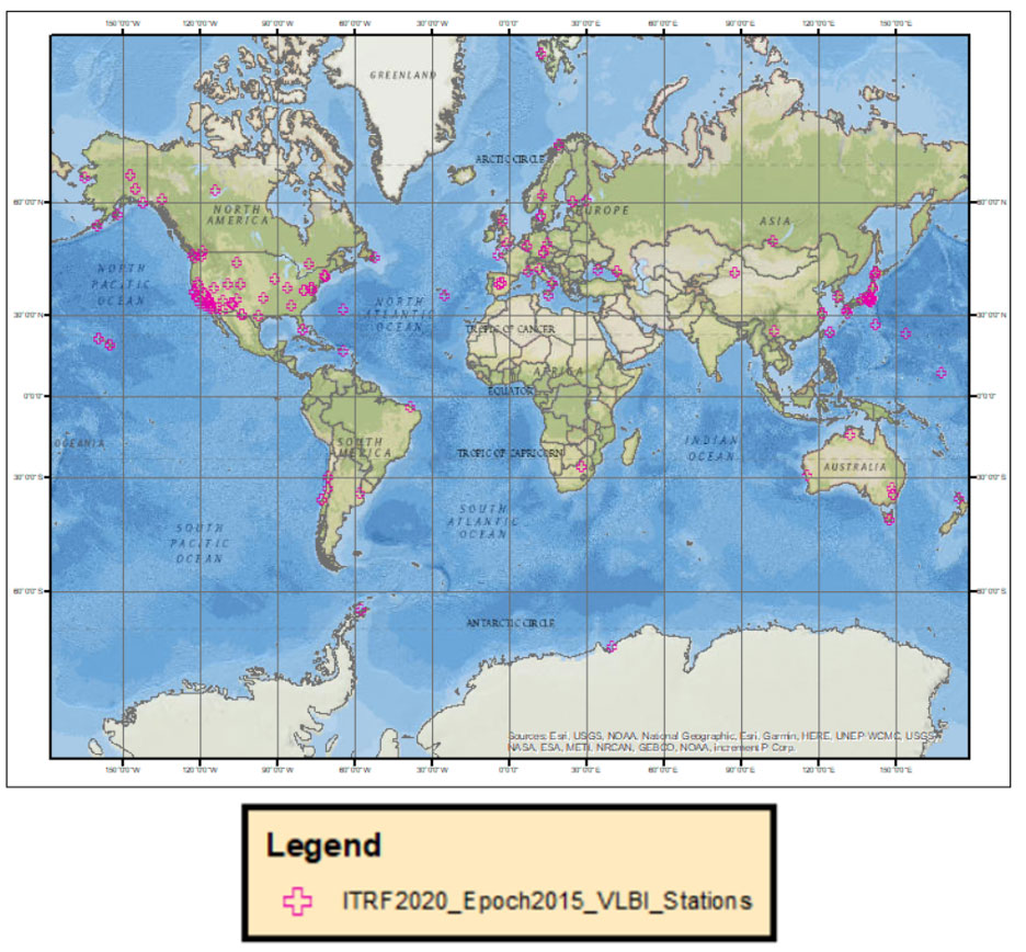
    For this column, I downloaded the station lists from the four space geodetic techniques and provided a few plots that depict the location and velocities of these sites. The box below depicts the location of the space geodetic techniques around the world. As indicated in the plot, some locations have more than one technique collocated at the same site.

    Plot of the Four Different Space Geodetic Techniques
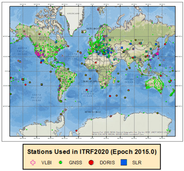
    Image: David Zilkoski
    Image: Dave Zilkoski

    The following plots depict the locations using each space geodetic techniques: GNSS sites, DORIS sites, SLR sites and VLBI sites.

    Plot of GNSS Sites
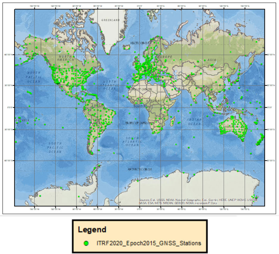
    Image: David Zilkoski
    Image: Dave Zilkoski


    Plot of DORIS Sites

    Image: David Zilkoski
    Image: Dave Zilkoski

    Plot of SLR Sites

    Image: Dave Zilkoski
    Image: Dave Zilkoski

    Plot of VLBI Sites

    Image: Dave Zilkoski
    Image: Dave Zilkoski

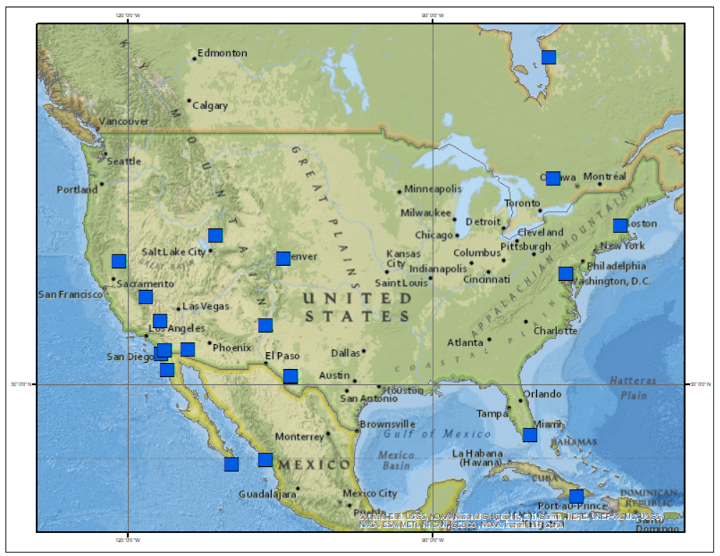
    The box below shows the location of the techniques in the conterminous United States.

    Plot of the Four Different Space Geodetic Techniques in the CONUS
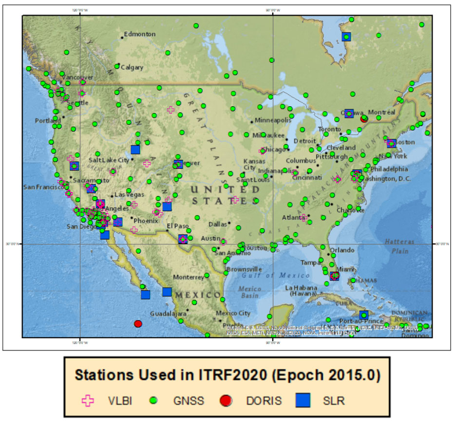
    Image: Dave Zilkoski
    Image: Dave Zilkoski

    The plot below depicts the sites in the state of Alaska.

    Plot of the Four Different Space Geodetic Techniques in the Alaska
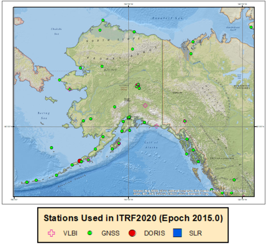
    Image: Dave Zilkoski
    Image: Dave Zilkoski

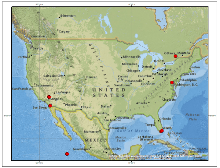
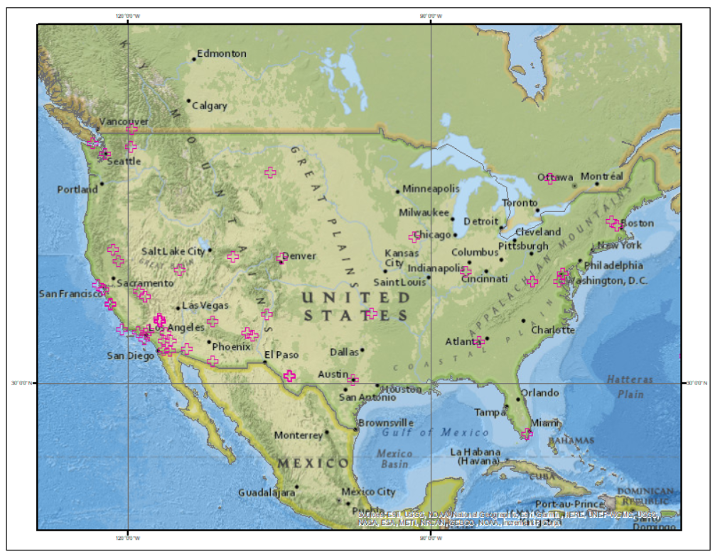
    The images below depict each of the four space geodetic techniques in the conterminous United States.

    Plots of the Space Geodetic Techniques by Technique in the CONUS
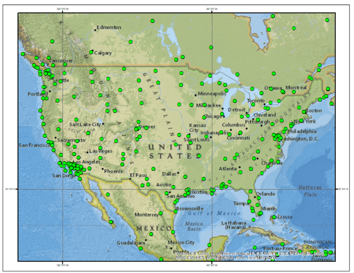
    Image: Dave Zilkoski
    Plot of GNSS Sites in CONUS Image: Dave Zilkoski
    Image: Dave Zilkoski
    Plot of DORIS Sites in CONUS (Image: Dave Zilkoski)
    Image: Dave Zilkoski
    Plot of SLR Sites in CONUS (Image: Dave Zilkoski)
    Image: Dave Zilkoski
    Plot of VLBI Sites in CONUS (Image: Dave Zilkoski)

    Altamimi’s article on the ITRF2020 stated it is “necessary to regularly update the ITRF (approximately every 5 years) to account for station position temporal variations due to geophysical phenomena.” My February 2022 column discussed the tectonic plates and why is it necessary to account for movement in a geodetic reference frame. As I stated then, coordinates basically change because the Earth’s surface is moving due to the movement of major tectonic plates. See the box titled “What is Tectonic Shift?” for information about why it is called plate movement or tectonic shift. The world’s geodesists understand this and are attempting to manage the changing coordinates by providing a time-dependent component of the international terrestrial reference frame.
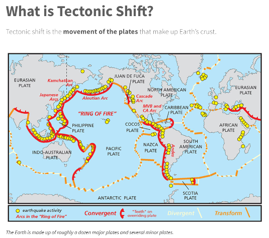

    Image: National Ocean Service Website
    Image: National Ocean Service website
    Image: National Ocean Service Website
    Image: National Ocean Service website

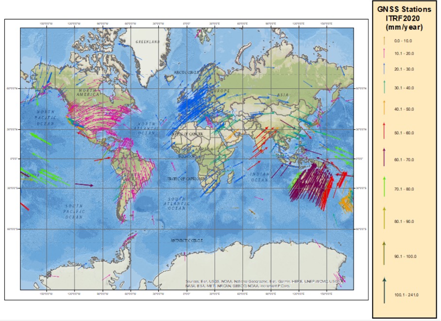
    The box below depicts the horizontal velocity based on the ITRF2020 velocities (downloaded on 08/12/2022).

    Plot of the Horizontal Velocity Vectors based on the ITRF2020 Velocities
    (Image: Dave Zilkoski)
    Image: Dave Zilkoski

    The box below depicts the horizontal velocities in the North America. These vectors look very similar to the velocities reported in my February 2022 column.

    Plot of the Horizontal Velocity Vectors in North America based on the ITRF2020 Velocities
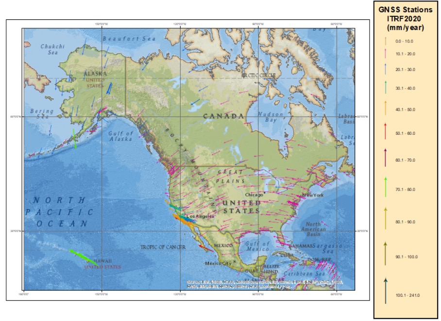
    Image: Dave Zilkoski
    Image: Dave Zilkoski

    For a comparison to North America vectors, the box below depicts the velocity vectors in Europe.

    Plot of the Horizontal Velocity Vectors in Europe based on the ITRF2020 Velocities
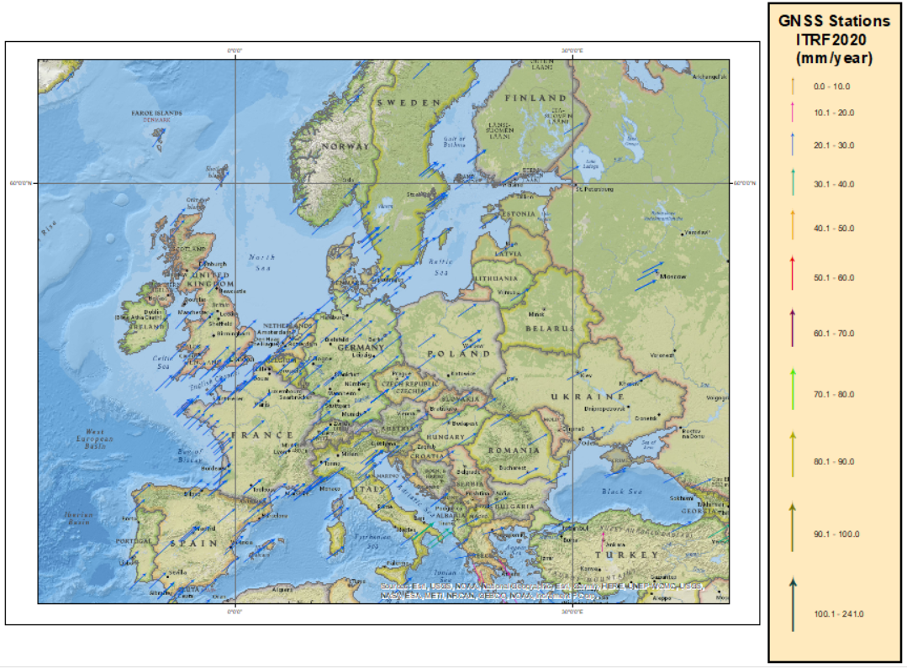
    Image: Dave Zilkoski
    Image: Dave Zilkoski

    They are similar in magnitude, but not in direction. Once again, looking at the map of tectonic plates, North America is located mostly on the North American plate and Europe is on the Eurasian plate.

    Australia is on the Indo-Australian plate and has some fairly large horizontal velocities vectors. See the box below.

    Plot of the Horizontal Velocity Vectors in Australia based on the ITRF2020 Velocities
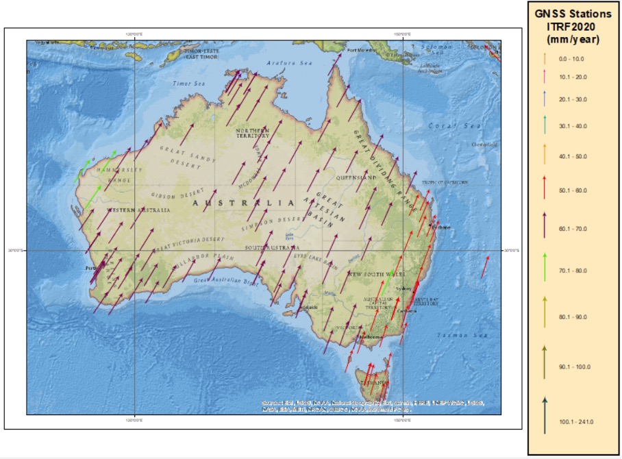
    Image: Dave Zilkoski
    Image: Dave Zilkoski

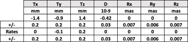
    So, what’s the difference between ITRF2014 and the new ITRF2020? The box below provides the 14 transformation parameters from ITRF2020 to ITRF2014. These transformation parameters have been estimated using 131 stations located at 105 sites. See the box “Plot of the Stations used in the Transformation Parameters from ITRF2020 to ITRF2014” for the location of these stations. Notice that the translation values in X,Y,Z are very small (<1.5 mm) between the two reference frames.

    Transformation Parameters from ITRF2020 to ITRF2014
    (https://itrf.ign.fr/en/solutions/ITRF2020)
    (https://itrf.ign.fr/en/solutions/ITRF2020)

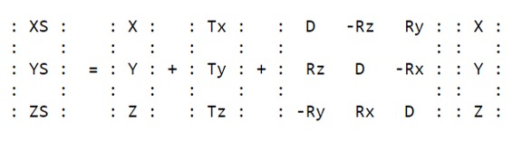
    Transformation parameters at epoch 2015.0 and their rates from ITRF2020 to ITRF2014 (ITRF2014 minus ITRF2020)
    (https://itrf.ign.fr/en/solutions/ITRF2020)
    (https://itrf.ign.fr/docs/solutions/itrf2020/Transfo-ITRF2020_TRFs.txt)

    X,Y,Z are the coordinates in ITRF2020, and XS,YS,ZS are the coordinates in ITRF2014.

    Plot of the Stations used in the Transformation Parameters from ITRF2020 to ITRF2014
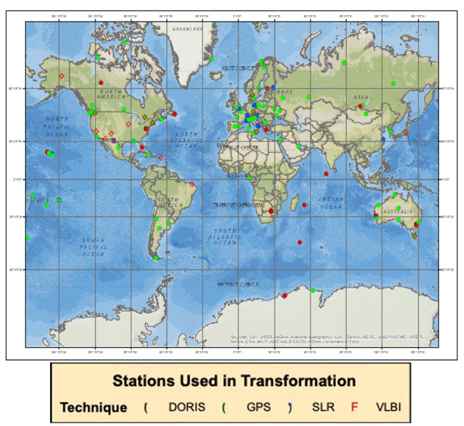
    Image: Dave Zilkoski
    Image: Dave Zilkoski

    The transformation parameters from ITRF2020 and past ITRFs are provided in the table below. As indicated in the table, most of the changes in X,Y and Z are very small since ITRF2005.

    Transformation Parameters from ITRF2020 to Past ITRFs
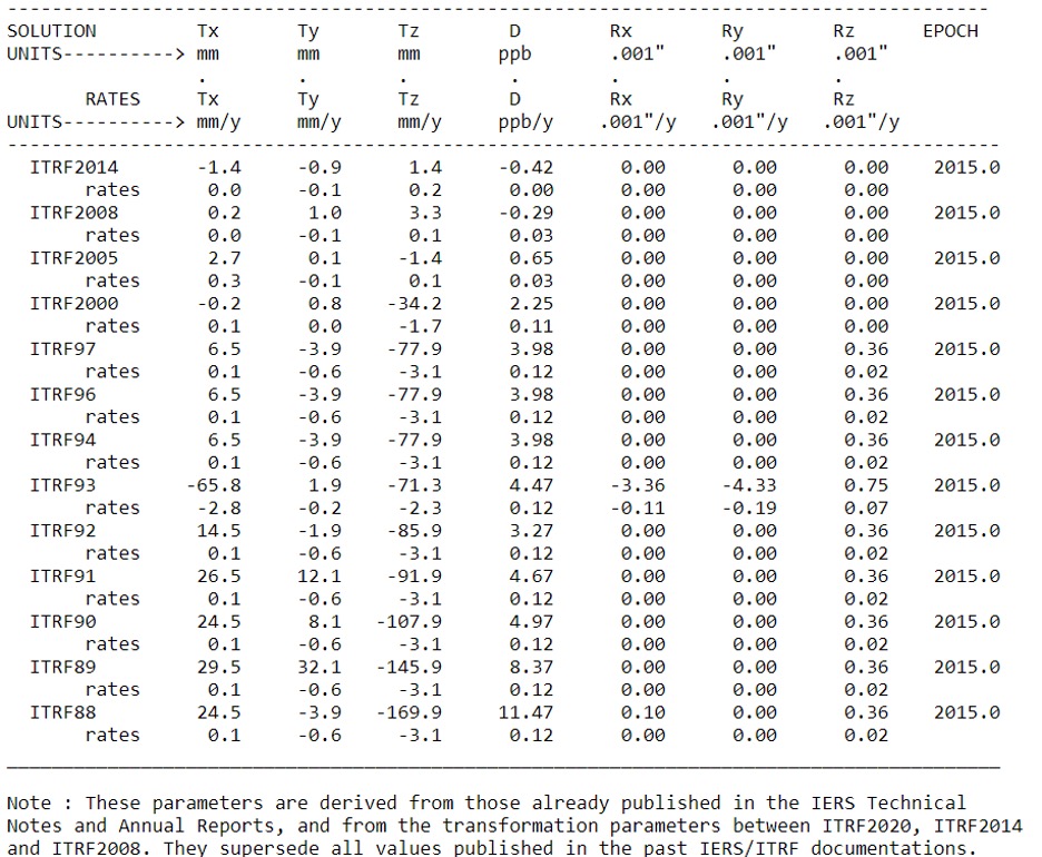
    (https://itrf.ign.fr/docs/solutions/itrf2020/Transfo-ITRF2020_TRFs.txt )
    (https://itrf.ign.fr/docs/solutions/itrf2020/Transfo-ITRF2020_TRFs.txt)

    As previously stated, the third multi-year CORS solution will be important to the new 2022 modernized National Spatial Reference System (NSRS) because NGS will establish a strict mathematical relationship between the 2022 NSRS frames and the ITRF2020 frame. This will allow direct access to the NSRS, according to NOAA Technical Report NOS NGS 67. Again, there will not be any changes to NGS’s NOAA CORS coordinates due to ITRF2020 until NGS completes its third multi-year CORS solution.

    Users can receive emails about the latest NGS News by signing up for NGS’s newsletters. These notices will highlight the release of new products, updates to existing services, progress reports for major projects, information about upcoming NGS-sponsored events, and job opportunities at NGS.


  • Averna partners with PI Group for manufacturing

    Averna partners with PI Group for manufacturing

    Averna logoAverna and Physik Instrumente (PI) have formed a new partnership to deliver advanced automation solutions that meet the growing need for flexible, scalable and high-throughput manufacturing and test equipment.

    Physik Instrumente (PI) is an international group of companies focusing on high-precision motion and positioning solutions, and Averna is a global test and quality solutions provider.

    With significant overlap in several markets — industrial automation, automotive, consumer electronics, communications and life sciences — PI and Averna each offer expertise in different areas. Their goal is to expand each offering to their clients by integrating PI’s unique precision positioning and micro-robotics systems into Averna’s customized quality and assembly turnkey solutions.

    To date, the two companies have delivered numerous joint projects, improving results for a variety of applications including camera and projector assembly, laser alignment, fiber alignment and optical wafer scanning.

    “We are very excited to begin this partnership,” said Niels Davidts, vice president of Europe at Averna. “Having worked with PI products in the past, we understand the power of what they offer. They are unique in what they do, and we know how to make them work best for our clients. A closer partnership will open a lot of opportunities for both parties.”

    Scott Jordan, long-standing photonics expert and business developer at PI emphasizes, “Working with Averna has been very rewarding. We have always been impressed with the systems they design for test, quality, and precision assembly. Combining our knowledge with Averna’s skills, we can now approach customer challenges in ways that have never been done before.”

  • John Deere opens RFP for satellite communications solution

    John Deere opens RFP for satellite communications solution

    John Deere logo

    Deere & Company has issued a request for proposals (RFP) to secure a satellite communications solution that will further connect its fleet of intelligent machines. The solution will enhance the satellite connectivity that Deere is delivering to its customers.

    “We believe satcon will unlock significant opportunities in agriculture by enabling farmers to take advantage of innovative technologies that rely on real-time information and communication,” said Lane Arthur, vice president of Data, Applications and Analytics at John Deere. “For example, autonomous tractors benefit from real-time communication through the John Deere Operations Center, as farmers use the app to start and stop the machine, monitor the job it’s executing, and determine what it should do when it encounters an obstacle.”

    During the initial phase, Deere is seeking a strategic partnership with a vendor or set of vendors to connect both new machines and retrofitted machines through satellite service and ruggedized satellite terminals. This is expected to enable Deere’s customers to be more productive and efficient, and increase food and fuel production.

    For more information on the request for proposals, contact [email protected].

  • ESA seeks companies to help guide Moon missions

    ESA seeks companies to help guide Moon missions

    The European Space Agency (ESA) is looking for companies interested in helping create a constellation of lunar satellites to connect and guide missions to the Moon. Creating lasting telecommunications and navigation links with the Moon will enable sustainable space exploration for the hundreds of lunar missions that are due to launch within the next few decades, ESA stated.

    The companies would provide telecommunications and navigation services to these lunar missions, under its Moonlight initiative.

    ESA is completing two studies with two consortia of space companies based in Europe that assess the business case and the technical solutions for building and operating a constellation of lunar satellites. ESA is asking any space firms to indicate whether they would like to become involved in the ambitious project — or simply to develop lunar telecommunication and navigation technologies and products. The deadline is Oct. 28.

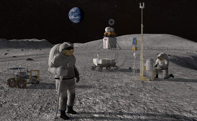
    Artist’s rendering: NASA
    Artist’s rendering: NASA

    On Sept. 19, ESA Director General Josef Aschbacher and NASA Administrator Bill Nelson signed a joint statement on lunar exploration cooperation at the International Astronautical Congress in Paris.

    The lunar Gateway  will be an outpost in orbit around the Moon. It will serve as the staging point for both robotic and crewed exploration of the lunar south pole.

    ESA’s European Service Modules will power all Artemis Orion spacecraft to the Moon and back. ESA will also provide refueling elements for Gateway and a communications module that will pave the way for Moonlight.

    ESA has already initiated the Lunar Pathfinder project to provide initial communications services to early lunar missions, which will also help to prepare for the next stage with Moonlight. The Lunar Pathfinder will also include a navigation payload demonstrator, which will allow positioning in lunar orbit using GPS and Galileo systems for the first time, and is due to launch in 2025.

    Space companies in Europe and Canada will be invited to tender for the initial Moonlight work in December.

  • Trimble’s new ag displays provide connectivity for in-field operations

    Trimble’s new ag displays provide connectivity for in-field operations

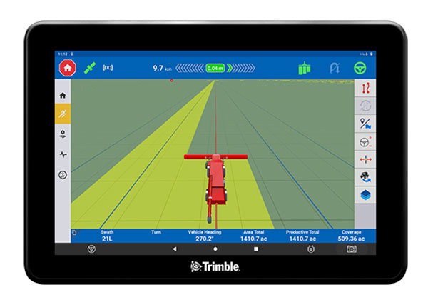
    The GFX-1260 display for precision agriculture. (Photo: Trimble)
    The GFX-1260 display for precision agriculture. (Photo: Trimble)

    Trimble has introduced next-generation displays for precision agriculture applications — the Trimble GFX-1060 and GFX-1260.

    The displays enable farmers to complete in-field operations quickly and efficiently while also mapping and monitoring field information in real time with precision, Trimble said. Both displays feature an Android-based operating system and enhanced processing power for controlling and executing in-field work.

    The new flagship GFX-1260 is a 12-inch (30.5 cm) display, while the GFX-1060 is a 10-inch (25.6 cm) display, and both are compatible with the Trimble NAV-500 and NAV-900 GNSS guidance controllers.

    When paired with the NAV-900, farmers can achieve increased accuracy out of the box by leveraging Trimble’s leading CenterPoint RTX correction service, which is included for the first year.

    The high-resolution touchscreen displays are compatible with more than 10,000 vehicle models across more than 40 equipment brands. The displays are ISOBUS-compatible, which allows one display or terminal to control ISOBUS implements, regardless of manufacturer. It standardizes control settings, reduces downtime and minimizes installation and interface challenges, simplifying data exchange and machine control.

    The new displays enable farmers to set up and configure their equipment through Trimble’s Precision-IQ field software, including manual guidance, assisted and automated steering, application controls, mapping and data logging, equipment profiles and camera feeds from attached inputs and other internet-based apps.

    Running the powerful Precision-IQ software, the Trimble GFX-1060 and GFX-1260 displays feature:

    • flexible connectivity across the farm through integrated wireless options including Bluetooth, Wi-Fi and BroadR-Reach high-speed communications
    • seamless communication from tractor to farm equipment through ISOBUS compatibility, the Field-IQ crop input control system, and Trimble Universal Variable Rate (TUVR) or serial rate control
    • ability to connect to GNSS correction services including Trimble RTX technology, CenterPoint RTK and CenterPoint VRS through the NAV-900 controller
    • compatibility with all Trimble guidance systems as well as CAN bus support for both assisted and automated steering
    • interoperability with Trimble Ag Software to support data management needs across the farming ecosystem
    • data sharing across the farm with the optional AutoSync feature, allowing farm managers to remotely send work orders and ensure vehicles, implements and fieldwork are aligned and working properly.
  • Finding your way with broadcast TV

    Finding your way with broadcast TV

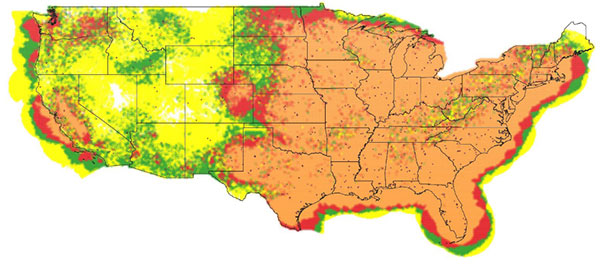
    CONUS full-power UHF TV stations in view: yellow (1—3 stations), green (4—6), red (7—10), orange (11 or more). (Image: NAB)
    Full-power UHF TV stations in view in the continental United States: yellow (1—3 stations), green (4—6), red (7—10), orange (11 or more). (Image: NAB)

    Over the years, we have seen several proposals to use television broadcasts for positioning, navigation, and timing (PNT). This idea was taken one step further in a paper by the staff of the National Association of Broadcasters (NAB). We talked with one of the authors, Robert Weller, NAB’s vice president for spectrum policy, to find out more.

    Goward. Bob, your paper calls the notional system the “Broadcast Positioning System” or “BPS.” What is new about your proposal? And what led you and your colleagues to develop this idea and publish the paper?

    Weller. Television broadcasters are transitioning to a new transmission standard, ATSC 3.0, that plays well with other industry protocols, has more robust operating points, stricter timing requirements, and is much more flexible. There are already more than 50 US markets with a station transmitting ATSC 3.0. Our paper began to analyze PNT in the context of ATSC 3.0 and confirmed that there was a good match. So, the idea of “broadcast positioning” was born.

    Goward. In general, how would BPS work?

    Weller. TV stations transmit from towers at known fixed locations. A TV station can transmit its precise location (geographic coordinates and antenna elevation) along with a time-stamp. For fixed receivers using the timing service, only one TV signal is required. Receivers would know their location a priori and would simply calculate their distance from the TV station and use that distance to determine the corresponding time that it takes for the signal to travel from the TV transmitting antenna. That time difference is then added to the received time-stamp to determine the present time at the receiver.

    Both fixed and mobile users could access positioning and timing services when at least three TV stations are within range.

    Goward. GPS and other GNSS are ubiquitous. What advantages do you see BPS having over space-based navigation systems?

    Weller. BPS is not intended to replace GPS. BPS can provide an independent timing and/or position determination, which can provide confidence and help detect spoofing or other problems with GPS. BPS also has the advantage of high power and strong signal levels. Most UHF television stations radiate 1 megawatt of power, which does a good job penetrating buildings and is difficult to jam or spoof.

    Goward. There have been many proposals for terrestrial systems to complement GPS. In general, what advantages would implementing BPS have over other non-space approaches?

    Weller. There are several advantages. The cost to deploy will be less since the broadcast infrastructure is already in place. Also, because of our high power, the number of nodes necessary is fairly small. I’ll add that TV stations are built to operate 24/7, so most of them are fairly “hard” with back-up power and redundant transmitters. Additionally, the modulation and coding we propose for BPS is intended to provide service well above the noise floor, making it quite robust. Finally, low-cost receivers that are used in televisions can be used to decode the BPS information.

    Goward. Your paper says that using the television stations we have today, geographically about 85% of the contiguous United States by land area would be able to get PNT services from BPS. The number is 99% for just timing services. Do you have any thoughts about those not in range for services?

    Weller. Those percentages were intended to be conservative and only considered full-power UHF TV stations. There are also hundreds of VHF stations and thousands of low-power TV stations. If you include those stations, the coverage percentages are even higher. It’s certainly possible to add more stations if needed to reach the most remote and unpopulated parts of the United States.

    Goward. What about user equipment? Have you done any work in that area? How small do you think receivers could be eventually?

    Weller. There are compact GPS and Loran receivers out there, and the technology for BPS isn’t much different. Some Korean companies have already built very small ATSC 3.0 receivers to carry RTK corrections to GPS for use in drones. There are also already ATSC 3.0 USB receivers that weigh less than an ounce.

    Goward. Are there other services that BPS could provide?

    Weller. BPS can be one element of a PNT system-of-systems that also improves other PNT services. In my opinion, the most valuable service BPS can provide is an alternative reference for critical infrastructure if GPS is compromised. However, BPS would occupy a tiny fraction of ATSC 3.0 signal capacity. So, there could be additional services such as transmitting ephemeris data for expedited GPS acquisition, RTK data for improved PNT accuracy, or even map information.

    Goward. Have you thought about what you would be using as a time source?

    Weller. Most TV stations already have GPS, but since the point of BPS is to provide redundancy and resilience to GPS, we’re looking at cesium clocks, optical fiber, and eLoran as possibilities.

    Goward. NAB is a trade association. How do you see this project benefiting your members?

    Weller. This project affirms the public service mission of broadcasters as well as our designation as critical infrastructure. If broadcasters are compensated for the equipment and resources required for deploying and operating BPS as a public service, I expect high participation and user adoption.

    Goward. Where do you think you and your colleagues will take the project from here?

    Weller. We’re working with possible users to determine their requirements while also trying to identify funding sources to enable the development. We hope to build prototypes and launch market trials as next steps towards commercialization.

  • GPSdome: Industry’s Most Disruptive GPS Anti-Jammer

    [SPONSORED CONTENT] GPS jamming has become the #1 threat to defense and commercial drones. Therefore we developed GPSdome: a GPS protection solution tailored for defending drones and vehicles from jamming attacks. GPSdome provides a robust cyber shield, allowing the protected platform to safely and continuously operate and complete missions in a GPS-challenged environment. At its minimal size weight and power, there is no other solution that offers such protection as small, light, affordable or as easily installed as GPSdome.

    Learn more.

    This video is sponsored content from Infinidome.

  • Navigation company iXBlue acquired by Groupe Gorgé

    Navigation company iXBlue acquired by Groupe Gorgé

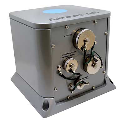
    Photo: ixBlue
    Photo: ixBlue

    Groupe Gorgé has acquired navigation company iXblue. The move will bring together iXblue and Groupe Gorgé subsidiary ECA Group.

    Groupe Gorgé is a European company specializing in high-tech industrial solutions for the robotics, maritime, navigation, aerospace and photonics markets. Together, iXblue and ECA Group will provide customers with components and complex systems to support critical missions in severe environments.

    The two companies will have a global workforce of 1,500 people and will achieve an annual turnover of €250 million.

    “In addition to our complementary activities, both our companies share a common DNA centered around innovation and entrepreneurship,” said Fabien Napolitano, president and CEO of iXblue. “This acquisition by Groupe Gorgé, which puts iXblue and ECA Group under the same roof, will enable us to create new synergies and strengthen our capacity to invest in research and development to offer solutions that are always at the cutting edge of technology.”

    Dominique Giannoni, CEO of ECA Group, added, “With the combination of the technological expertise and global footprint of the two companies, we will provide unmatched value to our customers through our comprehensive portfolio of products and solutions. This operation consolidates our leadership in our markets and offers excellent growth prospects. The teams of our two companies have already started working closely together. We see great development opportunities that we are eager to share with our customers.”

  • ION ITM/PTTI 2023 abstracts due October 7

    ION ITM/PTTI 2023 abstracts due October 7

    Logo: IONAbstracts for ION ITM/PTTI 2023 are due Friday, October 7.

    Submit your abstract for the Institute of Navigation’s (ION) combined International Technical Meeting (ITM) and the Precise Time and Time Interval (PTTI) Systems and Applications Meeting 2023. The co-located conferences will take place January 23-26 at the Hyatt Regency Long Beach, Long Beach, California. Both in-person and virtual presentation options will be available.

    The International Technical Meeting (ITM), is is the ION’s winter meeting, with technical papers related to positioning, navigation and timing and includes the ION Fellows and Annual Awards presentations.

    The Precise Time and Time Interval Systems and Applications (PTTI) meeting is an annual conference sponsored by ION with a technical program designed to disseminate and coordinate PTTI information at the user level, review present and future PTTI requirements, inform government and industry engineers, technicians, and managers of precise time and frequency technology and its problems, and provide an opportunity for an active exchange of new technology associated with PTTI.

  • Space Tech Expo Europe to showcase industry trends

    Space Tech Expo Europe to showcase industry trends

    Space Tech Expo Europe will make its return to Bremen, Germany November 15-17.  The full agenda has been released, detailing the speakers, sessions and pressing topics that will help to shape the future of a thriving space industry.

    Space Tech Expo Europe provides attendees with fundamental knowledge on current industry trends, challenges, and opportunities in unmissable discussions from technical-level experts from across the supply chain. The expo boasts over 100 speakers, over 450 exhibitors and three separate conferences over three days.

    Conferences

    The Industry Conference at Space Tech Expo Europe provides audiences with critical insights into the latest updates and key trends happening in the European (and beyond) space sector, aiming to help shape the future of our thriving industry.

    Sessions taking place at the Industry Conference will shed light on the sector’s most pressing matters, including industry developments, investment, space exploration, launch, digitalization, the in-space supply chain, space sustainability, and much more.

    The Smallsats Conference at Space Tech Expo Europe enables the small satellite community to meet and explore the most exciting developments in the market. Here, the upstream small satellite technology providers, downstream service providers and end-users come together to address the sector’s biggest trends. Topics will include launch and propulsion, increasing satellite manufacturing capabilities, standardization, exploring downstream applications of remote sensing data, creating actionable data insights, and space cyber security.

    The Mobility Connectivity Conference at Space Tech Expo Europe bridges the gap between merchant shipping, cruise shipping and commercial aviation’s connectivity requirements, and the technical solutions satellite operators, service providers and ground network providers can now offer through a developing and maturing space and ground technology infrastructure.

    Topics include passenger expectations following the pandemic, crew welfare optimization through advanced communication systems, high-data transfer in remote areas, optimized terminals and antennas, hybrid network solutions and advanced onboard communication technology.

    The full agenda for all conferences can be found at https://www.spacetechexpo-europe.com/conference/conference-agenda.

    Registration is still open for the event. To attend Europe’s largest exhibition and conference for the aerospace industry visit https://www.spacetechexpo-europe.com/register-now.

  • M3 Systems, Pipistrel and Volocopter complete air traffic tests in France

    M3 Systems, Pipistrel and Volocopter complete air traffic tests in France

    The flight test is the third of several to simulate a variety of real-world scenarios that demonstrate how UTM and ATM intersect with multiple aircraft types.

    M3 Systems, Pipistrel and Volocopter have completed their first joint flight test campaign in France at Pontoise airfield.

    The week-long flight tests simulated three different avoidance maneuvers in real-world situations where unforeseen circumstances occur, such as a complete airport or vertiport closure, an unavailable final approach and takeoff area, and traffic deconfliction.

    M3 Systems was created from engineering activities in GNSS and consulting activities in air traffic management (ATM), including for uncrewed aircraft. M3 played a role in Galileo signal definition, among other projects for Europe’s various space agencies. Pipstrel is a light aircraft manufacturer specializing in electric propulsion, and Volocopter specializes in urban air mobility (UAM) systems.

    The joint campaign among the three companies — with French partners Groupe ADP and its subsidiary Hologarde — aimed to achieve smooth interaction within and between the new lower airspace’s unmanned traffic management (UTM) and standard civil aviation ATM systems.

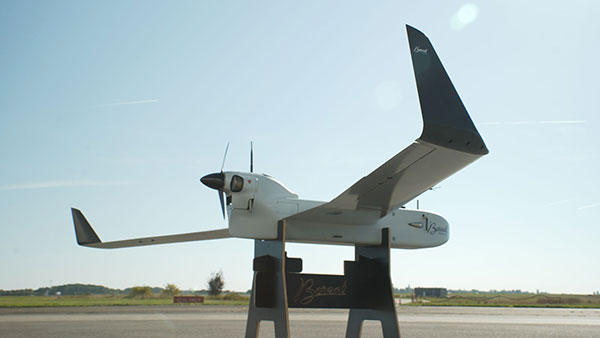
    The Boreal system is a fixed-wing UAV with high-endurance and heavy payload capacity. (Photo: M3 Systems)
    The Boreal system is a fixed-wing UAV with high-endurance and heavy payload capacity. (Photo: M3 Systems)

    The aviation industry is experiencing an innovation upsurge driven by technology and societal pressure for new forms of aviation focused on sustainable, digital and autonomous air mobility. The resulting solutions will generate a significant increase in traffic density in the lower airspace.

    Because existing ATM systems are not designed to handle such volumes or digitalization, coordinating existing and new traffic management systems for brand-new aircraft integration will ensure efficient large-scale operations. This includes commercial, general and drone aircraft for cargo and passenger flights, both crewed and uncrewed.

    The CORUS-XUAM project, funded by the European Union’s initiative Single European Sky ATM Research (SESAR) Joint Undertaking, focuses on solving the challenge of conventional and new traffic management system integration and consists of 19 partners and 11 third parties. M3 Systems, Pipistrel and Volocopter all completed individual flight-test campaigns before this event to bring their aircraft in line with the U-space services.

    A week of flight tests ended with an Open Day air show and presentations. (Photo: M3 Mobility)
    A week of flight tests ended with an Open Day air show and presentations. (Photo: M3 Mobility)

    The CORUS-XUAM flight test conducted at Pontoise airfield near Paris is the third of several flight tests to simulate a variety of real-world scenarios that demonstrate how UTM and ATM intersect with multiple aircraft types.

    Moreover, the CORUS-XUAM project will continue to proactively test and create a safe and controlled lower airspace under the European Union’s ambitious Single European Sky (SES) initiative throughout 2022.

    The successful flight tests at Pontoise airfield were conducted with M3 System’s Boreal remotely piloted aircraft system, Pipistrel’s crewed Velis Electro, the only type-certified electric aircraft in commercial service in the world, and Volocopter’s fullscale, remotely piloted 2X prototype. Pipistrel uses the conventional ATM tower and system while Volocopter and M3 Systems use the UTM system. The following three flight scenarios were tested:

    • The unexpected occupancy of a final-approach-and-takeoff plan and aircraft diversion because of priority landing of another aircraft (Pipistrel and Volocopter aircraft).
    • The diversion of a flight path because of the closure of an airport or vertiport (M3 Systems).
    • The diversion of a flight path with two aircraft flying the same path (M3 Systems and Volocopter aircraft).

    “These successful tests confirm that our Boreal UAS will be an enabler for future XUAM operations in situations where aircraft need to safely divert paths to another vertiport due to an unforeseen closure or another aircraft in the air,” explained Marc Pollina, M3 Systems CEO. “By providing rerouting demonstrations and tactical communications with U-Space service providers, M3 Systems can support future coordination between AAM and airport operators.”

    Pipistrel is “As the manufacturer of the only type-certified electric aircraft in commercial service in the world, proud to take part in technical projects that shape the vision of air mobility and make progress in a meaningful way,” said Gabriel Massey, Pipistrel president. “The CORUS project and Paris demonstrations clearly show how UAM vehicles will be able to fly safely in regular airspace post-2030 and will help to unlock new lower-noise and lower-emission air passenger and air cargo services.”

    In 2019, Volocopter tested its 2X ATM integration at Helsinki airport and was actively involved in the development of the European U-Space Concept of Operations, according to Oliver Reinhardt, Volocopter’s chief risk and certification officer. “Building an efficient ecosystem around UAM is Volocopter’s mission, and connecting ATM/UTM integration with our digital platform, VoloIQ, is poised to be an integral part of bringing UAM to megacities worldwide,” Reinhardt said. “I am looking forward to the next CORUS-XUAM test flights later this year in Germany and what we can achieve there.”

    The project has received funding from the SESAR Joint Undertaking under the European Union’s Horizon 2020 research and innovation program under grant agreement No. 101017682.

  • AUVSI works with Defense on cybersecurity certification for commercial drones

    AUVSI works with Defense on cybersecurity certification for commercial drones

    AUVSI’s Trusted Cyber Program will offer commercial drone certification based on DIU Blue UAS methodology

    Blue UAS logoThe Association for Uncrewed Vehicle Systems International (AUVSI) is collaborating with the Defense Innovation Unit (DIU) to further commercial cyber methodologies to build a shared standard. The standard would be similar to one used to develop DIU’s Blue UAS Cleared List.

    AUVSI’s effort is designed to expand the number of vetted uncrewed aircraft systems (UAS) that meet congressional and federal agency drone security requirements.

    DIU accelerates commercial technology for national security. Its Blue UAS program launched in 2021 is aimed at prototyping and scaling capable and secure commercial UAS technology for the Department of Defense (DOD).

    “The goal of this new pilot initiative is to extend relevant cyber credentialing across the U.S. industrial base, proactively, streamlining and accelerating capabilities available to the DOD and the rest of the U.S. government,” said Brian Wynne, AUVSI president and CEO. “We are grateful for DIU’s partnership and look forward to working with them to make the U.S. drone industry more resilient and secure.”

    AUVSI efforts will streamline the vetting process and expand potential small UAS entrants to the government through its Trusted Cyber Program. The industry-led cyber compliance effort will work with a suite of cybersecurity firms to provide technical cyber assessments. DIU, DOD and other government organizations can then conduct additional vetting if needed.

    The Blue UAS program has helped establish a cybersecurity baseline and coordinate government efforts to streamline the approval process for commercially available NDAA-compliant drones. Thirteen drones are scheduled to be added to the Blue UAS Cleared List, but demand for additional cleared drones with new capabilities has outpaced DIU’s ability to scale this critical program, because of limited funding and manpower. Because of its unique position in the market, AUVSI and its Trusted Cyber Program will provide this cybersecurity certification pathway to the commercial industry in close coordination with DIU.

    “Commercial-off-the-shelf UAS are increasingly relied upon by federal agencies as critical tools to conduct diverse operations,” said David Michelson, DIU program manager for Blue UAS. “Partnerships with industry that make it easier for federal users to access commercial technology will help achieve the program’s goals.”