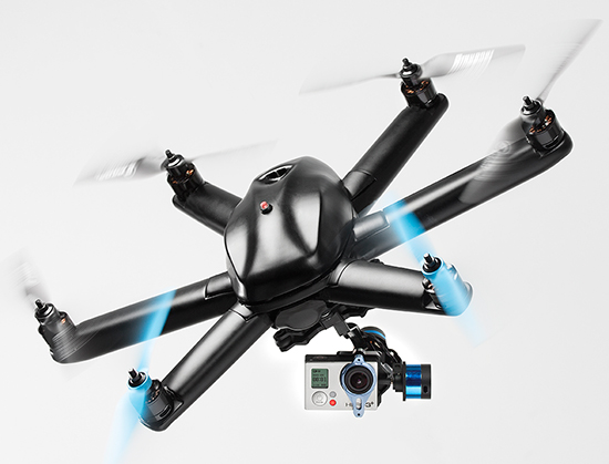
HEXO+, an autonomous flying camera system, by Squadrone Systems will exhibit at CES 2015.
An Unmanned Systems Marketplace debuts this year at the annual International Consumer Electronics Show (CES), being held this week in Las Vegas. The marketplace highlights the burgeoning technology in drones, unmanned aerial vehicles (UAVs), and other unmanned systems controlled by onboard computers or remotely from the ground.
Also, a session on drones will focus on safety and privacy of commercial UAV use.
The Unmanned Systems Marketplace is at CES Tech East, in the Las Vegas Convention and World Trade Center (LVCC), South Hall 2. Tech East includes the LVCC, the Westgate Las Vegas , and Renaissance Las Vegas. Exhibitors at the marketplace include AirDog, Squadrone, Trace, DJI, iRobot, Trace, Torquing Group DBA ZANO, Ecovacs, EHang, Autel, Pelican Products, and other brands.
According to the CES description of the marketplace, “Drones, UAVs and other unmanned systems have taken off as a unique tool for everyday life, regardless of whether flight is controlled by onboard computers or remotely from the ground. Unmanned systems have revolutionized the way we capture, monitor and assist our world. They provide aerial coverage for sports, travel and real estate; enhance search and rescue, law enforcement and disaster relief; and so much more. Experience the variations in design and functionality of this technology with these current exhibitors in the all-new Unmanned Systems Marketplace.”
The session description reads, “The use of unmanned aerial vehicles (a.k.a. drones) for mapping, surveillance, newsgathering, filmmaking, and recreation is on the rise. Drone experts explore commercial and consumer market opportunities — including using drones to deliver packages — and address issues about safety and privacy.”
Record-Breaking Year Ahead: Industry Revenues to Reach All-Time High of $223.2B in 2015
Revenues for the consumer electronics (CE) industry are projected to grow three percent in 2015 and to reach an all-time high of $223.2 billion, according to The U.S. Consumer Electronics Sales and Forecasts, the semi-annual industry report released today by the Consumer Electronics Association (CEA). The total revenues forecast was announced by CEA President and CEO Gary Shapiro during his opening remarks today at the 2015 International CES, running January 6-9 in Las Vegas.
CEA’s consensus forecast reflects U.S. factory sales to dealers and covers more than 100 CE products. The twice-annual report serves as a benchmark for the CE industry, charting the size and growth of underlying categories.
Emerging Technologies
The 2015 forecast projects that revenue for new, emerging product categories is expected to double, growing 108 percent year-over-year in 2015. These new technology categories include unmanned systems (unmanned aerial vehicles, unmanned vehicles and home robots); wearables such as health and fitness devices, smartwatches and smart eyewear; IP cameras; 3D printers; 4K Ultra-High Definition televisions; and connected thermostats.
While the emerging product categories represent less than five percent of the entire CE industry revenue forecast, they are expected to contribute almost $11 billion to overall CE revenue in 2015.
“Our forecast underscores that consumers’ love affair with technology shows no signs of slowing any time soon,” said Shapiro. “Consumer technology is all about continued innovation. In the blink of an eye, consumer demand has taken off for emerging categories such as wearables, unmanned aerial vehicles and 4K Ultra HD — categories that were too small to track just three years ago. Expect to see these burgeoning categories, as well as innovations across the full spectrum of consumer technology, on display this week at the 2015 International CES.”
The Wearable Revolution
The wearable device revolution is a key category to watch in the coming years, and especially in 2015. CEA projects overall wearable unit sales will reach 30.9 million units (a 61 percent increase from last year) and generate $5.1 billion in revenue in 2015 (a 133 percent increase). CEA’s wearables category encompasses fitness activity bands and other health and fitness devices, as well as smartwatches and smart eyewear.
Health and fitness devices: Led by the popularity of activity tracking devices, health and fitness devices will lead unit sales among all wearables in 2015 with a projected 20 million units. Revenue is expected to surpass $1.8 billion in 2015.
Other mobile devices:
Smartphones: As the sales leader of the industry, smartphone unit shipments are projected to reach 169.3 million this year, up six percent from 2014. Additionally, smartphone revenues are expected to generate $51.3 billion in 2015, a five percent increase from last year. Particular growth will be seen in screen sizes between 5.3 inches – 6.5 inches.
Tablets: Unit sales of tablets are projected to reach 80.7 million this year, a three percent increase from 2014. Revenues for tablets will reach $24.9 billion this year, down one percent.
“Mobile connected devices have reached an equilibrium, stabilizing the steep climb these products have experienced in recent years,” said Shawn DuBravac, Ph.D., chief economist, CEA and author of CEA’s soon-to-be released book Digital Destiny: How the New Age of Data Will Transform the Way We Work, Live, and Communicate. “Overall, improving economic conditions, consumer enthusiasm for new features and product categories, competitive manufacturer pricing and several other dynamics now at play should make 2015 an especially significant year for tech.”
Other CE categories expected to enjoy positive growth in 2015 include audio, electronic gaming and laptops. Automotive electronics will see continued growth due to new vehicle sales in 2015, reaching $14 billion in revenue, a 3.3 percent increase.
The U.S. Consumer Electronics Sales and Forecast 2010-2015 (January 2015) is published twice a year, in January and July, reporting U.S. factory sales-to-dealers. It was designed and formulated by CEA to be a comprehensive source of sales data, forecasts, consumer research and historical trends for the consumer electronics industry.
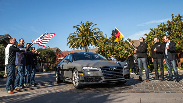
Start of the 550-mile piloted drive from Silicon Valley to Las Vegas: Ricky Hudi, Audi executive vice president electric/electronic development (left) and Ewald Gössmann, excecutive director Electronic Research Lab California (ERL), (third from right) drop the flag for the Audi A7 piloted driving concept car. Photo: Audi
An autonomous Audi A7 is driving itself to Las Vegas for this week’s 2015 Consumer Electronics Show. The Audi is making the 550-mile trip as journalists sit behind the wheel for 100-mile stretches with an Audi official in the passenger’s seat.
The car left Stanford, Calif., Jan. 5 and traversed real-world roads and traffic conditions on its way to Las Vegas.
The long-distance test drive of the Audi A7 piloted driving concept car is designed to show that unprecedented performance can be achieved with series production technology, Audi said in a statement.
“The test drive from the west coast of California to Las Vegas demonstrates our leadership role in piloted driving,” said Prof. Dr. Ulrich Hackenberg, Audi board member and head of technical development. The test drive in real world traffic and road conditions represents a joint effort by the Volkswagen Electronics Research Laboratory (ERL) und Volkswagen Group Research and Development, begins today in Stanford, CA. The Audi A7 piloted driving concept will drive more than 550 miles, approximately 900 kilometers.
The A7 piloted driving concept uses the latest technologically advanced systems developed by Audi. The concept relieves the driver of driving duties from 0 to 70 mph, or just over 110 km/h. The car, named “Jack” by the development team, can initiate lane changes and passing maneuvers. In addition, the A7 piloted driving concept accelerates and brakes independently. Before initiating a lane change to the left or the right, the vehicle adapts its speed to surrounding vehicles. If the speed and distance calculation is deemed safe, the vehicle initiates the lane change with precision and in a timely manner.
The piloted concept vehicle uses a combination of various sensors, many of which are close to production ready. The long range radar sensors of the adaptive cruise control (ACC) and the Audi side assist (ASA) keep watch of the front and rear of the vehicle. Two mid-range radar sensors at the front and rear respectively are aimed to the right and left to complete the 360 degree view. Laser scanners are mounted within the Singleframe grille and the rear bumper skirt. The scanners deliver redundant information to provide detailed recognition of static and dynamic objets during piloted driving. The technologies are production ready including their vehicle integration and cost structure for vehicle production in the near future. A new high-resolution 3D video camera, already integrated into the next-generation systems found in the new Q7, takes a wide-angle view out in front of the vehicle. Four small front and rear mounted cameras view closer surroundings. Navigation data is used for basic vehicle orientation.
Before the piloted driving system reaches its limitations, in city environments for example, the driver is requested to take control of the vehicle to ensure proper safety. Multiple warning signales work in unison: colored LEDs at the base of the windshield, signals in the driver information display, a Central Status Indicator (CSI), as well as a acoustic warning indicator requires the driver to retake control. Should the driver ignore the signals, the system activates the hazard lights and brings the car to a full stop while minimizing any risk. In most instances the vehicle is stopped on the right emergency lane.
The training for the jounalist test drivers taking part in the 550-mile trek took place several weeks ago at the Arizona Proving Grounds. Each journalist will drive approximately 100 miles using the piloted driving system. A trained Audi professional test driver will accompany the media from the passenger seat for added safety.
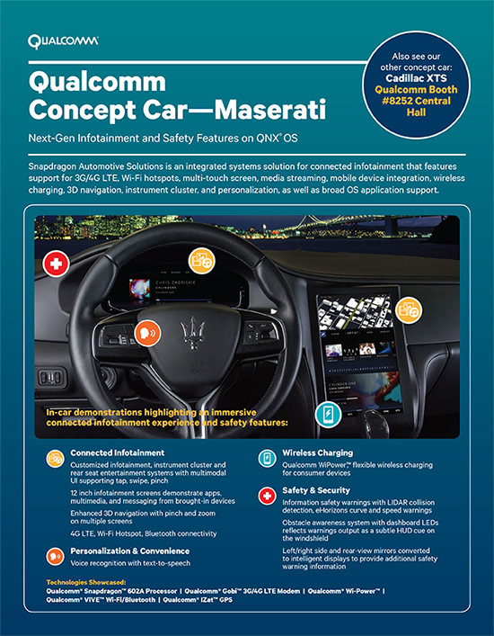
Qualcomm Technologies will demonstrate two new full technology concept cars that integrate Qualcomm Technologies’ latest in vehicle technology and connectivity at the 2015 Consumer Electronics Show, being held this week in Las Vegas. The technology concept cars are based on the 2015 Maserati Quattroporte GTS and the 2015 Cadillac XTS and have been customized to bring the full Snapdragon Automotive Solutions experience to life, including the Qualcomm Snapdragon 602A automotive-grade processor, Qualcomm Gobi 3G/4G LTE wireless modems and Qualcomm VIVE QCA6574 Wi-Fi and Bluetooth module, and Qualcomm IZat RGR7640 GNSS module. Qualcomm Snapdragon and Qualcomm Gobi are products of QTI, and Qualcomm VIVE and Qualcomm IZat are products of QCA.
The Qualcomm Concept Car – Cadillac demonstrates pre-integrated support for Android, including the latest Android L and Kit Kat; high resolution infotainment displays for visually stunning graphics for cluster and infotainment; integrated in-vehicle features, including navigation, music, live streaming of sports, news and entertainment content via LTE-Broadcast; enhanced safety features such as lane detection with integrated navigation, driver distraction avoidance notification, gesture recognition, car personalization via the AllSeen Alliance’s AllJoyn open source framework; wireless audio streaming from personal devices via the Qualcomm AllPlaysmart media platform; smartphone integration and Qualcomm WiPower flexible wireless charging for consumer electronics and; 4G LTE multimode Internet connectivity including WiFi hotspot and Bluetooth profile support.
The Qualcomm Concept Car – Maserati features pre-integrated support for the latest versions of the QNX Neutrino OS and the QNX CAR Platform for Infotainment from QNX Software Systems, a subsidiary of BlackBerry Limited. Highlights include an instrument cluster with speed recommendations, collision warnings, and intelligent parking assist; an infotainment system with 3D navigation, smart phone integration, rear seat entertainment with easy-to-use multimodal UI supporting gestures (tap, swipe, pinch), and voice recognition; an immersive driver experience with rear and side view mirror/displays, complete with refitted cameras and informational safety features; WiPower flexible wireless charging for consumer electronics; and 4G LTE multimode Internet connectivity, including WiFi hotspot and Bluetooth profile support.
Integrated into the technology concept cars are:
Elektrobit’s EB street director navigation software and the latest version of its EB Assist eHorizon Solution with audible and visual warnings and recommendations about the road ahead
TomTom advanced navigation and map services
Jungo’s MediaCore smartphone connectivity and multimedia playback
Rightware’s software and user interface for the instrument cluster
Ricardo’s integrated hardware, controls and electronics
Streaming Internet radio services from Pandora via HTML5 and iHeartRadio via Android
Voice recognition and speech-to-text services powered by Nuance’s Dragon Drive
NXP’s SAF775x AM/FM radio tuner support
QNX Neutrino OS and QNX CAR Platform for next-generation safety and infotainment features
The concept cars are on display at CES, located at the Las Vegas Convention Center, Central Hall, Booth 8252 and Central Plaza, Booth CP21A.
Nexcom introduces in-vehicle computers VTC 7230 and VTC 7240 to foster the growth of connected vehicles in the IoT (Internet of Things), which aims to offer safer and more efficient driving experience. Featuring fifth-generation Intel Core processors, the in-vehicle computers have numerous telematics features to support fleet management, security features to protect vehicles in the IoT, and performance to drive ADAS (Advanced Driver Assistance Systems) and stream multiple video surveillance feeds.
For fleet management, VTC 7230 and VTC 7240 feature built-in GPS for vehicle tracking and navigation, and a CAN bus 2.0B interface with optional OBD II function for vehicle diagnostics. To enable remote monitoring of vehicle diagnostics, store and exchange data of video surveillance feeds and IVI (In-Vehicle Infotainment) services, VTC 7230 and VTC 7240 feature four mini-PCIe expansions with dual WWAN support and dual external HDDs, providing high cellular bandwidth for fast connections and ample storage for large video and media files.
“The pursuit of driving safety and efficiency has been the driving force for advancements in in-vehicle technologies,” said Steven Wu, general manager of Nexcom’s Vertical Industry Platform (VIP) Business Unit. “Using fifth-generation Intel Core processors i3-5010U and i7-5650U respectively, VTC 7230 and VTC 7240 provide signal processing, machine vision, and video transcoding capabilities required of ADAS, ANPR (Automatic Number Plate Recognition) and video surveillance, giving abilities to sense and to think to fleet transport, public transport, police vehicles, ambulances and more.”
“The fifth-generation Intel Core processors utilizing Intel’s new 14nm process has integrated Intel HD graphics 5500 and 6000 and expanded hardware security. Its excellent performance adds multitasking capability for compute-intensive applications such as Advanced Driver Assistance Systems (ADAS), while the Intel Quick Sync Video provides fast transcode time. Furthermore, hardware security design, Intel OS Guard and Intel AES-NI, helps protect systems against malware intrusions and helps accelerate data encryption.” said Samuel Cravatta, IOTG product line director, Intel.
For added physical security, the pre-alarm function on the in-vehicle computers features two DI and DO channels and an event button signal that can both operate in power-off state, ensuring alarms and emergency notifications are constantly available at times of intrusion or urgent conditions.
For fleet management, VTC 7230 and VTC 7240 feature built-in GPS for vehicle tracking and navigation, a CAN bus 2.0B interface with optional OBD II function for vehicle diagnostics. Furthermore, to enable remote monitoring of vehicle diagnostics, store and exchange data of video surveillance feeds and IVI (In-Vehicle Infotainment) services, VTC 7230 and VTC 7240 feature four mini-PCIe expansions with dual WWAN support and dual external HDDs, providing high cellular bandwidth for fast connections and ample storage for large video and media files.
Tracking device maker Trackimo will make its official North American debut at a press conference on Jan. 7 during the 2015 Consumer Electronics Show in Las Vegas. At the press conference Trackimo will showcase its new line of tracking devices that will be introduced throughout 2015. Trackimo will also announce its partnership with Trackimo North America as an exclusive U.S. and Canadian distribution partner.
Trackimo was founded and is based in Israel. The company already has distribution deals in Latin America, Europe and Israel. The new distribution partnership in North America will offer its product to the mass market, according to Trackimo.
“We are very excited to be able to provide Trackimo’s cutting-edge technology at an entirely new price point that virtually sets a new mass market segment for tracking devices,” said Shai Bar-Lavi, CEO and Chairman of Trackimo, Inc. “We offer a whole new approach to tracking that enables consumers to use our products and services in ways that were not possible before.”
“We’re very excited to be part of the Trackimo Worldwide team and to be launching Trackimo into the North American market,” says Jim Prandine, vice president of sales, Trackimo North America. “Trackimo Universal covers dozens of applications in various channels, and our new upcoming products will broaden consumer demand even further.”
Bar Lavi added, “We are very excited about this new partnership with Trackimo North America as it opens up limitless opportunities for the Trackimo brand.”
Debuting at CES:
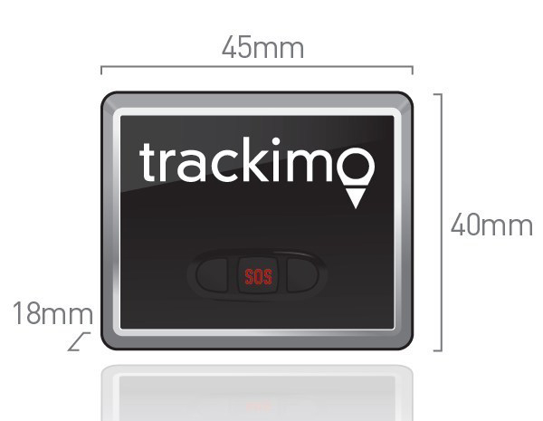
Trackimo Universal: A compact (45 x 18 x 40 millimeter), lightweight device with long-lasting battery life and worldwide service. Included accessories allow users to secure Trackimo device to different objects, including backpacks, bikes, belts and luggage. Trackimo Universal can also be hardwired in a car, eliminating the need for charging. Designed for outdoor use, the Trackimo device also includes accessories for waterproofing.
The Trackimo app offers a single-point login for both computers and mobile platforms to allow effortless management of tracking units. It offers multiple device management under a single account, as well as, a variety of remote settings options.
Highlights of Trackimo’s products include:
Dynamic Tracking Frequency: User-controlled location sampling enables optimized energy consumption.
Smart Alerts: User alerts via text, email and app notifications for location change, speed thresholds, sudden movement or impact, or SOS button press.
Dynamic History: All tracking history is stored; user can recall any time period and select from a variety of time resolutions.
GPS Tracking: Highly accurate locations when GPS reception available, but capable of accurate tracking wherever cell phone reception is available.
Virtual Fences: User-defined “geofences” give notifications when specific boundaries are crossed.
Multiple Devices: Multiple devices can be simultaneously tracked and managed on a single account.
Coming soon: Emergency Voice Channel: Voice channel can be opened automatically when SOS button is pressed, allowing remote user to hear what’s happening on site.
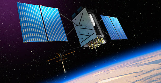
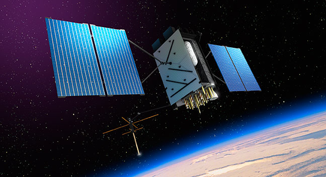
Artist’s rendering of GPS III satellite (courtesy of Lockheed Martin).
Raytheon Company and Lockheed Martin successfully completed the fourth of five planned launch and early orbit exercises to demonstrate new automation capabilities, information assurance and launch readiness of the U.S. Air Force’s next-generation GPS III satellite and Operational Control System (OCX).
Successful completion of Exercise 4, on Oct. 3, represents a key milestone demonstrating the end-to-end capability to automatically transfer data between Raytheon’s OCX and Lockheed Martin’s GPS III satellite. One additional readiness exercise, five launch rehearsals and a mission dress rehearsal are planned prior to launch of the first GPS III satellite with OCX.
The exercise used the latest baseline of Raytheon’s OCX Launch Checkout System (LCS) software featuring integrated information assurance functionality for the first time and the latest version of Lockheed Martin’s GPS III satellite simulator. Exercise 4 successfully demonstrated mission planning and scheduling capabilities with the simulated Air Force Satellite Control Network (AFSCN) for the first time, including a replan scenario that would occur in the event of a launch slip.
The system also automatically generated antenna pointing angles for the simulated AFSCN, which until now have been manually generated. Exercise 4 expands on three previous exercises, introducing maneuver planning and reconstruction capabilities, as well as advanced planning and scheduling with AFSCN assets. The automation of these capabilities will allow GPS operators to spend their time optimizing system performance rather than focusing on routine operations.
“As part of establishing the LCS Block 0 baseline, the completion of Exercise 4 demonstrates the capability of OCX to successfully support a GPS-III satellite launch in an information assurance hardened environment,” said Matthew Gilligan, Raytheon vice president and GPS OCX program manager. “Exercise 4 began the instantiation of vital OCX automation capabilities that give operators their time back in order to focus on mission critical activities, one of the important elements of a modernized GPS.”
“Launch Exercise 4 demonstrated the team’s ability to complete nearly 100 percent of the GPS III space vehicle 1 launch and early orbit mission sequence,” said Mark Stewart, vice president for Lockheed Martin’s Navigation Systems mission area. “The findings the team made during this robust launch exercise will help mature the processes, procedures, and tools necessary to enter our rehearsal phase and ultimately the launch and checkout mission.”
GPS III satellites will deliver three times better accuracy, provide up to eight times improved anti-jamming capabilities, and include enhancements that extend spacecraft life to 15 years, 25 percent longer than the newest Block IIF satellites. GPS III will be the first generation of GPS satellite with a new L1C civil signal designed to make it interoperable with other international global navigation satellite systems. The first GPS III satellite is currently undergoing integration and testing, with final space vehicle delivery planned for late 2015.
OCX is being developed in two blocks using a commercial best practice iterative software development process, with seven iterations in Block 1 and one iteration in Block 2. Exercise 4 was conducted using the recently completed Iteration 1.5 software, representing an early delivery of the final software baseline. Exercise 5, scheduled for 2015, will include critical information assurance features needed to support launch of the first GPS III satellite.
Wi2Wi Corporation is releasing the W2SG0021i, a miniature GNSS module based on the CSR SiRFStarV chip.
The W2SG0021i is a high-sensitivity, low-power stand-alone receiver designed for portable applications. It can concurrently track multiple satellite constellations (GPS, GLONASS, BDS, SBAS, and is Galileo-ready) and has ultra-fast time-to-first-fix, a small form factor, and high receive sensitivity for a broad spectrum of OEM products, including machine-to-machine (M2M) and consumer wearables.
The module provides precision commercial-grade GNSS location identification over -40C to +85C. Measuring 7 x 7 millimeters, the W2SG0021i addresses the need for a cost-effective and high-performance GNSS module for major markets worldwide, the company said.
M2M and wearable markets require GNSS modules with high position accuracy, low power, and very small form factor, said Wi2Wi CTO and vice president of engineering Tony Fardanesh. Wi2Wi pushes these limits in its GNSS, Wi-Fi, and Bluetooth solutions, he said.
Precision location features and the small form factor of W2SG0021i enable Wi2Wi to penetrate into the GNSS market globally. Wi2Wi continues to invest in the research and development of high-precision connectivity solutions, timing devices and frequency controllers to the global customer base, said CEO Hans Black.
The W2SG0021i samples and development kit will be available in Q1 2015.
Wi2Wi designs, manufactures and markets miniaturized embedded wireless connectivity solutions (incorporating both hardware and software), high-precision timing devices, and frequency controllers for premium industrial/medical, avionics, home automation and government markets.
Concerns raised about cascaded Kalman filters for loose coupling and/or usage of input data “massaged” in unknown ways are not new, but are routinely excused by requirements to use coordinates from receivers not providing measurement outputs. Often, however, a receiver’s internal 8-state extended Kalman filter (EKF) is not fed with precise carrier phase data — and even when it is, its velocity outputs (being both filtered and unaided) have limited ability to follow high dynamics. Velocity pseudomeasurements under those conditions interfere with IMU aiding.
The extent of reduction in capability of course depends upon the equipment (widely varying and beyond reach of the user) and upon the scenario. Not only flight paths but any trajectory with sharp changes in speed or direction are affected. Twisting, jerking, and winding motions actually experienced can be reported as having reduced severity, and attitude history will suffer further inaccuracy. A demand to accommodate loose coupling is then best satisfied by pseudomeasurements in position only.
This is not an attempt to coax an entire industry into abandoning a very popular choice for satnav/inertial measurement unit (IMU) integration. By “what’s wrong with it” I mean how it’s often done. Believe it or not, there’s a fundamental self-defeating trait in current practice.
Admittedly, I gave short-shrift to loose coupling in my 2007 book GNSS Aided Navigation & Tracking; all flight data processing results in it were for tight coupling with carrier phase (actually, 1-second changes in phase) included. Some years ago, though, I reran segments from that flight, including takeoff and another segment containing a 180-degree turn, with only latitude/longitude/altitude (LLH) pseudomeasurements and no carrier-phase information. Not surprisingly, it provided accuracy commensurate with quality of the LLH input (how could it not?). With heading info added, the velocity errors (peak transients of a few meters/second near start and end of the turn; otherwise smaller) and leveling accuracies (a few mrad) were likewise commensurate with input quality.
I never bothered to publish that; the world doesn’t need more testimony for ability to convey data obtained from a receiver with satellite visibility favorable throughout.
I avoided, however, using pseudomeasurements of velocity. Precisely therein lies the target of this critique: velocity from a receiver’s internal 8-state EKF, fed only from position-dependent measurements in the form of pseudoranges. More broadly, this focuses attention on receivers wherein carrier-based information is either unused (immediately below), imprecise (for example, by using deltarange or cutting corners in other ways), or filtered (thus correcting with averaged past, rather than near-instantaneous, derivative data).
First, velocity observables derived exclusively from the same inputs providing position create a glaring violation of independence — but there’s also a bigger issue: Velocity pseudomeasurements with that scheme constitute a basic contradiction of inertial aiding. A main purpose of the IMU is to reveal dynamics with promptness that data derived from pseudorange histories can’t match. Allow me to review some fundamentals here.
At UCLA more than a half-century ago, I taught undergraduate lab experiments. One illustrated under-/over-/critically damped response, a concept so familiar that no math is needed to explain it. Any application will suffice; that experiment involved control of a motor shaft position. A simple transfer function applied to the position feedback signal determined the damping. With all feedback derived from position, either critical or slight underdamping was de rigeur.
Addition of rate aiding (for that experiment, a tachometer) dramatically improved response without degrading accuracy. The obvious reason: it was no longer a choice between responsiveness versus accuracy. Both are available when an independent rate sensor accompanies the position indicator.
Now, consider redesigning that controller’s rate portion of the feedback signal, giving dominance to sequential changes in position. Unless both highly precise and independent, that would curtail the benefit (that is, improved response to dynamic change) of adding measured rate. Degradation would also arise from giving dominance to a more crudely approximate and/or heavily filtered indication of rate.
There are differences between that example and satnav/IMU integration (for example, estimation versus control; time-varying versus constant gains; and so on) but the principle remains applicable. When derived rate from that 8-state Kalman filter is used to correct (thus overrule) the velocity history, the responsiveness to dynamics offered by the IMU is being undermined by a process that’s beyond reach. The system’s position and velocity then draws nearer to the output of an unaided (standalone) receiver.
The practice raises various questions:
Is that an integrated approach worthy of the name? Or doesn’t the IMU just derive attitude adjustments by riding piggy-back — thereby taking (velocity history from an unaided receiver) without giving (unimpeded improvements in response to dynamics, as expected from inertial aiding)?
How good is that system’s accuracy (not in position; in velocity and in leveling — and not from simulation; from flight data with dynamics)?
If LLH data were replaced by pseudoranges for tight integration, would velocity pseudomeasurements still be used, to give coupling tight for position but loose for velocity?
(I hope not.)
Since velocity pseudomeasurements are unnecessary in tight integration without carrier phase data, then why use them with LLH?
I’ll turn that last item into a recommendation for satnav/IMU suppliers hoping to compete successfully: If you must include a loosely coupled mode to accommodate LLH-cum-velocity data from a receiver’s 8-state EKF, don’t use receiver velocities as observables. Your system outputs will evolve without them.
Appropriate design is required (you’ll have to do more than just disconnect the velocity inputs) but, given that, all information will be extracted from the IMU and LLH data — with inertial aiding in high dynamics unobstructed by superfluous (8-state-derived) velocity data. Accuracy will improve in not only velocity but also attitude — from simpler software.
An objection might be raised, noting fair performance when exploiting the full 8-state information if dynamics are always mild. To that I would answer: Is there no limit to how much performance will be sacrificed just to accommodate expediency? Loose coupling already forfeits robustness. Let’s not compound that by surrendering dynamics as well. All of us realize the large, and growing, array of obstacles disrupting successful operation. Why design only for benign conditions? Approaches taking advantage of advances beyond exploiting separate pseudoranges (usage of precise carrier phase, ultratight coupling, FFT-based deep integration) remain ever more in the minority, despite myriad threats to GNSS.
This discussion has concentrated on unnecessary limitations of loosely coupled GNSS/INS integration performance as commonly practiced. Similar problems in systems with tighter integration are less prevalent but still not uncommon (for example, inertial instrument error modeling is still not widely understood, and attitude accuracy reported from many sources doesn’t reach achievable levels. Those familiar with my writings are aware of various changes I would advocate, not limited to inertial or satellite navigation. Those and other issues will be left to another time.
James L. Farrell worked for 31 years at Westinghouse in design, simulation, and validation of navigation and tracking programs. He teaches and consults for private industry, the Department of Defense, and university research through Vigil, Inc.
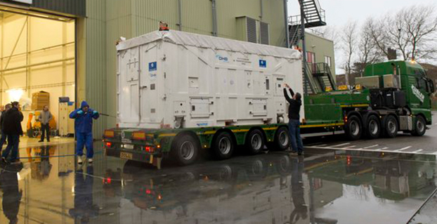
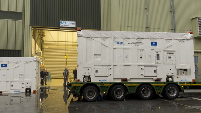
The latest Galileo satellite, formally known as FOC FM06, arrived at the ESTEC Test Centre in its protective container on Dec. 18, after traveling from OHB in Bremen, Germany. Photo: European Space Agency
The latest Galileo satellite has arrived at ESTEC, in the Netherlands, and is undergoing a full checkout to prove its readiness for space.
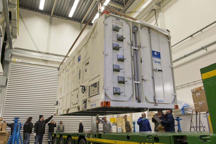
The satellite was carried by lorry from its manufacturer in Germany, cocooned within an environmentally controlled container. It arrived inside ESTEC’s cleanroom environment on Dec. 18. The container was then opened up to begin preparations for testing.
The first six Galileo satellites are already in orbit, launched in pairs in 2011, 2012 and August this year.
The last pair was delivered into the wrong orbit by a faulty upper stage, but the fifth satellite’s orbit has since been changed to allow checking of its navigation payload, which began at the end of November.
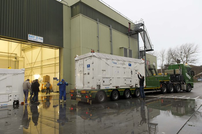
The sides and top of the Galileo satellite container were sprayed clean before it was taken inside the bay of the ESTEC Test Centre to keep any contamination from entering the pristine cleanroom. Photo: European Space Agency
Meanwhile, down on the ground, production of further satellites continues steadily, taking the Galileo series into double figures overall.
Following on from the first four In-Orbit Validation satellites, 22 of these Full Operational Capability satellites are being built by OHB in Bremen, Germany, with navigation payloads from SSTL in Guildford, UK.
Numbered Flight Model 6, or FM06 for short, this latest of the newer satellites is now reunited under the test centre’s roof with three others. FM03 and FM04 have completed their acceptance testing, culminating in the weeks-long thermal-vacuum test. Each satellite was subjected to the same vacuum and extreme temperature conditions experienced in orbit, as well as radio-frequency testing of their navigation payloads and antennas inside an anechoic chamber isolated from the external universe. This pair is now in storage in the centre pending the results of their concluding acceptance review.
The other satellite, FM05, recently ended its own thermal-vacuum trial. It is now being reconfigured for radio-frequency testing, planned to take place after the Christmas break. The latest unboxed Galileo satellite will undergo its own thermal–vacuum test in January.
ESTEC is an essential stop on the way to space for Galileo. It is equipped with all the facilities needed to simulate space conditions under a single roof, including an acoustic chamber, earthquake-strength shaker tables, and anechoic and vacuum chambers, along with a range of specialised measuring equipment.
Once ESTEC gives the satellites its stamp of quality then they are in principle ready to be flown to Europe’s Spaceport in Kourou, French Guiana. ESA and the European Commission are currently deciding on the launch schedule for these next Galileos.
The container containing the latest Galileo satellite, FOC FM06, was carefully hoisted off the lorry that carried it from OHB in Bremen, Germany. Its underside was then carefully cleaned before it was taken out of the bay into the cleanroom environment. Photo: European Space Agency
Satellite TV pirates beware: Broadcom Corporation is offering a GPS-enabled satellite outdoor unit (ODU) device that gives satellite TV providers a way to track subscriber equipment, pinpoint service issues in the home, and stop piracy with a geo-lock. The solution will also enable delivery of location-based services.
The ODU solution combines Broadcom’s BCM4551 satellite TV device with its BCM4771 GPS receiver.
Broadcom’s new satellite solution resides in the low-noise block (LNB) of a subscribers’ satellite dish, enabling operators to better position dish installations and reduce metering equipment costs and truck rolls. Combining GPS-enabled ODU technology with a set-top box, operators can quickly locate and validate a subscriber’s home location, Broadcom said.
“By combining Broadcom’s field-proven satellite ODU technology with GPS functionality, we are able to provide operators with the capability to more conveniently and cost-effectively track the location of their equipment and prevent redistribution of content to nonsubscribers,” said Nicholas Dunn, Broadcom vice president of Direct Broadcast Satellite Marketing. “This integrated technology can also open the door to operator delivery of location-based social media and business applications, providing subscribers with targeted content such as information on local service providers, retail operations and restaurants, or a specific televised event.”
GPS technology within the LNB also allows operators to geo-lock content to subscribers. Content geo-locking uses a subscriber’s location to deliver video content specific to the subscriber’s service address. This ensures the delivery of personalized services and prevents costly theft of service for operators. Previously, content geo-locking was only available through a costly external device attached to subscriber’s set-top box; today’s introduction from Broadcom offers best-in-class capabilities at an incremental cost for operators.
Key Features of the BCM4551
Highly-integrated 28 nanometer (nm) process with low power consumption
Allows 24 DVB-S2 channels to be stacked on a single coaxial cable to service any STB to reduce satellite operator installation costs
8 RF inputs and 1RF output covering the 250 to 2350 MHz frequency range
24 user-band output channels
24 output channels selectable from any LNB input
Frequency shift keying (FSK) and digital satellite equipment control (DiSEqC)
Key Features of the BCM4771
Highly integrated radio frequency (RF), baseband processor and CPU with smallest complete PCB footprint
Faster signal searches, accurate real-time navigation and improved tracking sensitivity
Increased satellite availability: supports GPS, and GLONASS satellites at L1 frequency band.
Broadcom will demonstrate the new solution at the International CES show, January 6-9.