Enter GPS III. The long-awaited navigation payload for the next-generation satellite pulled into its new temporary home over the September 13 weekend, the Lockheed Martin Space Systems facility in Littleton, Colorado. Lockheed is the U.S. Air Force’s prime contractor for the first batch of eight GPS III satellites.
Exelis Geospatial Systems has committed to delivering the payloads for the second, third, and fourth GPS III satellites “right on the heels” of the first, according to Gen. John Hyten, commander of Air Force Space Command. “If that’s the case, in the not-too-distant future GPS III will be in good shape,” he added. The first GPS III launch is now scheduled for 2016.
Exelis has built GPS payloads since the beginning of the program, but found new challenges over the last two years posed by advanced features of the modernized version. “First-time development and integration issues, including design changes to eliminate signal crosstalk” have set back the schedule.
According to reports, Lockheed Martin has a group of initial platforms readied on its production line to take the incoming payloads.
Still ahead, completion of acceptance testing following integration with the first satellite platform.
Earlier this year, Lockheed Martin issued a request for information on alternate payload providers, and received responses from five companies. In June, the Air Force issued a call for contractors interested in building the next batch of GPS IIIs. Northrop Grumman and Boeing have responded.
The seventh GPS-IIF satellite, SVN-68/PRN-09, launched on August 2, was set to healthy and usable Sunday night, according to Rick Hamilton, CGSIC executive secretariat of the USCG Navigation Center. The change brings the number of satellites transmitting the L2C signal to 13, and those transmitting the L5 signal to seven.
The next GPS-IIF satellite, IIF-8/SVN-69, is tentatively scheduled for launch on October 29.
Below is the full text of the Notice Advisory to Navstar Users (NANU).
NOTICE ADVISORY TO NAVSTAR USERS (NANU) 2014071
SUBJ: SVN68 (PRN09) USABLE JDAY 260/2026
1. NANU TYPE: USABINIT
NANU NUMBER: 2014071
NANU DTG: 172024Z SEP 2014
REFERENCE NANU: N/A
REF NANU DTG: N/A
SVN: 68
PRN: 09
START JDAY: 260
START TIME ZULU: 2026
START CALENDAR DATE: 17 SEP 2014
STOP JDAY: N/A
STOP TIME ZULU: N/A
STOP CALENDAR DATE: N/A
2. CONDITION: GPS SATELLITE SVN68 (PRN09) WAS USABLE AS OF JDAY 260
Robert Dumont, international sales manager at Antcom Corporation, discusses the rugged GNSS and communication antennas as well as the microwave accessories Antcom manufactures while at the 2014 ION GNSS+ Conference September 9-12 in Tampa, Florida.
RIA Novosti is reporting that negotiations regarding the placement of a differential correction and monitoring GLONASS station in the United States have not yet been renewed. The news agency quotes remarks by Grigory Stupak, first deputy general designer of Russian space systems, during the Fourth International School on Satellite Navigation.
In all, 40-50 GLONASS stations are planned for placement around the world, Stupak said. “As for the United States, we now consider the option of placing a station in Alaska, but the lack of it does not significantly affect the performance of our system,” he said, adding that Russia has worked with the southern African region and South America on placement of GLONASS stations, with one station in Brazil already operational. “There also have Cuban colleagues to host GLONASS stations,” he said.
According to Stupak, taking into account developments in the world, it does not make sense to force the negotiation situation by placing a station in Alaska.
GLONASS Satellites Based Mainly on Russian Component Base
The prevailing share of the payload for both GLONASS-M and GLONASS-K spacecraft is created by JSC Russian Space Systems (CSW), but contains an element base of both domestic and foreign production, Stupak said, according to the the GLONASS Herald.
“If you take onboard equipment [for] GLONASS-M, a significant portion of its designers develop mainly on electronic components of domestic production,” Stupak said.
Including onboard equipment, while a significant portion of the GLONASS-M design is based on domestic electronic components, for the GLONASS-K, most of the components are Russian, but some foreign components are also being used.
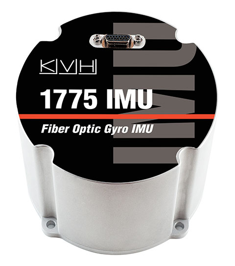
KVH Industries, Inc., has introduced the 1725 Inertial Measurement Unit (IMU) and the 1775 IMU, advanced sensors designed to be integrated into the most demanding stabilization, pointing, and navigation applications. These two new products complement KVH’s successful 1750 IMU and create a complete range of choices for advanced six-degrees-of-freedom (DOF) sensors with enhanced performance. All three products utilize the E•Core ThinFiber technology of KVH’s DSP-1750 fiber-optic gyro (FOG).
“With these three products, system designers and integrators now have a high-performance solution for every application — ranging from manned and unmanned commercial and defense platforms, optical equipment stabilization systems, and pipeline inspection equipment, to autonomous vehicle control and navigation,” said Jay Napoli, KVH’s vice president of FOG/OEM sales. “This line satisfies the performance, size, and price parameters for IMUs in a way that no competitor can match due to KVH’s control over the design and manufacturing process, from creating the fiber to integrating all of the IMU components into the final design. Maintaining complete control of this process, combined with our proprietary technologies, allows KVH to offer a winning combination of innovative solutions, superior quality, and affordable options for nearly every stabilization or guidance application.”
The 1725 IMU features a flexible user interface, with user programmable data output rates from 1 to 1000 Hz. It delivers excellent FOG performance and stability at a price comparable to competitive MEMS-based IMUs. The 1725 IMU is designed for all platforms and navigation or stabilization systems where low cost, high-performance, and high bandwidth are critical for success.
The 1775 IMU is a premium sensor designed to deliver the highest level of performance to meet the demands of platforms requiring superior performance in the most challenging environments. Providing ease of integration for designers of high-level inertial navigation, guidance, or stabilization systems, the 1775 IMU offers a flexible interface with user-programmable data output rates from 1 to 5000 Hz. It includes three axes of magnetometers for automatic gyro bias compensation even in the presence of strong magnetic fields. The 1775 IMU is designed for sophisticated systems and applications where very high bandwidth, low latency, and extreme stability are critical.
Like KVH’s 1750 IMU, introduced in 2012, the 1725 IMU and the 1775 IMU incorporate three axes of KVH’s DSP-1750 FOG, a tiny high-performance FOG integrated with three axes of advanced accelerometer technology. All three IMUs provide excellent shock, vibration, and thermal performance, as well as a compact form factor, KVH said.
KVH controls the entire production process, from creating its own specially designed polarization-maintaining optical fiber to packaging its gyros together in advanced systems for inertial measurement, inertial navigation, and attitude heading reference. As a result, KVH’s open-loop fiber optic gyros offer outstanding accuracy and excellent durability at a lower cost than competing systems, the company said.
Michael B. Mathews, Ph.D., CEO and founder of Loctronix, details the company’s Interference Detection System (IDS) at the ION GNSS+ September 9-12 at the Tampa Convention Center in Tampa, Florida.
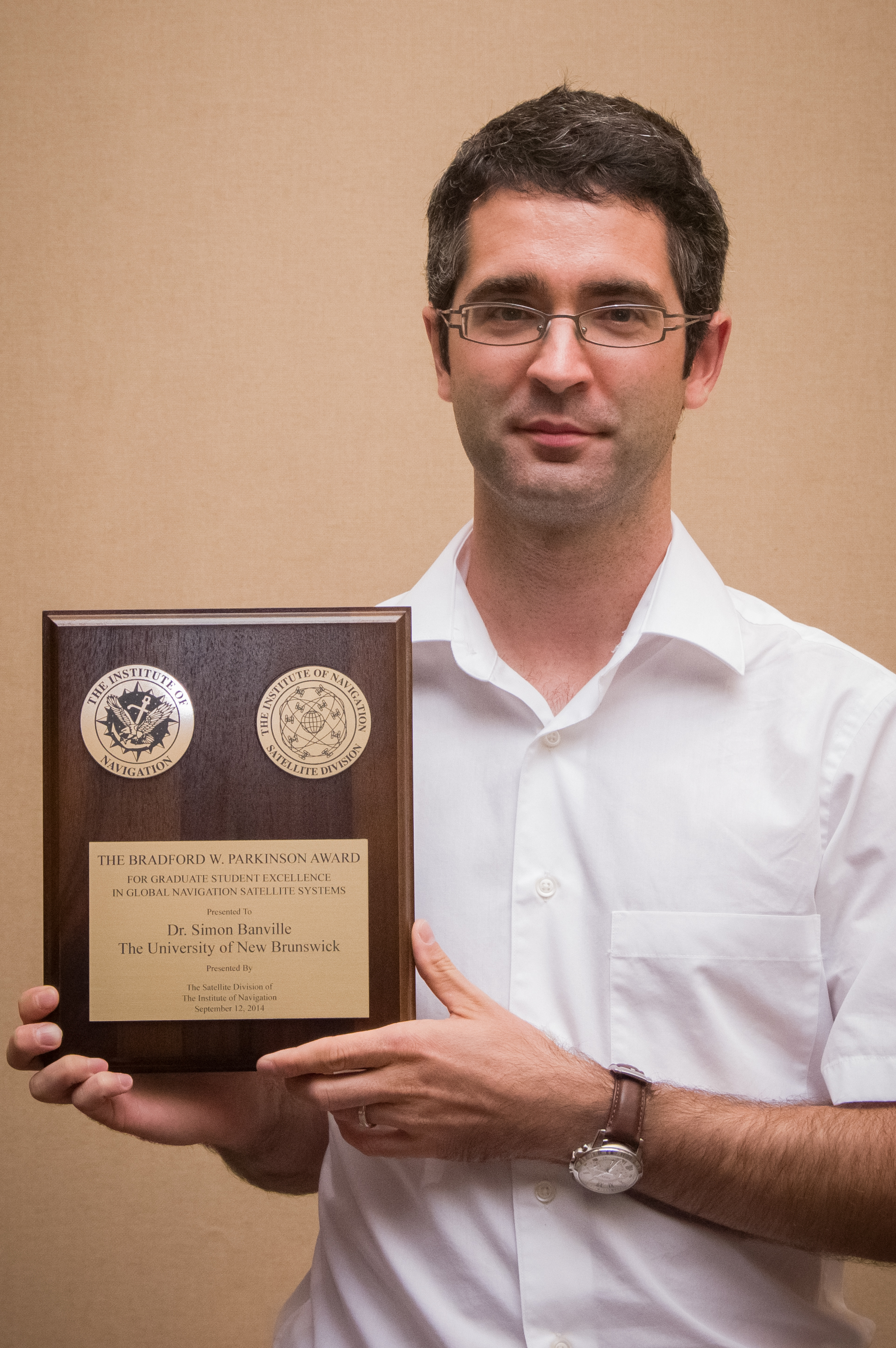
The $2,500 honorarium and plaque was presented recently during The Institute of Navigation’s GNSS+ meeting in Tampa, Florida.
The Parkinson Award recognizes an outstanding graduate student in the field of global navigation satellite systems, such as the Global Positioning System. The winner is selected based on the theses and dissertations submitted by supervisors from the global GNSS research community.
Banville was selected for his outstanding contributions that represent truly significant innovations in the technology, application, or policy of modern satellite navigation systems. Supervised by UNB’s Dr. Richard Langley, his dissertation is entitled Improved Convergence for GNSS Precise Point Positioning.
The award honors Dr. Brad Parkinson for his leadership in establishing both the U.S. GPS and the Satellite Division of the ION.
Ph.D. student Simon Banville and Prof. Richard Langley.
Precise Point Positioning or PPP is a relatively new single-receiver positioning technique that uses precise information on the orbits of navigation satellites and the atomic clocks they carry along in a rigorous mathematical model for analyzing receiver measurements. It permits positioning accuracies down to the few-centimetre level and Mr. Banville’s improvements to the technique will have significant economic benefits for those using GNSS in high-precision applications.
Banville will receive his Ph.D. degree at UNB’s Fall Convocation next month.
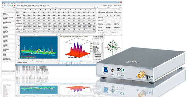
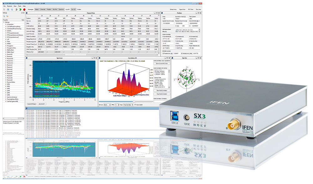
IFEN has launched the SX3 receiver. The company’s previous scientific software receiver, the SX‐NSR, was subject to major upgrades, while the respective hardware front-end was completely redesigned. Together, they build the new SX3 GNSS software receiver.
IFEN’s most important innovation of the year was introduced at the ION GNSS+ Conference September 9-12 in Tampa, Florida.
One of the SX3’s key features is four RF frequency bands, which can be split into a maximum of eight sub-bands per unit. This enhances the bandwidth to a full 55 MHz per RF band, offering additional signal power, especially in E5 band. The new USB 3.0 port empowers a unrivaled data transfer rate that makes a maximal bit-quantization of up to 8-bit possible — for every single stream.
The additional power is compressed into a significantly smaller and lighter hardware chassis than before. Among other options, a dual antenna-input feature can be ordered as well as an OXCO clock. (Standard equipment of the SX3 GNSS software receiver is a precise temperature-controlled oscillator.)
The proofed difference correlator notably ruggedizes acquisition and tracking of any navigation satellite signals. Polyfit tracking reduces measurement noise through averaging (such as code/carrier measurements). (See “Innovation: Software GNSS Receiver.”) Accordingly, vector tracking improves the tracking of weak signals in degraded environments and the reacquisition of “lost” satellites.
Just like its predecessor, it is also able to act as a framework for a customer’s own signal processing algorithms. “Customers can fully concentrate on their applications instead of dealing with potentially obscure code when using open source,” said Product Manager Bernhard Riedl. “Our professional support is specifically dedicated to scientific work as well as SX3’s capability for additional customizations. SX3 is far more than just a COTS product. This makes IFEN’s new SX3 scientific software receiver a mighty powerful tool for research and development.”
Jay Napoli, vice president of FOG/OEM sales for KVH Industries, Inc., chats with GPS World about fiber-optic gyros (FOGs) while at the ION GNSS+ Conference September 9-12 at the Tampa Bay Convention Center in Tampa, Florida.
Carolyn P. McDonald, president and CEO of NavtechGPS, catches up with GPS World at the ION GNSS+ Conference September 9-12, 2014, at the Tampa Convention Center in Tampa, Florida. Franck Boynton, vice president and CTO of NavtechGPS, also shares about simulators with software, the company’s OEM presence and more.
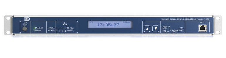
The SEL-2488 satellite-synchronized network clock. Photo: SEL
SEL has released a new network clock designed for critical infrastructure and harsh environments. Model SEL-2488 receives GNSS time signals and distributes precise time via multiple output protocols, including IRIG-B and NTP.
The SEL-2488 provides time-delay compensation for antenna cables and output cables on per-port basis to further optimize time distribution accuracy. For security, the clock features the Syslog Ethernet standard for event messaging, role-based accounts and LDAP for user authentication, and secure HTTPS web interface.
The clock synchronizes with precise time accuracy to within ±40 nanoseconds to UTC for power protection applications. The standard TCXO holdover accuracy is 36 µs/day and the optional OCXO holdover accuracy is5 μs/day.
Time can be distributed from eight time outputs configurable for IRIG-B or time pulse outputs. The SEL-2488 also includes four standard Ethernet ports, which provide NTPv4 and are available in copper as well as single- or multimode fiber.
With Satellite Signal Verification, the SEL-2488 uses signals from a second satellite constellation to validate the GPS time signals, providing a layer of protection from GPS spoofing attacks. The SEL-2488 also provides an option for a second, redundant power supply and operates in a temperature range of –40° to +85°C (–40° to +185°F).
The SEL-2488 supports DHCP with a captive portal, LDAP, an HTTPS device webpage, and acSELerator QuickSet SEL-5030 software for easy and secure configuration.
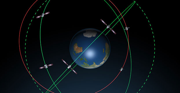
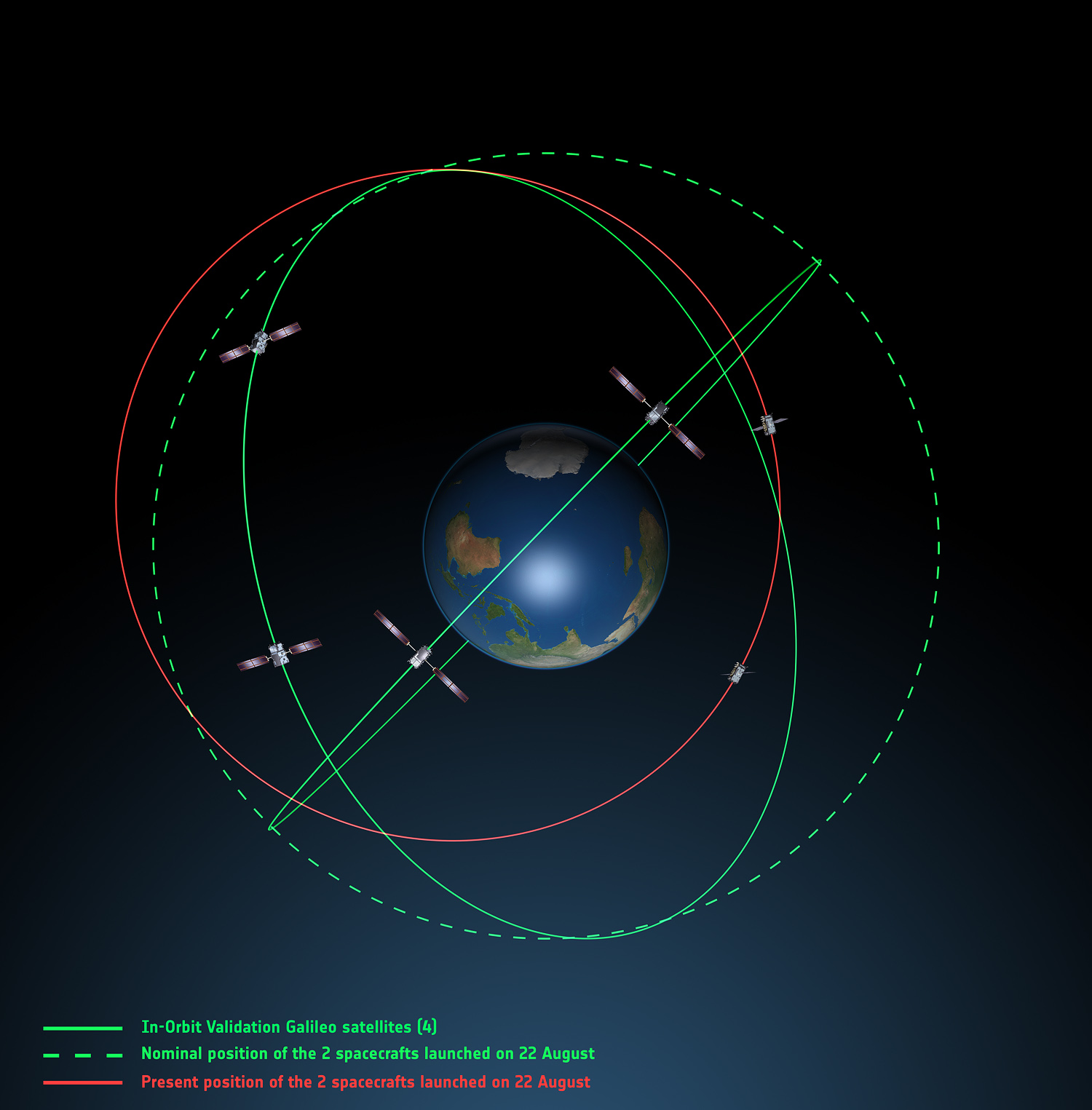
Galileo orbits viewed from above: Orbits of the fifth and sixth satellites in red, compared to their intended position in dashed green, and the position of the four satellites launched in 2011 and 2012 in solid green. This view looks down over the South Pole to illustrate how the inclination relative to the equator is less than intended. The satellites are in an elliptical rather than circular orbit, with a maximum altitude of about 25,900 km and a minimum altitude of about 13,700 km, compared to a planned circular orbit of 23,222 km altitude. Photo: ESA
The fifth and sixth Galileo satellites have been in a safe state since August 28, under control from ESA’s center in Darmstadt, Germany, despite having been released on August 22 into lower and elliptical orbits instead of the expected circular orbits. The European Space Agency has released two diagrams showing the orbits.
ESA said that the potential of exploiting the satellites to maximum advantage, despite their unplanned injection orbits and within the limited propulsion capabilities, is being investigated. Various ESA specialists, supported by industry and France’s CNES space agency, are analyzing different scenarios that would yield maximum value for the program, and safeguard — as much as possible — the original mission objectives.
More detailed analysis, alongside consultations with industry, is under way, checking for a potential “improved orbit” where the satellites could both provide operational services.
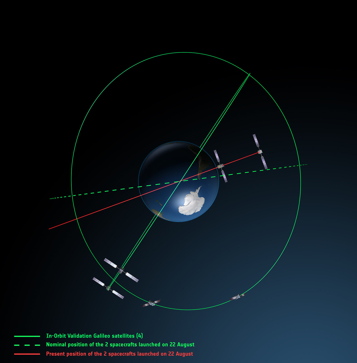
Galileo orbits viewed side-on: The fifth and sixth Galileo satellites in red, compared to their intended position in dashed green, and the position of the four satellites launched in 2011 and 2012, in solid green. This view looks side on to the two satellites’ orbital plane, which is off-center relative to Earth. The targeted orbit was circular, inclined at 55º to the equator at an altitude of 23,222 km.They are in a safe state, correctly pointing towards the Sun, properly powered and fully under control of an ESA–CNES team. Photo: ESA