The Galileo Masters competition deadline has been extended a week, until July 7. The European Satellite Navigation Competition (ESNC) is looking for services, products, and business innovations that use satellite navigation in everyday life.
“The ESNC submission database was originally scheduled to close this Monday at midnight (CET). As the ESNC has met with considerable interest and plenty of new registrations in the last couple of days, we decided to give participants one week of added time until 11:59 p.m. (CET) on Monday, 7 July 2014 at www.esnc.eu,” said Kathrin Sturm, Project Management (ESNC / Galileo Masters) Anwendungszentrum GmbH Oberpfaffenhofen.
“Don’t miss your chance to win your share of the EUR 1 million prize pool, including cash, business incubation, coaching, patent consulting, prototyping and marketing support, access to customers, and user communities. All winners will be in the running for the grand prize of EUR 20,000 and six months of incubation at a regional centre of their choice.”
Prizes will be awarded by some of the most relevant institutional GNSS stakeholders, such as the European GNSS Agency (GSA) and the European Space Agency (ESA). In addition, partner regions from all over the world are hosting regional challenges.
In 2013, 25 partner regions offered prizes, and seven special prizes were provided by leading European industry and research partners. Entries will be assessed by the expert panels of the regions and special prize partners.
The overall winner — the Galileo Master — will be selected from among all regional and special prize winners by an international panel of high-ranking experts. The Galileo Master will be revealed at an awards ceremony in Munich, Germany, in October.
Flying for GPS, a chronicle of Len Jacobson’s role in the development and promotion of the Global Positioning System, has just been published.
The book spans a 50-year career, during which Jacobson flew 2.5 million miles as a missionary for GPS and as a developer of user equipment. He kept an extensive log of all of his flights, and it enabled him to recreate in his book much of what happened with GPS during his career, and his impressions of why these events occurred.
Flying for GPS covers the user-equipment evolution from expensive, complex, and voluminous military sets to today’s low-cost chips buried in our cell phones. It traces a system designed primarily for military and civilian aircraft, ships, and land vehicles to an essential utility of everyday life, enabling new businesses, more safety, and the ability to track everything that moves. It is also a memoir written for the GPS community.
The book draws from Jacobson’s GPS experience while working for Hughes Aircraft, Magnavox, Interstate Electronics (IEC), and his own company, Global Systems and Marketing, Inc.
He worked on various assignments from most of the major GPS companies and several small businesses that were trying to find a position in the GPS market. He also participated as an expert witness in many legal cases involving GPS, from patent disputes to accident reconstruction to parolee tracking.
In parallel with the evolution of GPS, the book chronicles the changes in commercial air travel as Jacobson experienced it, from flying on a PanAm 707 in 1963 to an Air France A380 today. The book is available now from www.xlibris.com, Amazon, Barnes & Noble, and soon from ebook outlets.
Len Jacobson.
Excerpt from Flying with GPS
By Len Jacobson
A man in a trench coat borrowed one of our civil GPS Z-sets in late 1979. He couldn’t or wouldn’t say what it would be used for. He suggested that I call over to the Joint Program Office (JPO), and they would verify the validity of the request. A year later I found out what it was all about.
The Z-set had two boxes, a receiver and a panel mounted control/display unit (CDU). We got the receiver back but we never got the CDU. I learned later that the Z-set had been installed in one of the helicopters used in operation Eagle Claw, the failed April 1980 raid to rescue the U.S. Embassy hostages in Iran. I guess the Special Forces were able to recover the Z-set receiver but not the CDU, as the helicopters were all destroyed.
I ran a coverage plot for the day of the raid over Iran, and found four satellites were in view at that time. I also received a copy of an Iranian newspaper that had a big article on GPS in Farsi. I couldn’t read it and I don’t think it mentioned the raid, but there was a diagram of the GPS constellation, so I know the Iranians were very aware of GPS. That mission may have been the very first operational military use of GPS.
Another Covert Role. In September of that same year, a Vela reconnaissance satellite detected a “double flash” that was deemed by many to be evidence of a atmospheric nuclear explosion off of South Africa in the South India Ocean. While many of the details are classified, there is quite a write up about it in Wikipedia, under “Vela Incident.”
This came at a time when the GPS program was in even greater budget peril than normal. The Secretary of the Air Force at that time was trying to zero out the GPS budget, and it looked very likely he would succeed. But along came a procurement for a Nuclear Detonation Detection System payload package to be placed on all future GPS satellites. I believe that saved the GPS program from a premature demise.
I also suspect, as do many others, but cannot prove, that the flash was created by an Israeli nuclear test. If so, one might infer that Israel actually, albeit unwittingly, saved the GPS program from extinction.
Len Jacobson is a retired GPS consultant, having worked in the field since 1968. He is a charter member of the Editorial Advisory Board of GPS World magazine and is also still active in the Institute of Navigation, for which he served as western regional vice president twice and held leadership roles in several of its conferences. He lives in Long Beach, California. Visit his site at www.lenjacobson.com.
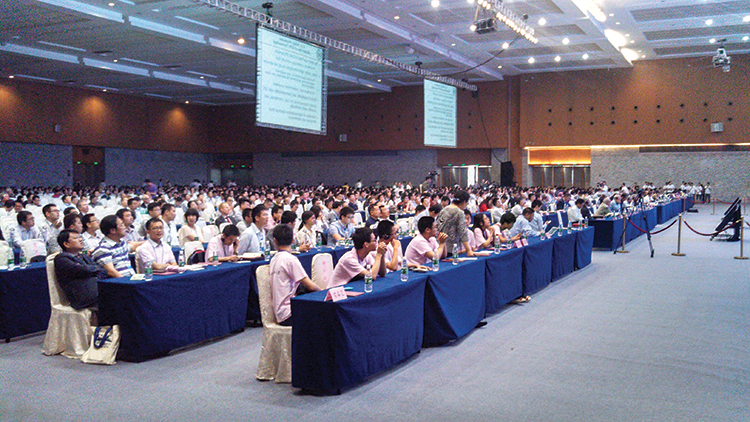
I attended the China Satellite Navigation Conference in Nanjing in May, the fifth year of CSNC and my third time attending. Tremendous progress was evident this year in terms of BeiDou (BDS) deployment and China’s general openness and willingness to collaborate over those years. I have also seen a slowly growing international presence at the show and expect that to continue to increase as well. You may recall my column last year about Little Tigers. Well, they aren’t so little any more. As for the tycoons, you will have to read to the end.
The conference opened with the usual provider updates. Chenqi Ran, who runs the China Satellite Navigation Office, the lead government agency for BDS, started off. It’s always good to hear his update delivered in China, where the is a little more freedom to provide information beyond the standard pitch. China continues on pace to its plan for the third step of BDS with five geosynchronous-orbit, three inclined geosynchronous-orbit, and 27 mid-Earth orbit satellites for a worldwide system by 2020. They are meeting their stated goal of 10-meter accuracy regionally today, and as good as 5-meter near the Equator. Ran also provided interesting numbers for the fast-growing Chinese domestic market:
More than 2 million BDS chips sold in China in Q1
More than 300,000 vehicles equipped with BDS
20 domestic brands offering car navigation systems
First consumer tablet (Samsung Galaxy Note 3) with BDS.
First consumer smartphone (Huawei B199) with BDS
The updates from other providers (GPS, GLONASS, and Galileo) were relatively standard and did not contain much new information. I had hoped that maybe the Russian presentation would provide more information about the April outages, but nothing was forthcoming and I was not overly surprised.
The conference itself is very well organized and runs nine parallel technical tracks over two full days, with additional special-interest sessions. All of the presentations are in Chinese, however the conference provides headsets for simultaneous translation, and many presenters have dual slide sets in Chinese and English, so it is easy to attend anything that seems interesting.
I came as an invited speaker on the Institute of Navigation (ION) panel organized by Professor Jade Morton from Miami University, Ohio, and Professor Lu of the National Timing Service Center near Xian. The ION panel was well attended and included a short panel discussion at the end.
One of the most interesting outcomes was that both Broadcom and Trimble showed approximately 25 percent accuracy improvement by adding Beidou to their existing GPS/GLONASS solutions. It was interesting not just because they reached the same number, but because Broadcomm was talking in meters about urban-canyon performance and Trimble was talking in centimeters about precise positioning.
It became clear that everyone sees BDS as an important part of their roadmap at L1, regardless of how many frequencies they currently support. I must also note that both Professor Morton and Professor Lu were outstanding hosts and showed us some of the wonderful local sites.
Exhibit Hall
The biggest change from last year was in the exhibit hall. I would estimate the overall floor space grew by 50 percent, with 106 companies in specially designed booths (up from 56 last year) and another 44 in standard booths.
The content change was even more dramatic. Last year there were a lot of small booths with pretty basic displays, mostly of prototypes and slideshows. This year, there were many more extremely large booths that were very professionally created. They had evolved into displaying very polished-looking finished products with nicely edited videos. It was clear that this was all targeted at domestic buyers, as it was difficult to find anyone on the show floor who spoke English (except in the Spirent booth). These are no longer little tigers. These are now real companies, out hunting for new business.
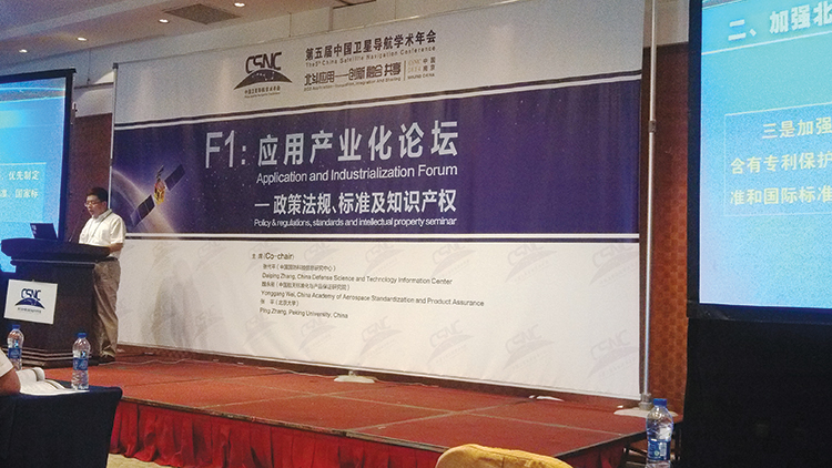
Policy and Intellectual Property
My other favorite topic to listen to at this conference is on policy and intellectual property (IP). That is where I spent most of my time and was not disappointed. There was in fact an entire session dedicated to intellectual property, and several presentations on the global state of affairs of patents in GNSS.
Interestingly, most of the speakers were either lawyers or from government, but there were some corporate ones as well. Several speakers highlighted the recent disagreement and settlement of the patent dispute between the United States and the United Kingdom over complex modulation patents. There was a large element of underlying concern that although the U.S. had been able to settle the dispute, it might be very hard for China if either the U.S. or the UK came after them. They had several charts showing how far behind they were in GNSS patents, in an effort to encourage local companies to create more IP and patent it. They also showed they have made significant progress in recent years in domestic Chinese patents, though they still have a long way to go in international patents.
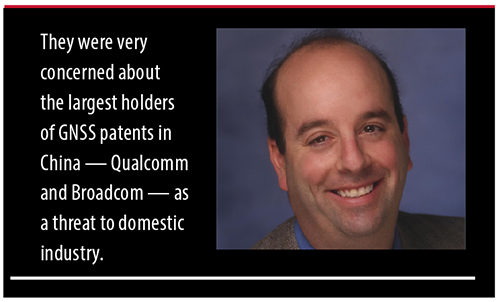
They were also very concerned about the largest holders of GNSS patents in China — Qualcomm and Broadcom — as a threat to domestic industry. They cited the GlobalLocate/Broadcom versus SiRF/CSR lawsuit as a cautionary tale. Several presenters showed the dominance of Broadcomm and Qualcomm in terms of domestic Chinese patent holdings and referred to them as the “Tycoons.” I envisioned Rich Uncle Moneybags, the guy from the Monopoly game wearing the top hat, walking around with patents instead of dollar bills hanging out of his hat.
Conclusion
The little tigers have definitely grown up. They are much bigger, have real teeth, and are definitely trying to stake out territory in the fast-growing domestic market. But the Tycoons still have the upper hand in the mass-market battle for consumer devices. For the moment, anyway.
The Tycoons are going to have to start spending some of their bounty in China if they want to maintain that market share against rapidly evolving domestic competition. I won’t be surprised if next year we see the Tycoons exhibiting at CSNC, and soon after that, the tigers looking to expand their hunting ground into nearby markets in Korea, India, and Japan.
Greg Turetzky is a principal engineer at Intel responsible for strategic business development in Intel’s Wireless Communication Group focusing on location. He has more than 25 years of experience in the GNSS industry at JHU-APL, Stanford Telecom, Trimble, SiRF, and CSR. He is a member of GPS World’s Editorial Advisory Board.
The statements, views, and opinions presented in this article are those of the author and are not endorsed by, nor do they necessarily reflect, the opinions of the author’s present and/or former employers or any other organization the author may be associated with.
Berg Insight estimates that revenues for remote patient monitoring (RPM) solutions reached € 4.3 billion in 2013, including revenues from medical monitoring devices, mHealth connectivity solutions, care delivery software platforms and monitoring services. RPM revenues are expected to grow at a CAGR of 35.0 percent between 2013 and 2018, reaching € 19.4 billion at the end of the forecast period.
The findings are discussed in the report “mHealth and Home Monitoring” (PDF brochure).
Savings attributable to payers and care providers will by far exceed this amount as connected care solutions can allow better health outcomes to be achieved more cost efficiently. The new care models enabled by these technologies are furthermore often consistent with patients’ preferences of living more healthy, active and independent lives.
While the healthcare industry is advancing towards an age where connected care solutions will be part of standard practices, this progress is still far from uniform. “The growth in the remote patient monitoring market is today centred on very specific market verticals and regions. Most of the market growth in the sleep therapy segment has for instance occurred in the US and France, where frequent compliance audits are becoming more common,” said Lars Kurkinen, Senior Analyst, Berg Insight.
He added that the telehealth market benefits from local and regional project financing in several European countries, whereas remotely monitored medication dispensers gain traction among home care providers in the Benelux and Nordic countries in particular.
In addition to this, the first pharmaceutical companies have recently initiated rollouts of connected adherence monitoring solutions that are bundled together with specific drugs. “Another high-level development that will have a major impact on the use of connected care solutions in several countries during the coming years is the shift from fee-for-service reimbursement systems to pay-for-performance structures that emphasize cost-effective delivery of quality care,” said Mr Kurkinen. In the U.S., one example of this development is the large number of RFPs for telehealth solutions that are being issued due to the hospital readmission reduction programs.
Also, registration is now open for the 54th Meeting of the Civil GPS Service Interface Committee (CGSIC), to be held September 8-9, 2014, at the Tampa Convention Center in Tampa, Florida, in conjunction with the Institute of Navigation’s Global Navigation Satellite System conference (ION GNSS 2014).
All CGSIC meetings are free and open at no charge to the public, but attendees pay their own travel, hotel and meal expenses. At the ION link, select “Register Online.” Once you create an ION account, necessary to gather information for badging, choose “I am Registering Myself.” Choose “Registration Type” from the blue banner across the top and then scroll down to the bottom of the next page to “View Other Options.” At the bottom of the next page you will find “Select” for “CGSIC Only” and then complete the registration. If you are registering and paying to attend the ION Conference, CGSIC registration will be included and nothing else is required.
The meeting will contain important updates from GPS program officials and give attendees an opportunity to learn about the broad array of GPS-based applications that are available, according to Rick Hamilton, CGSIC Executive Secretariat.
The draft agenda can be seen on the GPS.gov website. If you have any new suggestions for the agenda, would like to present a topic, or if you found certain information in past meetings useful and would like to hear more, contact the Navigation Center. Please be sure to select “Civil GPS Service Interface Committee (CGSIC)” from the pull-down menu. Or, send comments directly to the Executive Secretariat by e-mail at [email protected].
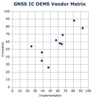
ABI Research’s 2014 GNSS IC vendor matrix names Qualcomm as the leading GPS integrated circuit (IC) vendor, followed by Broadcom in second place. For the first time, MediaTek achieves a top three finish after another year of strong growth and robust shipments as a result of its targeted design strategy, ABI Research revealed in its “GNSS IC OEMs” report.
The vendor matrix compares companies on 17 criteria across the broader categories of GNSS Innovation and Implementation. Qualcomm remains the dominant player with a strong ubiquitous location platform in IZat — this will be vital for success in high volume cellular handsets in 2015. It is also in a strong position to grow in other GNSS markets.
Broadcom continues to compete aggressively through innovation, receiving the highest score for this category for yet another year. Already in 2014, Broadcom has announced its concurrent tri-band BCM 47531 IC and the BCM 4771 GNSS SoC designed for wearables, featuring a sensor hub and always-on capabilities. Finally, it has also announced its 5G Wi-Fi SoC, which supports its new proprietary FTM-based AccuLocate technology.
u-blox has also moved up a position to fourth in this year’s assessment. It continues to grow revenue year-on-year, with little to suggest this will change in the coming year. It is also the first time u-blox has finished ahead of CSR, which was ranked fifth. CSR continues to transition and faces another arduous year in 2014. It will be 2015/16 when the effects of these tough decisions are proven out to be correct or not.
MediaTek has now emerged as a major threat, taking third on innovation and 2012 market share rankings, following very impressive shipments of its combo ICs into local Chinese smartphone manufacturers. It is also strong on PNDs/recreational and cameras, with a growing presence in other markets. Its move to fully embedded GPS in 2013 should prove significant in driving market share in the future.
Beyond this, STMicroelectronics also deserves a mention with its new Teseo III platform giving it significant design flexibility allowing it to compete aggressively in existing markets while expanding into new opportunities.
LocationSmart, a provider of cloud-based location and interactivity services, has announced the issuance of US Patent 8,666,373 by the U.S. Patent Office for location reporting based on the dynamic status of a user. The patent covers a system and method of determining location for the user, including dynamically determining a status of the user and allowing acquisition of the user’s location based on the determined status.
The issued patent enhances LocationSmart’s cloud-based, cross-carrier location and interactivity platform that is powering the enterprise with location insights through a comprehensive set of web services application programming interfaces (APIs), the company said.
This patent further covers the location reporting of a person based on a dynamically monitored status; for example, when an employee is on the job versus when the employee is on his or her own time. Reporting is responsive to the received location tracking request, based on current status and allowed permissions. This is significantly instrumental for monitoring and managing mobile workforces, LocationSmart said.
“Knowledge of when to obtain location information based on dynamically changing status is fundamental to several of our key verticals,” said Mario Proietti, CEO of LocationSmart. “This patent strengthens the protection and rendering of our services for mobile check-ins and status reporting in the workforce management and transportation sectors.”
The LocationSmart platform is employed by leading companies in a number of industries, enabling a multitude of applications including service assistance, proximity marketing, workforce check-ins, emergency alerting, mobile gaming and transaction verification.
Potential GNSS Back-up Improves to GPS-Level Accuracy
A new enhanced differential Loran system demonstrates 5-meter accuracy not achievable by the current DLoran system, and requires less expensive reference stations. A prototype tested in Rotterdam’s Europort area uses standard mobile telecom networks and the Internet to reduce correction data latency — a key source of error — by one to two orders of magnitude.
By Durk van Willigen, René Kellenbach, Cees Dekker, and Wim van Buuren
For maritime applications, Loran is considered as the most promising backup for GNSS for situations where the use of navigation satellite signals is denied. For this reason, the Dutch Pilots’ Corporation askedReelektronika to investigate whether differential Loran could meet the Dutch Pilots’ 5-meter accuracy requirement for a harbor navigation system. This proved to be an enormous challenge, as preliminary tests showed that even 10 meters was difficult to achieve with differential Loran (DLoran) as promoted by Trinity House, the UK lighthouse authority. This led to a thorough renewed investigation of all possible error sources of a complete differential Loran system. The outcome of this research is very promising, as a couple of major error sources could be isolated. This made the complete system better understandable, so adequate countermeasures could be taken.
Loran History
The development of Loran-C started in the United States about fifty years ago. It is a terrestrial low-frequency (100 kHz) system organized as chains, each consisting of a master station with two or more secondary stations. Each station broadcasts in a strict time format series of 8 or 9 pulses of approximately 250 µs. The effective radiated power is in the range of 100 to 1,000 kW, depending on the required working range. These high powers are required by the high levels of atmospheric noise in the 100 kHz frequency band.
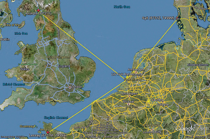
Figure 1 shows the test area of enhanced Differential Loran (eDLoran), using the Loran stations of Lessay (France), Sylt (Germany), and Anthorn (UK).
Figure 1. The Loran configuration in the test area of Europort.
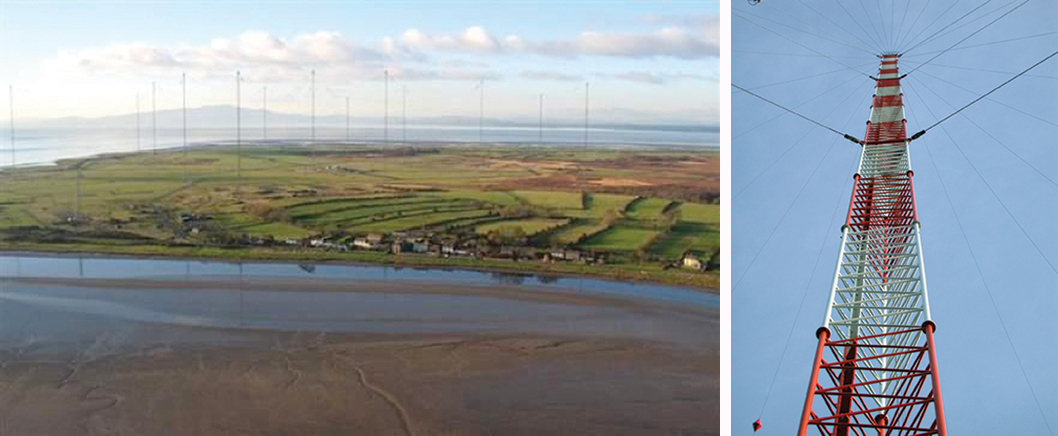
Radiating such high-power pulses requires large vertical transmitting antennae of about 200 meters height (Figure 2). These high power levels have long been seen as a drawback of Loran-C. However, the upcoming GNSS interference risks changed this apparent drawback into an advantage, as jamming such high field strengths is hardly achievable unnoticed. Loran-C is, unfortunately, less accurate than GNSS but it is nearly impossible to jam over large areas. This is one of the major reasons that Loran gets so much renewed interest by all who face risks in life-critical and environment-critical applications of radio navigation.
Figure 2. Left, the antenna park of 13 masts of ≈200 meters at Anthorn, UK. Right, the 200-meter mast at Sylt, Germany.
Differential Loran
Standard Loran does not meet accuracy requirements for harbor entrance and approaches. The International Maritime Organization requires 10 meters (95 percent), which is at least 5 times more demanding than standard Loran can provide. So, differential techniques have been developed and implemented, which are comparable with differential GPS. Although the error sources of GPS and Loran are quite different, the major common error source in both systems is the lack of accurate propagation models.
Several years ago, the General Lighthouse Authorities (GLAs) of the UK and Ireland implemented Differential Loran (DLoran) in the test area around Harwich. DLoran is based on a Loran reference station in the area of interest which measures temporal deviations of the measured pseudoranges. These “errors” are then sent to the user receiver through the Eurofix Loran Data Channel. This technique strongly resembles that of differential GPS. Unfortunately, for a number of reasons it proved to be impossible to achieve absolute accuracies of better than 10 meters with DLoran.
This has led to a new research project to find a more accurate differential Loran technique. All possible error sources have been investigated again where possible, producing unexpected solutions regarding accuracy and cost.
Error Sources
The total position error of Loran depends on the accuracy in time of the high-power generated Loran pulses feeding the antenna, the stability of the physical phase center of the Loran transmitter antenna, stability of the tuning of the antenna circuit, the accuracy of the measured additional secondary phase factor stored in the Additional Secondary Factor (ASF)database, and the quality of the Loran receiver. ASF is the additional delay when Loran signals propagate over land with a varying conductivity. As the ASF data are not fixed but vary slightly over time, temporal de-correlation, differential techniques have been developed to counteract that effect. In standard DLoran systems, the differential corrections are sent to the user through the Eurofix data link. Particular error sources include:
Transmitter Timing Accuracy. A Loran transmitter sends about 100 pulses per second. Each station has three cesium clocks time-synchronized to Coordinated Universal Time (UTC) via a time-transfer network. A two-way satellite time-transfer system will make it simpler and more accurate.
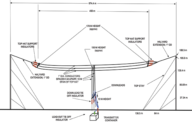
Antenna Phase-Center Stability. Loran transmitter antennas are vertical towers approximately 200 meters high to provide vertical polarization. Its phase center, at the published position, does not move more than about 1 meter according to the station crew at Sylt.
This situation is very different for a wire antenna as installed at the station at Anthorn in Northern England. The top-loaded wire antenna is installed between two towers 200 meters tall and separated by 675 meters (Figure 3). In stormy weather, the antenna position is not stable and does not continuously coincide within 1 meter of the published position of the antenna.
Figure 3. The enormous top-loaded Loran wire antenna at Anthorn. This type of antenna is not rigidly stable during storm. By courtesy of Babcock International Group.
ASF Data. The net travel time of the Loran signal from the transmitter to the receiver antenna is the sum of the propagation through the atmosphere (primary factor or PF), some extra delay due to traveling over seawater (secondary factor or SF), and finally ASF. The PF and SF are calculated from models, while the ASF must be measured. These calculations can only be accurate if the net travel time can be accurately determined and the distance between transmitter and receiver can be calculated with the help of GPS-RTK. The time stamps of the signal when leaving the antenna are not sufficiently accurate. The time stamps on the received signals are established by using a GPS-disciplined rubidium (Rb) clock. In conclusion, we cannot accurately measure and compute the absolute ASF values. All mentioned possible errors led to the use of differential techniques.
Differential Loran
As it is not possible to measure ASF data to sufficient accuracy, time-stamp errors at the transmitter can be circumvented by applying differential techniques over a limited area of interest. The receiver at the reference site and the rover receiver experience the same transmitter timing error, which makes it a common error and harmless in differential Loran. It is more difficult to cope with the offset of the Rb clocks at the reference and the rover sites, which is, unfortunately, not common-mode. Differential clock errors of a moving rover receiver may easily rise to 20 ns, equivalent to 6 meters. This type of error limits the achievable accuracy of an ASF data base.
The measured/calculated ASF data are due to weather effects on propagation slightly moving with time. That is the reason to use a reference receiver to measure these temporal variations and send these as AFS corrections to the rover receiver via the 30 bps Eurofix data link. Unfortunately, this rather slow data link introduces significant data latency, which turned out to be the source of significant differential Loran errors.
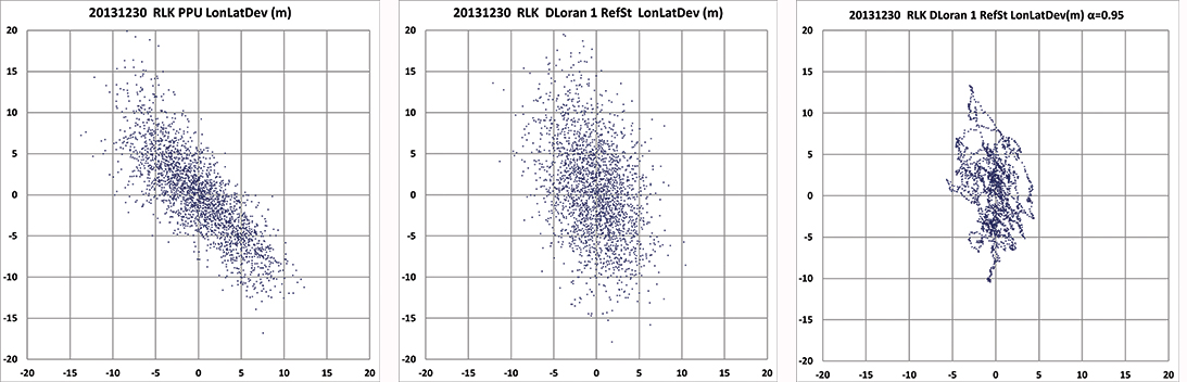
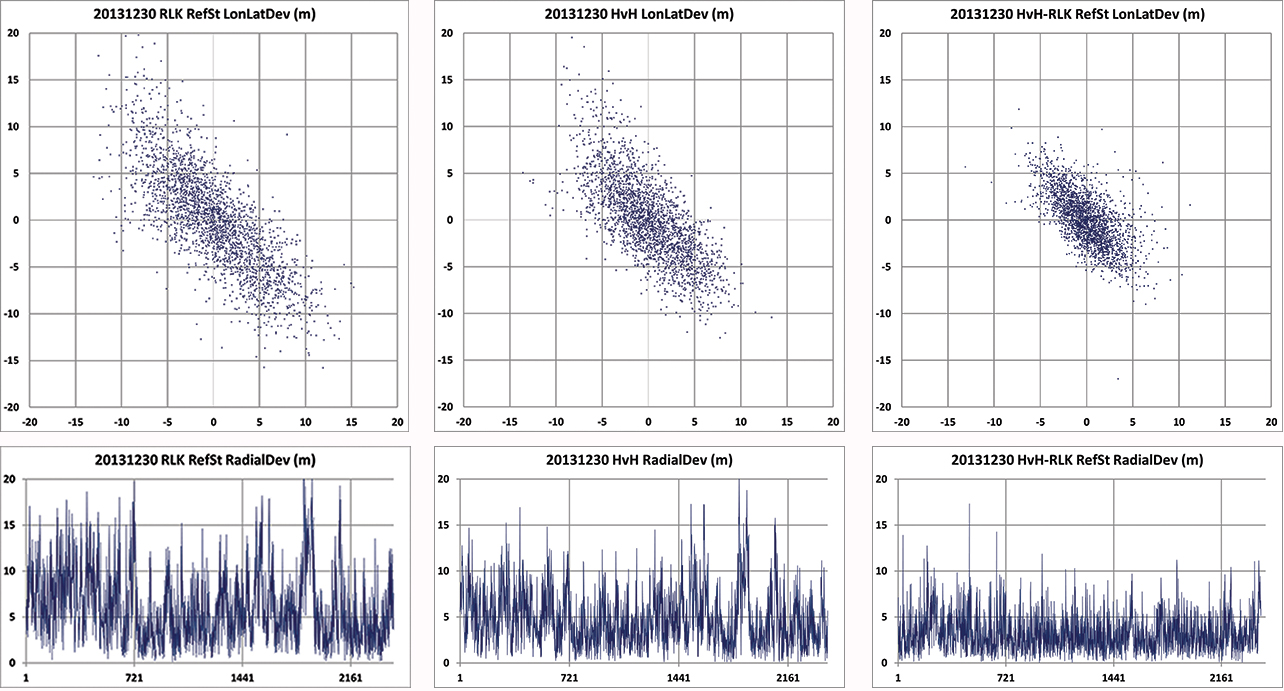
In the UK, many tests have been conducted to measure these ASF shifts and use the Eurofix data link for sending correction data to the user receiver. DLoran data are sent as pseudorange corrections per station. A complete set of DLoran correction data takes about 90 seconds. The UK plans to send correction data from multiple reference stations via a single Eurofix channel. The resulting very large data latency will preclude accuracies any better than 10 meters. The main reason of this conclusion was found by further analysis of measurements of the position of the rover receiver. These positions are shown as a scatter plot in Figure 4.
Figure 4. On the left the position deviation scatter plot at the rover receiver. The middle plot is the result after applying DLoran corrections from a reference station. The right plot of the same DLoran plot after being low-pass filtered indicating the slow moving of the phase center of the Anthorn transmitter. The axes are in meters.
The left-hand plot gives the position deviation of 2,500 independent measurements, where the scattering was thought to be caused by noise on the measurements. The middle plot is the result after being corrected by DLoran data with a 90-second data latency, which shows a somewhat modified form but still quite noisy plot. However, when the DLoran data were low-pass filtered, it appeared that often all separate measurements more or less formed lines, which would not happen with just atmospheric noise. Further, the scattering after filtering did not decrease much, which would happen if the disturbances were due to noise. See the right-hand plot in Figure 4.
This demonstrates that the source of the problem is the slow data rate through the Eurofix channel, in combination with the movements of the phase center of the transmitter antenna at Anthorn. Apparently, the solution had to be found in a much faster data link which could neither be offered by Eurofix (30 bps) nor by the U.S.-proposed OFDM technique with a data rate of approximately 1 kb/s. This unexpected result forced us to drastically change the concept of differential Loran to get much better accuracy results, as requested by the Rotterdam pilots.
Enhanced Differential Loran
The above mentioned difficulties with DLoran have led to a new concept of differential Loran which had to fulfil three important primary improvements. The first is a significant reduction in the latency of the data in the data channel; the second is that a large number of reference stations should be allowed to send correction data to the user without saturating the data channel. Finally, it is necessary to measure ASF data more accurately without being dependent on atomic clocks.
The simple conclusion was that Eurofix could not meet the first two improvements. As Eurofix is an invention of Delft University in the Netherlands, it was somewhat painful for the Dutch to admit that a much faster data link is absolutely needed to achieve a two-fold better differential Loran position accuracy. However, Eurofix is still the prime GNSS backup candidate for distributing accurate UTC over very large parts of Europe. Further, Eurofix has the capability to send short messages, which might be encrypted for secure communication purposes that might then form a terrestrial backup for Galileo PRS.
Finally, the third improvement to generate more accurate ASF data cannot be found on a pseudorange method but has to be established on position bases.
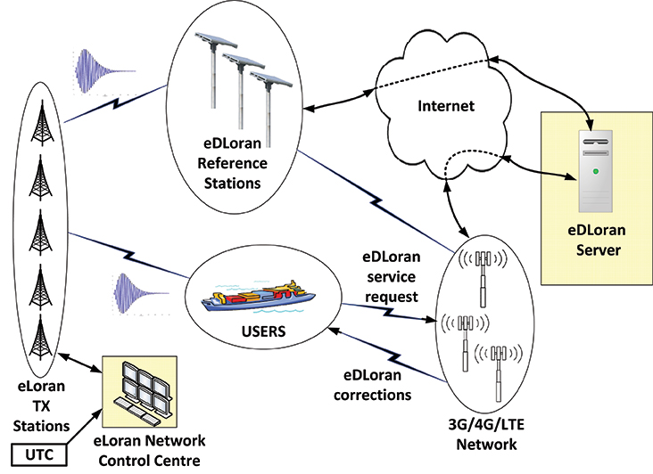
Instead of using the Eurofix channel, eDLoran uses the public Global System for Mobile (GSM) network to send the differential corrections to users. eDLoran receivers therefore contain a simple modem for connection to the GSM network. The eDLoran reference stations are also connected to the Internet, which may be implemented via a cabled access or also via a GSM modem.
Fortunately, today many GSM networks are robust in respect of GPS outages. The eDLoran concept is quite simple and is shown in Figure 5.
Figure 5. Concept of eDLoran. By courtesy of Babcock International Group.
The eDLoran infrastructure is not connected with any Loran transmitter station and operates completely autonomously. An eDLoran reference station is connected to a central eDLoran server by its connection to the Internet.
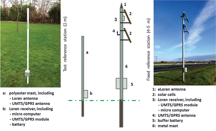
The measured positions of these reference receivers are processed in the eDLoran server, which returns the resulting correction data to the user, also via the Internet. Data latency will be not more than 2 seconds. The rover receiver starts the entire process by sending the raw position to the server, which will then return the optimal ASF database for that particular area. Corrections can be calculated by using data from multiple reference stations. Reference stations for eDLoran are small and consume not more than 10 Watts. Two types of reference stations are under development. A portable simple battery-powered version, not larger than 2 meters, can operate for 8 hours. This version is meant to do interference analysis on selected candidate locations. For a permanent installation, a continuously operating solar-powered unit is also under development. See Figure 6.
Figure 6. Concepts of a mini reference station (left) and a permanent eDLoran reference station.
It has been mentioned that measuring accurately the departure and arrival times of Loran pulses is difficult. It is however needed in order to work out the ASF data on the pseudorange measurement for each Loran station in view. Therefore, a DLoran ASF measurement receiver concept uses Rb clocks and is relatively large and power-hungry. With eDLoran, position offsets due to ASF effects are measured and an eDLoran reference server outputs position- instead of pseudorange-corrections. Measuring positions is much simpler and more accurate and can be done with standard miniature low-power eLoran receivers. No GPS-disciplined Rb clock is needed, and total costs are significantly lower. The gain in accuracy of this simpler ASF measurement receiver together with the very low data latency is one of the reasons that the resulting eDLoran position accuracy is now approximately 5 meters instead of 10 meters with DLoran.
eDLoran Results
We conducted real-life static and dynamic tests to demonstrate the capabilities of this new concept. The static tests were done in post-processing with logged data from Hook of Holland and at Reelektronika, about 40 kilometers to the east. Only standard eLoran receivers, mostly equipped with E-field antennae, were used, and no atomic clocks were applied. At Reelektronika ,we used two 2-meter mini-reference stations, while in Hook of Holland the Loran antenna was mounted on top of the 30-meter lighthouse. Dynamic tests were done on board of the MS Polaris, the new pilot-station vessel of the Dutch Pilots’ Corporation.
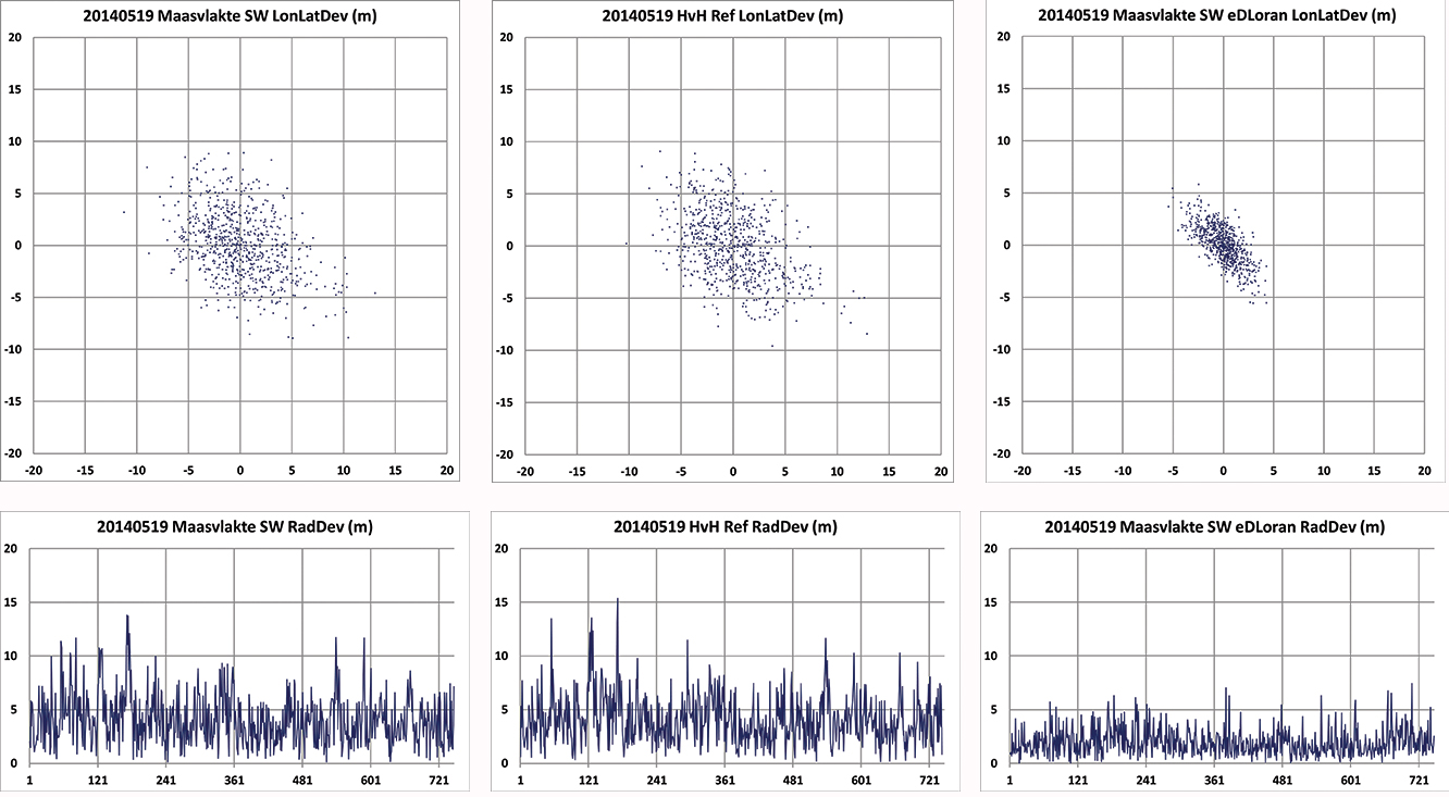
Static Tests. To give a realistic image of the resulting errors of eDLoran, the scatter plots in Figures 7 and 8 are depicted in the position domain. The radial errors are shown in the time domain where the horizontal axis gives the 5-second epochs. The left and the middle plot show the results of the rover and the reference receiver, respectively. The eDLoran plots on the right depict interesting results, as those variations in ASF are largely cancelled while the scattering is smaller than that of the measurements at the rover and the reference receiver, individually. The scattering at the two locations was apparently partly due to low-frequency disturbances, for example because of the moving phase center of the antenna at Anthorn, or instabilities in the time-control loops in the transmitters.
Figure 7. Position scatter plots in the upper row and radial error plots in the lower row of the user receiver on the Maasvlakte and the reference receiver at Hook of Holland. The right-hand column depicts the results for eDLoran. The two sites are separated by about 11 km. The horizontal axis shows the 5-second epochs.Figure 8. Position scatter plots in the upper row and radial error plots in the lower row of the receivers at Reelektronika and Hook of Holland. The right-hand column depicts the results for eDLoran. The two sites are separated by about 40 km. Some eDLoran accuracy degradation around events 250 and 500 may be due to local interference at Reelektronika.
Figure 7 shows the situation where the rover and the reference receiver were separated by 11 kilometers, while Figure 8 depicts the results when the rover receiver was at Reelektronika, more than 40 kilometers from the reference site at Hook of Holland.
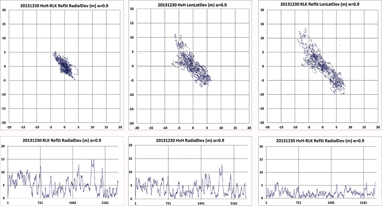
This effect of movement of the phase center of the transmitter antenna is further made visible by applying an alpha-tracker (α = 0.9) on the position data of both receivers, which have an update rate of 5 seconds. The lining-up of dots on some parts of the scatter plots in Figure 9 are believed to be due to swaying of the transmitter antenna. Due to the low-pass filtering, the disturbances now contain fewer high-frequency terms.
Investigating the radial error plots of Figure 9, it is remarkable that the large excursions at event 1880 largely cancelled. The disturbance at event 1880 might be caused by antenna movement at Anthorn, which is nearly perfectly cancelled by eDLoran.
Figure 9. Above plots are based on the same data as in Figure 8 but now after passing through an alpha tracker with α = 0.9. Note the correlation of the radial deviations around events 1800 in both 40 km separated receivers and the strong reduction in scattering.
Investigating the radial error plots of Figure 8 and 9, it is remarkable that the large excursions around epoch 1900 largely cancel, while this is not happening at epoch 250. There, some local interference might have been the cause. The disturbance at event 1900 might be caused by swaying of the Anthorn antenna which is then a common-mode error at both receivers and is therefore strongly reduced in the eDLoran plots.
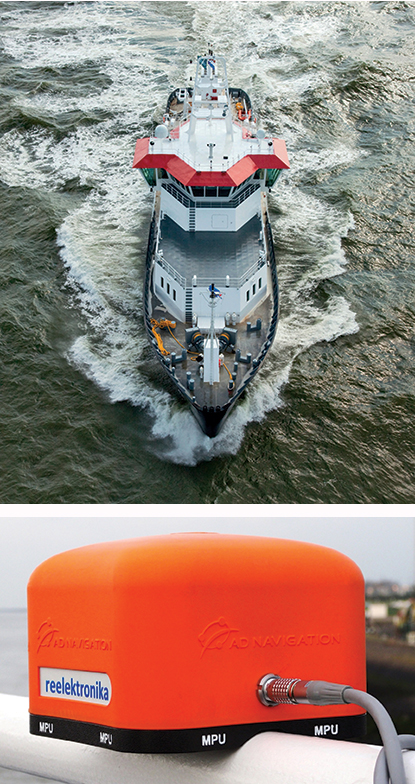
Dynamic Tests. Dynamic testing on board the Polaris at sea (Figure 10) is somewhat more complex to do correctly. The eDLoran receiver was installed about 1 meter above the GPS-RTK reference receiver. In this way, the lever-arm problem of not installing the antennae of the two receivers at the same location was avoided. The next issue was measuring ASF position data, which should happen synchronously with the GPS measurements. Time synchronization can be achieved by using simple GPS receivers at both Loran receivers. Some months later, the eDLoran concept was tested by using the stored AFS data and using a Reelektronika eDLoran receiver as a portable pilot unit (PPU) which looks identical to the GPS-based units the Rotterdam pilots use, manufactured by AD Navigation in Norway.
Figure 10. Top right, the Pilot Station Vessel MS Polaris (80 meters) used to test eDLoran (photo copyright Loodswezen). Below is a complete eDLoran receiver with a ‘life-line’ connected to avoid losing the receiver by accident and to allow charging the internal batteries.Figure 11. Five test antennae on the MS Polaris. From left to right the ADNav Master Processing Unit, the ADNav Heading Unit, the ADNav Position Unit with the Reelektronika eDLoran receiver 1 meter above it and, finally, a second Reelektronika eDLoran receiver.
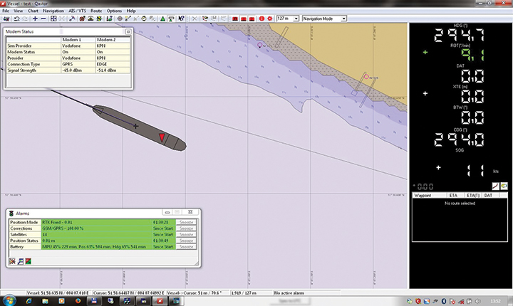
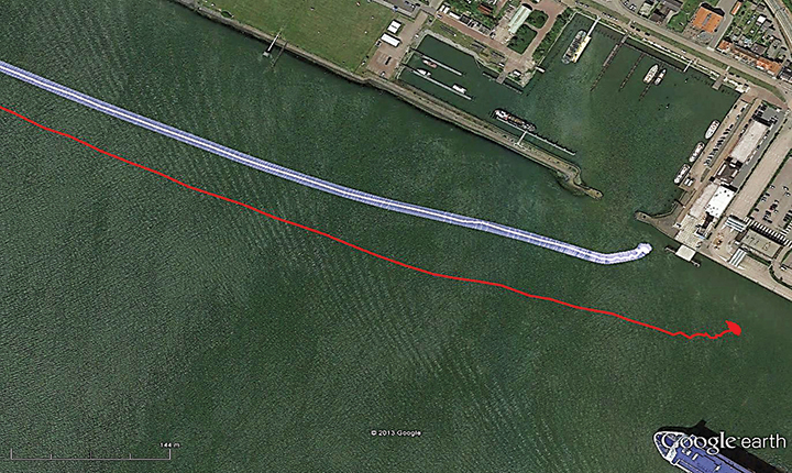
The results have been demonstrated to the harbor authorities in real-time on the laptop of the pilots on which the GPS-RTK and the eDLoran position were simultaneously shown. See Figure 12, where the large gray ship model represents the position and heading derived from GPS-RTK. The width of the ship model is 10 meters. The red triangle gives the eDLoran position; it remains within the borders of the ship symbol. For further demonstration purposes, the logged GPS-RTK data could also be plotted on a Google Earth map (Figure 13). The track was widened to 10 meters, as the accuracy requirements are 5 meters on either side of the track. The raw eLoran track is also shown, as well as the final white eDLoran track of unfiltered raw eDLoran data, which stays well within the 5-meter boundaries.
Figure 12. The large ship symbol (grey) is derived from the GPS-RTK receiver of the Rotterdam pilots. The width of the ship symbol is 10 meters and the speed-over-ground was 11 kts. The red triangle is generated by the eDLoran receiver and remains between the required ± 5 meter limits for eDLoran.Figure 13. The red track is based on raw eLoran data without any corrections. The transparent blue line is made by GPS-RTK and is widened to 10 meters giving the required ± 5 meter limits of eDLoran. The white line is output from the eDLoran receiver which stays within the borders of the 10 meter wide transparent blue line.
During the sea trials, the eDLoran receiver was connected to the eDLoran server on land via a miniature GSM modem to the Internet. All differential data were read via this mobile link. The required data bandwidth is very low, approximately 150 bps per ship (client).
Conclusions
The outcome of this research opens some new and quite surprising possibilities for multiple applications:
eDLoran offers the best possible eLoran accuracy, as it does not suffer from unstable transmitter antennas, sub-optimal timing control of the transmitter station, and differential data latency.
There is no need to replace older Loran-C stations with eLoran transmitters; this potentially would save large amounts of money. Further savings may be obtained by containerizing the transmitter and operating the stations unmanned.
Installing eDLoran reference stations is fast, simple, and very cost-effective.
The Eurofix Loran Data Channel can be freed from a relatively large stream of DLoran data, which leaves the full data bandwidth available for UTC and short-message services over very large areas.
As there is no data channel bandwidth limitation, multiple reference stations can be installed, offering increased reliability and making the system more robust to terrorism and lightning damage.
Single or multiple eDLoran servers can be installed in a protected area. There is hardly a practical limit to the number of differential reference stations to serve.
The server selects the most optimal differential data based on the raw position of the user (client) and the available reference stations.
As there is no need for any Loran data channel, eDLoran can be installed in all locations where Loran or Chayka coverage and access to the Internet are available. Required data bandwidth is approximately 150 bps per user.
Standard eLoran receivers used on controlled trajectories (for example, pilots and ferries) collect position data when accurate DGNSS is available. The collected GNSS and eLoran data can be uploaded to the server to further refine the ASF data base. It is basically a self-learning system.
All eDLoran reference stations monitor the eLoran and GNSS positions to offer alarm services in case of GNSS jamming or spoofing.
Acknowledgments We are very grateful for the near-endless hospitality of the Rotterdam Pilots and especially the crew of the MS Polaris and the MS Markab. Without their help, we would not have obtained the eDLoran results presented here. During the days at sea, we learned how much experience and professionalism is needed to bring those extremely large vessels safely in the harbor of Rotterdam.
We thank Martin Rumens and Dave Kelleher of Babcock International Group for their valued comments and diagrams.
DURK VAN WILLIGEN is a retired professor of electronic systems for navigation at the Delft University of Technology. He is founder and president of Reelektronika B.V., and started the development of Eurofix in 1985. He received the Thurlow Navigation Award of the Institute of Navigation (U.S.) and the Gold Medal of the Royal Institute of Navigation (UK).
RENÉ KELLENBACH graduated from Delft University of Technology in electrical engineering. After joining Reelektronika as a systems engineer, he has been involved in designing hardware and software for radionavigation and radar systems.
CEES DEKKER graduated from the Delft University of Technology in electrical engineering. He worked previously at Philips Research Labs and now assists Reelektronika B.V. with the development of Loran systems and GPS-related projects, and information systems.
WIM VAN BUUREN is a licensed maritime pilot in Rotterdam who took the initiative to develop a backup positioning system for the approaches to Rotterdam. He has been involved in the design and development of the hardware and software of Portable Pilot Units on a national and European level since 2000.
Juniper Systems and Futura Systems have partnered to provide enterprise utility GIS solutions for the electric and utilities industries. This August, Futura Systems will be launching at its user conference a new pole-staking application called GPSStaker.
Staking, or line design, is performed when new locations need to be added to an existing electric line. It involves mapping a new utility pole run, ensuring that the distance between each pole is up to code and geolocated, and then recording the GPS coordinates of where each pole should be placed. GPSStaker was optimized for Juniper Systems’ Archer 2 rugged handheld, and works with Esri ArcMap.
Using GPSStaker, stakers — or field engineers — can GPS-stake a job on the Archer 2 using ArcPad 10. The data is then automatically synced back into a main database.
“The people in the field want lighter hardware and more efficient staking processes,” said Doug Malinowski, CIO of Futura Systems. “With Futura GPSStaker and the Archer 2, we’ve designed a promising solution that combines the accuracy they need with the design quality they want.”
Registration is open for Trimble’s International User Conference, Trimble Dimensions, being held November 3-5 at the Mirage and the Treasure Island Hotels in Las Vegas. The conference addresses innovations in agriculture, construction, civil infrastructure, engineering, government, mapping, natural resources, surveying, telecommunications, transportation, logistics and utilities.
Trimble Dimensions provides insight into how information technology can transform the way professionals work by using integrated workflows to increase productivity, the company said. Participants can hear how industry colleagues use Trimble’s end-to-end technology to transform data into intelligent, usable information. Attendees will see first-hand how new tools, processes and ideas can help make a positive impact on their business.
Throughout the conference, attendees will have a variety of opportunities to network with key industry players, nurture existing business relationships, build partnerships, and discover how to overcome challenges in today’s competitive business environment.
Highlights include more than 400 educational sessions, including both on-site and off-site immersive training, more than 30 specialized tracks to advance career objectives with many sessions qualifying for Professional Development Hour (PDH) hours, and on-site product demonstrations.
Google enhanced its online mapping service by acquiring Mountain View, California-based Skybox Imaging for $500 million in cash. Sources say both Google and Facebook are purchasing satellite and drone companies in an attempt to expand into other market areas.
One of the ways Google will be leveraging Skybox is in disaster relief and to improve Internet access in remote areas, something the company has been strongly pursuing, according to GPS World’s LBS Editor Kevin Dennehy.
On its website, the five-year-old Skybox said that it plans also to share in the development of the burgeoning autonomous vehicle market and continue to design its own satellites.
Skybox posted a message about the acquisition on its website: “We’ve built and launched the world’s smallest high-resolution imaging satellite, which collects beautiful and useful images and video every day. We have built an incredible team and empowered them to push the state-of-the-art in imaging to new heights. The time is right to join a company who can challenge us to think even bigger and bolder, and who can support us in accelerating our ambitious vision.
“Skybox and Google share more than just a zip code. We both believe in making information (especially accurate geospatial information) accessible and useful. And to do this, we’re both willing to tackle problems head on — whether it’s building cars that drive themselves or designing our own satellites from scratch.”