Nucleus of Four Now Operational: It “Works, and Works Well”
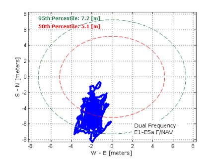
Dual-frequency Galileo positioning performance during the In-Orbit Validation phase: positioning accuracy is an average 8 m horizontal and 9 m vertical (95% of the time). Its average timing accuracy is 10 nanoseconds on average. Plot courtesy of ESA.
“IOV was required to demonstrate that the future performance that we want to meet when the system is deployed is effectively reachable,” said Sylvain Loddo, ESA’s Galileo Ground Segment manager. “It was an intermediate step with a reduced part of the system to effectively give evidence that we are on track.”
Following a March 2013 first determination of a ground location, jointly by Galileo’s space and ground segments, program managers undertook a wide variety of tests all across Europe.
“More than 10,000 kilometers were driven by test vehicles in the process of picking up signals, along with pedestrian and fixed receiver testing. Many terabytes of IOV data were gathered in all,” said Marco Falcone, ESA’s Galileo System manager.
According to ESA’s elaboration on the test results, the system has proved itself capable of solely performing positioning fixes across the planet.
Galileo’s observed dual-frequency positioning accuracy is an average of 8 meters horizontal and 9 meters vertical, 95 percent of the time. Its average timing accuracy is 10 billionths of a second. Its performance is expected to improve as more satellites are launched and ground stations come on line.
For Galileo’s search-and-rescue function — operating as part of the existing international Cospas–Sarsat programme — 77 percent of simulated distress locations can be pinpointed within 2 kilometers, and 95 percent within 5 kilometers. All alerts are detected and forwarded to the Mission Control Centre within a minute and a half, compared to a design requirement of 10 minutes.
“Europe has proven with IOV that in terms of performance we are at a par with the best international systems of navigation in the world,” said Didier Faivre, ESA director of Galileo and Navigation-related Activities.
Historically Speaking. In a February 2013 GPS World article, Peter Steigenberger, Urs Hugentobler, and Oliver Montenbruck discussed Galileo-only positioning. “Using an ionosphere-free dual-frequency linear combination of pseudorange measurements on the Galileo E1 and E5a frequencies, the position of the TUME reference station [at the Technische Universität München (TUM) in Munich, Germany] could be determined with a 3D position error of less than 1.5 meters,’” the authors said.
Crystal Ball Gazing. The next two Galileo satellites, of the full operational capability (FOC) class, currently complete their testing for flight clearance at ESA’s ESTEC facility.
Six such satellites are destined to rise into space in 2014, according to ESA’s master plan. Should all those launches occur as scheduled, Galileo’s initial services could start by the end of the year.
GNSS Vulnerable: What to Do?
Too Much Sensitivity, Not Enough Robustness, Says Parkinson
Brad Parkinson, the founding architect of GPS, told a UK conference that the system needs to be made more robust to ensure worldwide availability of services to users. His concerns over GPS availability relate to threats such as the loss of authorized frequency spectrum (implicitly creating licensed jammers), space weather due to hyperactive ionospheric conditions, and deliberate or inadvertent jamming of GPS signals.
He warned that GPS is more vulnerable to sabotage or disruption than ever before, and charged that politicians and security chiefs are ignoring the risk. Western governments are “in their infancy in recognizing the problem,” he remarked further in an interview with London’s Financial Times. “[In the United States] I don’t know anyone that is really in charge of it. The Department of Homeland Security should be [but] … they don’t have any people that understand it very well. They’ve got one person without any budget to speak of.”
He also warned that Europe’s €5 billion Galileo system is equally at risk.
Parkinson proposed a three-stage program to:
Protect (legally) the signal and physically eliminate jamming sources;
Toughen the GPS/Galileo receiver’s resistance to interference;
Augment the GPS signals with other satellites or with ground-based transmitters such as eLoran.
To support his proposal, Parkinson stated, “The number one need for all GPS or Galileo users is availability. Over the years, manufacturers of signal receiver technologies have focused too much on sensitivity and not enough on resilience or robustness. The maritime industry is a particular concern where users have taken GPS for granted. They must increase preparedness and backups as they do in aviation or other GNSS-using industries.
“Even today, most ships have only GPS and the vision of their crew to guide them when approaching harbors. As you can see from today’s conference, there are a wealth of solutions to toughen and back up GPS, many of which are not technologically difficult nor expensive, but still their adoption in sectors such as global shipping is certainly not adequate.”
As part of his protection program, Parkinson urged that penalties for jamming GPS networks be coordinated worldwide. “In Australia, if you cause interference likely to cause prejudice to the safe conduct of a vessel, it’s five years in the jug [jail] and $850,000.” Contrasting this with a U.S. case that may simply impose a forfeiture of the culprit’s jamming device, Parkinson added, “I’m calling for the community of nations to move to the Aussie-type penalties.”
In the toughening regard, Parkinson alluded to integration of GPS data with information derived from an inertial positioning system. “If you combine all of these things, a good set should be able to fly within 1 kilometer of a jammer with a 10-kilometer range,” said Parkinson. “That’s what I call toughening.”
Parkinson made his remarks as the keynote speech at GNSS Vulnerabilities and Resilient PNT 2014, hosted by the Royal Institute of Navigation. He will also deliver the keynote address, “Assured PNT: Assured World Economic Benefits,” for the European Navigation Conference on April 15 in The Netherlands.
Russia will deploy as many as seven ground monitoring and augmentation stations for GLONASS outside its national boundaries. GLONASS/GNSS Forum Association Executive Director Vladimir Klimov stated that “It is planned to deploy about six or seven stations on foreign territories this year.” Negotiations for the stations are now taking place with foreign nations.
Currently, there are 46 GLONASS ground stations on Russian territory, eight in neighboring countries, three in Antarctica, and one in Brazil. The United States recently spurned, with some Congressional trumpeting, a Russian tender to site one of the ground stations on U.S. soil.
New Instrument in Space. In mid-February, the most recent GLONASS-M satellite traveled to the Plesetsk cosmodrome for a probable mid-March launch. GLONASS-M 54 will carry a high-accuracy thermal stabilization unit, installed on the spacecraft for testing and flight qualification. The next-generation K-class of GLONASS spacecraft will loft this device to provide increased positioning accuracy.
Five GLONASS-M craft are planned for launch in 2014, in one triple and two single launches.
The design and verification of a new class of portable wideband record-and-playback system considers the relative merits and limitations of both simulator and record/replay approaches. The authors also discuss the benefits of the different test approaches to the development and characterization of various GNSS receiver types.
By Steve Hickling and Tony Haddrell
As new GNSS systems become available, and users take receivers to ever more challenging environments, the need for repetitive and repeatable testing during development grows ever stronger. Simulators have traditionally demonstrated performance and repeatability in the laboratory environment, and this approach remains the only option for planned signals not yet broadcast from space. However, this approach is becoming more complex as the number of GNSS signals and their reception environments increase.
Another way of testing receivers is through field trials. This allows investigation of conditions difficult to simulate, such as multiple reflections and interferers. These environments, however, are time-varying, and thus not repeatable in the true sense. Therefore, proper comparisons can only be made by assessing all competing receivers in the same trial, and any performance anomalies seen cannot necessarily be tracked down by returning to the same location at some point in the future. Furthermore, developers would like to see for themselves any such anomalies and try to understand and correct them, but it is not always desirable or practical (and certainly not economical) to put development engineers in locations scattered all over the globe.
To tackle this problem, GNSS signal record-and-replay capability is gaining acceptance as a practical tool for recording a signal environment at a single point in time and replaying at will. In real terms this means a device must receive the radio signals from the GNSS satellites, reduce them to a form suitable for storage, and then recreate signals from the stored data in a manner that makes them look completely real to any receiver under test or development.
Some receiver manufacturers developed their own capability to do this. Early devices were of necessity restricted in the signals they could handle and store, limited both by budget and available technologies. The basic problems are the amount of data to be stored in real time and the ability to recover it in real time. Even the GPS L1-only low bandwidth C/A code requires at least 2 Mbytes per single second of recording, or more than 100 Mbytes per minute.
Fortunately, with digital storage technology advances, we can now make use of higher storage capacities (1 TByte of storage is readily available at reasonable cost) and also higher write/read bandwidths (100 MBytes per second is realistic). All we need is some hardware and a processor that can handle the data rates.
Once we have our wanted signals reduced to some form of digital representation, we can simply store and retrieve them at will, handling the recordings as simple, if somewhat large, data files. This allows file distribution between equipments, and a split between making the recording in the field and replaying it in the laboratory. In fact, many manufacturers have dedicated field recording teams who send the files back to the engineers interested in the signal environments.
Replaying the signals is in some ways similar to generating simulated signals. In both cases, the starting point is digital data, on the one hand recorded in the field, on the other hand calculated by mathematical algorithms using the scenario specified in the simulator. In both cases the signal is created by generating radio frequency (RF) carriers and modulating them according to the GNSS signal formats.
Contrast of Two Approaches. None of the characteristics of the record/replay device replace the functionality of the simulator; in fact, both are valid tools for development and testing. For instance, it is not possible with a record/replay device to manipulate individual satellite signals, nor to introduce specific errors in the radio signals. Equally, it is not really possible with a simulator to recreate a particular physical environment made up of many reflected signals, jammers, manmade noise, and moving scenery. With a simulator, the user has control over the power of the received satellite signal, whereas in the recorder the entire signal-to-noise ratio observed at the point of reception has been recorded, and the user can only control the amplitude of the entire noise plus signal.
Permanent Signal Monitoring
One other aspect of raw signal recording lies outside the receiver testing topic, but is of interest for GNSS signal monitoring. It uses the ability to record GNSS signals all of the time, in this case from a good signal environment, and then to retain any time spans where an anomaly in the signals has been detected by a monitor receiver. This is comparable to recording security CCTV pictures, where we expect nearly all of the resulting files to be redundant, but can retain the interesting bits to replay over and over for further analysis. For example, if it is known that a given timing receiver installation suffers periodic loss of lock, it is possible to make a recording using the loss of lock to signpost the interesting region in much the same way as a reverse trigger on an oscilloscope.
Limitations and Compromises
The sheer function of recording GNSS signals off-air has some built-in limitations. First, the signal recorded represents only a snapshot of the environment, although numerous recordings can be made at, say, busy and quiet times, day and night, etc. This is really a reversal of the “non repeatability” aspect of measuring performance in a particular location. In the recording sense, we only get repeatability, with no guarantee that the scenario captured represents worst case conditions. Thus, going back to the location in the future may or may not provide similar results.
In addition to this, there are some signal processing aspects that limit the fidelity of the replayed signals. The first is that any recorder must have an external GNSS antenna and a GNSS receiver front-end built in, and this combination will receive both the satellite signals and thermal noise. The level of the noise is much higher than that of the signals if we don’t do any correlation related processing, and the receiver will contribute some more noise of its own (the noise figure of the system). The second aspect is that in downconverting the radio signals to a usable frequency for sampling and storage, the recorder must use some frequency reference of its own, which will contribute some frequency uncertainty and some phase noise (or jitter on the frequency). The final aspect is the digitization of the downconverted signal to get it into a suitable form for manipulation and storage. Since we are essentially sampling noise here (with the GNSS signal buried in it) we need to look at fidelity in reproduction of the noise during playback, and the effect of any signal (a jammer or interferer) that is above the amplitude of the noise. In analyzing this last aspect, we may include the effect of any automatic gain control (AGC) used to present the correct amplitude signal to the analog to digital (A2D) converter.
A New Simulation Requirement
We wanted to create a much more comprehensive and flexible device than hitherto available, going part way towards the much more general (and expensive) instrumentation recorders that are currently the only alternative.
The requirement is for a flexible, self-contained device that can be easily carried or transported for recording purposes, so having an internal battery and built-in control functionality, and simultaneously a device that fits neatly into a networked and externally controlled laboratory environment.
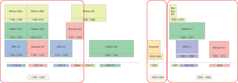
The first approach was to cover all of the possible GNSS frequency bands, although as more are added with time, we realized that this needed to be moderated somewhat. So the product covers L1, L2, L5 and their derivatives for the differing GNSS systems GPS, GLONASS, Galileo, and BeiDou, and also the Inmarsat commercial band to cover the proprietary augmentation signals used by many high-accuracy receivers (see Figure 1, red outlines).
FIGURE 1. Frequency bands, outlined in red, supported by the new record-and-replay device.
The next decision was what bandwidths to allow at each frequency, and how much of this bandwidth could be covered at once. The limitations here are driven by the data storage requirements of the signals being recorded, and the speed that they can be written to disk. The resulting solution allows bandwidths (BW) of up to 30 MHz at each frequency, and any three such bandwidths to be recorded at once. Physically, this is implemented with three channels with the ability to record any of the available frequencies or bandwidths. The user has, therefore, flexibility to set up recording for his particular needs, which may be just L1 covering BeiDou, GPS, Galileo, and GLONASS, or an L1,L2,L5, combination for a survey type application.
Of course, there are always requests for more capability, and we envisaged early on the ability to stack two devices to give six channels of 30-MHz BW for recording, say, GPS/Galileo and GLONASS at L1, GPS and GLONASS at L2, Galileo/GPS at L5, and an Inmarsat data carrier. See later for how this is achieved.
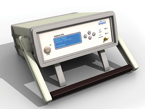
The whole product has to fit in a portable box with enough battery power for more than one-hour field campaigns, and also be capable of running from mains or vehicle power. The associated antenna needs to cover all of the frequency bands. Figure 2 shows the end result in its standalone configuration.
Figure 2. Portable solution for recording.
One additional requirement was placed upon the design, and that is the ability to record and replay non-GNSS data simultaneously with the GNSS signals, and reproduce them, if desired, in synchronism with the replayed signals. This allows time ticks, events, assistance data, sensor data, or even video to be stored and replayed along with the raw signals.
Architecture and Implementation
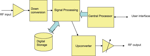
The new record-and-replay device uses a fast computer running the Linux operating system as its control center and storage/retrieval engine. Dedicated hardware is used to format or recover the raw data, and this has access directly to the computer bus to minimize the delays in writing or reading the mass storage, which in this case is a solid state hard drive (SSD). The overall architecture is shown in Figure 3.
Figure 3. Concept-level architecture.
The signal recording capability hinges around the RF planning, which has the task of supplying the necessary flexibility without adding more than minimal signal degradation.
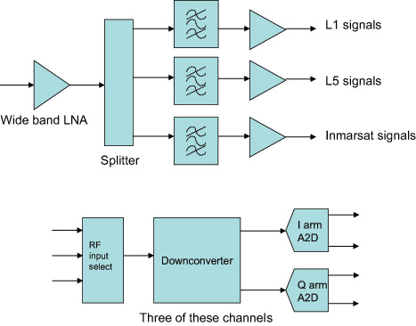
For the RF functionality, the device contains a broadband front end and a three-channel RF amplifier (L1, Imarsat, and L2/L5), filtering the signal down to reasonable bandwidths for later downconversion. Three independent channels of downconversion to baseband I and Q analog signals have access to any of the RF channels and are based upon satellite TV technology architectures. The downconverters have baseband filters that can be commanded to a desired bandwidth by the control processor. This allows the use of narrower bandwidths where possible, allowing more recording time for a lower sampling rate. The baseband signals are sampled at 10 MHz or 30 MHz, paying attention to the Nyquist requirements for pre-digitisation filtering. Two bits for each of the I and Q signals are utilized for packing into the recorded file format. Figure 4 shows the arrangement.
Figure 4 . The RF architecture.
At this stage any additional synchronous data to be recorded, such as truth or assitance data, is inserted into the bit stream, and the data from all the channels in use is combined in a pre-determined format. Dedicated hardware is used for this, and large data buffers are provided to alleviate bottlenecks in sending data to the disks. Each file has an associated definition in a header, and contains synchronization data to allow the device to set up the replay path and recover the data bits in order to reproduce whatever combination was recorded. Note that resulting data files are given the same extension, regardless of content. Data files can be very big (at maximum bandwidth we record about 2.7 Gbytes per minute) and may be difficult to handle once recorded. To assist with this, the device has a second, removable SSD on board, allowing recorded files to be simply popped out of the caddy and shared with another device, or even mailed or couriered. The RF path for the replay consists again of three independent channels, able to generate any of the supported frequencies and modulate upon them the original signals recovered from the stored file. Once again, dedicated hardware and large buffers are needed to unpack the files and send the RF data to the correct channels or to the synchronous data outputs in the case of recorded digital data, as determined by the file header.
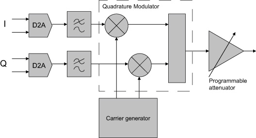
The data representing the recorded RF is converted back to analog form and filtered before being applied to modulators which regenerate the original channelized signals. Each channel has a programmable attenuator to “level” the amplitude, and the three channels are then combined together before passing through a common attenuator to provide user control over the replayed carrier to noise ratio (C/N0). Figure 5 shows the upconverter arrangement.
Figure 5. An upconverter channel.
All frequencies created within the device need to be traceable to a common reference. In addition, this reference needs to be at least as good as the reference in any receiver to be tested, since both its offset from true frequency and its rates of change will be superimposed on the replayed data. Many commercial-grade GNSS receivers (such as those used in mobile phone) are specifically designed to cope with poor oscillators, for instance a low-grade temperature controlled crystal oscillator (TCXO), whereas more professional receivers may expect a couple of orders of magnitude better performance. We decided, therefore, to include an ovenized oscillator (OCXO) for use both in record and playback modes. One challenge presented by this decision is that the oven is necessarily thirsty for power, and therefore a bigger battery is needed than would otherwise be the case.
The OCXO used is a 10.23-MHz component, thus allowing direct generation of the wanted GNSS frequencies using integer ratios and avoiding as much phase noise as possible in the various RF channels. A dedicated phase locked loop (PLL) generates a reference for output to other devices, and a 10-MHz input connector is provided to lock the OCXO to an external reference. These capabilities are utilized when combining two such devices, since we must have the same frequency reference in each. Apart from locking the two oscillators together, this configuration also needs time synchronization between the sampling in both devices, and this is achieved via an additional cable connected between the accessory connectors. Once time and frequency synchronized, the devices behave as a single six-channel unit, using external RF splitter/combiners for the RF connections.
Design Challenges
RF Total Bandwidth. The GNSS bands covered by the device range from the L5 band to the GLONASS L1 band, a total range of 480 MHz allowing for signal bandwidths. Table 1 shows the relevant bands.
Whilst the RF front end must be wide open to this range, assuming the use of a single RF input port, it is obviously necessary to provide bandwidth narrowing by filtering as soon as possible, to exclude jammers or carriers using the space between the GNSS bands, and to avoid the sheer noise power overwhelming the RF circuits. Examination of the supported GNSS services shows them essentially packed into two clusters of frequencies, which provide a convenient way of filtering down the RF input into two RF “channels.” This gets the total bandwidth down to about 180 MHz. Figure 1, the opening graphic for this article, shows the groupings. Beidou B3 and Galileo E6 are currently out of scope for this product, but will be supported in a later version.
The Inmarsat-supported signals are assigned their own RF path, since their structure is data modulated carriers, usually with low SNR. Elsewhere in the Inmarsat band there are more powerful carriers supporting comms traffic, which can “grab” the AGC and therefore cause loss of SNR during the digitization process. Hence this band is processed though its own RF path, maintaining as low a bandwidth as possible consistent with the frequency allocations of the various (proprietary) GNSS augmentation data carriers.
Tradeoffs. Throughput of the recording or replay paths is the performance limitation of the current architecture. Thus a lot of discussions and simulations concerning possible bandwidth, sampling rates, and bit depth tradeoffs was undertaken at the outset of the design. In addition, we needed to decide whether to sample signals at an IF frequency or at baseband. Trials were conducted to determine the real rates of disk access, which are different to the often quoted write and read speeds of computer interfaces.
The results of the trials and simulation led us to adopt a maximum average data rate to/from the storage system of 50 Mbytes/second, this being shown to be available over a period of many hours. Actually, at this rate we fill up a 1-Tbyte disk in about five hours.
To service the GNSS signal bandwidths of interest, again there are two groups of signals. This time we are looking at either the commercial signals (“open service signals” in some systems’ parlance) used by consumer-type receivers, which are relatively narrow band, and the military, high-accuracy, or resilient signals of interest to surveying and precision applications. Therefore, we offer two sampling rates, approximately 10 and 30 MHz, to avoid building large files where more than half of the bandwidth was of no interest to the user.
Next, we have to look at bit resolution. Given that we have generally a noise-like signal with Gaussian characteristics, if we were looking at digitizing at an intermediate frequency (IF), it can be shown that a 2-bit analog-to-digital converter (A2D) would be sufficient to keep the digitization losses to less than 1dB. Obviously, the fewer number of bits we need to store the better, commensurate with achieving the performance targets.
Frequency planning for all of the possible frequencies and bandwidths of interest is a complex task. The requirement here was to downconvert each signal of interest to a low IF suitable for digitizing, whilst having control of the bandwidth to eliminate unwanted signals and fulfill the Nyquist criterion. In addition, we wanted each channel to be isolated from the others even when the replay path involving the generation of the IF carriers was considered.
We therefore decided to downconvert to baseband for each channel, to avoid cross-contamination via the various IFs that would have to be generated for replay. In other words, we adopted an IF of zero Hz. This in turn means that the final bandwidth-determining filters are at baseband, and can readily be controlled by software means rather than having to switch RF paths. By downconverting into quadrature baseband channels, all stored signals are at the same (zero) IF, and crosstalk and imaging during upconversion is avoided.
Thus the A2D architecture of 2 bits in the inphase (I) and 2 bits in the quadrature (Q) arms of the downconverted signal was adopted. Doing the calculation in terms of stored data, we see that we can operate three channels inside our target storage bandwidth, with a margin left for other features such as storing video at the same time.
For 30M samples per second (SPS), each channel has 4 bits or 0.5 bytes
Therefore, for three channels the storage bandwidth is 0.5 * 3 * 30 MSPS, or 45 Mbytes/s
To keep the optimum A2D characteristics, the AGC is designed to adjust the signal amplitude at the converter to give a Gaussian response to the four states determined by the two bits in each arm. The AGC operates independently in each channel. Figure 6 shows the final architecture for the device in block diagram form.
Figure 6. Final architecture.
Real-Time Data Handling. Storage and retrieval of the digitized signals is carried out by dedicated hardware connected to the RF downconverter, the playback upconverter, and the main computer that “owns” the storage media. Large buffers allow the storage media to lag (record) and lead (playback) the real-time signals in time, and to take short breaks for housekeeping functions. Data is packed into a binary file according to a pre-determined sequence, which in turn is set by the number of channels and bandwidths in use. A file header is generated which contains all of the information necessary for reconstructing the data streams for replay. A synchronization sequence is added at the start of the file to allow recovery of the correct bits for each channel and each baseband quadrature arm, and to the correct timeslots for each component. Destroying the correct time reproduction is the most likely issue to cause faulty replay in any record/replay device. GNSS receivers don’t like discontinuous or slewing time!
This approach also allows the insertion of external digital data into the file. Providing the data processing hardware is aware of the individual bits into which this data is placed, digital data recorded at the same time as the raw signals may be regenerated synchronously during replay. Thus any data that is applied to a receiver in a real time trial can be available for the same trial any time after the event. Two streams of synchronous data can be recorded per channel potentially making six serial data streams per chassis available.
User Interfaces
A final challenge presents itself in the case of user interfaces. Although the operational options of the device are quite complex, there is a requirement to be able to capture field data with just the equipment itself and any necessary antenna setup. Consequently, the product has a display and control keys implemented on the front panel, allowing the user comprehensive access to the internal functions using a menu system and scrolling displays. Alternatively, for operation in a lab environment, a network connected user interface is specified, and this requirement is supported by a webserver running on the main processor in the device. Thus, simply opening a web browser and connecting to the device’s IP address allows full functional control.
In addition, connecting a mouse, keyboard, and monitor to the device allows access to the main processor, allowing the running of scripts thus providing full control of replays and receiver functions for running continuous tests in an automated laboratory environment. Using this approach, receiver modifications can be tested over many scenarios and locations many times each, to provide statistically relevant results, without taking up operator time. Remote monitoring is possible using the webserver.
Performance Testing
A range of tests and trials have been carried out to verify that the product meets its specifications, and to measure the performance in a number of real life scenarios.
Repeatability, Degradation, Attenuation. The first and most obvious thing to explore is the effect of the record and playback on signal-to-noise ratio. Since the RF circuits add some noise to the signal recorded, we would expect some degradation to take place here. Also, during replay, the receiver under test adds more noise, depending on its noise figure, although this should be the same as would be added when using “live” signals. Many receivers adjust for their noise figure when reporting C/N0 numbers (C/N0 is a signal to noise measurement normalized to a 1-Hz bandwidth and is the standard reported measurement for most GNSS receivers). However, by replaying back the recorded signal and noise at a higher level than would have been received in “live” conditions, we can eliminate almost all of the degradation. In live versus replayed tests for individual satellites using a JAVAD receiver, which allows us to test all of the supported bands and constellations, we found that replay is possible within ±1 dB of the original live signals. Replayed signals were about 10 dB above the original recorded level to achieve this, effectively swamping the receiver’s noise contribution.
An interesting aspect of controlling the C/N0 this way is the ability to attenuate the replayed signal and, therefore, increase the contribution of the test receiver’s noise figure. Thus, although the recorded C/N0 hasn’t changed, we can attenuate the replay level and use the receiver to add noise.
This process is not linear, and we obviously have to remove nearly all of the 10-dB excess to get started. The device keeps a table of attenuation vs C/N0 reduction, allowing the user to simply dial up the required C/N0 loss. Since this depends on the receiver noise figure, effects may differ slightly from receiver to receiver. Usefully the table is user definable allowing tailoring to a specific receiver.
Losses from Phase Noise, Other Factors. This category of degradation is more difficult to quantify, since the effects are on tracking and therefore range and phase measurement rather than signal to noise ratio. One way of looking at this is, therefore, to establish the positioning performance during live and replayed sessions, and measure the differences. This has some complexity, though, since putting the same signals into a receiver multiple times yields differing performance each time, meaning that we have to use some statistical analysis. Of course this isn’t possible on live signals, and is one reason why repeatable replayed signals are so important in developing GNSS receivers. Another aspect is the fact that some of the effects are differential among frequency bands (filter delays, for instance) and across bands as well (group delay) and also occur in the receiver under test, which will have been calibrated to mitigate its own contribution.
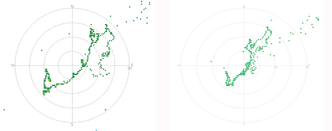
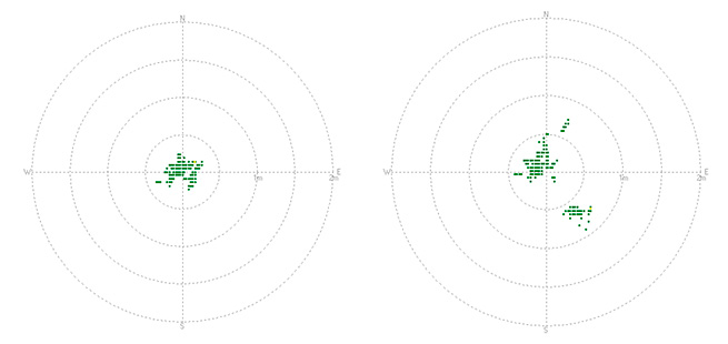
Figure 7 shows a comparison of static positioning for live and replayed signals using only GPS L1 and a 10-MHz sampling rate with an ST-Ericsson receiver, whilst Figure 8 is from a JAVAD receiver using all possible signals in live mode and GPS L1/L2 and GLONASS L1 in replay. In both cases the degradation is within 1 meter always, and much less than this when statistically analyzed.
Figure 7. Static position GPS L1 comparison: live left, replayed right.Figure 8. GPS L1/ L2 with GLONASS L1 comparison.
Another opportunity to measure the effects is to run a zero baseline phase solution, whereby the receiver is used as the “base station” when receiving live signals which are simultaneously recorded. During replay, the same receiver is used as the “rover” with RTK corrections coming from the previously captured live session. In this setup, therefore, we are really only measuring differences in the replayed and live signals, and the usual measurement limitations of the receiver.
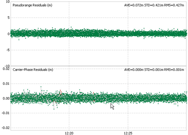
Figure 9 shows the results of one such test, with the pseudorange and carrier phase residuals plotted. This was carried out using two devices in master/slave mode recording GPS L1, L2, L5, and GLONASS L1, L2. As can be seen, the residuals are within “normal” expectations and are measured as 0.42 m RMS for the pseudorange and 1mm RMS for the carrier phase.
Figure 9. Residuals from zero baseline replay.
Drive Test
One of the most common uses for the recorder is to capture the signals at a particular time in a chosen “difficult” environment, A number of representative trials were carried out and we were able to demonstrate consistent results and repeatability. In some cases, the replayed signals yield better performance than live ones, which of course is possible given the differing receiver responses per signal run.
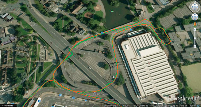
Also, the more times a receivers sees the same time span, the more ephemeris and iono data it can build up, especially true of built up areas where data acquisition is difficult. Figure 10 shows a small section of the City of Coventry in the UK, where the green trace is the “live” plot and the replayed one is in orange. Much of this route is under roads or buildings.
Figure 10. Live and replayed drive around in Coventry.
Dynamic Range and Fidelity
When jamming signals are introduced, the dynamic range comes into play. The earlier discussion of the 2-bit I and 2-bit Q architecture is tested here as the performance of the AGC and A2D is critical in maintaining the fidelity of the GNSS signals in a jamming environment. Note that we are not addressing deliberate jamming here, any “controlled” jammers can be added with an RF mixer at replay. Instead, we are concerned with the everyday jamming environment encountered just about everywhere electronic equipment is deployed.
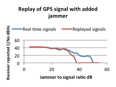
A test was carried out to determine the dynamic range of record/playback paths. A simulator was used as a GPS L1 signals source, and progressively larger jamming signal added via an RF power combiner. The resultant C/N0 in a test receiver was plotted using the live signals which were recorded at the same time. A subsequent replay of those signals was then plotted on top of the original C/N0s. The result is in Figure 11.
Figure 11. Results of the increasing jammer test.
As can be seen, with low jammer powers the real-time and replayed C/N0s track very closely. The ST-Ericsson receiver we used has some signal processing mitigation built in, and so only shows slow degradation as the jammer power is increased. In the real-time run, it was able to track satellites with the J/S ratio greater than 44 dB (and therefore >25 dB above the noise)
On the replayed line, we see the dynamic range limitations start to dominate the replayed signal when the J/S reaches about 30 dB, or 11 dB above the noise, which aligns well with the theoretical analysis of the digitization strategy. This range is sufficient for most environments encountered in real tests.
In Use and Additional Capabilities
With so much flexibility we find that users have a diverse range of applications for the device. These range from multi-constellation usage at L1 only, allowing BeiDou, Galileo, GLONASS, and GPS to be captured, to full six-channel recordings using GPS, GLONASS, and Galileo at L1, L2, and L5 along with an Inmarsat-based assistance channel. For the first time in this class of device, recording of the “military” bandwidth signals is possible. User feedback has been favorable, especially since the unit opens up new capabilities for receiver development and testing.
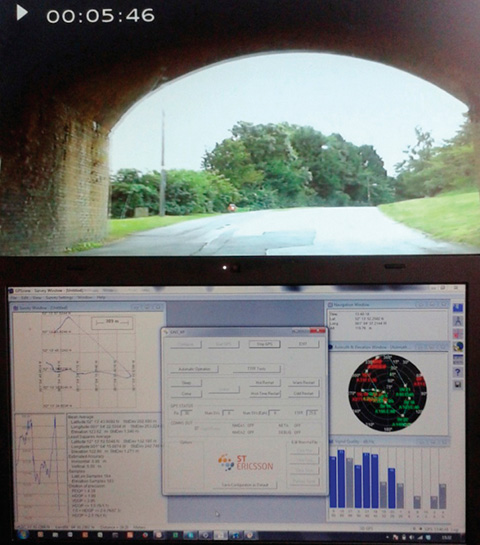
A small margin of recording bandwidth has been put to use with the ability to record video alongside the raw GNSS signals, and to replay it simultaneously. This allows developers not only to see the performance of their receiver in difficult signal environments, but also to gain a visual idea of the physical environment. Figure 12 shows a receiver control panel along with video pictures of the recorded environment.
Figure 12. GPS L1 and video synchronized replay
Conclusion
Early user feedback has validated the concept behind the device. Although the device will cover additional GNSS constellations and bands as they become operational, for the present the technology is stretched about as far as it can be consistent with the development of a timely and cost effective device. We will continue to address the compromises in the search for more performance, no doubt pushed by user demands.
Acknowledgment
The authors thank their colleagues at Integrated Navigation Systems and Spirent UK for support and access to design and user information.
Steve Hickling obtained his joint physics and electronics degree from the University of Birmingham. He is responsible for Spirent’s GNSS test solutions as lead product manager in the positioning business.
Tony Haddrell obtained his degree in physics at Imperial College, London, and is technical director at integrated Navigation Systems. He is a consultant to GNSS companies and a visiting lecturer at Nottingham University.
Plans to harness Galileo and other satnav systems for next-generation satellite augmentation systems for aviation and other high-performance uses took a significant step forward at the latest gathering of worldwide operators and experts, reports the European Space Agency.
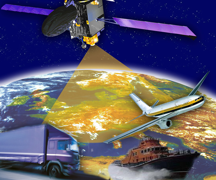
Satellite augmentation systems combine additional ground stations and satellite transponders to sharpen satnav accuracy and reliability across given geographical regions — based on the U.S. GPS for now, but with plans to move to a multi-constellation design additionally employing Europe’s Galileo, China’s BeiDou, and Russia’s GLONASS systems in the post-2020 era.
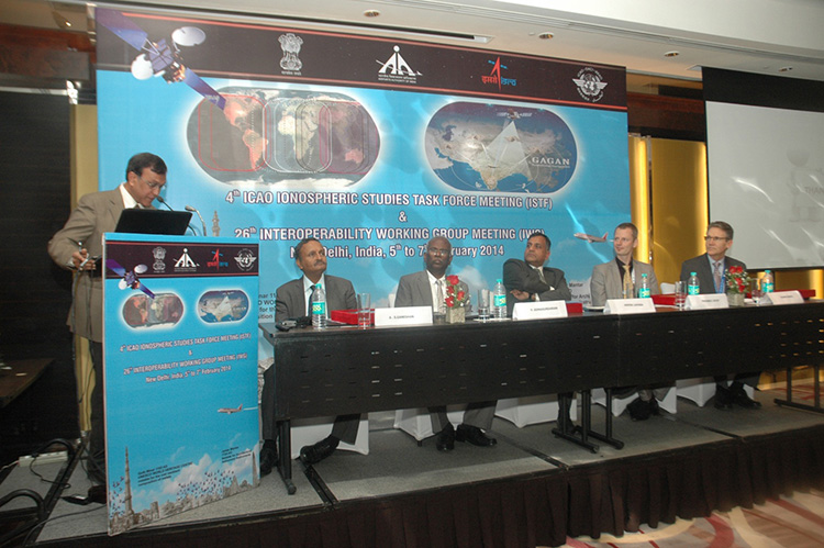
The 26th Satellite Based Augmentation Systems (SBAS) Interoperability Working Group (IWG) took place in New Delhi, India on February 5–7.
The 26th SBAS Interoperability Working Group (IWG) was introduced by V. Somasundaram, board member of the Airport Authority of India.
Among its achievements was to converge on a standard message definition for one of the channels — known as L5 — of the planned second-generation SBAS systems, which will utilize dual-frequency, multi-constellation signals.
“Two solutions had been put forward, one by ESA based on work by European industry and one from the U.S. Federal Aviation Administration and Stanford University,” explains ESA’s Didier Flament, co-chair of the IWG.
“A single definition coordinated between both bodies has been presented, combining the benefits of both solutions. The formal IWG review and approval loop has now been started with the objective of finalizing it for September’s IWG meeting.
“The aim is to have it ready to submit to the official international SBAS standardization bodies — the International Civil Aviation Organization and the Radio Technical Commission for Aeronautics — as soon as October.”
The meeting also marked the significant progress made by Indian’s own SBAS system GAGAN, which underwent its final stability test last summer, followed by its safety certification in December.
At this point GAGAN was declared certified for non-precision approach users , followed by its safety-of-life service being formally offered to civil aviation users on 14 February.
GAGAN has been jointly undertaken by the AAI and the Indian Space Research Organisation, intended to provide improved accuracy, availability and integrity necessary to enable users to rely on satnav signals for all phases of flight – from en route as well as approach to all qualified airports within the GAGAN service area.
SBAS services worldwide
EGNOS is an operational precursor to Europe’s Galileo global satnav system.
GAGAN is the fourth certified SBAS to enter servicer worldwide. Europe has the European Geostationary Navigation Overlay Service (EGNOS), which was designed and built by ESA then turned over for operation by the European Satellite Service Provider, ESSP, overseen by the European Global Navigation Satellite System Agency (GSA) — both of whom also participated in the meeting. ESA retains responsibility for the future evolution of EGNOS.
The U.S. has the Wide Area Augmentation System (WAAS), developed and operated by the Federal Aviation Administration, with an extension over Canada called CWAAS (Canadian WAAS). WAAS celebrated its 10th anniversary of operational life last July.
Japan has the Multi-functional Satellite Augmentation System (MSAS), developed and operated by Japan’s Civil Aviation Bureau. Japan is currently discussing plans to merge this capability with their new home-grown satnav system, QZSS.
Along with GAGAN, the meeting also covered the progress made by the other SBAS systems under definition or development — the Russian SDCM, Chinese SNAS and Korean K-SBAS.
The follow-up IWG meeting is due to take place in September in Tampa, Florida.
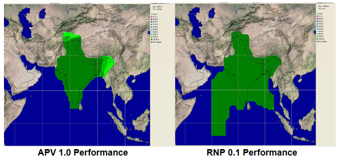
Planned GAGAN service coverage for the two different service levels (RNP0.1 and APV1). GAGAN has been jointly undertaken by the Airport Authority of India and the Indian Space Research Organization, ISRO, to achieve smooth transition to satellite-based navigation and seamless air traffic management across continents. GAGAN is designed to provide improved accuracy, availability and integrity necessary to enable users to rely on GPS for all phases of flight, from en route through approach for all qualified airports within the GAGAN service volume. More precisely it is aimed to provide Non Precision Approach RNP0.1 service levels to the entire Indian Flight Information Region and Precision Approach APV1 service (equivalent to the current EGNOS Service) within a specified service volume within Indian land mass.
Tackling ionospheric interference
The New Delhi IWG took place concurrently with a related meeting, the ICAO’s 4th Ionospheric Study Task Force. This group has been tasked with the objective of developing region-specific models of ionospheric models to compensate for satnav signal interference or loss.
The ionosphere, the electrically sensitive outer shell of Earth’s atmosphere, can be perturbed by solar activity. And because satnav signals pass from space by Earth they can then be disrupted in turn. Equatorial regions see the greatest disturbance, including signal delay or ‘scintillations’ making signals unstable.
The aim is to develop reliable ionospheric models to compensate for these effects, particularly for equatorial SBAS regions, such as India. ESA is contributing with data from its worldwide Monitor network, gathering data to improve future EGNOS performance and potentially support further geographical extension.
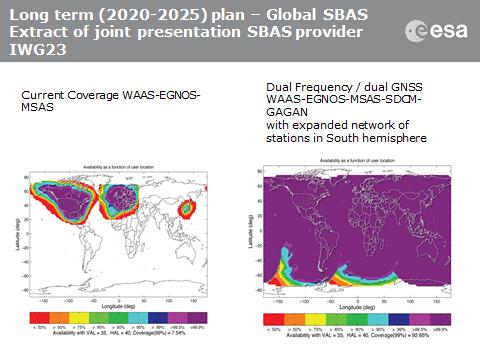
Comparing current worldwide SBAS coverage — based on WAAS, EGNOS and MSAS — to the situation envisaged for 2020–25: near-global coverage based on WAAS, EGNOS, MAAS, SDCM and GAGAN, with an expanded network of stations in the southern hemisphere, based on a common dual-frequency/dual satnav standard being finalized by the SBAS IWG.
GeoLearn, a start-up devoted to servicing the geospatial industry with online learning and continuing education credits, has launched its website and training portal with an initial catalog of 22 one-hour-long courses taught by industry-leading faculty members. Course topics available at launch include “Unmanned Aerial Vehicles (UAV’s),” “ALTA/ACSM Land Title Surveys,” and “National Flood Plain Insurance.”
“We want to provide quality professional development to satisfy continuing education requirements that also enables you to deliver services to your clients from a higher quality knowledge base,” said GeoLearn Principal Joe Paiva. “You often have to get continuing education to satisfy licensing requirements; at GeoLearn you will also leave enriched — a plus for any geospatial organization.” While catering to professionals, GeoLearn will begin to build up courses suitable for technicians as well, including a series that supports those pursuing Certified Survey Technician (CST) status.
GeoLearn faculty members are nationally recognized experts in the geospatial field. Initial faculty include Gary Kent of the Schneider Corporation, Wendy Lathrop of Cadastral Consulting and GeoLearn Principal Joseph Paiva. More courses will come soon from other notable professionals in the geospatial industry.
“A key motivation to start GeoLearn has been the desire to significantly improve the learning experience for busy professionals and technicians,” said GeoLearn Principal Bob Morris. “With limited time availability and the growing cost of travel associated with more traditional methods of securing continuing education credits, we hope to provide an attractive option using of state-of-the-art multi-media through our online training portal.”
GeoLearn has invested in a multi-camera video production studio optimized for online learning, and hired Emmy Award-winning marketing and video expert Peter Barrett to head up those efforts.
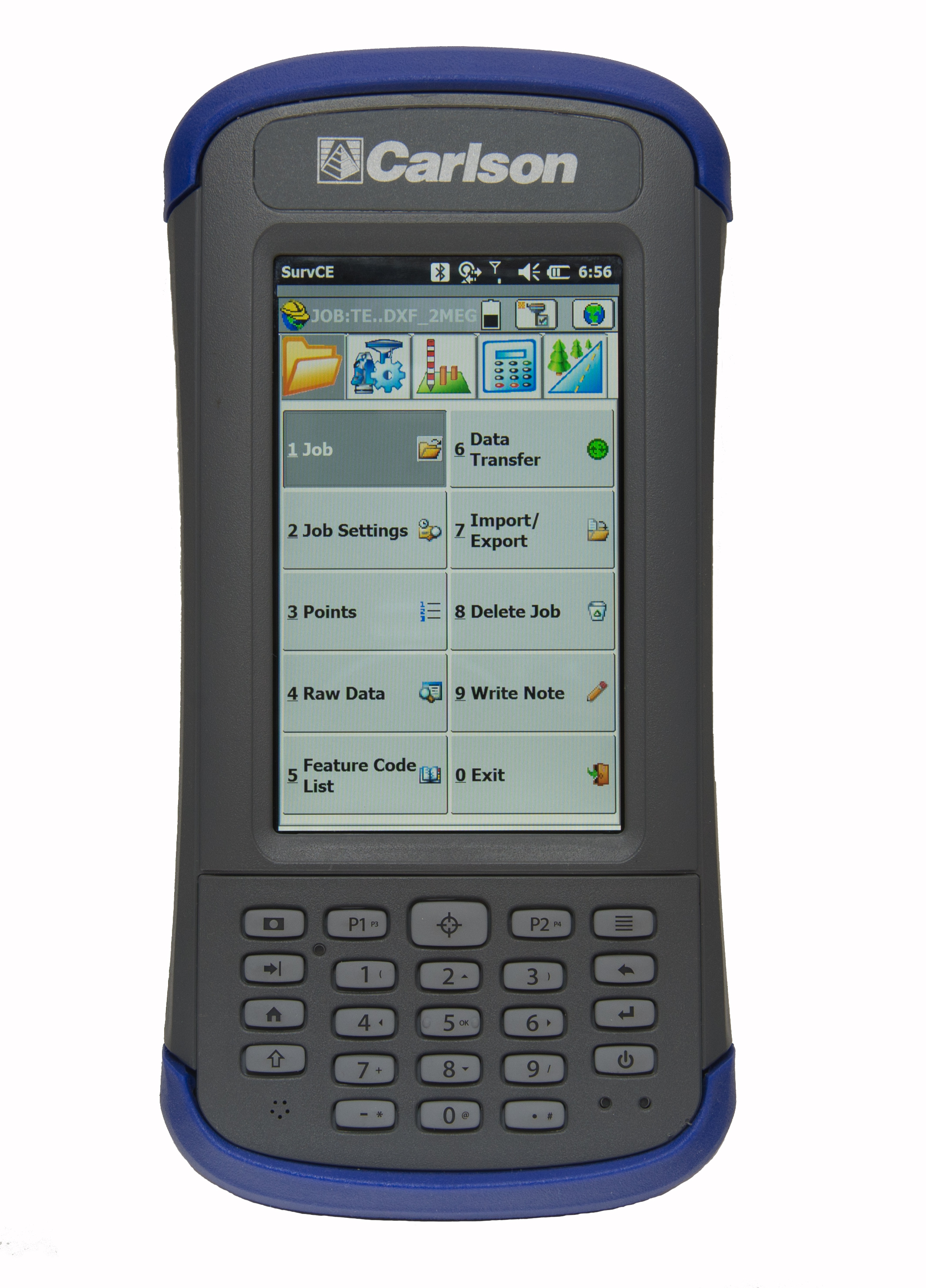
Carlson Software’s newest data collector, the Carlson MINI2, packs a punch for its compact size. The new handheld computer is taking the place of its predecessor, the Carlson MINI.
With an IP68 rating (better than the original MINI), the MINI2 is waterproof and dustproof, and is tested to MIL-STD-810G to meet the environmental demands of the surveying industry. The MINI2 also has several advancements over the MINI, including a bright display, a custom battery that lasts 20+ hours on one charge, and a scratch-resistant capacitive touchscreen with glove-friendly numeric keypad, for faster and more accurate data entry.
The Carlson MINI2 was designed and manufactured by Juniper Systems, which specializes in building ultra-rugged handheld computers. Juniper Systems also manufactures the Carlson Surveyor handheld computer. Carlson Software packages these rugged handhelds with its own software to provide a total solution for surveying professionals.
“Carlson Software has been a great partner of Juniper Systems for many years now,” said Debbie Trolson, Geomatics Market Manager at Juniper Systems. “Their high level of service as well as their attention to customer needs has made them not only an excellent company, but also a leader in the surveying market. I believe our cooperation with Carlson in providing the MINI2 to surveying professionals will continue to strengthen our partnership for years to come.”
“Working with the team at Juniper Systems has allowed Carlson to offer our customers the kind of rugged and reliable hardware they need out in the field,” said Butch Herter, director of Hardware for Carlson Software. “The Juniper-produced MINI2 and Surveyor are the perfect complement to Carlson’s popular and efficient data collection software choices.”
A software-based GNSS receiver is now available on Tensilica ConnX DSP IP cores, according to an announcement by Cadence Design Systems and Galileo Satellite Navigation, Ltd. (GSN), a developer of multi-system GNSS products including software receiver technology. The core is being demonstrated at the Cadence booth at Mobile World Congress, being held this week in Barcelona, Spain.
The GSN GNSS receiver running on a Cadence ConnX BBE16 DSP consumes very little power — as low as 10mW of power on a 40nm process — and has the ability to work in lower rates, or snapshots for ultra-low-power mobile scenarios. The solution delivers high-sensitivity tracking, offering a seamless GNSS experience in challenging environments, the companies said.
“GSN’s software-based approach for satellite receivers perfectly complements Cadence DSPs, taking maximum advantage of the flexibility of our DSP architecture,” said Jack Guedj, corporate vice president of Research and Development at Cadence. “The availability of GSN’s software on our ConnX BBE16 further reinforces the strength of our low-power programmable modem strategy for advanced communications.”
“The Tensilica ConnX BBE16 DSP delivers outstanding performance for implementing our GNSS receivers and with a low-power footprint. This provides customers with the ability to easily upgrade their designs to include future satellite systems including Beidou, GLONASS, and Galileo via software,” said Eli Ariel, CEO at GSN. “With no additional silicon costs and at a low cost of deployment, this software-based solution results in a very compelling approach to implement satellite navigation functionality in many products where it otherwise might be impractical.”
Honeywell Aerospace’s LASEREF VI navigation system has been selected by Airbus Helicopters for its light helicopter platforms, the EC145 T2 and EC645 T2 family.
The LASEREF inertial reference unit (IRU) allows helicopter operators to always have an autonomous navigation source available in the absence of a GNSS and radio navigation. The capability is especially useful when navigating during a mission when the GNSS is unavailable due to terrain masking, limited satellite constellation availability, or unintentional or intentional jamming.
“LASEREF will provide Airbus Helicopters with exactly what they’re looking for — an always-available and highly reliable navigation system,” said Varant Panossian, customer business manager at Honeywell Aerospace. “When you’re in extreme situations, navigation is essential for everything from crew safety to completing critical missions.”
Designed for fixed-wing and rotary-wing applications, the LASEREF is a light, small IRU that delivers the highest reliability in the industry, according to Honeywell. Its integration with GPS prevents delays in information delivery and keeps operations running safely and efficiently even under harsh environments and demanding mission situations.
GeoLearn, a start-up devoted to servicing the geospatial industry with online learning and continuing education credits, has launched its website and training portal with an initial catalog of 22 one-hour-long courses taught by industry-leading faculty members. Course topics available at launch include “Unmanned Aerial Vehicles (UAV’s),” “ALTA/ACSM Land Title Surveys,” and “National Flood Plain Insurance.”
“We want to provide quality professional development to satisfy continuing education requirements that also enables you to deliver services to your clients from a higher quality knowledge base,” said GeoLearn Principal Joe Paiva. “You often have to get continuing education to satisfy licensing requirements; at GeoLearn you will also leave enriched — a plus for any geospatial organization.” While catering to professionals, GeoLearn will begin to build up courses suitable for technicians as well, including a series that supports those pursuing Certified Survey Technician (CST) status.
GeoLearn faculty members are nationally recognized experts in the geospatial field. Initial faculty include Gary Kent of the Schneider Corporation, Wendy Lathrop of Cadastral Consulting and GeoLearn Principal Joseph Paiva. More courses will come soon from other notable professionals in the geospatial industry.
“A key motivation to start GeoLearn has been the desire to significantly improve the learning experience for busy professionals and technicians,” said GeoLearn Principal Bob Morris. “With limited time availability and the growing cost of travel associated with more traditional methods of securing continuing education credits, we hope to provide an attractive option using of state-of-the-art multi-media through our online training portal.”
GeoLearn has invested in a multi-camera video production studio optimized for online learning, and hired Emmy Award-winning marketing and video expert Peter Barrett to head up those efforts.
Northrop Grumman has been selected by AgustaWestland to supply the LCR-110 Inertial Reference System for the new AW609 TiltRotor aircraft.
Northrop Grumman Corporation has been selected by AgustaWestland, a Finmeccanica company, to provide flight-critical inertial instruments on the new AW609 TiltRotor aircraft undergoing civil certification through the Federal Aviation Administration.
The LCR-110 Inertial Reference System and the LCR‑300A Air Data Attitude Heading Reference System have been chosen as standard inertial navigation products for the advanced AW609 TiltRotor. The LCR‑110 features a high-performance, fiber-optic gyro-based inertial measurement unit and an advanced micro-electromechanical system (MEMS) triad accelerometer. The system offers hybrid navigation via GNSS data, in addition to aircraft autonomous integrity monitoring for GPS signal integration and integrity checks. These features are essential for precise Required Navigation Performance flight operations.
The LCR‑110 evolved from the successful, longstanding LCR‑100 product family that has been selected for numerous rotorcraft and fixed-wing platforms.
The systems were developed by Northrop Grumman Navigation and Maritime Systems Division’s subsidiary in Germany, Northrop Grumman LITEF.
“This suite of combined equipment provides critical flight control and navigation data to help the aircraft achieve required availability, precision and the highest levels of integrity,” said Eckehardt Keip, managing director for Northrop Grumman LITEF. “Our products enhance precision navigation operations, improve safety margins, save weight and volume, and provide attractive commercial advantages.”
The LCR‑300A is being introduced after several years of independent research and development. The system’s MEMS gyro provides advanced attitude heading reference system performance in combination with a magnetic sensing unit. It also features directional gyro mode, which minimizes magnetic compass errors.
The digital air data computer module, which is embedded in the LCR‑300A, was developed by Curtiss-Wright Corporation’s Defense Solutions division. It weighs less than 0.9 pound, yet contains the pneumatic sensors and processing electronics to generate the complete International Civil Aviation Organization air data parameter set. The module is designed using the latest high stability, low drift pressure transducer technologies, providing exceptional repeatability and reliability, Northrop Grumman said.
The twin engine, fly-by-wire AW609 TiltRotor combines the benefits of a helicopter and fixed-wing aircraft into one platform. The aircraft is a natural choice for civil and para-public roles, flying above adverse weather conditions at 25,000 feet in a comfortable and pressurised cabin at twice the speed and the range typical of helicopters.
Rx Networks, Inc., a mobile location technology and services company, has completed the upgrade of its GPStream Global Reference Network (GRN) to include the BeiDou constellation. A top-tier GNSS semiconductor vendor has already incorporated this new feature so its platform can take advantage of the extra satellites now available in the BeiDou constellation, the company said.
Global real-time assistance and high-accuracy long-term orbit and clock prediction products are now uniformly available across the GPS, GLONASS and BeiDou constellations. In the second quarter of 2014, BeiDou support will also extend to GPStream PGPS — Rx Networks’ popular synthetic A-GNSS software that has been deployed in more than 100 million smartphones and personal navigation devices worldwide.
In commercial service since 2006, the GPStream GRN is a collection of 26 highly reliable earth stations deployed in 21 countries. It forms the foundation underneath many of Rx Networks’ products, on which nearly a billion devices rely for their GNSS performance. The network is highly redundant and, combined with a carrier-grade service delivery network, is provided with a 99.999 percent service-level availability (SLA). A further upgrade, to support the European-run Galileo constellation, will be available later this year.
From network operators’ commercial and E911 location servers to GNSS chipset vendors and device OEMs, the addition of BeiDou means faster and higher availability GNSS location fixes.
“The addition of BeiDou to our existing GPStream GRN service meant a complete overhaul of our reference network and service delivery architecture while maintaining the 99.999 percent SLA we’re well known for,” commented Guylain Roy-MacHabee, CEO of Rx Networks. “As multi-GNSS chipsets come to market, there is commensurate requirement for a uniform, reliable and device-independent assistance data service like our GPStream GRN.”
Mediatek has released a five-in-one combo wireless system-on-a-chip (SOC), with multi-system GNSS, to support full featured smartphones, tablets, and other premium mobile devices.
The MT6630 dramatically reduces the component count and eBOM while improving ease-of-design for manufacturers by eliminating external low noise amplifiers and integrating the Wi-Fi 2.4 GHz and 5 GHz power amplifiers, Bluetooth power amplifiers, and transmit-receive (T/R) switch into a PCBA footprint less than 65 square millimeters.
Features include:
Concurrent tri-band reception of GPS, GLONASS, Beidou, Galileo, and QZSS with industry leading sensitivity, low power, positioning accuracy, and the longest prediction engine
Dual-band single-stream 802.11a/b/g/n/ac with 20/40/80MHz channel bandwidth
802.11v time of flight protocol support and management engines to enable higher accuracy of indoor positioning via Wi-Fi
Advanced support for Wi-Fi Direct Services and Miracast optimization for easier pairing, increased robustness, advanced use-cases, and lower power
Bluetooth 4.1 with Classic, High-Speed and Low-Energy support, and ANT+ for compatibility with the latest fitness tracking, health monitoring, and point of information devices and applications
FM transceiver with RDS/RBDS
Integrated engines and algorithms for full concurrent operation and co-existence, including industry-leading throughput during LTE transmission
The MT6630 delivers full concurrent operation of all 5 systems operating at maximum compute intensity with no degradation compared to single-system operation while offloading the mobile device CPU for design ease and extended battery life.
As a focus on low power and digital home convergence, the MT6630 uses a configurable PA architecture to save current at commonly used power levels, including those used for Miracast Wi-Fi Direct services. The MT6630 implements advanced co-existence techniques, including for LTE to deliver industry-leading throughputs. The MT6630 also supports Wi-Fi diversity for premium smartphones and tablets to improve antenna angle sensitivity and handheld scenarios.
“The MT6630 makes it simple for manufacturers to bring mobile devices to market with sophisticated wireless features, lower power and uncompromised performance,” said SR Tsai, general manager of MediaTek’s Connectivity Business Unit. “The MT6630 furthers MediaTek’s focus to deliver the best experiences across the digital home and mobile applications by using its unique leadership position in digital TV host processors, smartphone platforms, and connectivity.”
The small-footprint design is available in 5 x 5-mm wafer-level chip-scale package (WLCSP) or a 7 x 7 mm quad flat no-leads (QFN) and requires only 44 components, which is around half that of other integrated wireless solutions, the company said.
Mediatek’s MT6630 is sampling now and complements the recently announced MT6595 octa-core SOC with LTE for premium mobile devices. The first commercially available devices to use the MT6630 are expected in the second half of 2014.
Anritsu Company is launching an internal atomic clock option for its MS2720T Spectrum Master handheld spectrum analyzer that allows users to acquire excellent frequency accuracy, including in environments in which the GPS cannot be used.
Integrating the atomic clock inside the MS2720T provides field engineers and technicians with a durable, handheld spectrum analyzer that can deliver the extremely high accuracy necessary to prove regulatory compliance.
By using the atomic clock, users can acquire a very accurate frequency reference without the need of the GPS. Calibration accuracy of the atomic clock is 1×10⁻⁹. The MS2720T can be configured with the GPS receiver and the atomic clock to achieve both high-frequency accuracy and GPS location stamping of measurements.
Because the atomic clock module mounts inside the instrument, there are no loose cables that can potentially snag on branches, antennas or other extensions prevalent in the field environments in which the MS2720T is used, the company said. The atomic clock is automatically used once it is installed.
The Spectrum Master MS2720T series features the highest performance handheld spectrum analyzers on the market, the company said. Providing field technicians and engineers with performance that rivals a benchtop spectrum analyzer, the MS2720T features a touchscreen and best-in-class performance for dynamic range, DANL, phase noise, and sweep speed, providing unprecedented levels of spectrum monitoring, hidden signal detection, RF/microwave measurements, and testing of microwave backhauls and cellular signals.
Continuous frequency coverage from 9 kHz to 20 GHz is provided by the MS2720T with the option 1 internal atomic clock. An improved sweep mode allows users to set resolution bandwidth from 30 kHz to 10 MHz with minimal effect on sweep speed. Because the sweep speed with a 30 kHz bandwidth is nearly the same as a 10 MHz RBW, sensitivity can be selected without the need for long sweep times.
The MS2720T has dynamic range of > 106 dB in 1 Hz RBW, DANL of -163 dBm in 1 Hz RBW, and phase noise of -112 dBm @ 10 kHz offset at 1 GHz. These best-in-class specifications are complemented by unprecedented measurement capabilities. A burst detect sweep mode function allows emitters as short as 200 microseconds to be captured every time, allowing the MS2720T to detect bursty signals that can lead to finding intermittent or bursty emitters. The burst detect sweep mode increases sweep speed more than 1,000 times in a 15-MHz span.
The internal atomic clock has a U.S. price of $5,900 and is available in 6 to 8 weeks.