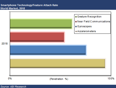
Accelerometers, gyroscopes, near field communications (NFC), and gesture recognition are predicted to be the big winners in mobile devices. These mobile technologies are projected to make the greatest penetration gains over the coming years, according to a recent study by market intelligence firm ABI Research.
“Hands-free operation or gesture recognition is soon going to become a key differentiator in high-end flagship smartphones, media tablets, and smart glasses,” says senior analyst Joshua Flood. “Samsung’s latest Galaxy S4 has already incorporated the technology within its handset and has received significant plaudits for its new innovative user experience. Furthermore, with a host of new smart glass products soon to be released, it is easy to imagine the usefulness of the interface with this product.” In 2013, almost 12% of smartphones shipped will have vision-based gesture recognition capabilities.
Accelerometers and gyroscopes play a crucial role with today’s mobile devices, enabling devices to be more intuitive and take action without a user pressing a button. Simple actions like switching from portrait to landscape when a smartphone is tilted are made possible by including these components. Additionally, the fast growing mobile gaming market is highly dependent upon smartphones including gyroscopes, which enhance gaming experience. Nearly half of the smartphones shipped this year will include these MEMS sensor types.
NFC has been one of the most talked about mobile technologies that has not quite taken off. The technology has primarily been focused around mobile payments; however, mobile OEMs have begun to see other potential capabilities for the technology such as photo-sharing and location information tag points that could open a huge market for advertising and marketing campaigns. Within three years, it is anticipated one in two smartphones shipped will include NFC and have gesture recognition capabilities. Furthermore, accelerometers and gyroscopes will be the “norm” with most smartphones.
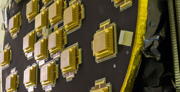
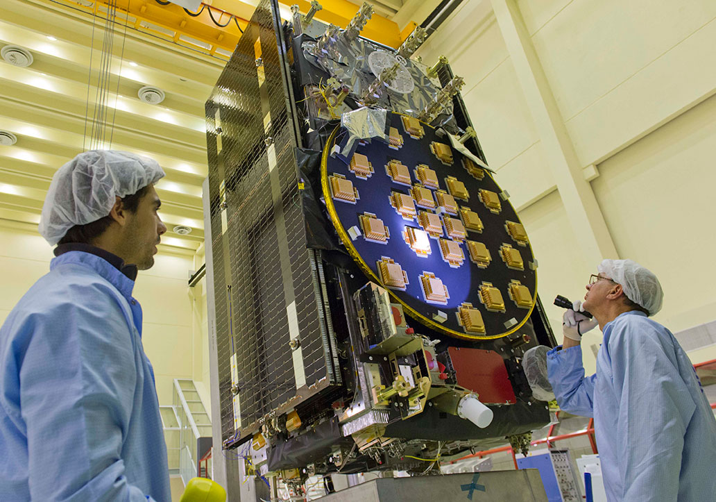
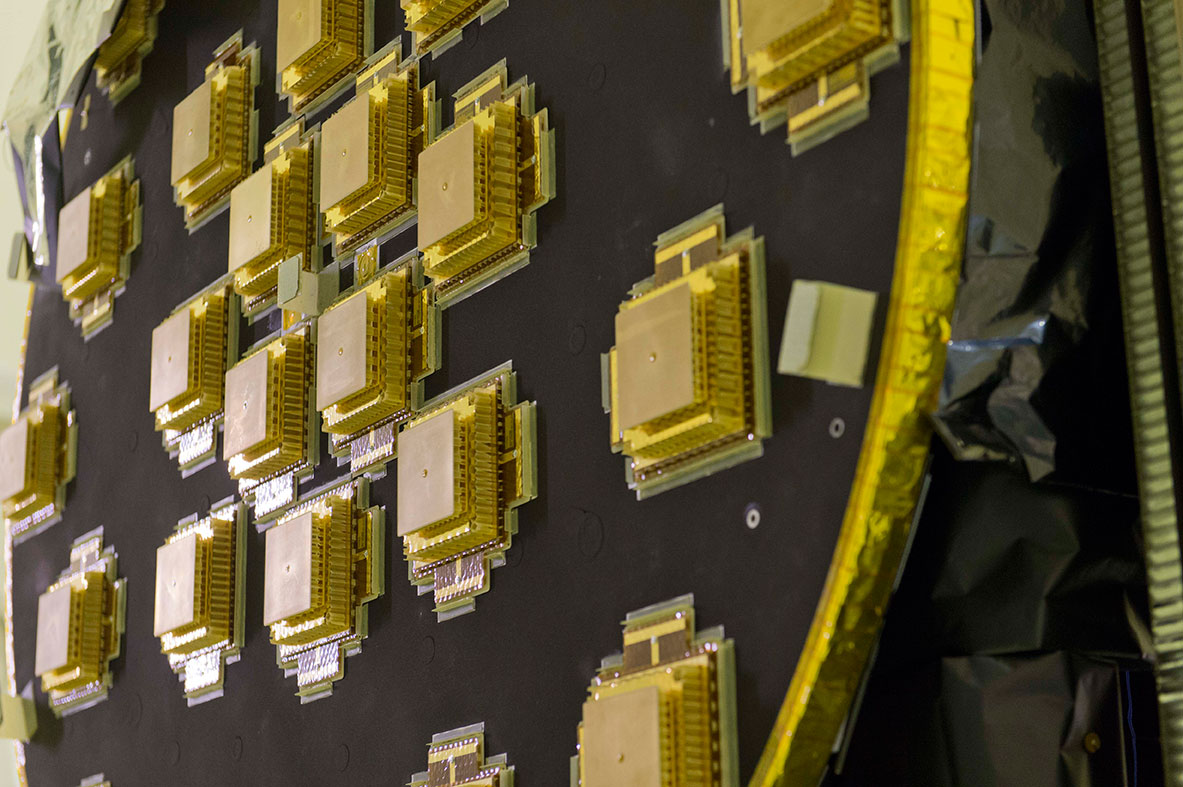
The main antenna of the second Galileo Full Operational Capability (FOC) satellite being inspected with a flashlight in advance of mass property testing during August 2013.
Europe’s next pair of Galileo satellites have been the focus of a busy autumn at the European Space Agency’s (ESA’s) technical centre in the Netherlands, continuing a full-scale campaign to ensure their readiness for space.
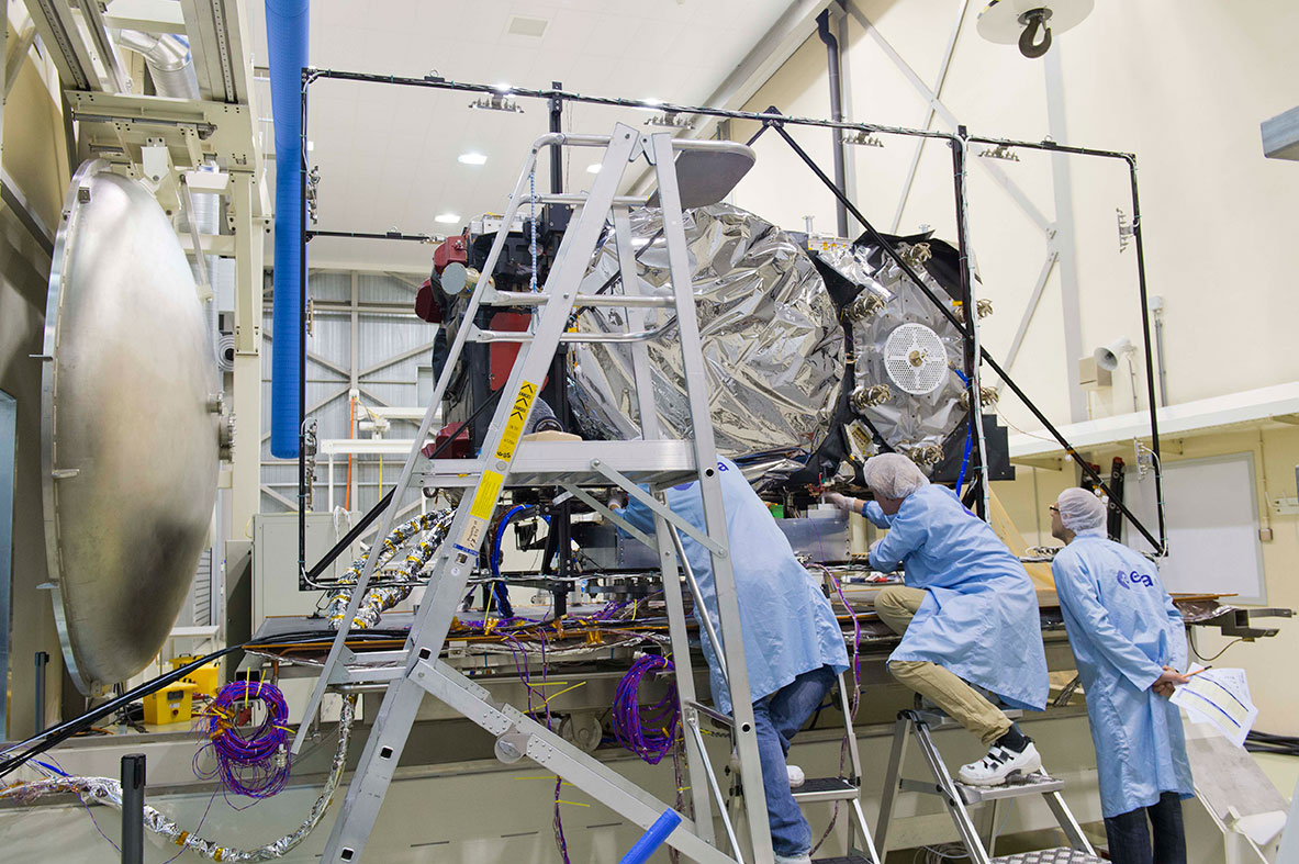
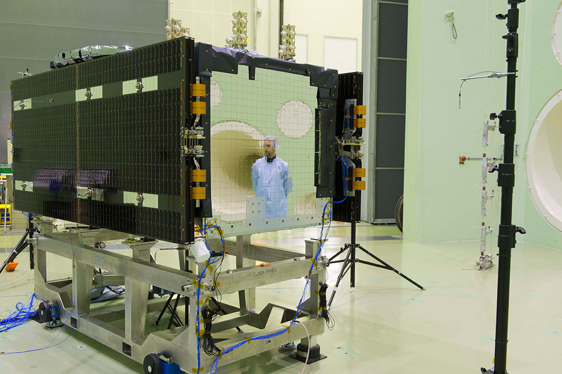
The first Galileo Full Operational Capability (FOC) satellite, FM1, seen beside the Phenix test chamber being readied for its five-week long thermal vacuum testing in October 2013.
With the first four Galileos already in orbit, these new versions are the first two of a total 22 Full Operational Capability (FOC) satellites being built by OHB in Germany with a payload from Surrey Satellite Technology Ltd. in the UK.
The second satellite joined its predecessor in mid-August at ESA’s European Space Research and Technology Centre in Noordwijk. This is the largest spacecraft testing site in Europe, with a full range of space simulation facilities under a single roof in cleanroom conditions. A wide range of tests have been performed on the two satellites.
The first of the two satellites is now midway through a five-week immersion in vacuum and temperature extremes that mimic the conditions it faces in space. This thermal-vacuum test takes place inside a 4.5-meter diameter stainless-steel vacuum chamber called Phenix. An inner box called the thermal tent has sides that are heated to simulate the Sun’s radiation or cooled down by liquid nitrogen to create the chill of Sunless space.
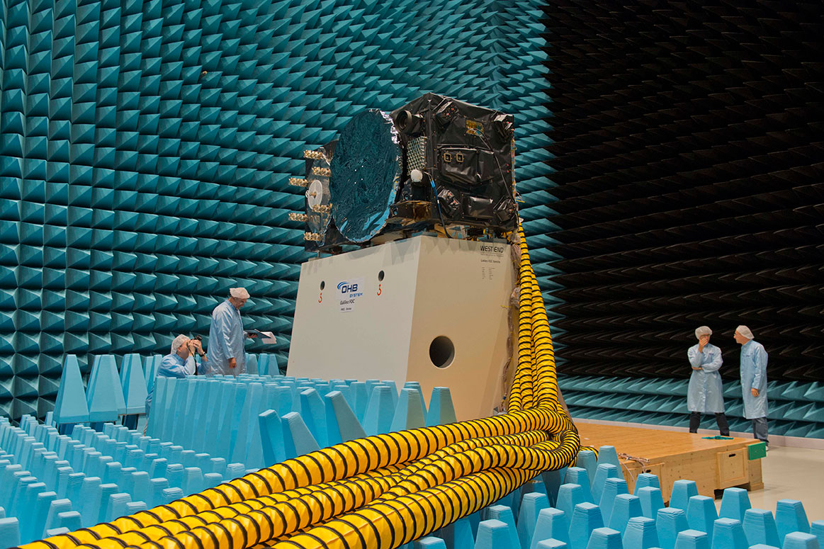
Second Galileo Full Operational Capability (FOC) satellite being prepared for acoustic testing, simulating the noise of a rocket launch, inside the Large European Acoustic Facility, LEAF, of the ESTEC Test Centre in early September 2013.
The newly arrived satellite first underwent a mass property test — measured to check its center of gravity and mass are aligned within design specifications. The more precisely these are known, the more efficiently the satellite’s orientation can be controlled with thruster firings in orbit, potentially elongating their working life by conserving propellant.
Meanwhile, its predecessor left the wider universe behind in the Maxwell Test Chamber. Shielded walls blocking out all external electrical signals and spiky, radio-absorbing anechoic material lining the chamber enable electromagnetic compatibility testing. Isolated within the chamber as though floating in infinite space, the satellite could be switched on to check all its systems can operate together without interference.
September saw the second satellite undergo acoustic testing in the Large European Acoustic Facility, LEAF, effectively the largest sound system in Europe. The first satellite submitted to this trial just a few weeks before. A quartet of noise horns are embedded in one wall of this 11-meter-wide, 9-meter-deep and 16.4-meter-high chamber, generating sound by passing nitrogen gas through the horns, surpassing 140 decibels.
Galileo Full Operational Capability (FOC) satellite first flight model, FM1, being prepared for ‘passive intermodulation testing’ within the Maxwell electromagnetic test facility inside the ESTEC Test Centre at the end of August 2013.
Accelerometers placed within the satellite checked for potentially hazardous internal vibration during this trial by sound. Then the spacecraft was vibrated on the shaker tables, simulating the violent forces of a rocket launch.
Up-and-down vibration on the QUAD shaker followed by side-to-side shaking on the horizontal shaker, with data gathered across hundreds of channels.
The satellite was then connected to the dispenser that will hold it during launch to simulate the separation at the end of its climb to orbit. This separation is triggered by firing a pyro device which then pushes the satellite away from the dispenser. This demonstration took place last month.
“There will always be two Galileo satellites being tested at the ESTEC Test Centre for the next few years,” explains Giuliano Gatti, the head of the Galileo Space Segment Procurement Office.
“As the Galileo constellation takes shape, ESTEC will remain an essential part of each satellite’s pathway to space, between the end of manufacturing in Germany and UK and the launch by Soyuz ST-B or Ariane-5 from Europe’s Spaceport in French Guiana.
“Of course, the testing on these initial FOC satellites is especially rigorous because we are validating the overall design. The Galileo satellites to follow will undergo more streamlined ‘acceptance’ testing instead.”
The next two satellites are in final assembly at OHB in Germany, scheduled to reach ESTEC early next year, as these first two satellites head off to French Guiana for launch.
Galileo Full Operational Capability Flight Model 2, FM2, satellite’s main L-band antenna used for broadcasting navigation messages, seen during preparation for a mass property test at the ESTEC Test Centre at the end of August 2013.
Kipo, a GPS mobile location technology company targeting businesses and families, and Tigo Business Guatemala, a telecommunications company, announced their partnership to launch Localizador Tigo. Localizador Tigo is a smart, user-friendly location platform that allows any type of mobile device to connect to the web and trigger actions by predetermined rules, the companies said.
Triggers include location (arrival, exit, stay) and device events such as battery consumption and speed. Rules determine how the event will trigger and the action to take — send an email, post on social networks, mark a calendar, send an SMS, among others. For example, a company can create a rule that notifies a manager when his messenger delivers paperwork. Every time the messenger arrives to a specific location, the manager would receive an automatic email from the software. The sales manager could also create a rule to identify every time the sales team members have less than 10 percent battery. Once a device runs low on battery the manager would receive an automatic SMS to his mobile device.
The technology also lets team members check in and leave comments when they arrive with clients, information that can be seen in real-time on the web alongside a complete suite of reports to make cell phone devices more useful than ever before. The product can work with any mobile device — smartphones will be able to access the service through native applications and feature phones will rely on cell-towers to report location.
Localizador Tigo gives customers full ownership and control over their data and eliminating contracts, giving them the liberty to cancel service at any time. The product will be launched initially for corporate clients of Tigo Business and will be offered to individual customers on a later phase.
“We believe GPS location technology should be smarter and easier to use. This alliance with Tigo Business makes real-time GPS technology accessible to millions of Tigo customers, which is great because we are allowing more people than ever before receive the benefits this technology provides,” said Rodrigo Blanco, founder and co-CEO of Kipo, Inc.
“In Tigo Business we are always looking to provide our clients with the best and the most advanced tools so they can operate efficiently. We had been searching globally for the leading geolocation platform to incorporate to our mobile devices, and to our surprise we found it in a Guatemalan startup. The Kipo platform is functional, targets the needs of Tigo Business clients and is easy to use. The partnership with Kipo is a perfect next step to continue innovating and offering preeminent products to our clients,” said Hector Jimenez, category manager of Tigo Business Guatemala.
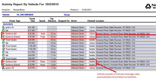
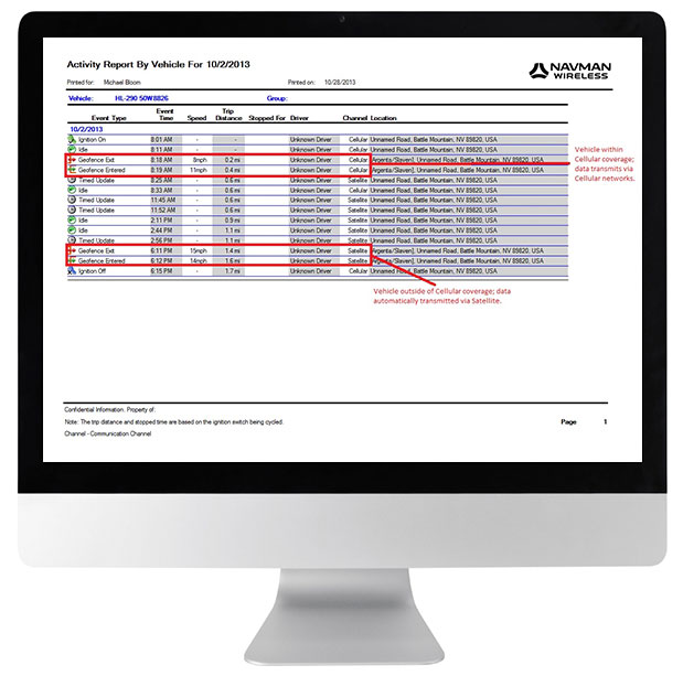
Navman Wireless USA today announced a new satellite communications option for its OnlineAVL2 fleet tracking platform, enabling continuous visibility of both heavy equipment and on-road vehicles even when assets are out of cellular coverage. Designed for construction, surface mining, mining and oil and gas exploration, and other environments with remote location work, the new solution includes the ability to minimize data charges by transmitting only the most critical event information via satellite.
Satellite connectivity is provided via a small modem that plugs into the serial port on Navman Wireless’ Qube on-highway or ruggedized Qtanium off-highway GPS tracking devices. The system automatically switches between cellular and satellite transmission with intelligent least-cost routing, using the global Iridium satellite network when fleet assets move out of cellular range. Benefits include:
Uninterrupted real-time fleet tracking without losing visibility of equipment location and other status information when assets are beyond the reach of cell towers.
Increased employee safety because equipment and vehicles are never out of sight of the fleet tracking system, even if they are working in cellular dead zones.
No missed engine alerts, potentially preventing costly machine repairs and downtime by ensuring that job supervisors are promptly informed when engine, coolant, transmission or air filter sensors connected to GPS tracking devices exceed pre-defined thresholds.
Cost-saving configurability, with the option to limit satellite transmissions to priority events (panic messages, rollover alerts, engine overheating, speed or geofence violations, etc.) and delay the transfer of low-priority event data until cellular coverage is restored.
“If a machine or vehicle in your fleet is operating outside of cell coverage and you have critical communications that need to take place for safety or operations reasons, it can be a problem to wait until the asset gets back into cell range,” said Davis Gammage, VP Product Management, Navman Wireless. “Temporarily switching to satellite communication solves the problem and ensures 100% visibility of your equipment as well as your field staff.”
The new satellite communications option marks the latest expansion of Navman Wireless’ fleet tracking portfolio for the construction, mining, and oil and gas industries. The company’s OnlineAVL2 fleet tracking platform provides location, operations and performance data for both on-highway vehicles and construction heavy equipment from a single interface. The back-end OnlineAVL2 application — delivered under the software-as-a-service model — includes industry-specific reporting such as jobsite utilization reports that break down equipment use by project, facilitate proper cost accounting, reduce writeoffs for unallocated asset hours, and aid in the development of future job bids for construction customers.
In the field, capture up to 200 MHz of multi-channel bandwidth and return to your lab with a rich library of GPS and GLONASS signals and impairments to accelerate RF product designs and research. Add a camera for a complete view and map of your recording environment.
Averna’s RF Studio software and suite of award-winning RF test instruments set the standard for portability, flexibility and repeatability, empowering you to efficiently record and play back all common radio, video, and GNSS signals in the highest fidelity to accelerate RF projects and reduce travel and testing costs.
RF Studio: A Powerful Software for Easy RF Recording
Available with Averna’s RF recorders and for National Instruments’ USRP, the versatile RF Studio features signal templates for quick setup and recording. With the Noise Figure feature you can view and record weak signals under the noise floor, and with the Spectrum, Power, and Histogram views you can visualize and analyze all your captured RF spectrum.
With the optional DriveView™ module, you can capture a complete visual record and map of where you made your recordings to aid analysis and troubleshooting. As well, RF Studio’s plug-in architecture supports additional hardware, channels, user inputs, remote triggering and a distributed control interface to ensure the widest possible application.
RF Studio is available with the following platforms
National Instruments’ USRP
RF Studio for the USRP is the only product on the market in its price range that offers the flexibility to cover a wide variety of use cases, thus making it a very competitive solution for general-purpose RF R&P. RF Studio gives NI USRP customers a turnkey RF R&P solution while also leveraging the flexibility and customization possibilities that have made this software-defined radio such a successful platform.
Averna’s RF Record & Playback Solutions
Our suite of RF test instruments sets the standard for portability, flexibility and repeatability, empowering RF device manufacturers to efficiently generate, record and play back all common radio, video, and navigation signals, ensuring complete test coverage and the highest quality for their RF products.
Multi-Channel, 50 MHz and 20 MHz Compact RF Recorders
Since 2007, the worldwide scientific community has met every two years to discuss the possibilities for boosting the scientific use of Galileo and for contributing to the development of the GNSS.
The event is always organized in one of the 20 European Space Agency’s Member States, and makes an essential contribution to ESA’s implementation and definition of the evolution of the European GNSS. The gathering of major academic players provides a scientific reference for institutional executives and industry, as well as offering a unique platform for promoting innovative GNSS initiatives at large.
The colloquium focuses on four major areas of research:
Scientific applications in meteorology, geodesy, geophysics, space physics, oceanography, land surface and ecosystem studies, using either direct or reflected signals, differential measurements, phase measurements, radio occultation measurements, using receivers placed on the ground, in aircraft or on satellites.
Scientific developments in physics, dealing with future GNSS, particularly in testing fundamental laws in astronomy and in quantum communication. Relativistic reference frames and relativistic positioning will be addressed.
Aspects of metrology such as reference frames, onboard and ground clocks, and precise orbit determination.
Scientific aspects of satellite navigation and positioning such as signal propagation, tropospheric and ionospheric corrections and the means to model and mitigate multipath and interference.
The various possibilities to use navigation satellites such as Galileo for scientific purposes will be reviewed and the use of scientific applications to contribute to make the most of the present systems and define their evolution will be scrutinized.
The conference is being organized as a series of plenary talks and two parallel half-day sessions.
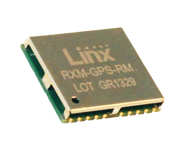
Linx Technologies announces its launch of the high-performance, low-cost RM GPS receiver modules. Using the built-in MediaTek MT3337 chipset, the RM module can simultaneously acquire on 66 channels and track on up to 22 channels, providing standard NMEA data messages through a UART interface. A simple serial command set can be used to configure optional features.
According to the company, the RM receiver module is a cost-effective GPS solution that offers no-frills, basic operation in a compact 15 x 13 millimeter package. The MediaTek MT3337-based RM Series is self-contained and only requires an antenna. It powers up and outputs position data without any software set-up or configuration, making the RM Series easy to integrate, the company said.
The receiver operates down to 3.0 volts and has a low tracking current of 12mA. The module has built-in receiver duty cycling that can be configured to periodically turn off the module for added power savings. This low-power consumption helps maximize runtimes in battery powered applications, such as consumer recreational positioning, marine, location and tracking, cargo tracking, and other asset monitoring systems.
In addition, the available GPS Master Development System connects a RM Series Evaluation Module to a prototyping board with a color display that shows coordinates, a speedometer and compass for mobile evaluation. A USB interface allows simple viewing of satellite data and Internet mapping, as well as custom software application development.
ABI Research forecasts that the global market for Driver Monitoring Systems (DMS) will reach 64.8 million units by the end of 2020 with the majority of shipments being accounted for in vehicles sold in the Asia-Pacific region. These findings are part of ABI Research’s Intelligent Transportation Systems Research Service and includes detailed installed base and forecasts of ADAS systems [advanced driver assistance systems] by regions.
Driver Monitoring Systems were first introduced as far back as 2006 when Toyota launched its innovative Driver Attention Monitor system. Toyota’s system functions by directly monitoring the driver’s face using a discrete in-dash camera and was initially offered as an option in the company’s luxury Lexus models. Other OEMs soon followed suit and announced their own DMS systems which were typically based on monitoring the vehicle rather than the driver’s face.
“DMS systems such as Mercedes-Benz’s ’Attention Assist’ and Volvo and Volkswagen’s ’Driver Alert’ systems were the first ADAS systems to be offered as standard equipment by OEMs, albeit only in a small selection of models,” comments Gareth Owen, principal analyst at ABI Research.
Today, an increasing number of ADAS systems are gradually becoming standard equipment in new cars, particularly in some European and Japanese brands such as Volvo, Mercedes-Benz, Nissan Infiniti, Lexus, and Mazda, and more are being offered as options. Although some of the big U.S. brands offer ADAS features in their European models, they typically do not offer the same features in their U.S. models, although this is beginning to change. Ford is a good example of this with its Ford Focus model.
“Another very observable trend in 2013 is that ADAS features are migrating from the luxury brands into B, C, and even A segment cars. Typically, the focus here is on offering ADAS systems, mostly as options, designed specifically for low-speed urban driving,” adds Owen.
Prices are decreasing, too. For example, the European Ford Focus offers an emergency braking system plus lane departure warning and lane-keep assist, driver alert, and blind spot monitoring as an optional package for £550 ($880) in the UK. Meanwhile, Volkswagen offers its City Emergency Braking System for £225-£405 ($360-$648), depending on model, on its budget A segment Up! car. This uses a laser sensor to detect the risk of an imminent collision and is active at speeds under 30 km/hr (18 mph).
Northrop Grumman Corporation is applying a modular, open architecture approach throughout its product portfolio, allowing for rapid addition of new avionics capabilities for warfighters. Northrop Grumman is already applying the FACE Reference Architecture and interfaces to existing programs and products, including an embedded GPS/inertial navigation system for the Joint Precision Approach and Landing System and a highly adaptable mission equipment package.
Northrop Grumman will leverage the corporation’s expertise in open architecture to implement FACE requirements for both current and future programs, including the Black Hawk H-60L Digital Performance Plan program and Tech-Refresh Mission Computers for the H-1 Upgrade program.
The company plans to participate in demonstrations that will promote maturation of the FACE Reference Architecture by enabling companies to deploy their products in a functional, standardized FACE software environment.
Also, the company’s Transport Services Segment aligns with the FACE Technical Standard requirements and provides a standard interface that allows portable avionics applications to be integrated with a variety of architectures and aviation platforms.
“An open architecture approach is critical to the affordability, innovation and effectiveness of avionics systems,” said Ike Song, vice president of Northrop Grumman’s Situational Awareness Systems business unit. “We are using performance-proven solutions from across our corporation to offer highly flexible, affordable products that support reuse on various platforms.”
Northrop Grumman’s Common Mission Management System (CMMS) establishes a common foundation for affordable control systems to support a variety of the company’s unmanned products. Based upon open architecture standards and standard off-the-shelf commercial hardware and software infrastructures, the Northrop Grumman CMMS product line avoids the need for dedicated, custom-built command and control systems for individual platforms. Also, the Northrop Grumman CMMS product line enables pilots to operate a variety of dissimilar unmanned platforms using the same informational displays and control features, thereby improving mission effectiveness while reducing training requirements.
With its expertise in unmanned aerial systems (UAS), the Northrop Grumman team was instrumental in leading the FACE Consortium’s effort to align with the UAS Control Segment (UCS) information model, establishing a common conceptual data model and metamodel as a framework that defines rules and conventions for developing interoperable software components for unmanned aerial system ground control stations. Further collaboration under the UCS/FACE Memorandum of Agreement is anticipated in aligning the FACE and UCS standards.
Northrop Grumman is a leading global security company providing innovative systems, products and solutions in unmanned systems, cyber, C4ISR, and logistics and modernization to government and commercial customers worldwide.
The annual Intergeo conference and trade fair, this year held October 8–10 in Essen, Germany, elicited three principal observations from the three GPS World staff who attended:
Unmanned aerial vehicles, particularly in micro-form factor, have exploded across multiple sectors of the industrial economy. Emulating GPS — and carrying GPS on board in most cases — UAV has become an enabling technology with far-reaching implications.
Mobile devices bearing GPS/GNSS have likewise exploded, with many more commercial makers and models of handheld survey/mapping devices and location-enabled tablets to be found in Europe than in the United States.
GNSS manufacturers from China are making major efforts to secure distributors and break into the international market. Several had substantial booths, noticeably larger than the fewer, smaller booths present at Intergeo 2012.
Like ION-GNSS+, Intergeo spans an industrial exhibit and a technical conference, but the emphasis in Germany is decidedly on the former.
The technical conference covers key topics from a geoinformational perspective: environment, climate, energy, disaster management, cartography, spatial data, land policy, geographic information systems (GIS), and satellite processes and geodesy. About 140 presentations in 40 subject areas drew 1,300 participants — slightly larger than ION-GNSS+.
But the real story here is the gigantic trade fair for geodesy, geoinformation, and land management, displaying GIS software and services, surveying equipment and accessories, data capture and processing, remote sensing photogrammetry, cartography, and much more — including a dizzying and frequently buzzing array of micro-UAVs.
These face less regulation Europe than in the United States, which has still to come to grips with the technology. Federal Aviation Administration rules are expected in 2015.
The 28,000 square-meter Intergeo exhibition space featured 505 exhibitors from 30 nations and drew an estimated 16,000 attendees from 80 countries — making it between eight and 125 times the size of the ION GNSS+ industry exhibit. Clearly, the German show has a different mission and a different mix of both exhibitors and attendees, spanning different bands of the GNSS application spectrum; and, its orientation is much more commercial.
Exhibitors at the two shows form sort of an old-fashioned Venn diagram: some exclusive to either show and some overlapping, appearing at both. Among the latter group were: JAVAD GNSS, Trimble, Hemisphere GNSS, Leica Geosystems, NovAtel, Septentrio, ComNav Technology, Topcon Positioning Systems, and Fraunhofer Institute.
Among GNSS companies showing in Essen but not in Nashville were Altus Positioning, AllSat GmbH, Carlson Software, CHC Navigation, Forsberg, Fugro Geospatial, and Hi-Target.
A final question proffers itself after three days amid this hubbub: Why is there not a North American show of this nature? The Esri User Conference comes closest, but it is vendor-specific. There would appear to be a niche for a 5,000–10,000 attendee tradeshow in this sector.
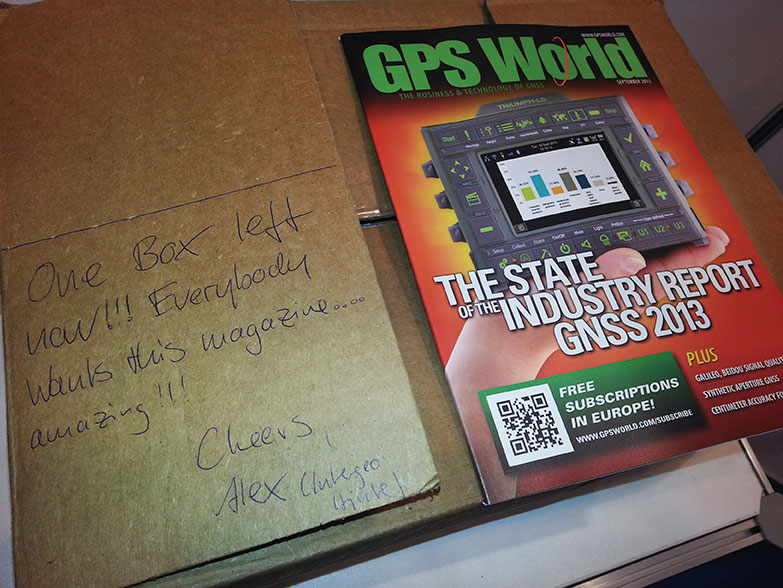
GPS World shipped 700 copies of the September issue to Intergeo; by the second morning of the three-day show, nearly all were gone, as attested by this note from our friendly bin stocker. Publisher Alan Cameron, Survey/GIS Editor Eric Gakstatter, and Associate Publisher Steve Copley attended, holding productive meetings with many exhibitors.
Russian scientists propose a new code-division multiple-access signal format to be broadcast on a new GLONASS L3 signal. Once implemented across the modernizing GLONASS constellation, this will facilitate interoperability with — and eventually interchangeability among — other GNSS signals. The flexible message format permits relatively easy upgrades in the navigation message, if required.
By Alexander Povalyaev
Navigation messages (NM) developed and broadcast so far, by both GPS and GLONASS, are fixed, regular structures including pages (frames), subframes (rows), and words. Despite their simplicity, such structures are very conservative. The only possibility to update such navigation messages is restricted to the use of previously allocated backup frames. Increasing numbers of such frames make for ineffective use of navigation message transmission capacity. Conversely, the relatively small number of backup frames restricts the potential for future navigation-message upgrades.
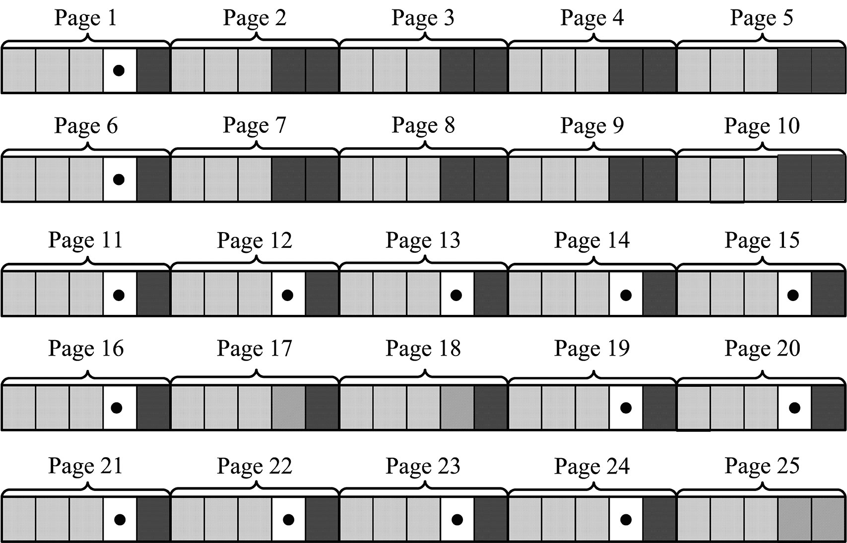
This concept is illustrated by the next two figures. Figure 1 shows the structure of GPS NM superframe.nBackup subframes are showed in bold dots. We can see that from 125 subframes of a GPS NM with a duration of 12.5 minutes, 14 subframes (or roughly 11 percent) are backup ones.
Figure 1. Backup of GPS NM superframe.
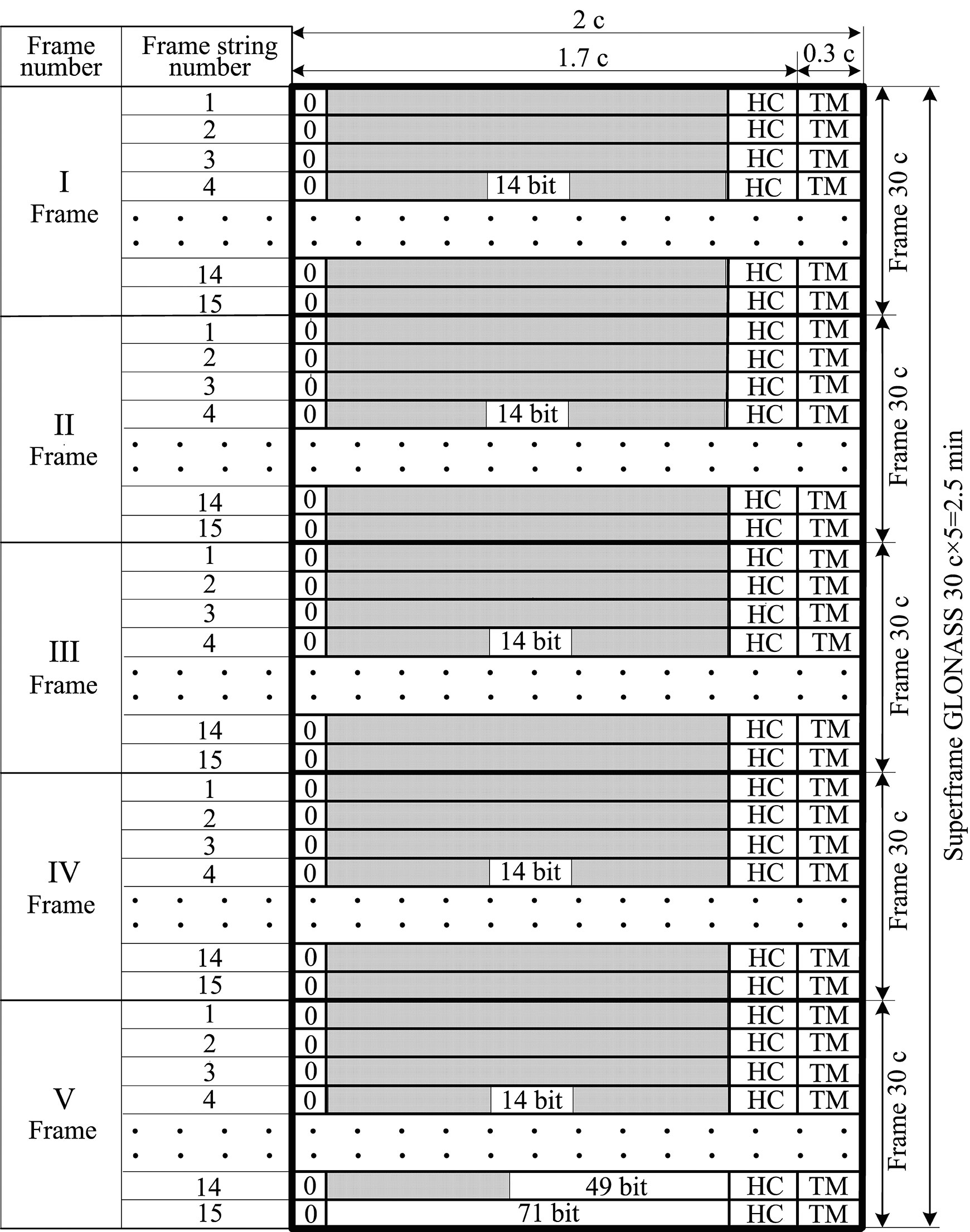
Figure 2 shows the structure of GLONASS NM. Backup frames with indication of bit numbers are shown by unhatched fields. In the GLONASS superframe with a duration of 2.5 minutes, these bits occupy only about 3 percent.
If we assume a data equivalence transmitted in the GLONASS and GPS navigation solutions, we can see that data transmission rate in GLONASS is five times as much as in GPS. This is explained by the higher redundancy of the GPS NM. Besides the roughly 11 percent of subframes kept in backup, the GPS superframe reserves field for transmission of 32 satellite almanacs, although the number of satellites in GPS constellation is always less than 32. As a result, the NM transmission channel in GPS used ineffeciently.
For GLONASS, the situation is different. The NM includes only about 3 percent of backup bits, and the superframe reserves field for transmission of only 24 satellite almanacs. This significantly increases the NM transmission channel efficiency relative to GPS, but causes big problems during any process of system update.
In these cases, upgrades or updates should only occur when they furnish backward compatibility, which means that previously manufactured user equipment can still maintain its compatibility with the updated system. When generating a NM in the form of fixed, strictly regular structures including pages (frames), subframes (rows), and words meeting the backward compatibility principle, this means that update sonly can be done using backup frames, because modification of basic, non-redundant frames will produce problems with earlier user equipment health. From this point of view, a large number of backup frames in very preferable.
Difficulties. As an example, let us consider the problems that arise in the process of a GLONASS upgrade, the purpose of which is to increase the number of GLONASS satellites in the constellation up to 30. Such an upgrade can be done in order to exclude areas of dilution of precision (DOP) degradation that arise due to GLONASS’s symmetrical constellation geometry. To provide that the rule of backward compatibility is met, it is necessary that almanacs of six extra satellites be placed in backup bits of the superframe. But the number of such bits in the GLONASS superframe (as shown in Figure 2) allows placement of only one satellite almanac. Thus in the case of such an upgrade, the almanac of the first basic 24 salellites will be transmitted within the time of 1 superframe, that is, 2.5 minutes, and the almanac of the xis extra satellites will be transmitted consequently in backup rows within the time of six superframes, that is, 2.5 × 6 = 15 minutes.
Figure 2. Backup of GLONASS navigation message superframe.
A New Way. Avoiding such difficulties associated with NMs with fixed, strictly regular structures including pages (frames), subframes (rows), and words is possible through the use of a NM with flexible row structure. Such a structure was formed for the first time for the GPS L5 signal. In this structure, the NM is formed as a variable-row flow of different types. Each row type has a unique structure and contains specified information type, for example: ephemeris, almanacs of specified satellites, parameters of Earth pole movement models, parameters of ionosphere delay models, and so on.
User equipment allots a successive row from the flow, defines its type, and in accordance with the type allots data contained in this row. When using such NM structure, strict regularity of different data types received by user equipment is disturbed, but GNSS control system guarantees that data transmission delays for each data type in NM will not exceed maximum values previously defined in the interface control document (ICD). For example, rows with ephemeris data in the GPS L5 signal are transmitted a minimum of once every 24 seconds, the so-called restricted almanac of the system is transmitted minimum once every 10 minutes, and so on. (See the “Navstar GPS Space Segment/User Segment L5 Interfaces, IS-GPS-705,” www.navcen.uscg.gov/pdf/Number.pdf.)
Deploying a Growing GNSS. A flexible row structure of the NM provides more effective use of NM transmission channel capacity, especially during the stage of system deployment which, as experience has shown, may last several years. During this stage, the GNSS orbital constellation is not complete and thus the NM may be generated as a row flow containing almanacs of only those satellites that are actually included in the orbital constellation. Reducing the number of rows with satellite almanacs allows reducing the time interval per which ephemeris are transmitted. Obviously a NM with fixed regular structures does not permit this capability.
The main advantage of a NM with flexible row structure is the possibility of its evolutional upgrade meeting the rule of backward compatibility. For this purpose, the ICD of respective signals for developers of user equipment states that if the user equipment encounters unknown row types, it should ignore them. This allows adding new row types in the process off GNSS upgrade. Including rows of new types in the NM certainly lowers the transmission rate, relative to rows of old types.
Previously manufactured user equipment ignores rows with new types and therefore does not use innovations introduced in the process of GNSS upgrade, but at the same time its health is not affected. More recent user equipment gets the opportunity to use data both from old and new row types and therefore to use introduced innovations.
In this case, user equipment upgrade replaces old software versions with new ones. This replacement is not due to any invalidity of old software version, but the equipment owner’s desire to benefit from the innovations introduced by GNSS.
Very old row types may on the other hand be removed from NM. At that point, very old and not-upgraded user equipment would become non-operational. This situation is quite normal because it may be considered as excluding excessively obsolete user equipment from operation.
When using flexible row structure, a GLONASS NM upgrade as in the previous example on exceeding the number of satellites up to 30 would mean simply exceeding the number of rows with the type defining the structure of almanac data. In this case, transmission rate of ephemeris and almanac would certainly degrade a little, but it would require no conversion of user-equipment software.
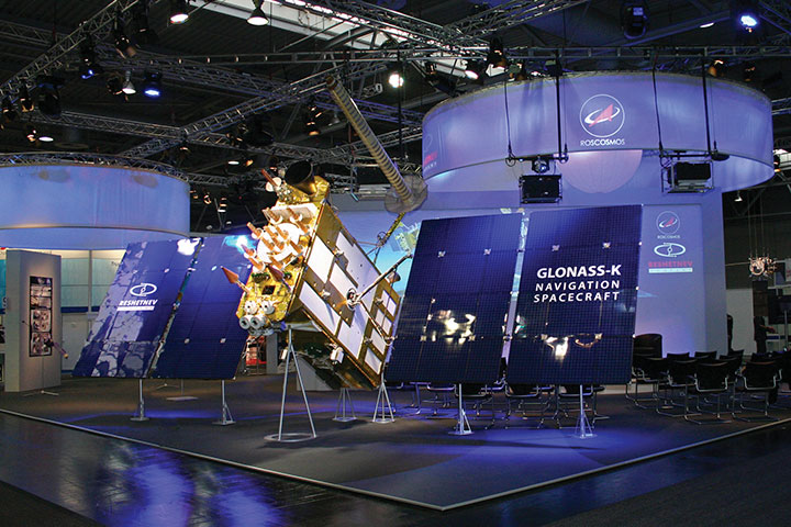
Status. Currently GLONASS uses signals with frequency separation in L1 (1592.9 – 1610 MHz) and L2 (1237.8 – 1256.8 MHz). The system upgrade now underway will in the long-range outlook turn to signals with code-division multiple-access (CDMA) in L1, L2, and L3 (1190.35 – 1212.23 MHz). One satellite has been launched transmitting signals with code separation in L3.
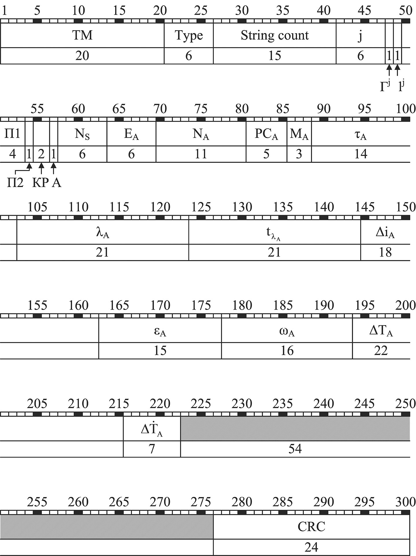
The NM of all new GLONASS signals with code separation, or CDMA, will have flexible row structure. Documents are now being developed concerning NM row structure of this type. For example, Figure 3 shows the structure of 20throw type for open signal L3OC with code separation in L3 containing almanac. L3OC signal rows contain 300 bits and have time interval of 3 seconds.
Figure 3. The structure of 20th row type for GLONASS open signal L3OC with code separation.
Parameters shown in Figure 3 have the following meaning:
TM time mark signal Type row type (in this case = 20) String count time mark numeralization; j number of satellite transmitting present NM Гj health operative feature («0») or unhealth operative feature («1») of satellite j navigation radiosignal lj reliability feature («0») or unreliability feature («1») of NM data in the current row with number j; П1 service bits for calling ground control system (НКУ) П2 satellite orientation mode feature: П2 = 0, satellite is in orientation mode to the Sun; П2 = 1, satellite is in the mode of anticipatory turn or in the mode change status (Sun orientation and anticipatory turn) КР feature of planned correction of onboard time scale (OTS) by ± 1 sec at the end of Greenwich current quarter А anomaly feature of the following row which, when onboard time scale has been corrected by ± 1 sec, will have 2 or 4 sec CRC control bits of cyclic redundancy code.
The above parameters of 20th row type are service parameters. Their content remains unchanged for all NS rows of L3OC. The following parameters of 20th row type are information parameters. Ns the number of satellites in the current constellation EA satellite almanac age NA calendar day number within 4-year interval to which almanac belongs РСA status register of navigation radiosignals L1, L2, L3 MA satellite upgrade with the number j τA correction for transition from OTS of the satellite with number j to GLONASS time scale (GTS) λA geodetic longitude of the first ascending node of the satellite orbit with number j within the day with number NA tλA the time (according to the Moscow decree time) when the satellite with the number j transits the first ascending node within the day with number NА ΔiA correction to the orbit inclination average value (63º) for the satellite with the number j εA satellite orbit eccentricity with the number j ωA satellite orbit perigee argument for the satellite with the number j ΔTA correction to average value (43,200 seconds) rate of change of Zodiacal orbital period for the satellite with the number j ΔTA Zodiacal orbital period for the satellite with the number j.
Acknowledgment
The author would like to thank Sergey Karutin and Dmitry Lerner for help in translation of this paper.
Alexander Povalyaev is deputy head of division in JSC Russian Space Systems and a professor at the Moscow Aviation Institute. He has been developing methods and algorithms for GNSS carrier-phase measurements processing for more than 30 years. Currently he focuses on developing new code-division GLONASS signals.
The Business section of the November 2013 issue of GPS World (Download the PDF).
Focus on Timing
Includes: Orolia to Supply Atomic Clocks for Galileo Satellites; Symmetricom Expands SyncWorld Program to Power Utilities; Product Showcase. Plus: NextNav and Broadcom Partner for Indoor Accuracy; Events.