Author: GPS World Staff

  • Connor-Winfield Offers GPS-Disciplined Clock

    Connor-Winfield Offers GPS-Disciplined Clock

    Connor-Winfield-FTS500-W
    The FTS500 Xenith TBR

    The FTS500 Xenith TBR (Time Base Reference) by Connor-Winfield is designed for DVB/DAB, wireless communications, time-stamping, or any other timing vital application.

    The Xenith TBR module is a GPS-driven, mixed-signal phase lock loop, providing a 1PPS CMOS output and generating a 10-MHz SINE output from an intrinsically low jitter voltage controlled crystal oscillator (VCXO). The 10-MHz output is disciplined from an on-board GPS receiver, which drives the long-term frequency stability. Its on-board CW25 timing GPS receiver along with a dual-oven system provides the highest quality timing and synchronization signals combined with superb hold-over characteristics. The unit is housed in a 106 x 125 x 56 millimeter strong aluminum enclosure.

  • GPS Sensor

    GPS Sensor

    CW46S-ConnorWinfield-W
    The CW46S GPS sensor by NavSync.

    The CW46S GPS sensor by NavSync is a fully integrated module that includes a CW25 GPS receiver, DC/DC converter, RS232 or RS422 interface options, and active GPS antenna housed in a small weatherproof (IP67-rated) enclosure.
    When mounted with a good sky view, the CW46S receiver can provide high-quality timing and synchronization. The 1 pulse per second (PPS) timing signal can provide accuracies to within 30nS RMS of Coordinated Universal Time (UTC).

    The 1PPS is transmitted via RS422 signal format; this two-wire method allows the pulse to be transmitted with cable lengths exceeding 100 meters.

    The CW46S utilizes the CW25­TIM GPS receiver, which allows the CW46S to act as a complete timing module capable of outputting a GPS-disciplined 10-MHz frequency.

  • The System: Autumn Falls Back

    The System: Autumn Falls Back

    Delta IV, the current GPS launch vehicle, awaits a date with space at Cape Canaveral.
    Delta IV, the current GPS launch vehicle, awaits a date with space at Cape Canaveral.

    Launch Delays Ground GPS IIF and Galileo FOC

    The scheduled October 23 launch of GPS IIF-5, the fifth in the current “follow-on” generation of GPS satellites, has been postponed in order to complete a review of an adjustment made to the rocket’s upper stage engine. A loss of thrust by a Delta IV rocket upper stage during a GPS launch last year worried the Air Force and the United Launch Alliance (ULA), though the satellite successfully reached its intended orbit.

    A subsequent  investigation identified a fuel leak in the engine system as the culprit. Two  medium Delta IV rockets and one heavy version have launched since then, but ULA said further investigation had produced new information about the engine’s first start.

    While no new launch date has been set, the ULA released a statement:

    “The ongoing Phase II investigation has included extremely detailed characterization and reconstructions of the instrumentation signatures obtained from the October 2012 launch and these have recently resulted in some updated conclusions related to dynamic responses that occurred on the engine system during the first engine start event.

    “The GPS IIF-5 Delta IV launch is being delayed to allow the technical team time to further assess these updated conclusions and improvements already implemented and determine whether additional changes are required prior to the next Delta IV launch.

    “The Delta IV booster for the GPS IIF-5 mission has completed the standard processing and checkout on the launch pad and will be maintained in a ready state for spacecraft mate and launch pending completion of this assessment. A new launch date will be established when the assessment of the updated dynamic response information is completed in the coming weeks.”

    A Soyuz rocket (right) will carry Galileo FOC satellites, but no sooner than June 2014.
    A Soyuz rocket (right) will carry Galileo FOC satellites, but no sooner than June 2014.

    Galileo. Continuing delays in ground testing of the first two fully operational Galileo satellites have postponed their launch to June 2014 at the earliest.

    According to European officials, the European Space Research and Technology Centre (ESTEC) thermal vacuum chamber for testing satellites under orbit conditions was not ready for the two FOC satellites delivered by OHB in late summer.

    The satellites thus cannot ship to the Guiana spaceport in South America in time for a planned 2013 launch on a Soyuz rocket. The Galileo schedule is also running into bottlenecks with scheduled launches by other satellite programs aboard Guiana Soyuzes.

    A six-week test of the first Galileo satellite at ESTEC reportedly got under way in October.

    Svalbard station on Spitsbergen in the Norwegian Arctic.
    Svalbard station on Spitsbergen in the Norwegian Arctic.

    Ground Network Supports Galileo for SAR

    Completion of a pair of European Space Agency dedicated ground stations at opposite ends of that continent has enabled Galileo satellites in orbit to participate in global testing of the Cospas–Sarsat search and rescue system.

    The Maspalomas station, in mid-Atlantic Canary Islands, was activated in June. In September, the Svalbard site on Spitsbergen in the Norwegian Arctic activated. The two sites can now communicate and will soon undertake joint tests.

    The International Cospas-Sarsat Programme is a satellite-based search and rescue (SAR) distress alert detection and information distribution system, established by Canada, France, Russia, and the United States, with participation by 33 other countries.

    Activation of the two new stations enables participation of the latest two Galileo satellites in a worldwide test campaign for Cospas-Sarsat expansion.
    The program is introducing a new medium-orbit SAR system to improve coverage and response times, with the Galileo satellites in the vanguard.

    The second pair of Europe’s Galileo satellites — launched together in October 2012 — are the first of the constellation to host SAR payloads. These can pick up UHF signals from emergency beacons aboard ships or aircraft or carried by individuals, which are then relayed to ground stations. There, the source is pinpointed and automatically passed on to a control center, which then routes it to local authorities for rescue.

    “The Galileo satellites, tested in combination with the same SAR payloads on Russian GLONASS satellites as well as compatible repeaters on a pair of U.S. GPS satellites, showed an ability to pinpoint simulated emergency beacons down to an accuracy of 2–5 kilometers in a matter of minutes,” explained Igor Stojkovic, ESA Galileo SAR engineer.

    “Our in-orbit validation tests so far have been in line with expectation and beyond, giving us a lot of confidence in the performance of the final system, once completed. And using a combination of satellites is just how the upgraded system will operate in practice, in order to localize distress signals.”

    Localization test performed from Maspalomas MEOLUT as part of Galileo’s SAR in-orbit validation. Beacon locations obtained with four satellites are shown in black, while those using three satellites are shown in grey. More than 93 percent of all beacon locations, after only a single beacon burst has been received, are within the required five kilometers from actual beacon position.
    Localization test performed from Maspalomas MEOLUT as part of Galileo’s SAR in-orbit validation. Beacon locations obtained with four satellites are shown in black, while those using three satellites are shown in grey. More than 93 percent of all beacon locations, after only a single beacon burst has been received, are within the required five kilometers from actual beacon position.

    System Briefs

    GLONASS Seeks UK Ground. According to the website of the Russian magazine GLONASS Messenger, the Russian Federal Space Agency communicated its proposals for specific areas in the United Kingdom (or, more likely, its territories) to accommodate stations of the GLONASS System for Differential Correction and Monitoring (SDCM). Apparently, an offer was made by the deputy head of Roscosmos, Oleg Frolov, in discussions with David Parker, the director of the British Space Agency. The desired locations for the stations will not be disclosed until the approval of their establishment by the British side, the website reported.

    Head Rolls. After repeated satellite launch failures and rumblings about embezzlement and corruption within the Russian space program Roscosmos, Vladimir Popovkin was let go as director and replaced by Oleg Ostapenko, a colonel general in the Russian Military, deputy minister of Defence, and former commander of the Aerospace Defence Forces. The Russian government also announced formation of new agency, the United Rocket and Space Corporation, to manage satellite and rocket manufacturing facilities heretofore supervised by Roscosmos.

  • Putting the (ultra-low) Power in GeoFence

    Host-Offload GNSS Positioning

    By Miguel Torroja, Steve Malkos, and Christophe Verne

    Users of smartphones, tablets, and other devices expect position with the highest level of accuracy, always available, with the least amount of power consumed. One recent improvement fulfilling this demand involves operating-system services for location on smartphones, and the evolution towards lower power solutions.

    “Please connect to a charger — The battery is getting low: less than 15 percent remaining.”

    Handsets are battery-supplied devices, and a user’s tolerance for features is driven by battery consumption. There are many examples of technologies where users do not run certain hardware or features because it will consume the battery and make the phone useless within a short period of time.

    The application processor (AP) of a handset device is very powerful, and is the part that consumes most of the battery life. Today’s smartphone multicore application processor is faster than many desktop computers that are just a few years old. Whatever the application, when it uses the AP, it can draw up to hundreds of milliamperes (mAs).

    For the last few years, the trend for GNSS has been host-based positioning. Host-based designs have less logic on the GNSS integrated circuit (IC) and employ the host AP for a portion of the positioning computation. This strategy has three advantages:

    • Shares memory and code resources with the application processor.
    • Reduces the cost of the dedicated GNSS hardware.
    • Sharing the processor makes sense since it is already running.

    Traditionally, when the GNSS solution was running, a navigation application that utilized the AP was also running.

    However, when we only want to compute GNSS positions in the background, and we do not need a third-party application running on the AP, a host-based IC architecture is not the optimal solution with regard to system power consumption. This article explains some of the technologies used to compute a GNSS position using an ultra-low power (ULP) hybrid solution that combines the classic host-based GNSS architecture with a host-offload architecture that minimizes the use of the AP.

    We discuss here two applications that benefit from a host-offload architecture: geofencing and position batching.

    We will review the requirements for a platform to support a new hybrid GNSS positioning solution. Different host-offload technologies for geofence, such as GNSS, Wi-Fi, and Cell-ID, will be compared. Broadcom’s ultralow-power host-offload GNSS solution supports any operating system. We focus here on Android’s operating system because it is the most open OS.

    Always-on Applications

    Geofencing is an application that sends reports or triggers alarms when a predefined area is crossed. For example, users can be alerted to discounts with e-coupons when walking through a mall, or to “don’t forget the milk” — users can set their own reminder notifications based off of location; also, social networking. One example of location-based reminders is through Google Keep, which uses Android’s Geofence APIs on platforms that support hardware geofencing; this application will automatically take advantage of the hardware geofence solution.

    Geofencing applications run in the background for long periods of time, and their main task is to compute positions (fixes) without the need of assistance from other applications. An ultra-low-power GNSS position solution, or always-on positioning solution, is desirable for these scenarios. Typical applications require notifications when entering or exiting a geofence area, or require periodic reporting of user positions relative to the fence.

    Geofencing is not something new. API support has been provided in mobile OS for many years, but only now can it be used without draining the battery, thanks to this new host-offload architecture.

    Figure 1 shows a circular geofence boundary and an alarm. In that example, the alarm was triggered when entering the fence.

    Figure 1. Alarm when the vehicle enters a geofence area.
    Figure 1. Alarm when the vehicle enters a geofence area.

    Breadcrumbing or position batching pertains to storing of positions, referred to as crumbs, which are accumulated for a certain amount of time and then pushed all at once to the application. Examples would be fleet or asset tracking applications, or people that wants to track their position while they are running.

    Currently, Android does not support breadcrumbing as a native feature. There is some ongoing work, and APIs are being defined.

    GNSS Positioning Models

    Before smartphones, the dominant GNSS hardware architecture employed a system-on-chip solution. The position/velocity/time (PVT) comes directly from the hardware, and all the computations are done in the GNSS IC.

    On-Chip Positioning requires two things: a powerful-enough central processing unit (CPU) and lots of memory. The increase in CPU and memory performance are not free; they translate directly into more power and higher manufacturing costs.

    The RF block in Figure 2 is intentionally drawn with a similar size to the CPU and memory, to emphasize the need for higher resources for a complete on-chip solution.

    Figure 2. On-chip solution.
    Figure 2. On-chip solution.

    Host-Based Solution. GNSS positioning requires dedicated hardware, complex software, and protocols. This complexity led GNSS providers to move parts of the software out of the IC to the AP.

    Using a mobile phone’s AP for position computation is one method of reducing the CPU and memory power footprint from the GNSS IC. At the same time, it also increases the power consumed by the platform needed to compute GNSS position, since part of the computation is not performed on the host-based IC. APs may consume approximately 100 mA just to be operational.

    Figure 3 shows a typical configuration with dedicated GNSS hardware and a generic AP. In host-based mode, both the AP and the GNSS IC run in parallel when computing positions. The AP controls the GNSS hardware.

    Figure 3. I/O connections in on-host positioning.
    Figure 3. I/O connections in on-host positioning.

    With this type of shared architecture, shown in Figure 4, the CPU and the memory on the GNSS IC are reduced, shrinking the size of the chip and reducing power consumed by the chip. In Figure 4 we see that the AP is communicating with the dedicated hardware, and the final PVT is computed by the AP. This solution fits well in many applications, such as navigation, where the AP has to run a mapping application at the same time.

    Figure 4. Host-based solution.
    Figure 4. Host-based solution.

    Hybrid Positioning. For geofencing, we need a hybrid model, one which keeps GNSS IC complexity similar to the host-based architecture, but also offloads some of the host-based positioning so that the host can go to sleep.

    In Broadcom’s hybrid mode, the AP does not need to run when GNSS positions are computed. Broadcom’s hybrid IC does not invoke the host AP often, and thus achieves an even lower power footprint. The CPU on the GNSS IC used for computing position is a dedicated one. It needs to be carefully chosen because it has to be powerful enough to compute positions and be as power efficient as possible. All this is done while keeping the GNSS IC area size in mind, to control cost.

    Detailed analysis and steps were considered to ascertain the minimum requirements for the CPU and other resources to best accomplish the on-chip positioning task.

    Other considerations: the GNSS IC must be powered even when the AP is suspended, and the GNSS IC must be capable of waking up the AP. Figure 5 shows a possible implementation using a dedicated I/O signal controlled by the IC to wake up the host AP.

    Figure 5. I/O connections in hybrid positioning.
    Figure 5. I/O connections in hybrid positioning.

    With this architecture, the host AP will still be needed to provide some assistance data to the GNSS IC. The assistance provided allows the GNSS IC to not invoke the host AP often and thus achieve an even lower power footprint.

    Geofencing Methods

    Certain OS application APIs have been supporting geofencing for many years. Currently, we can find geofencing APIs in most of the mobile OSs in the market.

    There are four main types of geofencing: GNSS software geofencing, GNSS hardware geofencing, network software geofencing, and network hardware geofencing (Table 1).

    Table 1. Geofencing methods.
    Table 1. Geofencing methods.

    GNSS Hardware Geofencing. In this method, the one described in detail in this article, the OS initiates a request and offloads the areas of interest to the hardware. After that, the AP can go to sleep and the hardware is responsible for computing positions and checking the areas of interest. This method basically relies on GNSS hardware to compute positions and check the programmed fences.

    GNSS Software Geofencing. Here, the OS initiates regular fixes to a host-based GNSS IC design. Then it invokes both the AP and the GNSS IC at the same time to check against the defined fence areas.

    Network Geofencing. In this method, the OS requests network IDs from the hardware (that is, baseband modem Cell-ID and Wi-Fi access points). The OS uses different positioning technologies to compute position. This usually requires a connection to a server to retrieve location information about the different IDs. The position is used to check the geofences.

    In network hardware geofencing, a set of network IDs is offloaded from the OS to the network hardware ICs. The hardware can poll for these IDs, and wake up the host when found.

    Network versus GNSS Geofencing

    A good geofencing solution combines both network and GNSS methods because each solution benefits from each other.

    GNSS positioning solutions compute positions in open-sky environments with accuracy to a few meters and have worldwide coverage. However, they cannot work in deep indoor spaces.

    Network geofencing using cell IDs is quite inaccurate, but works very well indoors. Network geofencing using a Wi-Fi access point provides reasonable accuracy, but location of the access points is not always known and it does not have full coverage.

    Geofencing in Android 4.3. The API for applications supports geofencing. Starting from the first version of Android, the application just initiates a proximity alarm and will get an event when its boundaries are crossed. The OS is responsible for notifying the application when such an event occurs, and can use any technologies it sees fit.

    The API that applications use is very simple. The monitoring is handled by the OS and is hidden to the application (for example, technologies, periodicity of checks, and accuracies).

    Software Geofence in Android. Software geofencing has been the default method until recently, as there was no native hardware support. In this mode, the host-based GNSS positioning engine is started like any other position request. The Android framework is the one dealing with the monitoring of the geofences, and therefore, the AP must run continuously to handle periodic position checks. That means the software-geofencing logic is mainly in the framework layer of Android (see basic layers diagram shown in Figure 6).

    Figure 6. Android framework.
    Figure 6. Android framework.

    More recent versions of Android dropped the support for software-based geofencing in favor of a host-based GNSS system, likely because of the big impact on the battery. Broadcom developed a low-power GNSS hardware solution for geofencing.

    Hardware Geofence in Android. Starting from Android 4.3, a new interface is available to use hardware geofencing. This interface is not visible to the application, and it is only used as a low-level interface. To support the new hardware-geofence interface, the native driver only has to register to a new GNSS interface defined in the native hardware abstraction layer (HAL) of Android.

    There are other protocols known to support geofencing. Table 2 provides a short list.

    Table 2. Geofencing support on different platforms.
    Table 2. Geofencing support on different platforms.

    Broadcom Hybrid Positioning

    Android defines interfaces to the hardware, referred to as the HAL.

    GNSS Host Software. GNSS providers need to comply to the HAL interface, which is at the Java native interface (JNI) level. Below the JNI lies the GNSS host software (Figure 7).

    Figure 7. Android detailed framework/native layers.
    Figure 7. Android detailed framework/native layers.

    For the host-based solution, the GNSS host software handles most of the heavy computing.

    For the hybrid solution, the GNSS host software does some of the heavy computing, but positions are computed inside the GNSS IC.

    To support this new hybrid solution, two main changes are required compared to the usual host-based solution, as described below.

    First, the hybrid GNSS IC must be autonomous while the host AP is sleeping. This implies that some power domains are maintained when the GNSS is in use. This typically means at least one of the outputs of the power management unit (PMU) should be dedicated to the GNSS only (Figure 8).

    Figure 8. Power domains.
    Figure 8. Power domains.

    Second, the GNSS IC must be able to wake up the host AP so as to send geofence notifications, or to request assistance data. This is usually done through a dedicated pin.

    Acquisition and Sleep Period. Most of the power in the GNSS IC is used by the radio and analog part. To reduce power, this part is switched on only during acquisition. As soon as enough measurements are observed, the radio part is switched off while the digital part computes a fix.

    After each computed position, the GNSS IC can go into a deep power-saving mode until the next acquisition. The distance to the closest fence in conjunction with the user speed is used to determine when to compute the next position (Figure 9):

    M-E1

    Figure 9. Start fix decision logic.
    Figure 9. Start fix decision logic.

    Once the GNSS IC starts computing positions, the AP can go into sleep mode (Figure 10). Total power per position computed is reduced, and the time between fixes is no longer constant, as shown in Figure 11.

    Figure 10. Sleep time between fixes.
    Figure 10. Sleep time between fixes.
    Figure 11. Duty cycling.
    Figure 11. Duty cycling.

    In Figure 12, the lower square-shaped pattern corresponds to a position computation from the hardware GNSS IC. Once we have an alarm, the host has to be woken up and we can see the impact in power in the big peaks after a position is computed.

    Figure 12. Power graph.
    Figure 12. Power graph.

    Alarm Triggering

    When a geofence area is crossed, the GNSS IC needs to wake up the AP. This is achieved using a dedicated interrupt pin. After asserting it, an alarm and geofence status is sent to the AP.

    M-ChartPower Consumption. We calculate the total average current by splitting it into three components, as shown in the following formula:

    M-E2

    Some of these parameters are set by the host: for example, how often the fix should be computed. The extra current drained by the GNSS IC is the one defined by

    M-E3

    ∆I is the change in current drain when computing positions.

    We can also express this formula based on the average number of position attempts:

    M-E4

    where Tp is the average time between fixes (the time the GNSS IC stays in sleep).

    Table 3 illustrates some theoretical I current savings with respect to Tp.

    Conclusion

    As APs become faster and faster, their power consumption goes up. A novel hybrid GNSS receiver has been presented, which offloads some of the host-based processing into the GNSS hardware, offering ultra-low system power consumption versus the traditional methods. The new hybrid positioning solution is a good approach for always-on applications that need to have location information always available, without requiring the host to be running, as is the case with geofencing and breadcrumbing.

    References

    We would like to thank Jason Goldberg, Frank van Diggelen, and Manuel del Castillo, all of Broadcom, who reviewed this article and spent many hours with us discussing the topics point by point.


    Miguel Torroja is a principal software developer at Broadcom. He has an M.Sc. in electrical  engineering from Ramon Llull University, Barcelona. Since 2011, he has been working on the design and development of algorithms for optimizing power consumption in GNSS host-offload solutions.

    Steve Malkos is a senior program manager at Broadcom.  He has a B.S. in computer science from Purdue University.  He has been active in the development of A-GNSS technologies such as hybrid location services, long-term predicted orbits (LTO), Broadcom’s worldwide reference network (WWRN), and secure user-plane location (SUPL). He has five patents issued and 16 pending.

    Christophe Verne is a manager of software engineering at Broadcom. He has an M.S. in electrical engineering from Ecole Centrale, Paris. He has been involved in the development of GNSS and A-GNSS technologies at EADS, Sagem, Global Locate, and Broadcom, where he has been working on low-power host-offload positioning.

  • FM Series GPS Receiver Module Brings High-Position Accuracy in Small Package

    FM Series GPS Receiver Module Brings High-Position Accuracy in Small Package

    Photo: Linx Technologies
    Photo: Linx Technologies

    Linx Technologies announces its launch of the self-contained, high-performance FM GPS receiver modules. At 15 x 13 millimeters in size, the MediaTek MT3339-based FM Series gives the module fast lock times and high position accuracy even at low signal levels, the company said.

    The module’s very low power consumption helps maximize run times in battery powered applications, such as positioning and navigation, location tracking, marine, and asset management, according to Linx Technologies.

    Using the built-in MediaTek MT3339 chipset, The FM module can simultaneously acquire on 66 channels and track on up to 22 channels, providing standard NMEA data messages through a UART interface. A simple serial command set can be used to configure optional features.

    The GPS receiver is completely self-contained and only requires an antenna. It powers up and outputs position data without any software set-up or configuration. As a result, the FM Series is easy to integrate, the company said.

    With built-in hybrid ephemeris prediction technology, the FM Series predicts satellite positions for up to three days and delivers start times of less than 15 seconds under most conditions.

    In addition, the available GPS Master Development System connects a FM Series Evaluation Module to a prototyping board with a color display that shows coordinates, speedometer and compass for mobile evaluation. A USB interface allows simple viewing of satellite data and Internet mapping, as well as custom software application development.

  • The Halloween Storms: When Solar Events Spooked the Skies

    The Halloween Storms: When Solar Events Spooked the Skies

    Photo: Hathaway/NASA/MSFC
    Photo: Hathaway/NASA/MSFC

    Ten years ago, scientists watching the skies experienced a Halloween fright of cosmic proportions, when space weather degraded GPS signals, affecting land and ocean surveys, and commercial and military aircraft navigation.

    The most extreme of what became known as the Halloween Storms hit on October 30, 2003 — ten years ago today. According to the National Oceanic and Atmospheric Agency, the Earth could experience a repeat performance this Halloween, with a 35 percent chance of a major storm at high latitudes.

    The U.S. Geological Survey describes the cause of the 2003 storms:

    In mid-October 2003, a bundle of concentrated magnetic energy emerged from the Sun’s interior, forming a large sunspot, a site of seething activity. Enormous solar flares soon followed.

    Then, on October 28, the sunspot abruptly ejected a concentrated mass of electrically conducting solar wind, flinging it out into interplanetary space toward the Earth. Less than a day later, on October 29, a geomagnetic storm was initiated as the solar wind disrupted the Earth’s protective magnetosphere.

    Over the next three days, the “Halloween magnetic storm” would evolve and grow to become one of the largest such storms in half a century. Magnetic storms are global phenomena, and their effects can be easily seen around the world. During the Halloween storm, for example, magnetic direction in Alaska quickly changed by more than 20 degrees. In other words, the storm was so large that it could be measured with a simple compass. The Halloween magnetic storm also produced spectacular aurora, with green phantom “northern lights” seen as far south as Texas and Florida.

    “The aurora was exciting,” said Richard Langley, GPS World’s Innovation editor. “I’ve never seen a better one since.”

    This full-sky aurora was observed near Fredericton, New Brunswick, Canada (46 degrees north latitude) on October 31, 2003. (Photo courtesy of Richard Langley.)
    This full-sky aurora was observed near Fredericton, New Brunswick, Canada (46 degrees north latitude) on October 30, 2003. (Photo courtesy of Richard Langley.)

    Langley explained the effect of the phenomenon in his introduction to the October 2004 Innovation article, “Combating the Perfect Storm: Improving Marine Differential GPS Accuracy with a Wide-Area Network.”

    It was previously thought that the mid-latitude North American ionosphere was reasonably benign, with minimal storm effects of relevance for marine DGPS users. However, during ionospheric storms in May and October, 2003, [single-frequency] marine DGPS horizontal position accuracies were degraded by factors of 10–30.These degraded accuracies persisted for hours and were well beyond system tolerances specified for marine DGPS users. Such ionospheric activity is not unusual during the years following solar maximum, and is expected to persist for several years.

    Langley provides background on what scientists learned from the Halloween Storms in his February 2011 Innovation column, “GNSS and the Ionosphere: What’s in Store for the Next Solar Maximum?”:

    The current solar cycle is referred to as cycle 24. During the last solar cycle, cycle 23, the GNSS community was alert and aware of what could happen, and therefore many events were observed and analyzed. Among the most well-known events is a sequence of storms during October and November 2003, commonly referred to as the Halloween Storms.

    The most extreme was the storm on October 30, 2003, which resulted from a CME on October 29 at 20:49 UTC, which subsequently impacted Earth’s magnetic field at 16:20 UTC on October 30 and produced a great geomagnetic storm, which lasted for many hours.

    Effects on GPS positioning of this storm have been documented by the GNSS research group of the Royal Observatory of Belgium, where kinematic analyses of data from 36 GNSS stations in Europe showed position errors of more than 10 centimeters in the horizontal and up to 26 centimeters in the vertical between 21:00 and 22:00 UTC on October 30. The position errors were largest for locations in northern Europe including Sweden and Norway. The data analysis was carried out using high-quality carrier-phase data, and the processing was based on using an ionosphere-free linear combination of observations from the L1 and L2 frequencies, whereby the first-order effect of the ionosphere is removed from the results. The position errors are thus caused by mainly higher order ionospheric effects.

    For navigation-grade GPS positioning, a U.S. National Atmospheric and Oceanic Administration technical memorandum reported that the Wide Area Augmentation System (WAAS) vertical error limit of 50 meters was exceeded for a period of about 11 hours on October 30, 2003. This means that, in practice, WAAS was not available for precision aircraft approaches during that time. The European Geostationary Navigation Overlay Service (EGNOS) was not transmitting during the storm, but simulations carried out later by ESA showed that the boundary regions of the EGNOS coverage area would have been especially affected by a reduction in service availability of about 20–60 percent during that day.

    The simulations also showed, however, that in the center of the EGNOS coverage area (in the vicinity of northern Italy), the effect would have been much smaller with a reduction in service availability of only 5–6 percent over the day.

    Such large storms are also often accompanied by displays of aurora (aurora borealis and aurora australis) at lower latitudes than normal.

    15.trimmed
    Another shot of the Halloween 2003 aurora, as seen near Fredericton, New Brunswick. (Photo courtesy of Richard Langley)

    Other Innovation columns assessing the ionosphere’s effect on GPS include:

  • Microsemi Corporation to Acquire Symmetricom

    Microsemi Corporation has entered into a definitive agreement with Symmetricom to acquire the precision time and frequency company for $230 million. Microsemi is a provider of semiconductor solutions differentiated by power, security, reliability and performance.

    Microsemi, headquartered in Aliso Viejo, California, will pay $7.18 per share through a cash tender offer, representing a premium of 49 percent based on the average closing price of Symmetricom’s shares of common stock during the 90 trading days ended October 18. The board of directors of Symmetricom unanimously recommends that Symmetricom’s stockholders tender their shares in the tender offer. The total transaction value is approximately $230 million, net of Symmetricom’s projected cash balance at closing.

    Headquartered in San Jose, California, Symmetricom provides highly precise timekeeping technologies and solutions that enable next-generation data, voice, mobile and video networks and services. It provides timekeeping in GPS satellites, national time references, and national power grids as well as in critical military and civilian networks.

    “The acquisition of Symmetricom will create the largest and most complete timing portfolio in the industry today,” stated James J. Peterson, Microsemi president and chief executive officer. “From source to synchronization to distribution, Microsemi will offer an end to end timing solution for an expanded range of markets, driving increased dollar content opportunity and revenue growth.”

    “The acquisition of Symmetricom by Microsemi will create a powerful combination,” said Elizabeth Fetter, Symmetricom’s chief executive officer. “I believe Microsemi is the ideal company to leverage Symmetricom’s technology and capabilities further into the communications market along with the scale to accelerate the adoption of the company’s innovative new chip scale atomic clock (CSAC) technology into broader markets.”

    Microsemi expects significant synergies from this immediately accretive transaction. Based on current assumptions, Microsemi expects the acquisition to be $0.22 to $0.25 accretive in its first full calendar year ending December 2014.

    Microsemi reaffirms its fiscal fourth quarter guidance included in its fiscal third quarter earnings release issued on July 25. Microsemi currently intends to announce its fiscal fourth quarter results on November 7. Further details will be forthcoming.

    Tender Offer and Closing. Under the terms of the definitive acquisition agreement, Microsemi will commence a cash tender offer to acquire Symmetricom’s outstanding shares of common stock at $7.18 per share, net to each holder in cash. Upon satisfaction of the conditions to the tender offer and after such time as all shares tendered in the tender offer are accepted for payment, the agreement provides for the parties to effect, as promptly as practicable, a merger which would result in all shares not tendered in the tender offer being converted into the right to receive $7.18 per share in cash. The tender offer is subject to customary  conditions, including the tender of at least a majority of the fully diluted shares of Symmetricom’s common stock and certain regulatory approvals,  including the expiration or termination of the applicable waiting period under the Hart-Scott-Rodino Antitrust Improvements Act, and is expected to close in Microsemi’s fiscal first quarter, ending Dec. 29, 2013. No approval of the stockholders of Microsemi is required in connection with the proposed transaction. Terms of the agreement were unanimously approved by the boards of directors of both Microsemi and Symmetricom.

    Under the terms of the merger agreement, Symmetricom may solicit superior proposals from third parties for a “go shop” period that extends through November 8. It is not anticipated that any developments will be disclosed with regard to this process unless and until Symmetricom’s board of directors makes a decision to pursue a potential superior proposal. Jefferies LLC, which is acting as Symmetricom’s financial adviser, will assist Symmetricom with Symmetricom’s go-shop process. There are no guarantees that this process will result in a superior proposal.  The merger agreement provides Microsemi with a customary right to match a superior proposal. The agreement also provides for certain termination fees payable to Microsemi in connection with the termination of the agreement in certain circumstances.

    Conference Call. Microsemi will host a conference call, solely to discuss details of the transaction. A live webcast relating to the transaction will be available in the “Investors” section of Microsemi’s website at www.microsemi.com in advance of the conference call.

    Conference call date: Oct. 21, 2013
    Time: 1:45 p.m. PDT (4:45 p.m. EDT)
    Dial-in numbers:  U.S. 877-264-1110; international 706-634-1357
    Passcode: 90095902

    A webcast of the conference call will also be available in the “Investors” section of Microsemi’s website at www.microsemi.com.

  • u-blox, ARM Join Forces on Location-Aware Prototyping Kit

    u-blox, ARM Join Forces on Location-Aware Prototyping Kit

    Photo: u-blox
    Photo: u-blox

    u‑blox and ARM, a semiconductor IP company, have joined forces to create a prototyping kit for designing wirelessly connected, location-aware Internet devices: the ARM mbed-enabled u‑blox C027 “Internet of Things (IoT) Starter Kit.”

    “The Internet is reaching into every aspect of our lives, connecting everything from smartphones and tablets to devices for security, safety, surveillance, navigation, healthcare, convenience, and fun,” said Michael Amman, vice president of Platform Partnerships at u-blox. “To help engineers jump start their design of these types of Internet-connected devices, the C027 delivers out-of-the-box wireless Internet connectivity based on a compact u-blox 2G, 3G or CDMA cellular modem plus global positioning module. Together with the ARM Cortex-M3 32-bit processor and access to all the resources of the ARM mbed project, this is an extremely powerful and flexible prototyping tool.”

    “This new kit will enable developers to join the ARM ecosystem and quickly move prototypes of intelligent ARM-based technology into production-ready designs,” said Charlene Marini, Vice President, Embedded Segment, ARM. “It brings together u-blox’s embedded cellular wireless and global positioning modules with the energy-efficient, high-performance ARM Cortex-M3 processor and the ARM mbed development platform. This exciting combination can drastically reduce the time required by manufacturers to build carrier-certified gateways, which will help to accelerate the Internet of Things.”

    The compact C027 kit, measuring 54 x 98 millimeters, contains a u-blox “SARA” GSM or “LISA” UMTS/CDMA cellular modem, “MAX” GPS/GNSS positioning module, and an ARM 32-bit Cortex-M3 microcontroller with 512k of Flash Memory and 64kB RAM, user programmable via USB. CAN bus and Ethernet interfaces are provided. The board also provides direct connector with 22 GPIOs to access components via I2C, SPI, UART, and I2S digital audio. The C027 is an mbed-enabled board with Arduino-compatible connectors which can be easily stacked with additional expansion boards. A complete circuit diagram is provided with the kit.

    To make development easier, the hardware is supported by the powerful and flexible open-source ARM mbed development platform, which provides free software libraries, hardware designs and online tools for professional and rapid prototyping of ARM-based designs. The platform gives access to a high-level standards-based C/C++ SDK for developing applications on the u-blox C027, a large component database of drivers for peripheral components that can be connected to it, and online compiler and developer tools for efficient reuse and collaboration on designs to create products quickly.

  • Real-Time GNSS Activities at ESA

    Real-Time GNSS Activities at ESA

    The ESA Navigation Office.
    The ESA Navigation Office.

    Navigation Support Office Provides Services for IGS and Users

    By Werner Enderle, Loukis Agrotis, Rene Zandbergen, Mark van Kints, and Jens Martin

    The European Space Operations Centre has taken on the roles of real-time analysis center, data provider, and analysis-center coordinator for the International GNSS Service’s Real-Time Service, providing a number of products combining data streams from multiple sources.

    The Navigation Support Office of the European Space Agency’s Space Operations Centre (ESA/ESOC) in Darmstadt, Germany, has for the last decade been involved in activities related to the provision of real-time GNSS augmentation services. The motivation for these activities is to support a number of ESA objectives, including:

    • Orbit determination support for low-Earth orbit missions using GNSS;
    • Development and validation of operational capabilities, with an emphasis on Galileo;
    • GNSS infrastructure development, including advanced techniques for better exploitation of the European GNSSs, Galileo, and EGNOS;
    • Research, development, and support to European industry through technology transfer.

    The concept adopted is the generation of precise GNSS orbits using state-of-the-art batch orbit-estimation software. The predicted orbits, accurate to a few centimeters, are used in a Kalman filter, operating in real time, to estimate precise corrections to the satellite clocks from GNSS observations received from a global real-time receiver network. The orbit and clock products can then be made available to users with a latency of 3–4 seconds from the observation epoch.

    The software architecture is modeled after concepts used in satellite control centers with the real-time observation and product streams treated in the same way as satellite telemetry data. A concept of circular history files has been developed, combining seamless real-time processing and retrieval capabilities with the ability to archive data for historical playback. Extensive display and visualization capabilities are also available.

    Participation in the International GNSS Service (IGS) Real-Time Pilot Project has enabled validation of the ESOC software, with continuous operation and monitoring of two solution chains, starting in 2008. As the IGS Real-Time Analysis Center coordinator, ESOC has developed and operates a real-time combination solution, combining streams from multiple sources, as an offering of the IGS Real-Time Service, formally launched in April 2013.

    GNSS Infrastructure

    The ESOC software infrastructure modeled after real-time  satellite control systems includes many of the elements for data processing, archiving, and visualization that are common to such systems. In particular, it implements a specially designed circular filing system for streaming data, allowing maintenance-free operations for processing and archiving of data and products, and seamless transitions from historical to live data processing. Additionally, it includes a highly sophisticated job scheduler for automating operations and an integrated events and alarms monitoring system.

    The software subsystems belong to one of three functional categories:

    Infrastructure. Software is written in C++. The main components are middleware elements for history filing and event logging and a job scheduling application. All middleware elements have C++, Java, and FORTRAN interfaces.

    Algorithmic. Software is written in FORTRAN 90, C++ or Java. It incorporates applications for real-time and batch data processing and estimation and for generation of products and comparison statistics between results sets.

    Visualization. Software is entirely written in Java for portability. It includes real-time  graphical and alphanumeric display applications and the graphical user interface.

    Figure 1 shows the integrated desktop that provides all the functions for software configuration, monitoring, and control. Also shown are examples of graphical and alphanumeric displays. The integrated desktop combines the job scheduler display (left side) with the events display (right), allowing the operator to easily monitor the status of all running batch and real-time applications.

    Figure 1. Real-time processing desktop and sample displays.
    Figure 1. Real-time processing desktop and sample displays.

    The job scheduler is configured to submit all batch jobs at pre-defined times or intervals, and to monitor the real-time  applications. The batch orbit determination function is typically executed every two hours and includes jobs for screening and processing observations from up to 80 stations. The predicted orbits from these runs are updated to provide the most recent information to the real-time  estimation.

    The job scheduler also acts as a watchdog to ensure that all real-time  processes (resident tasks) are continuously running. Any abnormal termination is detected, and the relevant task is restarted automatically. This can also guard against hardware failures, because tasks can be configured to run on more than one hardware node and will be restarted on a backup node if the prime fails.

    Resident tasks are used for processing and filing observation and broadcast ephemeris messages and for performing the real-time estimation. The real-time estimation processes phase and pseudorange observations arriving at the rate of 1 Hz and screens the data to detect outliers and cycle slips. It uses a Kalman filter to estimate multi-GNSS satellite and receiver clock corrections, tropospheric zenith delays at each observing site, and phase biases for each satellite-receiver link. The estimation interval is user-configurable and is currently set at 5 seconds. The estimated satellite clock corrections and predicted orbit information are sent to an output stream and disseminated to users in the form of RTCM SSR messages.

    The software capabilities were originally designed to support the GPS constellation. These capabilities have now been extended to support all the available GNSS constellations, with emphasis on Galileo. In addition to multi-constellation, the capability of multi-frequency processing has been added.

    A network status monitoring display in the form of a world map (see Figure 2) gives the operator an overview of the network data flow. Station and satellite icons are color-coded to reflect the health of the live data links. It is also possible to see the number of live links to each station or from each satellite and the data latency and percentage availability of the observations from each station.

    Figure 2. GNSS network status monitoring display (GPS-only).
    Figure 2. GNSS network status monitoring display (GPS-only).

    To supplement the investment in software, ESOC has maintained and expanded the capabilities of its receiver network. This takes advantage of the existence of a number of ESA-operated satellite tracking sites with the necessary infrastructure (power, communications, atomic frequency standards, concrete pillar for mounting of the GNSS antennas) to host GNSS equipment with minimal additional operating costs. All ESA sites are now equipped with multi-GNSS capability receivers and associated antennas. Additional sites are also being procured with the objective of creating an independent network of around 30 sites with global coverage.

    Real-Time Activities, Projects

    The investment in GNSS software, equipment, and infrastructure has enabled ESA to participate in a number of projects with institutional and commercial partners.

    As a major contributor to the IGS, ESOC has been a strong supporter of the IGS Real-Time Pilot Project. Since the original call for participation, and through to the establishment of the recently launched (April 2013) IGS Real-Time Service (RTS), ESA has played a leading role by assuming the roles of real-time analysis center, data provider, and analysis-center coordinator. In the latter role, ESOC is responsible for the generation of the RTS products and has been generating and disseminating IGS real-time combination streams after processing the real-time solutions from up to 10 analysis centers. Included in these solutions are two streams generated by the ESOC Real-Time Analysis Center. One of these uses orbit information generated by the NAPEOS software (ESOC’s Navigation Support Office standard software package for precise orbit determination), which provides orbit updates every 2 hours. The second ESOC solution stream uses the IGS rapid orbit product, which is updated every 6 hours.

    Stemming from the recognition that real-time services rely on the development of standards and data formats, ESOC has been instrumental in aligning the interests of the IGS community with those of the Radio Technical Commission for Maritime Services (RTCM). ESOC, along with NRCan, represents the IGS at RTCM meetings. Over the last 4–5 years, this forum, which brings together GNSS service providers, users, and receiver manufacturers, has made significant progress in agreeing on standards for:

    • real-time orbit and clock correction messages in state space representation (SSR) format;
    • new multi-GNSS standards for real-time  high-precision observations and for broadcast ephemeris dissemination.

    ESOC also represents the RTCM at the Galileo Geodetic Reference Interface Working Group, a group of experts advising the EC on exploitation of Galileo services for the geodetic community.

    In its mandate to assist European industry, ESOC has been working with Fugro for software development related to the implementation of high-precision augmentation services. The Fugro G2 service, providing augmentation products for GPS and GLONASS, uses software developed by ESA and has been operational since early 2009. The service is being extended to include Galileo, with successful trials already demonstrated by Fugro.

    Capabilities and Performance

    In terms of the IGS RTS, Figure 3 shows the performance of the combination solution produced by ESOC from the results of the contributing analysis centers. The plots show daily clock standard deviations and 1-D RMS orbit differences between the combination solution and the IGS rapid solution. It can be seen that the clock results are of the order of 0.1 nanosecond and the orbit differences at the level of 30–40 millimeters. The advantage of the combination is the ability to identify and eliminate outliers, by examining the differences between the contributing analysis-center solutions. It can be seen that the outliers affecting the early results have been eliminated, with very stable results since around GPS week 1650.

    Figure 3. Real-time service orbit and clock comparisons against IGS rapid products.
    Figure 3. Real-time service orbit and clock comparisons against IGS rapid products.

    The monitoring of the RTS clock solutions in the precise point positioning (PPP) domain is performed by BKG. Figure 4 shows the kinematic PPP performance of one of the ESOC solutions over an interval of 24 hours. It can be seen that accuracies at the decimeter level can be achieved.

    Figure 4. Example of kinematic PPP performance of ESOC solution.
    Figure 4. Example of kinematic PPP performance of ESOC solution.

    To highlight the importance of combining computational and visualization capabilities, the plot in Figure 5 shows the estimated satellite clock behavior of GPS satellite G01. Since the middle of January 2013, the satellite clock started exhibiting a series of clock jumps with a magnitude of 3 nanoseconds. This pattern was observed once per orbit, with clock jump events every 12 hours. The problem was resolved on February 6, with the satellite being taken out of service and reconfigured. The ESOC capabilities allow for the detection and monitoring of such events in real time, creating the possibilities for a timely response (for example, by suppressing the problematic satellite) to ensure the service is not degraded.

    Figure 5. GPS PRN-1 anomalous clock behavior.
    Figure 5. GPS PRN-1 anomalous clock behavior.

    The software visualization capabilities also allow the possibility to identify and visualize signal problems with the satellites. In the example in Figure 6, GPS satellite G30 is seen to be tracked by 14 receivers at 19:43:19 on April 11, 2009. The live links are identified by the light blue lines radiating from the satellite. In the next snapshot, at 19:44:35, all 14 receivers appear to have lost the measurements from this satellite, as the grey lines indicate geometric visibility but no measurements arriving at the stations. At the same times, the receivers are continuing to track other satellites. This behavior has been observed a number of times and is known to affect only the Block IIA range of GPS satellites. A loss of measurements for a period of 1–2 minutes is typically observed.

    Figure 6. Signal drop from Block IIA GPS satellite.
    Figure 6. Signal drop from Block IIA GPS satellite.

    Conclusions

    The latest improvements of ESOC’s Navigation Support Office software provide full multi-frequency and multi-constellation processing capability. The IGS Real-Time Service is provided as a routine operational service since April 2013, enabling a kinematic precise point position solution at accuracy levels in the 10–20 centimeter range. Existing ESOC real-time capabilities are also ready for potential use within Galileo.

    Acknowledgements

    ESOC is working with a large number of partners and real-time analysis centers. In particular we would like to thank BKG, NRCan, GFZ, CNES, DLR, GMV, JPL, IGS Governing Board, Fugro, GEO++, TUW, WHU, Geoscience Australia, NGS, UPC.


    Werner Enderle is the head of the Navigation Support Office at ESA\ESOC. Previously, he worked at the European GNSS Authority and for the European Commission, in charge of the procurement for the Galileo Ground Control Segment. He holds a doctoral degree in aerospace engineering from the Technical University of Berlin, Germany.

    Loukis Agrotis, with his company Symban, is a contractor for ESA working on the development of ESOC’s Real-Time GNSS infrastructure. He is also the Analysis Centre Coordinator for the IGS Real-Time Pilot Project and represents the IGS at the Radio Technical Commission for Maritime Services (RTCM). He holds a Ph.D. in satellite orbits and the Global Positioning System from the University of Nottingham, UK.

    René Zandbergen is a navigation engineer in ESA’s Navigation Support Office, based at ESOC in Darmstadt, Germany. He is involved in running operational activities related to high-precision and high-availability navigation support services in near-real time and real time. He holds a Ph.D. in satellite altimeter data processing from the Delft University of Technology in the Netherlands.

  • Webinar Transcript: Mobile Means Business

    In July, GPS World aired a webinar on technical and market aspects of mobile computing. The audio portion and slides of that webinar are still available for download at env-gpsworld-integration.kinsta.cloud/webinar. The following is a complete transcription of the speakers’ remarks.

    Alan Cameron (GPS World): Every computer a mobile computer — that’s the vision of the future, a future that is rapidly approaching. That’s also the title of an article in this month’s issue of GPS World magazine, in which both of our speakers here with us today were quoted. And some of their comments were so interesting that I wanted to take the opportunity to explore their expertise and perspectives a little bit further, and so I invited them to speak on this webinar.

    The introduction to the July article in GPS World states: “Precise location moves with the demand of business. Organizations across business and public sectors, including the military, now expect a high degree and broad range of functionality in the palms of workers’ hands, wherever those workers may go, in any kind of hazardous, chaotic, demanding signal environment. Requirements for location accuracy rise consistently across the board. In the future—in other words, now—developers will be asked to write mobile software applications first, and desktop applications second.”

    As I mentioned, both of our speakers were quoted in that article. David Krebs from VDC Research gave an analysis of the mobile enterprise market, and as a subset of that, the location aspect of it. The article then covered some technical aspects of product design for that market, and Cary Kiest from Trimble is an expert on that and will be sharing his perspective. Now for David Krebs, vice president of VDC Research. David?

    David Krebs (VDC Research): Thank you for the invitation to participate in today’s session. A very exciting topic and a topic that obviously is very close to the work that we’re doing here at VDC Research.

    Before I get into some of the observations and some of the details that we think are relevant with respect to the theme of enterprise mobility and the value and the importance of accurate and real-time location information, just a brief introduction maybe to VDC Research. We are a full-service independently owned research organization located just outside of Boston, in Natick. The business has been around for the last forty years, and I head up one of three practices areas at VDC, and the focus of the work that I’ve been doing for the better part of the last ten years is around the topic of enterprise mobility and government mobility solutions. And most specifically, we are really looking at how commercial and government public sector organizations are leveraging mobile and wireless technologies to support not only their frontline mobile workers, but also as a way to now increasingly engage with and interact with their customers, and ultimately operate their business in a more streamlined fashion. While historically mobility has perhaps been more of a line of business point solution, as Alan had suggested and certainly as research evidences, there really is no end to its impact in today’s organization. It’s really influencing just about every possible facet. So it’s a really interesting time, a really exciting time to be in this space.

    Slide1

    So what is enterprise mobility? And I’m using the term enterprise somewhat loosely here: really, what we’re referring to is the use of mobile within any sort of commercial or government organization. But ultimately what it’s about—it’s, in our sort of rawest definition, it’s about leveraging smart and connected mobile devices to enable, to support real-time decision making, real-time transaction processing amongst remote mobile workers. And this really has or can be interpreted in any number of ways. It can mean, you know, operating your delivery functions more expeditiously; it can mean ensuring that first responders that are on the scene have access to situational awareness so that they can go about their jobs in the most efficient and safe manner. It can mean that construction workers that are surveying a site have access to all the necessary information to make those critical decisions and be able to track those decisions. So it really is, it’s a pretty multifaceted discipline in terms of the organization today.

    And the way that organizations are operating today is certainly taking advantage of this evolution, this revolution, this redefinition in terms of the way that we’re working, the way that we’re collaborating, the way that we’re interfacing. When we’re looking at sort of base developments around today’s workforce, I mean, one of the statistics and one of the things that we track is, you know, what is the makeup of today’s workforce? And today’s workforce is inherently increasingly mobile. Based on our research, we estimate that about a third of today’s workforce is what we would describe or classify as a mobile worker—in other words, spending the majority of their time away from sort of a fixed or physical location. And to be able to do that and to be able to still be productive and be efficient—be untethered, if you will—they need access to information. They need to be able to make decisions in this increasingly distributed fashion and in a real-time sense.

    The advances that we’ve seen in mobile technology, especially over the last three to four years, the advances that we’ve seen in wireless infrastructure, the advances that we’ve seen in performance of mobile devices from a processing and battery life capability, and just basic cost of adoption trends, is just making this technology increasingly available to organizations. And to one of Alan’s opening points, you know, when we’re looking at applications, when we’re looking at how are we designing enterprise systems, more often than not, the question of the need to expose, the need to access critical information through a mobile device, using a mobile device, is high up on that decision list as we’re making critical IT investments. So exposing enterprise databases, exposing enterprise information, asset information on mobile devices, customer information on mobile devices, is something that organizations are spending a lot of time thinking about and a lot of time investing in.

    Slide2

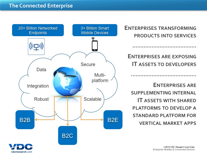
    And it really is quite interesting in terms of the transformational nature from the way that organizations are operating. It’s not just about—and we’ll talk a little bit about this in a couple of slides—it’s not just about looking at creating a more efficient and more productive workforce. It increasingly also is about how are we using mobility to engage with customers. So the whole aspect of the B to C or B to B to C channel—how are we delivering services to our employees in terms of mobile HR capabilities is also again a function of mobility that is increasingly being introduced. And within organizations, it’s also transformational from the standpoint of our ability or an organization’s ability to create and to open up value-added services that can be hooked into or connected to certainly advances in mobile and connected endpoints. So enterprises are looking to transport products into services if you will, are looking to overlay service capabilities in terms of leveraging mobile, leveraging sensor technology, leveraging location technology to deliver a much richer and a much more real-time experience. And location has a lot to do with this; location is one of the sort of the critical data points, the critical sensor points that add a lot of value and a lot of actionability to the data that is being accessed, that is being driven. So location is certainly critical, is increasingly critical, as one of the elements that organizations are looking to integrate within their mobile solutions.

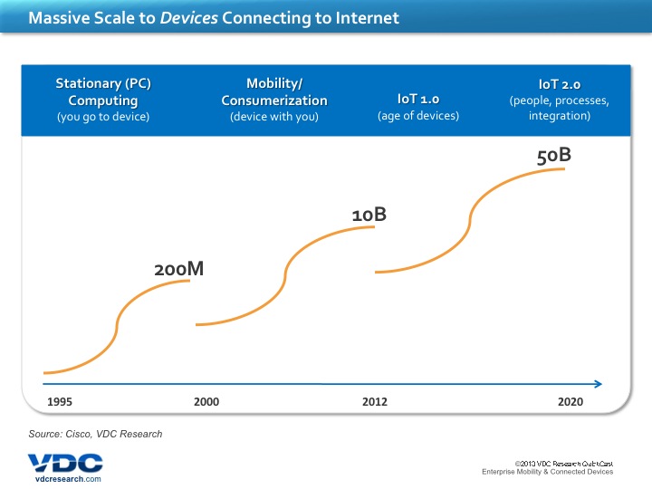
    But again, one of the trends that is important to, I guess, follow or at least play off here is the scale at which devices are connecting to the Internet, and use that as maybe a backdrop, use that maybe as a way through which to interpret and to understand sort of the massive power of mobility. And, you know, traditionally, dating back to the mid-90s, it was a very PC-centric sort of value proposition. It was a very stationary value proposition. You as the individual had to physically go to the PC, to the stationary device, to access information on the Internet, to get to the Internet-abled solution. And that scaled to about two hundred million-plus units. What we’re in the midst of right now is really the next wave, and really, I wouldn’t say the tail end, but certainly we’re well into it.

    Slide3

    Where we’re seeing mobility and certainly the whole impact and the trend of consumerization being certainly important here, whereby we’re achieving a much higher degree of personalization. And it’s really about something that you take with you and that provides access in a very mobile way, in a very distributed way, and the services that are being enabled through that. And as we evolve that, as we get to sort of the idea of, sort of the age of connective devices, where we’re getting information about remote assets that we can now manage more predictively, where we can get sort of real-time intelligence on the way that, you know, our products and our services are being consumed. And it really introduces some really valuable, you know, propositions in terms of the use of time and the impact of time, because that’s the one resource that we ultimately cannot duplicate. And how do we at best manage this very important resource? And I think that this is really fundamentally where we’re seeing a lot of this change happen.

    But going to sort of the trends with regards to mobility and sort of consumerization, there are a couple of important points to make here, especially in the context of sort of the core audience when we’re looking at enterprise mobility. So consumerization has, I guess, a lot of many different meanings, depending on who you’re talking to, but fundamentally, what’s happened over the last four or five, six years, especially with the advent of much more powerful smartphones and more recently powerful tablets, is that we’ve seen consumer technology really take a more leadership role in terms of dictating what our expectations are in terms of what a mobile device should look and feel like and how we should interact with it. And certainly we’ve seen some really really phenomenal advances in terms of ease of use, in terms of immersive user experiences, in terms of ergonomics, and quite frankly also in terms of adoption cost. With a massive scale of mobile devices that are being consumed, certainly the cost of the individual components have come down substantially. So the access to this technology, this is very powerful technology, and the barriers associated with it have lowered considerably.

    Slide4

    Now what does that mean for the enterprise worker? What are trends—or the enterprise decision maker, if you will. What do trends such as BYOD and sort of what we’ve seen now with sort of the plethora or the multitude of different operating system platforms—how do I translate that from an enterprise perspective? One of the things that we always come back to, especially in the work that we’re doing, especially for what I might consider the more mission-critical or business-critical field worker, the requirements will differ significantly from worker type to worker type. And, you know, a lot of times what’s happening with regards to consumer technology is in conflict with sort of the goals and the requirements that an enterprise mobility field solution will look to support. And some of the important things to take into consideration is certainly the environments that we’re operating in, the sensitivity if you will or the level of accuracy of location is concerned—I mean, certainly GPS technology and the integration of it in consumer technologies has advanced considerably, but there are different types of location technologies with varying levels of accuracy and obviously implications in terms of the ability to use them as enterprise tools. And then also, you know, considering things like the environmental impact in terms of the durability of the device, in terms of using the device in sort of direct sunlight, using the device that might be exposed to wet or humid conditions, can it sustain that. So we’re trying to balance those enterprise requirements with these advances in sort of ease of use and advances in sort of ergonomics and trying to sort of meet in the middle. Certainly we do expect sort of more enterprise-oriented solutions to embrace and to integrate the UI and the UX experiences that consumer devices have made so popular, but deliver it in a package that is still fundamentally addressing sort of the critical requirements amongst enterprise users.

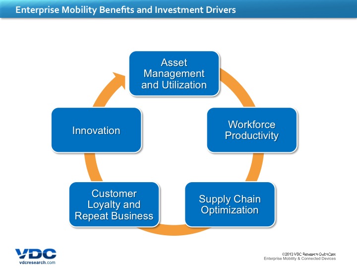
    So what is ultimately driving mobility investments? And again, as I mentioned before, the investment drivers have changed, but have traditionally really been around how can I insure that my workforce is optimizing their productivity; how can I insure that they have the critical information they need at their fingertips when they’re out in the field, in terms of service tickets that they might be managing, in terms of assets that they might be supporting. So asset management, utilization, workforce productivity, line of business, things like supply chain optimization, have all been, you know, very important sort of drivers with respect to enterprise mobility investments.

    What we have seen more recently is that we’ve certainly seen organizations, certainly forward-thinking organizations optimize against some of these drivers and some of these capabilities, and now we’re starting to see some very interesting, maybe not secondary, but additional benefits come to the fore. And it’s really now about how am I engaging with my customers to deliver better or improved levels of service, to deliver improved loyalty. How am I leveraging what I’m doing with my field workers to potentially even drive innovation in the way that we are delivering services, in its impact in, you know, product design decisions and decisions that might happen more upstream in the organization? So by connecting our entire workforce, by connecting service lifecycle management with product lifecycle management, we have a much more sort of integrated and a much more cohesive story to tell, and fundamentally a much more dynamic and competitive organization and environment.

    Slide5

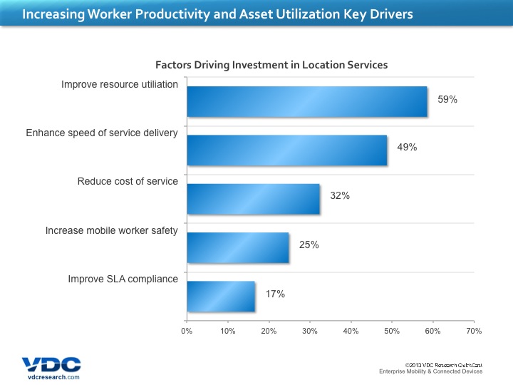
    Now, in terms of location within—and again, I understand that I’m speaking somewhat at a high level in terms of talking about field workers, and field workers can be anyone from a utility service technician to a delivery driver to someone responsible for surveying in an agricultural or mining setting, so it’s a pretty broad swath of mobile workers that we’re talking about. But in terms fundamentally of sort of consistent themes that we’re seeing across this base of mobile workers, in terms of the factors that are driving investments in location, in location services, they’re very consistent with overall mobile investment drivers and benefits. And specifically we’re talking about, again, resource utilization; we’re talking about enhancing the speed of service delivery, if it’s a service technician or a service-based workflow, as well as reducing the cost of service, especially today with high cost of fuel and high cost of manpower—we want insure that we’re maximizing it. Compliance and safety are critical requirements that are often overlooked, but especially with a lot of field workers, they are being exposed to environments that, you know, we want insure that they are as safe as they possibly can be. So using mobility and mobile solutions and location technology to increase that worker safety are some really dynamic and really interesting value propositions that we’re seeing. Disaster response—I mean, there are some really important things in terms of not only coordinating response services, but providing access to real-time data and real-time information around weather. You have a mash-up of various information that you’re looking to deliver to these early responders, these first responders, and to also second responders; it’s very important that they’re being delivered with as much location accuracy as possible. Construction and surveying—critical in this context with regards location has-been and that really is sort of fundamental within the processes that they’re supporting. But to be able to do it and deliver it through a mobile device and a mobile solution that is much more ergonomically interesting and much more intuitive is certainly what we’re seeing today.

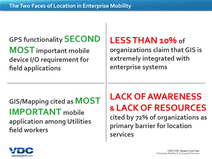
    So in looking at sort of the two faces of location within enterprise mobility—because there really is a little bit of a dichotomy here in terms of the importance and the value relative to, you know, what the actual situation is today. You know, what we’re seeing today within, or at least the research that we’ve done within, organizations with considerable field operations, that the penetration of location to track things like service vehicles is about fifty percent of organizations today, whereas fewer than a quarter are tracking resources and assets. So there’s still a relatively low, moderate, I guess, level of penetration from that perspective. However, when you look at it from the standpoint of what is important to you as a decision maker when looking at making mobile investments, GPS functionality location capabilities is the second most important I/O capability for field applications, according to our research. On top of that, you know, GIS and mapping information is cited as—in this context or in this specific scenario amongst utility workers—as the most important mobile application that they’re going to be delivering.

    So we have, you know, a scenario where we certainly are exposing and we certainly are seeing a great demand and a need for location and GPS technology. However, on the flip side—and this is really where the other face comes into it—we’re still dealing, perception’s probably the wrong word, but certainly awareness is an apt classification, where the integration of—and in this case, I’m using GIS as the example—the integration of GIS capabilities is still very limited within enterprise systems today. Ten percent or less of GIS organizations today claim that GIS is still very integrated within enterprise systems. And really the fundamental reason behind this, according to respondents, is really it’s about not only awareness, but also lack of resources. Seven in ten organizations cite that this is sort of the primary barrier for the adoption of location services within their operations. They might understand the value, but the resource issue is fundamentally there, and to a certain extent also the awareness issue is a barrier.

    So just quickly in summary, I think the points that I was hoping to make and hoping to deliver in this discussion is that as enterprise mobility continues to evolve as a discipline and as organizations continue to invest in mobile and wireless solutions for their frontline workers, for their overall business-critical and mission-critical applications, location is increasingly scaling as an important capability and one that is directly enhancing and supporting many of the field mobile solutions today. However, you know, as I said before, the articulation of the value proposition, more seamless integration of location services within existing enterprise systems—and this is an issue also for enterprise mobility in general, is that integration with backend systems—is something I would say that certainly has fallen behind. So there’s a bit of an awareness issue that needs to be addressed. And then also from a technology standpoint, from a mobile solutions standpoint, we’re certainly seeing some very interesting dynamics in terms of—and I know that Cary’s going to talk about this more in depth in a couple of minutes—but we’re seeing some very interesting dynamics whereby the demands, I guess, if you will, of consumer, or the expectations that have been introduced of consumer technologies are being interpreted into mobile solutions designed for field-based applications where you’re delivering a much more ergonomic and a lighter-weight solution with a more immersive U/I, but still addressing the unique enterprise requirements in terms of environmental conditions, in terms of providing a higher or a more sensitive GPS functionality as opposed to sort of the standard consumer functionality that is available in everyday smartphones today.

    So being able to balance that to deliver sort of an optimized enterprise design or enterprise mobile design solution is certainly something that is starting to happen. And really for developers out there, presents a very interesting opportunity, as we’re looking at the demand for the integration of location content, the integration of location intelligence, to drive even greater returns on some of their investments. And so one additional issue or opportunity, rather, as a parting thought before I hand this back over to Alan, is location for the most part today for organizations has been largely an outdoor phenomenon, if you will. And through the advent of GPS—or in other parts of the world, in Russia, GLONASS, their developments that they’ve enabled—but what we’re starting to also see now in certain industries is the opportunity for, demand for, the interest in indoor positioning systems and indoor location solutions, so that also is starting to open up some very interesting value propositions. If you think, for example, of first responders going into buildings and needing schematics and needing to understand sort of real-time locations; if you think of a healthcare facility in terms of locating assets within that facility; in terms of, you know, a warehouse and distribution center, understanding where different workers are in a particular process. So that opportunity is also very interesting and is starting to become certainly more front-and-center.

    So with that, I’d like to thank everyone again for attending and I’m going to hand this back over to Alan.

    AC: Thank you, David. We’ve taken a look through David’s eyes at the landscape before us, at the horizon, the marketplace, the developments, and now we’re going to step back a little bit upstream to the product design bench and see how industry is moving to meet the demands and anticipate the demands of users and the marketplace. Cary Kiest is a R&D engineering director with Trimble’s mobile computing solutions division. This division of Trimble has recently released an exciting new product for this market and Cary’s going to tell us about some of the challenges and considerations that go into fielding such an innovative product. Cary? Over to you.

    Cary Kiest (Trimble): Thank you, Alan, and thank you, everybody, for joining in today. I’m pleased to be here and hopefully we can have a good session. I’m going to go ahead and talk a little bit about the kind of products that we do in the business unit of Trimble I’m involved in. If you have experience with Trimble, you’ll know that for over thirty years, Trimble has been one of the pioneers early on and continue to be a leader of positioning-based solutions, many of them leveraging very heavily GPS technology. And not just GPS technology, but GPS technology integrated with other types of sensing and computing to enable a whole variety of industries that do their work primarily outdoors and in rugged environments, potentially. So things like construction, agriculture, forestry, oil and gas, things like that where you’re outdoors, equipment is expensive, investments are big, and productivity of the individual workers becomes critical and so does their safety.

    Kiest_1

    What our division does here then is we make mobile computing—in general, we call mobile computing devices, but you can think of it as sort of the handheld computers. Tablets, of course, fall into that; things that, handheld computers that are starting to look more and more like smartphones fall into that; but other form factors of handheld that have maybe a bigger keypad for users who are wearing gloves and things like that all fall into the product lines we develop here.

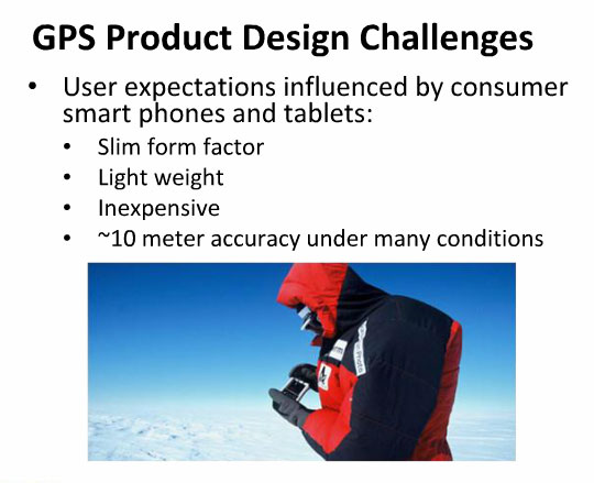
    I’m going to talk a little bit about some of the design challenges we face when we’re designing our products, and as David mentioned earlier, one of the primary things that has been driving us more recently is the user expectations that have been influenced by the rapid adoption over the last few years of consumer-based smartphones and tablets. This has been both good and bad for us. On the good—well, I should say challenging, not necessarily bad—but on the good side, because there’s been so much proliferation of, say, smartphones in particular that were position-enabled with GPS, it has opened the door to literally millions of developers who have written very creative applications and have combined positioning technology with other sorts of software, mixing with other sensing devices, coming up with creative solutions that really have flourished and provided a whole bunch of good ideas that I don’t think would have come out of just the enterprise space if it hadn’t been for just opening the door to so many people to start developing against these sorts of hardware platforms.

    So that’s been very good; it has influenced in a way where we’ve been able to leverage some of the good ideas, and also we don’t have to do as much work to train our customers because they already have quite a bit of experience now with mobile devices that they’re already comfortable using and so that makes our lives easier. Where it makes our lives a little more challenging is that users have come to expect that they can get a mobile GPS-enabled device that’s very slim, that’s very lightweight, and that’s very inexpensive.

    Kiest_2

    That’s absolutely true when you’re dealing with things like smartphones and tablets. However, the accuracy on those devices today is limited usually to around ten meters under many conditions, and what I mean by that is when you go outdoors, a whole bunch of environmental conditions are going to affect the accuracy of your GPS. For example, even whether the sky is sunny or cloudy will have an influence. Clouds are made of water, water absorbs the radio frequencies that come from the GPS satellite, and so when it’s overcast the signal levels drop. And because the GPS satellite constellation is already a very weak set of signals by the time they reach the surface of the earth, any reduction in that signal level will affect the accuracy. And so when you go out on a cloudy day, you’re going to have less accuracy; when you’re under, say, a canopy of trees, if you’re working in forestry, there’s a lot of water in those leaves and fir needles and whatnot—they will also absorb the radio frequencies. If you’re near tall buildings or other structures, on a construction site where there’s metal girders going up, or freight trains or ships or any large metal objects, those are going to reflect and send other reflective GPS signals to your device, and that’s what’s called multipath, and it ends up decreasing the accuracy of what you can read.

    And so there are a whole variety of outdoor conditions that are going to start reducing the accuracy that you might otherwise get when you’re in open sky. And it’s when you get into those sorts of environments, which are very common for outdoor mobile workers, that’s where the expectation that you can get the accuracy on a really slim device is most challenging. And so we have been influenced by that, absolutely, and are designing against that.

    There are some things that we can do, though. We want to try and improve our GPS accuracy and keep things slim as much as we can, but the things that most influence the ability to do that is your antenna, and primarily it’s the size of the antenna. To keep a device slim is definitely a motivation, but there is no way around the physics that having a larger antenna that can receive more signals from the satellites is your best strategy for improving GPS reception. Another major factor is the orientation of the antenna. Most antennas that receive GPS signals, the ones that work the best have sort of a flat shape to them, and the flat side of that, to get your best signal reception, needs to be pointing generally straight up.

    Now if you can imagine having a smartphone or a tablet that’s a very thin device, usually the flattest surface of that device is pointed at your face so you can see it, and unless you’re looking straight down or straight up at the device, it’s not going to have that flat surface pointing up to where the satellite constellation is positioned. And so that ends up becoming a challenge, too. What you’ve probably seen if you’ve used industrial GPS devices in the past are, you know, larger antennas that are disk-shaped that you want to mount in a way that the disk is pointing straight up. And that’s for a very good reason, and it is so you can see as many satellites as possible with the most signal that you can get from those.

    Kiest_3

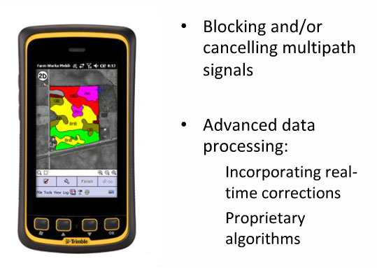
    The next thing you want to try and do is block or cancel the multipath signals that I talked about earlier. Specifically, multipath, again, are the signals that don’t come directly from the satellites, but that are reflecting off of other objects in your surrounding area, be it the sides of buildings or metal structures, or even the ground in some cases, which can come back up and interfere with the native GPS signals that are coming straight at you. And so you can block those by adding shields or ground plains—usually directly below your GPS antenna is where you want to do that.

    However, again, if you can imagine the example I mentioned earlier, where the GPS antenna wants to be sort of a flat structure pointing up, you’re going to want that shield to be oriented about the same way as the GPS antenna—flat and pointing up—and in fact you want that shield to be even a little larger than the antenna. So there’s another challenge that we face when trying to give a better antenna solution against the expectations of consumer electronics.

    One of the last areas is advanced data processing. Aside from getting, you know, optimal signals and blocking multipath and things like that, there’s quite a bit of work you can do once you do get the signals from the GPS satellites in to try and really selectively choose the best signals and filter out or ignore what you think might be multipath, what you think might be noise, and that research is going on continually, and quite a bit of that has actually worked its way into consumer devices, so that they can improve their accuracy with very small antennas, with very lightweight components. So that’s always an area that we’re working on as well. An additional challenge with that, however, though, is the amount of battery power you consume, especially when you’re in a mobile device. You only have so much charge in your battery and you’re trying to make that last as long as possible, you need to be careful how much computing power you spend on what seems like a background task of just receiving GPS signals and recording their position. If you spend too much power doing a lot of number crunching on that, you’ll drain your battery faster.

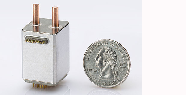
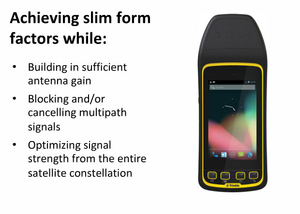
    And so what we’ve tried to do is somehow take those challenges that the consumer expectations have put on our market, and design solutions that optimally put us in a good solution to balance the two halves of this: the challenges versus the expectations. And the product that we’ve just announced now is, or actually yesterday it just came out, is an improved GPS accuracy version of our Juno T41 product. The picture you see on the slide right now is a user holding that, and if you look, what you’ll see is a device that looks like a smartphone, but it has sort of an extended black cap or snout coming out the top of it. And what you see there is, that black snout is where the GPS antenna and ground plain are installed. It doesn’t really show up in the photos so well, but that snout is at a slight bit of an angle tipped forward, and the idea there is that we’ve studied the angle at which users are most likely to hold the device, okay, and figured out, well, it’s probably not going to point straight up at the sky, so can we find a nice compromise where we can point the antennas straight up towards the satellites that doesn’t make the device too awkward?

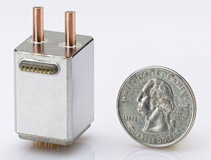
    So again, it’s a balancing act between keeping the device slim, keeping it light, but also positioning the antenna such that it has a good view of the satellites overhead. So that’s the form factor we’ve come up with, and that’s one solution you can do. This next slide that you’ll be seeing here in a second is another view of the same device, and so one of the things that we’ve done, of course, is just put in a larger antenna and position it correctly, and so what that does is that gives us that antenna gain, that gives us the ability to pull in more satellites and have stronger signals from each of those satellites. Having stronger signals allows us then to effectively gain accuracy in the more challenging conditions—not just an open sky on a sunny day, but under clouds, under tree cover, in multipath environments, you know, in an urban area where there’s big equipment, things like that. That’s where you really start to see the accuracy difference pay off when you go to a more advanced GPS system like this. You often see, for example, in a consumer device that can get you within seven, eight, nine meters of position accuracy pretty repeatably out in an open area under sunny sky, you walk near a building and that will immediately jump out to like twenty or thirty meters.

    For mobile workers, that’s almost no information at all, if you’re trying to, for example, figure out which power meter you’re looking at, or if you’re trying to understand which other physical asset you’re close to when there might be several of those assets in an array along the side of the building. So those are the sorts of applications where that accuracy really starts to help. And we’re adding the antenna gain, blocking or cancelling the multipath with shielding, and then optimizing the signal strength from the entire satellite constellation becomes an issue. I should also mention that when you do get up close to a building, you’re not going to see the GPS satellites through that building most likely, and so the satellites that are viewable overhead, the number of them gets cut roughly in half, and so it becomes very important to have as much signal as you can still get from the satellites that are still in view. You will have some degradation of your position accuracy when you get up close to a building; the goal with a product like what we’ve done is to try and minimize that degradation and still give you as much position accuracy as we can under those situations.

    One of the next challenges is, of course, maintaining light weight, and because users have become used to putting the device in their pocket or if they’re carrying it around all day, just the weight of the device will cause fatigue after a while. That becomes a challenge for us when we have to put larger antennas and ground plains in. It’s also a challenge for us when we have to put enough battery power in to have the device last all day. One of the design challenges for making mobile computers is you’re putting it in the hands of someone who could very well be putting in a full eight- or ten- or even twelve-hour shift, where they’re not just looking at the device once every, you know, few minutes to see if they’ve gotten a new text message—they’re using it the whole time, which means that the cellular radial may be sending data back and forth all the time, they’ve got the display backlight on all the time, they may be connected to another device via Bluetooth all the time, they may be using GPS all the time. And so the usage is usually a lot more demanding than a consumer device. And really the only strategies you have to hedge against that are to put in more battery power and then spend a lot more time in your software development to be as efficient with that power as you can—only keeping things on when you absolutely need them and turning them off when you don’t.

    And then the other thing that’s going to add to weight is just ruggedizing the device. We build our devices to not just function outdoors and have good GPS accuracy, but also to be rugged, so if I drop it, for example, I can’t have it break. I’m out there—usually the data I’m collecting is worth more than the device itself, and so I’ve got to protect that data, I’ve got to be able to continue my day on the job site. If I’ve driven several miles and I’m four hours into my job and I drop the device or something happens to it, it drops into a puddle of water, I can’t have that end my work day. I’ve got to be able to pick the thing up and dry it off, dust it off, and continue working. Or I’ve just cost my company certainly the wages that I would’ve expected to earn that day, but also it may be that that data is necessary on that day because you have large equipment scheduled to come in the following day that you had to schedule days in advance and it’s costing thousands of dollars. So the economics of it all become very important, and so having these devices be rugged and reliable is a big motivating factor for us. The way to do that most often is to add mass to it: you put more bumpers on it, you have stiffer frames, you have more plastic, all of that adds weight so the device ends up being heavier. And then the heavier the device is, the stronger you have to make it, and you sort of get into a spiral there, where to make it stronger you add more weight, but you’ve added more weight so it has to be stronger, and so make it stronger you have to add a little more weight, and then so on and so forth, until finally you have a device that’s rugged enough to meet the challenges that it’s going to face. So we spend a lot of time trying to do all of these things: put the right antennas in, put the right ground plains in, work on the power consumption, have enough battery in there, and make the device rugged. These are all major portions of what goes on in our minds when we design these products.

    Okay, the next challenge has been to try and make the device inexpensive, and part of the issue we have there is that we are using higher performance components than they usually put in consumer-grade devices. Those components cost more because they’re higher performance. Another challenge we have is we don’t typically have the buying leverage that, say, one of the large smartphone manufacturers are going to have. If they’re planning to build several million devices in six months, they’re going to have a lot more buying power to get their components than people who are in a more niche environment like ourselves who are looking at buying, say, tens of thousands. So we don’t have the buying power; we’re going to have to end up paying more for our components that way.

    The other thing that we have is we usually sell our products direct to an end user who, or integrator, value-added reseller, who are going to bundle it with software and other services that then go to the, out to the field. And once they go out to the field, it’s the user’s choice as to which carrier they want to add to it, so they’ll buy a separate data plan. When you go buy a smartphone, you may very easily think, well, this thing only cost ninety-nine or a hundred dollars—well, that’s not really true. It actually cost several hundred dollars, but they’ve buried a lot of that cost into a service plan that’s going to last, say, two years. So we don’t have the ability to hide our costs in service plans like that. And that just influences user expectations about what a device like this should cost. So, you know, like all businesses, we have pressures to keep the costs low, and these are some of the ones that we struggle with the most to try and overcome.

    So, having said all that, what does a company like us, or a group like ours, have to do to put all this together and get it right? Well, first of all, you have to have a very deep knowledge of GPS systems and their use cases. There’s a lot more to GPS technology than just receiving the satellites, crunching the numbers, and reporting a position. There’s all sorts of augmentations and correction services that can be added to help improve your accuracy in situations where you may not have a clear view of the sky or good signals. You have to know the use cases really very well, and I talked a little bit about this before when I mentioned the differences between, say, using your device in an open sky environment or near large objects that are going to cause multipath or under tree cover or all of the above—how important is that?

    Well, knowing your customer, knowing the workflows, knowing the kinds of situations they’re going to be in—are they going to be standing still, are they going to be on the move, how long do they want to spend at any one point if they’re moving around—all of those sorts of things and being very good at understanding what’s going on with your customers is something you have to have. So we’ve made that our business for many many years now, and we have all that. Extensive design modeling and testing: it’s not easy to design these devices. You can get away with just buying an antenna, buying a GPS module, putting it in something, turning it on, and seeing how it works, but you’re not going to wring all of the performance out of it and avoid all the problems unless you have pretty sophisticated tools to do all this. So you have to make an investment, and of course we’ve done that; again, you know, Trimble has been pioneering GPS for over thirty years now, so we have a lot of real powerful design assets throughout the corporation that we tap into. You have to select and integrate the right components. This is really important: you have to know where the problems are and where some of the component providers may have a weak spot in their product line-up, and they’re not going to advertise those.

    So through experience and through a lot of testing and proof of principle work, you’ll learn that over time. And so we do spend a lot of our research budgets doing all that, working with the suppliers of the components we use to get the best out of what they have available. And then the next one is optimally balancing all the trade-offs presented earlier. I’ve tried to paint a picture here to describe a lot of the challenges, and there are many, and at the end of the day what you end up doing is deciding how to make compromises, like all real good engineering problems. Do I spend more and get maybe a few more inches accuracy, or do I spend a little less—you know, where do we set the knobs on that? And so there, again, understanding how the systems work and what your customers really need and then choosing where to settle those knobs and balance the trade-offs is an important part of getting the right product out there.

    That’s really going to help people and hit the market in an area it wants. And then staying on the leading edge of GPS technology improvements. You know, we’re not done. There are neat new things coming out, on the horizon, on our roadmaps, that we need to be aware of or we stand the terrible chance of falling behind in a game that we were one of the early leaders in and remain a leading player even today. And so keeping our eyes out on what other people are doing, pressing forward with our own research in these areas, and being innovative is a key part to staying in this business and providing value.

    And with that, I think I’m done with my presentation, so I will hand it back to Alan now. And I’ll want to thank you all again for your time and listening in today.

    AC: Thanks very much, Cary. We have a few minutes left and we have some questions from the audience. I’m going to jump right into the first one. One of our listeners wants to know—and I’ve modified his question a little bit: going further into the future than what you have talked about so far, what advances in mobile location technology can we anticipate a) in the current financial year, b) in the next two or three years? I think this listener is trying to gauge the market, gauge the advent, the rate of advent of technology, and determine the sweet spot for a purchase. Do it now, or wait for a little bit more capability and do it later? And of course when you’re talking about an enterprise equipping a whole crew or a vast number of workers, that can be a significant investment and an important question to know when to time your purchase. I’d like to open that to either of you gentlemen: what advances beyond what’s currently envisioned, both in technology and applications, can we expect in the next year, and then in the next two to three years?

    CK: I can go ahead and take this one—this is Cary Kiest again. Speaking from my own perspective here at Trimble and then also from the perspective of keeping an eye on what we see, what I think you’re going to see in the near term here are slight improvements to products that are already out there and a little bit more product differentiation. For example, the product I talked about earlier that we just announced sort of splits the difference between the very accurate GPS devices that get down into the centimeter range and the ones that are more into, like, the five- to ten-meter range. We’ve got one that’s in the one- to two-meter range, and so that’s really more of a packaging thing where we’re trying to give something that is in sort of a middle ground between two areas that previously existed. You will see from us later this year something similar in a tablet space. And so that’s an area where it’s either market differentiation or a slight improvement to what’s already out there.

    As we look a little further down the road, what you’ll see is improvements in cost and the performance you get for the cost. You’ll also, I think, see—and this is something David talked about a little bit earlier—there’s a lot of interest industry-wide in indoor positioning, and specifically what that refers to is how do I know where I’m at when I don’t really have good access to GPS signals? And so there’s a lot of research and some early products coming out that will allow you to know where you are as you transition from outdoors where you have GPS to indoors—and it may not just be indoors, it may be on a construction site where now, you know, you’ve started to put up enough steel girders and whatnot and the building is taking shape. How can I know where I’m at on that site where I don’t have good GPS signals, and how can I improve the accuracy? Can I know where I’m at down to within, say, a meter, or even a couple feet or a few inches? So you’re going to see things like that come out; I think you’re also going to see mobile computing be defined into the wearable space also. For enterprise things, you know, you’ve probably been hearing a lot of buzz about Apple’s iWatch that they’re talking about—you’ll see this sort of thing come out in the enterprise space too, but that’s further down the road. It might be a simple thing that workers wear that knows their position and maybe monitors a few conditions as they go into a hazardous location or they’re on a job site where it’s important to know where everyone’s at. And so I think those are sort of the main areas of investment you’ll see come out from our industry over the next three to five years.

    AC: David, anything to add to that?

    DK: Yeah, I mean, I would certainly concur with what Cary said. I think what we’re in right now over the next couple years is a period of refinement. I don’t think certainly in the near term even you’re going to necessarily see technologies coming out that are, you know, significantly different in terms of their capabilities, but we’re going to see a refinement in terms of a better alignment with solutions with particular applications. So fundamentally from the end user, from the individual with this question, it really comes back down to what are they looking to do? What’s the application they’re looking to support? And that will ultimately determine sort of the viability of today’s technology. There isn’t anything—I mean, what we see with a lot of customers, especially because of the fast-paced nature of mobility and the seemingly endless change, is timing the perfect entry point. And one thing that we won’t stop in this industry is innovation and change. So in terms of waiting for that perfect solution, so to speak, I mean, you can spend a lot of time waiting for that because there’s always going to be refinement and improvement to it. So I think a lot of times what we recommend our customers is, yeah, you might not want to take the big bite right now—we understand that, we want prudent investments—but a lot of times when asked what they would do differently, when we ask a lot of investors, is we would have started sooner.

    So I think in terms of the maturity, the accessibility, the availability of technologies that can address most applications, you know, that’s on the market today. So I say—again, not knowing the application, there’s no real reason quote-unquote to wait. But certainly advances around indoor positioning systems, I mean, that’s really where we’re seeing probably, over the next two to three years, probably the greatest change happening. Certainly advances in mobile form factors, and quite frankly, yes, cost of technology, cost of services will come down. And I think also the integration of, you know, some of this content from an application development design perspective will become a little bit more seamless.

    AC: All right, thanks. We’re at the hour straight up, but I’m going to squeeze a last few couple of minutes of value out of this webinar for our listeners by asking one more question, and we’ll treat this fairly quickly if we can. There’s a lot that can be said about it, for sure, and our July article did treat this subject somewhat. One of our listeners wants to know, in your opinion, what is the best development platform for application development? Do you think one should model the app and then write separate code streams for Windows, Android, iOS, and so on, or—the question always boils down to who is going to win the platform battle? And is there room for more than one? Either of you gentlemen care to comment on that?

    CK: I can go ahead and start on that one again. This is Cary Kiest. We—here at our group, most of our customers are writing something a little more advanced than, say, a user app that you might download from the Play Store or something like that. And so we have run into from time to time users who try to use a cross-platform development tool to port their app that they’ve written, say, for iOS over to Android or Windows Imbedded, and they usually run into a problem when they get down a couple layers closer to the hardware. And specifically, when you get into devices like ours or computers like ours where we’ve used more advanced, say, GPS systems that have more parameters and more capabilities, you have to really understand how to integrate with those and tap into those capabilities in a way that a cross-platform development system isn’t probably set up to handle. So we usually recommend people to not try and do that for applications that run on our devices that are very user-specific and pointed at the enterprise. To get the kind of performance you need with the technology out there today, we definitely recommend going and developing in the environment that’s suited for that particular operating system.

    DK: Yeah, I mean, I won’t add much to that, Alan, except there—you know, this is one of these sort of the conflicts of, you know, the consumerization as we’re seeing this multitude of platforms. And certainly when you’re looking at the base numbers, you know, iOS and Android are outpacing any other platform by leaps and bounds. But that tells only part of the story, if you will. We’re certainly seeing the potential for, you know, OS change also on sort of these more enterprise-specific devices and I think there is room for alternative platforms. But fundamentally, getting down to the question, is what’s the appropriate development approach today for these, what I would consider more business-critical, mission-critical, field applications—today still, I would say that for a number of reasons, native development will still trump cross-platform development, even though we’re seeing some interesting advances, and certainly the HTML-5 spec and its ability to address, you know, offline capability and sort of dynamic caching and thinking capabilities or incremental thinking capabilities. So I think the improvements are occurring, but in terms of user experience, in terms of offline support, and to Cary’s point, in terms of true access of device–site capabilities, for these types of applications today, native development is, I would still say, sort of the best approach.

    AC: Thank you, and with that we’ll wind up the content section of our program. Thanks to both you gentlemen, Cary and David, for your insights; thanks to the audience for joining us—the content must have been compelling because I estimate about ninety, above ninety percent of you stayed tuned in for the entire webinar, including running five minutes over. Thanks for your indulgence. Thanks also to our sponsor, Hemisphere GPS.

  • Northrop Grumman Demonstrates Micro-Gyro Prototype for DARPA Program

    Northrop Grumman Demonstrates Micro-Gyro Prototype for DARPA Program

    Photo: Northrop Grumman Corporation
    Photo: Northrop Grumman Corporation

    Northrop Grumman Corporation has developed and demonstrated a new micro-Nuclear Magnetic Resonance Gyro (micro-NMRG) prototype for the Defense Advanced Research Projects Agency (DARPA), providing precision navigation for size- and power-constrained applications.

    The development of a hermetically sealed micro-NMRG that meets precision navigation requirements along with a successful prototype demonstration marks the fourth and final phase of DARPA’s Navigation-Grade Integrated Micro Gyroscopes (NGIMG) program. The culmination of the eight-year program is a micro-NMRG that offers near navigation-grade performance for the next generation of high-precision inertial sensors.

    Northrop Grumman’s micro-NMRG technology uses the spin of atomic nuclei to detect and measure rotation, providing comparable performance to a navigation-grade fiber-optic gyro in a small, lightweight, low-power package. Additionally, the gyro has no moving parts and is not inherently sensitive to vibration and acceleration. The technology can be used in any application requiring small size and low power precision navigation, including personal and unmanned vehicle navigation in GPS-denied or GPS-challenged locations.

    “Our miniature gyro technology offers unprecedented size, weight and power savings in a compact package, exceeding program requirements,” said Charles Volk, vice president of Northrop Grumman’s Advanced Navigation Systems business unit. “This important technology can help protect our warfighters by offering highly accurate positioning information, regardless of GPS availability.”

    The NGIMG effort is part of DARPA’s Micro-Technology for Positioning, Navigation and Timing program that aims to develop technology for self-contained, chip-scale inertial navigation and precision guidance. Northrop Grumman began the first phase of the NGIMG effort in October 2005 and has consistently met or exceeded the performance goals of each program phase.

  • GPS IIF-5 Launch Delayed

    The scheduled October 23 launch of GPS IIF-5, the fifth in the current “follow-on” generation of GPS satellites, has been postponed in order to complete a review of an adjustment made to the rocket’s upper stage engine. A fuel leak in that engine of the Delta 4 rocket during a GPS launch in October of last year created some worries for the Air Force and the United Launch Alliance (ULA), although the satellite successfully reached its intended orbit despite the upper stage producing less thrust than expected.

    A subsequent  investigation determined a fuel leak in the engine system was responsible. Two  medium Delta IV rockets and one heavy version have launched since then, but ULA said continued investigation had produced new information about the engine’s first start.

    While no new definitive launch date has been set, the ULA released a statement:

    “The ongoing Phase II investigation has included extremely detailed characterization and reconstructions of the instrumentation signatures obtained from the October 2012 launch and these have recently resulted in some updated conclusions related to dynamic responses that occurred on the engine system during the first engine start event.

    “The GPS IIF-5 Delta IV launch is being delayed to allow the technical team time to further assess these updated conclusions and assess the improvements already implemented and determine whether additional changes are required prior to the next Delta IV launch.

    “The Delta IV booster for the GPS IIF-5 mission has completed the standard processing and checkout on the launch pad and will be maintained in a ready state for spacecraft mate and launch pending completion of this assessment. A new launch date will be established when the assessment of the updated dynamic response information is completed in the coming weeks.”

    .