Author: GPS World Staff

  • Signal Quality of Galileo, BeiDou

    Signal Quality of Galileo, BeiDou

    By Steffen Thoelert, Johann Furthner, and Michael Meurer

    Future positioning and navigation applications of modernizing and newly established GNSSs will require a higher degree of signal accuracy and precision. Thus, rigorous and detailed analysis of the signal quality of recently launched satellites, including the discovery of any possible imperfections in their performance, will have important implications for future users.

    Global navigation satellite systems achieved amazing progress in 2012, with major milestones reached by the various navigation and augmentation systems, bringing new satellites and satellite generations into orbit. Since the complexity of the satellites and also the requirements for a precise and robust navigation increase consistently, all of the newly available signals of the existing or emerging navigation satellite systems must be analyzed in detail to characterize their performance and imperfections, as well as to predict possible consequences for user receivers.

    Since the signals are well below the noise floor, we use a specifically developed GNSS monitoring facility to characterize the signals. The core element of this monitoring facility is a 30-meter high-gain antenna at the German Aerospace Center (DLR) in Weilheim that raises GNSS signals well above the noise floor, permitting detailed analysis. In the course of this analysis, we found differences in the signal quality in the various generations of the Chinese navigation satellite system BeiDou, differences which influence the navigation performance.

    This article gives an overview of new navigation satellites in orbit. For selected satellites, a first signal analysis reveals important characteristics of these signals. The data acquisition of these space vehicles was performed shortly after the start of their signal transmission to get a first hint about the quality and behavior of the satellites.

    For more detailed analysis, these measurements should be repeated after the satellites become operational. Then the acquired high-gain antenna raw data in combination with a precise calibration could be used for a wider range of analyses: signal power, spectra, constellation diagrams, sample analysis, correlation functions, and codes to detect anomalies and assess the signal quality and consequently the impact at the user performance.

    Measurement Facility

    In the early 1970s, DLR built a 30-meter dish (Figure 1) for the HELIOS-A/B satellite mission at the DLR site Weilheim. These satellite missions were the first U.S./German interplanetary project. The two German-built space probes, HELIOS 1 (December 1974–March 1986) and HELIOS 2 (January 1976–January 1981), approached the Sun closer than the planet Mercury and closer than any space probe ever. Later, the antenna supported space missions Giotto, AMPTE, Equator-S, and other scientific experiments.

    Figure 1. 30-meter high-gain antenna.
    Figure 1. 30-meter high-gain antenna.

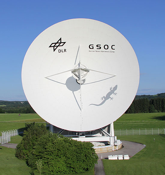
    In 2005, the Institute of Communications and Navigation of the DLR established an independent monitoring station for analysis of GNSS signals. The 30-meter antenna was adapted with a newly developed broadband circular polarized feed. During preparation for the GIOVE-B in-orbit validation campaign in 2008, a new receiving chain including a new calibration system was installed at the antenna. Based on successful campaigns and new satellite of modernizing GPS and GLONASS, and GNSSs under construction — Galileo and COMPASS — the facility was renewed and updated again in 2011/2012.

    This renewal included not only an upgrade of the measurement system itself, but also refurbishment of parts of the high-gain antenna were refurbished.

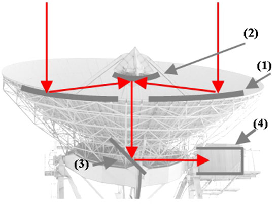
    The antenna is a shaped Cassegrain system with an elevation over azimuth mount. The antenna has a parabolic reflector of 30 meters in diameter and a hyperbolic sub-reflector with a diameter of 4 meters. A significant benefit of this antenna is the direct access to the feed, which is located within an adjacent cabin (Figure 2). The L-band gain of this high-gain antenna is around 50 dB, the beam width is less than 0.5°. The position accuracy in azimuth and elevation direction is 0.001°. The maximum rotational speed of the whole antenna is 1.5°/second in azimuth and 1.0°/second in elevation direction.

    Figure 2. The shaped Cassegrain system: (1) parabolic reflector of 30 m diameter; (2) hyperbolic sub- reflector with a diameter of 4 meter; (3) sub-reflector; (4) Cabin with feeder and measurement equipment.
    Figure 2. The shaped Cassegrain system: (1) parabolic reflector of 30 m diameter; (2) hyperbolic sub- reflector with a diameter of 4 meter; (3) sub-reflector; (4) Cabin with feeder and measurement equipment.

    Measurement Set-up

    The antenna offers another significant advantage in the possibility to have very short electrical and high-frequency connection between the L-band feeder and the measurement equipment. As mentioned earlier, the challenge for future GNSS applications is the high accuracy of the navigation solution. Therefore, it is necessary to measure and then analyze the signals very accurately and precisely. To achieve an uncertainty of less than 1 dB for the measurement results required a complete redesign of the setup, which consists of two main parts:

    • paths for signal receiving and acquiring the measurement data;
    • calibration elements for different calibration issues.

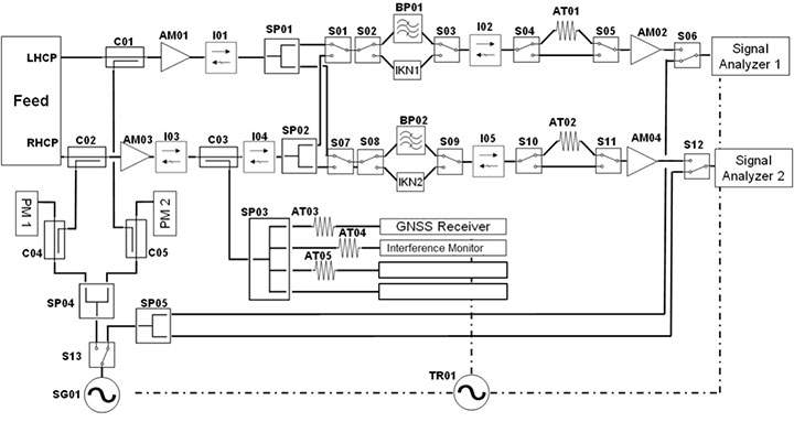
    The path for receiving the signal and acquiring the measurement data consists of two signal chains, each equipped with two low-noise amplifiers (LNAs) with a total gain of around 70 dB, a set of filters for the individual GNSS navigation frequency bands, and isolators to suppress reflections in the measurement system. With this setup it is possible to measure right-hand circular polarized (RHCP) and left-hand circular polarized (LHCP) signals in parallel.

    This provides the capability to perform axial ratio analysis of the satellite signal, and consequently an assessment of the antenna of the satellite. Using the switches SP01 and SP02, the measurement system is also able to acquire data from two different bands at the same time. This enabless investigations concerning the coherence between the signals in post-processing.

    The signals are measured and recorded using two real-time vector signal analyzers with up to 120 MHz signal bandwidth. Both analyzers are connected to a computer capable of post-processing and storing the data. Additional equipment like digitizers or receivers can be connected to the system using the splitter III outputs, where the unfiltered RHCP signals are coupled out after the first LNA. A high-performance rubidium clock is used as reference signal for the whole measurement equipment. In front of the first LNA of each chain, a signal can be coupled in for calibration issues.

    Control Software. Due to the distance of the antenna location from the Institute at Oberpfaffenhofen (around 40 kilometers) it was necessary to perform all measurement and calibration procedures during a measurement campaign via remote control. A software tool was developed which can control any component of the setup remotely. In addition, this software can perform a complete autonomous operation of the whole system by a free pre-definable sequence over any period of time. This includes, for example, the selection of the different band-pass filters, the polarization output of the feed, and the control of the calibration routines.

    After the measurement sequence, the system automatically copies all data via LAN onto the processing facility, starts basic analysis based on spectral data, and generates a report. Sophisticated analysis based on IQ raw data is performed manually at this time.

    Absolute Calibration

    To fulfill the challenge of highly accurate measurements, it is necessary to completely characterize all elements of the measurement system, which comprises the antenna itself and the measurement system within the cabin after the feed. An absolutely necessary precondition of the calibration of the high-gain antenna is a very accurate pointing capability. The pointing error should be less than 0.01° concerning antennas of this diameter.

    Furthermore, it is important to check long-term stability of these characterizations and the influences of different interference types and other possible error sources. This has to be taken in to account, when it comes to a point where the value of the absolute calibration has the same range as the summed measurement uncertainties of the equipment in use.

    Antenna Calibration. High-accuracy measurements require not only the correct antenna alignment but also accurate power calibration of the antenna. To determine the antenna gain, well known reference sources are needed. These could be natural sources like radio stars or artificial sources like geostationary satellites.

    Standard reference signal sources for the calibration of high-gain antennas are the radio sources Cassiopeia A, Cygnus, and Taurus. All these radio sources are circumpolar relative to our ground station, and therefore usable for calibrations at all times of the year. A further advantage of these calibration sources is the wide frequency range of the emitted signals. Thus, contrary to other signal sources (like ARTEMIS satellite L band pilot signal) the antenna gain can be calibrated in a wide bandwidth. With the help of the well-known flux density of the celestial radio sources and using the Y-method, the relation between the gain of the antenna and the noise temperature of the receiving system, or G/T, can be measured. Measuring the noise figure of the receiving system, the antenna gain can finally be calculated.

    System Calibration. The measurement system calibration behind the feed is performed using wideband chirp signals. The chirp is injected into the signal chains via coupler I and II (Figure 3). The calibration signal is captured by the two vector signal analyzers. In the next step, the signal is linked via the switches directly to the analyzers, and the chirp signals are recorded as reference again. It has to be taken into account that more elements are in the loop during the chirp recordings compared to the receiving chain. These are the link between the signal generator and the couplers and the direct path to the analyzers.

    Figure 3. Measurement setup overview.
    Figure 3. Measurement setup overview.

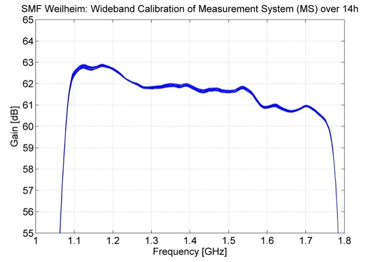
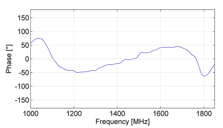
    To separate the receiving chain from the additional elements within the wideband calibration loop, two more measurements are needed. The injection path from the signal generator to the couplers and the direct paths are characterized by network analyzer (NWA) measurements. Based on the chirp and NWA measurements, the transfer function of the system is calculated to derive the gain and phase information. To determine the calibration curve over the frequency range from 1.0 GHz to 1.8 GHz, a set of overlaying chirps with different center frequencies is injected into the signal paths and combined within the analysis. Figure 4 and Figure 5 show the results of the wideband calibration of gain and phase.

    Figure 4. Gain of the measurement system after the feed over 14 hours.
    Figure 4. Gain of the measurement system after the feed over 14 hours.
    Figure 5. Phase of measurement system.
    Figure 5. Phase of measurement system.

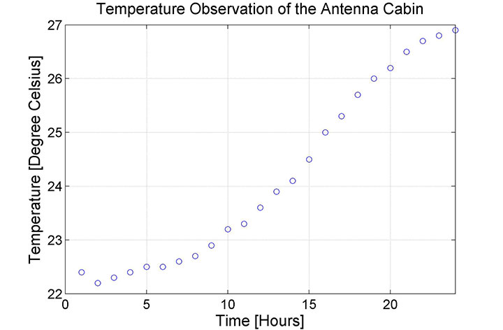
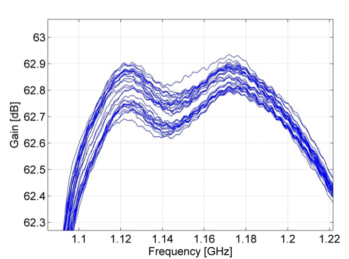
    Is it enough to determine the gain only once? If we assume that there is no aging effect of the elements, and the ambient conditions like temperature are constant, the gain should not change. In reality the behavior of the system is not constant. Figure 6 shows the temperature within the cabin during a failure of its air conditioning system. Figure 7 shows the corresponding gain of the measurement system during the temperature change in the cabin of about 5° Celsius. Clearly, it can be seen that the gain changed around 0.2 dB.

    Figure 6. Cabin temperature increase during outage of the air condition concerning measurements shown in Figure 7.
    Figure 6. Cabin temperature increase during outage of the air condition concerning measurements shown in Figure 7.
    Figure 7. Gain variations of the measurement system based on temperature variations in the cabin (see Figure 6).
    Figure 7. Gain variations of the measurement system based on temperature variations in the cabin (see Figure 6).

    This example shows the sensitivity of the system to changes in environmental conditions. Usually the measurement system is temperature-stabilized and controlled, and the system will not change during data acquisition. But every control system can be broken, or an element changes its behavior. For this reason, the calibration is performed at least at the beginning and at the end of a satellite path (maximum 8 hours).

    Measurement Results

    Here we present selected results from the European Galileo and the Chinese BeiDou navigation systems.

    Galileo FM3 and FM4. In October 2012, the third and fourth operational Galileo satellites, FM3 and FM4, were launched into orbit. Signal transmissions started in November and in December, respectively. Both satellites provide fully operational signals on all three frequency bands, E1, E5, and E6. The measurement data of both satellites were captured in December 2012, shortly after the beginning of the signal transmission. Figure 8 shows the spectra of both satellites for El, E5, and E6 bands. The quality of the transmitted signals seems to be good, but for the El signal of FM4 satellite, minor deformations of the spectra are visible.

    Figure 8. Measurement results of Galileo IOV FM3 & FM4: El, E5 and E6 spectra.
    Figure 8. Measurement results of Galileo IOV FM3 & FM4: El, E5 and E6 spectra.

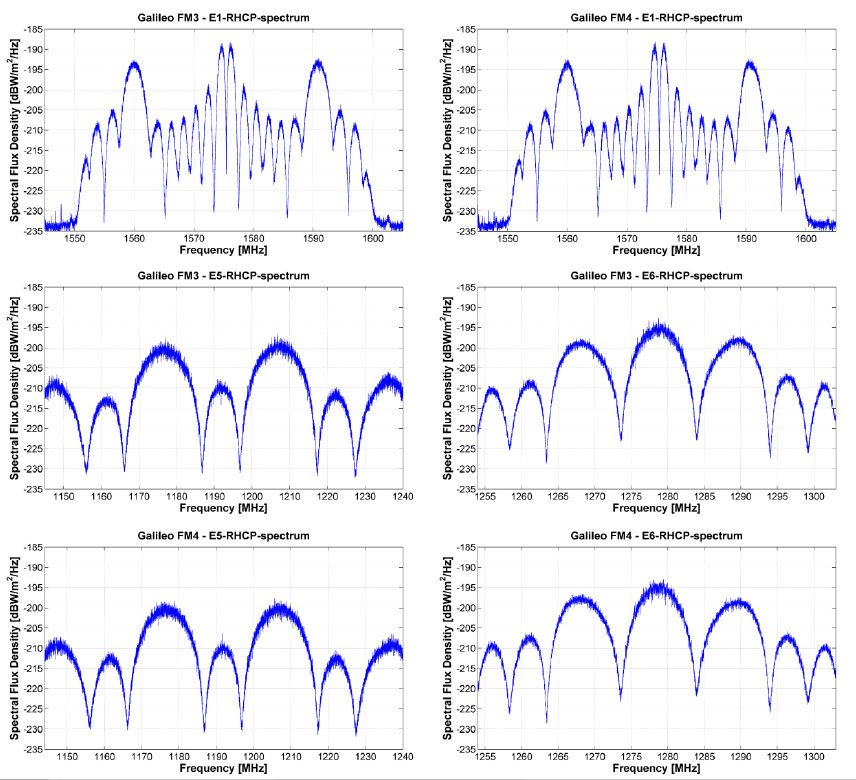
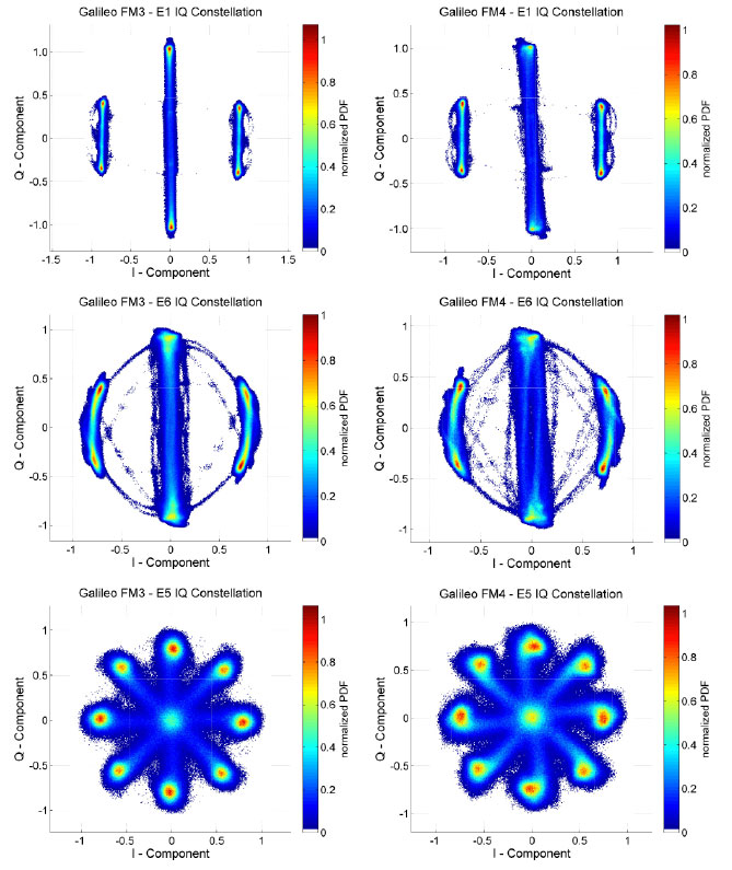
    Figure 9 shows the results of the IQ constellations both for FM3 and FM4 concerning each transmitted signal band. The constellations and consequently the modulation quality of each signal are nearly perfect for the FM3 satellite. The IQ constellation diagrams of FM4 show minor deformations in each band. What impact these imperfections create for future users has yet to be analyzed. Both satellites were at the time of measurement campaign still in the in-orbit test phase and did not transmit the final CBOC signal in the E1 band. It could be expected that especially the signals of the FM4 will be adjusted to become more perfect.

    Figure 9  Measurement results of Galileo IOV FM3 & FM4: E1, E5, and E6 - IQ Constellation.
    Figure 9 Measurement results of Galileo IOV FM3 & FM4: E1, E5, and E6 – IQ Constellation.

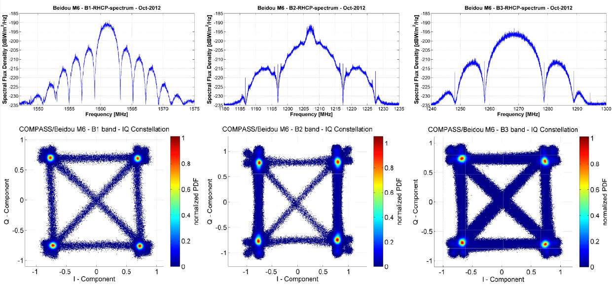
    BeiDou M6. BeiDou satellites transmit navigation signals in three different frequency bands, all are located adjacent to or even inside currently employed GPS or Galileo frequency bands. The center frequencies are for the B1 band 1561.1 MHz, B3 band 1268.52 MHz, and B2 band 1207.14 MHz.

    In 2012, China launched six satellites: two inclined geostationary space vehicles and four medium-Earth orbit ones, concluding in September (M5 and M6) and October 2012 (IGSO6). There have been further BeiDou launches in 2013, but these satellites’ signals are not analyzed here.

    Figure 10 displays calibrated measurement results from the Beidou M6 satellite. The spectra of the B2 and B3 band of the Beidou M6 satellite are clean and show no major deformation. Within the B1 spectra, some spurious results, especially on top of the side lobes, are obvious. This behavior has to be investigated more in detail to determine their origin. The IQ diagrams, which visualize the modulation quality, show also no major deformation. Only within the B3 signal, a marginal compression of the constellation points can be seen, which points to a large-signal operation at the beginning of the saturation of the amplifier of the satellite.

    Figure 10. BeiDou M6 satellite signal spectra and IQ constellations at B1, B2 and B3 band
    Figure 10. BeiDou M6 satellite signal spectra and IQ constellations at B1, B2 and B3 band

    Conclusion

    Reviewing the quality of the presented measurements, signal analysis, and verification on GNSS satellites, the use of the 30-meter high-gain antenna offers excellent possibilities and results. Regarding the calibration measurements of the antenna gain and measurement system, the variances are in the range of measurement uncertainty of the equipment.

    The sensitivity of the measurement system concerning ambient conditions was exemplarily shown based on the gain drift caused by a temperature drift. But the solution is simple: stabilize the ambient conditions or perform calibration in a short regular cycle to detect changes within the system behavior to be able to correct them.

    Based on this absolute calibration, a first impression of the signal quality of Galileo FM3 and FM4 and the BeiDou M6 satellites were presented using spectral plots and IQ diagrams. Only minor distortion could be detected within the Galileo FM4 and Beidou M6 signal; these distortions may be negligible for most users. Concerning FM4 and FM3, both satellites were in the in-orbit test phase during the data acquisition. The signal quality may have been changed during their stabilization process in orbit, or the signals have been adjusted in the meantime. Thus, it would be interesting and worthwhile to repeat the measurements and perform detailed analysis to assess the final satellite quality and consequently the user performance.

    Acknowledgments

    The authors wish to thank the German Space Operation Centre for the opportunity to use the high-gain antenna. The support of colleagues at the DLR ground station Weilheim for the operational and maintenance service over recent years is highly appreciated. This work was partly performed within the project “Galileo SEIOT (50 NA 1005)” of the German Space Agency, funded by the Federal Ministry of Economics and Technology and based on a resolution by the German Bundestag. Finally, the support of DLR’s Centre of Excellence for Satellite Navigation is highly appreciated.

    This article is based on the paper “GNSS Survey – Signal Quality Assessment of the Latest GNSS Satellites” presented at The Institute of Navigation International Technical Meeting 2013, held in San Diego, California, January 28–30, 2013.


    Steffen Thoelert received his diploma degree in electrical engineering at the University of Magdeburg. He works in the Department of Navigation at German Aerospace Centre (DLR), on signal quality assessment, calibration, and automation of technical processes.

    Johann Furthner received his Ph.D. in laser physics at the University of Regensburg. He works in the DLR Institute of Communication and Navigation on the development of navigation systems in a number of areas (systems  simulation,  timing  aspects,  GNSS  analysis, signal verification, calibration processes).

    Michael Meurer received a Ph.D. in electrical engineering from the University of Kaiserslautern, where he is now an associate professor, as well as director of the Department of Navigation at DLR.

  • Handheld Ships New Version of Algiz 7 Tablet

    Handheld Group has announced the launch of the new version of its popular Algiz 7 rugged tablet computer. The updated Algiz 7 is considerably faster than its predecessor, with better storage capacity, improved security and quicker communication capabilities.

    According to the announcement, the ultra-rugged Algiz 7 tablet PC is small, light and fast, with multiple connectivity options and a wide range of functions, ideal for field workers demanding a super-durable product that is tough and powerful, yet light and easy to work with. The Algiz 7 meets stringent MIL-STD-810G military standards for withstanding humidity, vibrations, drops and extreme temperatures, and with its IP65 rating it keeps dust and water out as well.

    Algiz-7-handheld-tablet-facing-left-newThe new Algiz 7, which started shipping this week, features the following improvements from earlier versions:

    • A fast and powerful N2600 1.6 GHz Dual-Core Intel ATOM processor.
    • More memory, with 4 GB of DDR3 RAM.
    • Better storage, with a 128GB SSD SATA II with recovery partition.
    • Two full mPCIe slots for improved flexibility.
    • Ethernet 10/100/1000 (Gigabit).
    • Added data security with TPM chipset board (chip 1.2).
    • An updated version of the wireless Gobi 3000 technology for higher communications speed.
    • A 5-megapixel camera.
    • Antenna diversity (two antennas) for improved coverage.

    “We’ve made significant improvements to the new Algiz 7,” said Jerker Hellström, CEO of Handheld Group. “Better storage, a much faster processor, improved security, a better camera and better communications are some enhancements – and we’ve kept the price point the same as for the previous version of the Algiz 7. This product should remain the tablet of choice for anyone looking for portable, professional field performance.”

    The Algiz 7 weighs 1.1 kilograms and has a 7-inch widescreen touch display that features the new and unique MaxView technology, providing brightness in outdoor conditions — even direct sunlight. It runs the state-of-the-art Microsoft Windows 7 Ultimate operating system. GPS navigation functionality is fully built in.

    The Algiz 7 is specifically developed for use in tough environments in industries such as mining, geomatics, logistics, forestry, public transportation, construction, utilities, maintenance, military and security.

  • Extra Life for IIRs, IIR-Ms

    U.S. Air Force engineers are testing on-orbit a technique to extend the life of the 19 GPS IIR and IIR-M satellites on orbit, roughly 60 percent of the current constellation.

    A new charging method may reduce the rate of satellite battery degradation, thereby extending satellite operational life. If the technique passes the test, the initiative could add a combined 20 years to the life of the satellites — saving the Air Force tens of millions of dollars in the process.

    Gen. William Shelton, commander of Air Force Space Command, credits Capt. Jacob Hempen of the Air Force’s 2nd Space Operations Squadron for the job. Capt. Hempen says in turn that Warren Hwang of the Aerospace Corporation originated the idea.

    When satellite solar panels are directly exposed to the Sun, they charge satellite batteries while continuing to power other operations on board the space vehicle. When the satellite passes  into the Sun’s shadow behind the Earth, it runs on batteries. The batteries can be recharged at variable rates. When some of the batteries are powered above a certain rate threshold, they can overheat, accelerating their natural rate of decay.

    Lowering battery charging rates could still enable the satellites to perform well while minimizing the rate of degradation. Hitting the optimum number called for some finely-honed calculations.

    The satellites were built by Lockheed Martin Space Systems, and the oldest still in operation was launched in 1997. They had an initial design life of eight years, which many have now well outlasted. If the technique proves out and is carefully applied across the board, it could conceivably fill in replenishment gaps equivalent more than two additional spacecraft — conceivably as much hundreds of millions of dollars in build and launch costs, postponed. In today’s budget environment, a postponement can be construed as equivalent to outright savings.

  • Garmin Launches GPS Devices Designed For Navigating By Bike

    Garmin Launches GPS Devices Designed For Navigating By Bike

    Garmin International IncGarmin International Inc., a unit of Garmin Ltd., today announced the Edge Touring and Edge Touring Plus GPS navigators designed for touring cyclists, commuters, mountain bikers and those seeking navigation on their handle bars. Edge Touring and Edge Touring Plus work like a GPS navigator for a car, yet with bike-specific features, preloaded maps and points of interest to help cyclists to find their way. They provide both on-road and off-road navigation and can provide round-trip ride options based on a set distance.

    The Edge Touring and Edge Touring Plus will debut at the Eurobike exhibition August 28-31 in Friedrichshafen, Germany (Hall A5, booth 201) and at Interbike in Las Vegas, Nevada (booth 11058), September 18-20, where they will be prominently displayed.

    “The new Edge Touring and Edge Touring Plus are perfect for those whose bikes mean adventure, freedom, exploration and a way of life,” said Dan Bartel, Garmin vice president of worldwide sales. “Easy to set up, easy to use and preloaded with bike-specific maps, they will let riders navigate safely and securely to their destinations.”

    Edge Touring comes preloaded with bike-specific maps that make it easy for cyclists to stay on the route and find their way back again. Whether cyclists are riding from A to B, asking Edge Touring to provide a round trip route, or following a ride that they have planned or downloaded from Garmin Connector Garmin Adventures, Edge Touring will guide them on their ride with clear turn-by-turn visual instructions. Cyclists can choose between Cycling, Tour Cycling and Mountain Bike modes to calculate the most appropriate route. Edge Touring will then guide cyclists on suitable roads or bike-paths to their destination. With the new round trip routing feature, cyclists need only to input the distance they want to ride and Edge Touring will do the rest. It will calculate up to three routes to choose from, including their distance and elevation profiles. Cyclists can compare the routes, choose the one to follow and are one tap of the screen away from turn-by-turn directions the entire way.

    This Garmin video shows Edge Touring and Touring Plus in action:

    Edge Touring is robust and water resistant and has a 2.6’-inch touchscreen that works in the wet and with gloves. It weighs less than 100g and fits  on the stem or on the bars. The rechargeable battery will last up to 17 hours, and it is also compatible with optional solar external battery pack, which will give an additional 20 hours of ride time.  Edge Touring displays key ride data such as time, speed, average speed, max speed, distance and much more. Cyclists can view from 1 to 10 fields on a clear customizable screen. Edge Touring comes with a quarter-turn bike mount and can be easily transferred between bikes.

    Edge Touring records how far, how fast and where cyclists ride so users can replay, relive and share each ride in detail once it has been uploaded to Garmin Connect. Cyclists can share their own rides or search for ones others have completed in Garmin Connect or look for Adventures in Garmin’s free Basecampsoftware. Cyclists can also create custom courses within Garmin Connect and send them directly to their Edge Touring.

    Edge Touring Plus provides all bike-specific features of Edge Touring, in addition to compatibility with ANT+heart rate monitors to help cyclists know how hard they are working, and will even display key data such as range or remaining charge from ANT+ compatible eBikes. It also includes a barometric altimeter for accurate elevation, gradient, ascent and descent data.

    Edge Touring and Touring Plus are expected to ship fall 2013 and have a suggested retail price of $249.99 and $299.99 respectively.

  • Trimble Offers Site Positioning System for Small Construction Companies

    Trimble introduced today a Site Positioning System designed for owner operators, small site contractors or construction companies new to GPS. The Trimble Site Positioning System Essentials Kit is comprised of the new Trimble Site Mobile controller, Trimble SCS900 Site Controller Software and Trimble SPS985L GNSS Smart Antenna for a complete GPS positioning solution. Using GPS, a grade checker or site engineer can check a grade, slope or alignment more accurately and in less time than with traditional construction survey methods.

    “The Trimble Essentials Kit is an exciting new addition to our positioning portfolio,” said Elwyn McLachlan, business area director for Trimble Site Positioning Systems. “Budget-conscious contractors can realize a quick return on investment by giving more personnel on the job site access to technology, enabling more productive and efficient field crews.”

    The slim, lightweight and rugged Trimble Site Mobile controller is an all-in-one mobile device that enables enhanced connectivity in the field. Featuring a large, capacitive touch screen with superior sunlight readability, an integrated 8-megapixel camera and the convenience of a built-in smartphone, the Site Mobile eliminates the need to carry multiple devices on the construction site.

    A new, entry-level version of Trimble SCS900 Site Controller Software has been designed to run on the Site Mobile controller. The software is simple to use and learn, making it ideal for contractors who are new to construction technology. In addition, the SCS900 is upgradeable to more complex functionality as a contractor’s needs change.

    The SPS985L GNSS Smart Antenna has the same tough casing and compact design as other Trimble GNSS Smart Antennas at an attractive price point. For accurate construction site measurement, the SPS985L provides precision Real Time Kinetic (RTK) positioning by using GPS and GLONASS.

    The Essentials Kit can be upgraded to take advantage of Connected Site technology, including VRS networks, Internet Base Station Service (IBSS), Trimble Remote Assistant and wireless data sync.

  • Qualcomm to Sell Fleet Management Unit for $800M

    Qualcomm to Sell Fleet Management Unit for $800M

    Logo: OmnitracsQualcomm Incorporated has signed a definitive agreement to sell its fleet management and tracking business Omnitracs to Vista Equity Partners for $800 million in cash.

    The acquisition will include all of Omnitracs operations in the U.S., Canada and Latin America, including Sylectus and FleetRisk Advisors, which were acquired by Omnitracs in 2011. The transaction is expected to be completed during the first quarter of Qualcomm’s fiscal 2014.

    Omintracs, formerly known as Qualcomm Enterprise Services, provides integrated fleet management applications, services and platforms to transportation and logistics companies. The company provides solutions for safety and compliance, driver retention, GPS fleet tracking, and fleet maintenance software.

    “In the late 1980s, Qualcomm pioneered the use of commercial vehicle telematics with the introduction of the first mobile information system for transportation and logistics,” said Qualcomm executive vice president Derek Aberle. “As one of Qualcomm’s earliest businesses, Omintracs has maintained a leadership position within the industry for 25 years. Today, the opportunity for fleet management and telematics is evolving rapidly, and we believe Omnitracs is well positioned to continue its leadership position as a stand-alone entity.”

    “We are long-term investors in enterprise software, data and technology-enabled businesses that are committed to being leaders in their fields,” said Robert Smith, chief executive officer and founder of Vista Equity Partners. “We are impressed with the compelling value proposition Omnitracs’ products and services offer their customers. We look forward to working with them and helping them to reach their full potential.”

    The closing of the transaction is conditioned upon, among other things, clearance under the Hart-Scott-Rodino Antitrust Improvements Act of 1976 and other customary closing conditions.

  • ION Joint Nav Conference 2014 Accepting Abstract Submissions

    Abstract submissions are now being accepted for the Institute of Navigation (ION) 2014 Joint Navigation Conference (JNC) to be held June 16-19, 2014.

    For Official Use Only (FOUO) U.S.-only sessions will be held June 16-18 at the Renaissance Orlando at SeaWorld, Orlando, Florida; and the 4-EYES CLASSIFIED sessions will be held June 19 at Shades of Green Walt Disney World.

    The conference, sponsored by the ION’s Military Division, is the largest U.S. military positioning, navigation and timing conference of the year with joint service and government participation. The event will focus on technical advances in guidance, navigation, and control (GN&C) with emphasis on joint development, test and support of affordable GN&C systems, logistics and integration.

    The 2013 Joint Navigation Conference was canceled, so this will be the first time the conference has been held in two years.

    From an operational perspective, the conference will also focus on advances in battlefield applications of GPS; critical strengths or weaknesses of fielded navigation devices; warfighter PNT requirements and solutions; and navigation warfare.

    The ION JNC features more than 200 operational presentations on a diverse array of topics including:

    • Advanced Security Technologies/SAASM
    • Alternate Navigation Technologies: I, II & III
    • Atomic Clocks and Timing Applications
    • Autonomous Navigation
    • Aviation Applications
    • Battlefield Smart Phone Applications
    • Celestial Navigation and Star-Tracker Technology
    • Collaborative Navigation Techniques
    • GPS Constellation Performance
    • GPS in Military Applications/NAVWAR
    • GPS Modernization
    • Land Applications
    • Marine Applications
    • MEMS Inertial Measurement Unit
    • Micro Navigation Applications
    • Military GPS Receivers and Military GPS Receiver Technology
    • Military GPS Use and Experiences
    • Military GPS/Antenna Technologies and Interference Mitigation
    • Missile Applications
    • Modeling and Simulation
    • Multi-GNSS Receivers for Military Applications
    • Multi-Sensor Solutions for Guidance, Navigation, and Control
    • Navigating in Challenged Environments (e.g. Urban, Indoor and
    • Sub-Surface Navigation)
    • Precision Azimuth Sensing
    • Precision Navigation Capabilities for Test and Training
    • Robust Navigation Systems/Solutions
    • Space and Satellite Applications
    • Warfighter Requirements and Solutions

    Abstracts are being accepted through March 4, 2014.

    Technical Exhibit and Operational Product Demonstrations. JNC also features a technical exhibit and showcase of Guidance, Navigation and Control technology products and services and Operational Product Demonstrations. For more information on exhibiting and product demonstrations at the ION Joint Navigation Conference, call ION at 703-366-2723 or go to www.ion.org/jnc.

    Attendance Restricted. FOUO U.S. ONLY. JNC conference attendance (June 16-19) will be controlled by the Joint Navigation Warfare Center and will be restricted to U.S. ONLY.  The classified sessions will have 4-Eyes access (June 19) for citizens of U.S.A., Australia, Canada, and the United Kingdom. All participants must establish a need to know and be approved by the Joint Navigation Warfare Center security office.

  • SiriusXM to Acquire Connected Vehicle Unit of Agero

    Sirius XM Radio has entered into a definitive agreement to acquire the connected vehicle services business of Agero, Inc. for $530 million in cash.

    The connected vehicle unit of Agero is a leading provider of innovative telematics services, according to Sirius, offering safety, security and convenience services for drivers and end-to-end, turnkey solutions for automakers. Following the acquisition, SiriusXM will provide connected vehicle services to numerous automotive manufacturers, including Acura, BMW, Honda, Hyundai, Infiniti, Lexus, Nissan, and Toyota.


    Webinar: The Connected Vehicle

    All major international car-makers are installing telematics units, sending a signal that wireless information and connectivity is here to stay in the vehicle, and location will be a big part of the growth. To learn more about the rapid changes in the connected vehicle field, tune in to our September 19 webinar, hosted by Wireless LBS editor Janice Partyka. Registration is free.


    SiriusXM offers “unparalleled audio entertainment and data services available in more than 50 million vehicles,” the company said in a statement. “Telematics and connected vehicle solutions are key elements in the future of the auto industry. The acquisition of the connected vehicle business of Agero establishes SiriusXM as the leading provider for services in this growing industry.”

    “The acquisition of Agero’s connected vehicle business is a natural fit for Sirius XM,” said Jim Meyer, Chief Executive Officer, SiriusXM. “As the world’s leading provider of in-vehicle subscription services, SiriusXM is uniquely positioned to offer world-class end-to-end telematics services.”

    Meyer said the transaction accelerates SiriusXM’s development in architecture supporting connected vehicle services, as well as the ability to provide services over both satellite and cellular networks. “Agero’s connected vehicle team is known for their experience, innovation and technology, and we look forward to welcoming them to SiriusXM as we work to capture the significant growth opportunities in connected vehicle services.”

    The transaction is subject to the expiration or early termination of the Hart-Scott-Rodino antitrust waiting period and other customary closing conditions. The transaction is expected to close in the fourth quarter of 2013. Morgan Stanley acted as financial advisor to SiriusXM in connection with this transaction.

  • Norwegian Company Gives Galileo Its Voice

    Norwegian Company Gives Galileo Its Voice

    Galileo hardware ready for delivery. The last three Search and Rescue Transponders (SARTs), left, and the last two Frequency Generator and Upconverter Units (FGUUs), right, units produced by Kongsberg Norspace under the first work order for the first 14 Galileo Full Operational Configuration (FOC) satellites being prepared for shipment to Surrey Satellite Technology Ltd, seen together with some of the key project team members.
    Galileo hardware ready for delivery. The last three Search and Rescue Transponders (SARTs), left, and the last two Frequency Generator and Upconverter Units (FGUUs), right, units produced by Kongsberg Norspace under the first work order for the first 14 Galileo Full Operational Configuration (FOC) satellites being prepared for shipment to Surrey Satellite Technology Ltd, seen together with some of the key project team members.

    A trans-European production line is progressively transforming the Galileo satnav system into a working reality, according to the European Space Agency (ESA). The 22 satellites so far contracted to join the four already in orbit are having their payloads manufactured at Surrey Satellite Technology Ltd. in the UK, which are then integrated to their satellite platforms at OHB in Germany. Finally, each complete satellite is tested at ESTEC in the Netherlands for launch from Europe’s Spaceport in French Guiana.This main manufacturing process is fed by smaller but no less crucial production lines all across the continent, run by specialized companies supplying essential building blocks to Galileo’s prime contractors, ESA said.

    The old Norwegian naval town of Horten, just south of Oslo, is home to Kongsberg Norspace, a 95-strong company contributing two key elements to these next 22 Galileo Full Operational Capability satellites.

    “We won the contracts to supply the Frequency Generator and Upconverter Units (FGUUs) and Search and Rescue Transponders (SARTs) for all the Galileo FOC satellites,” explains Sverre Bisgaard, CEO of Kongsberg Norspace.

    The shoebox-sized Frequency Generator and Upconverter Units (FGUU) is a pivotal item of equipment that takes the outputs of the satellite’s adjacent Navigation Signal Generator Unit and converts them into L-band signals across Galileo’s three spectral bands. It is these signals that end up guiding Galileo users through their receivers.
    The shoebox-sized Frequency Generator and Upconverter Units (FGUU) is a pivotal item of equipment that takes the outputs of the satellite’s adjacent Navigation Signal Generator Unit and converts them into L-band signals across Galileo’s three spectral bands. It is these signals that end up guiding Galileo users through their receivers.

    The shoebox-sized FGUU is a pivotal item of equipment, effectively giving Galileo its voice. “It takes the outputs of the satellite’s adjacent Navigation Signal Generator Unit and converts them into L-band signals across Galileo’s three spectral bands. It is these signals that end up guiding Galileo users through their receivers,” Bisgaard said.

    “These signals end up being very low power by the time they reach the ground, so maintaining the signal quality is key, in terms of power range, frequency shape and low noise. The FGUU actually relies on Galileo’s atomic clocks to keep accurately locked on its set frequency. It also actively determines which of the clocks and other redundant subsystems it should employ at any one time for optimal operations,” Bisgaard said.

    Kongsberg Norspace’s second, similarly sized contribution is the SART, which picks up emergency distress calls from the ground or sea and relays them to the nearest rescue centre, while also sending a return-link message that help is on the way. Galileo’s search and rescue capability marks a significant enlargement of the international Cospas–Sarsat system, which has been active for more than three decades and rescued thousands of lives.

    The company won the SART contract having previously supplied similar transponders to ESA’s Meteosat Second Generation satellites.

    “The SART’s job as a transponder is just to relay messages, theoretically a simple task but requiring clever design to make it work,” adds Mr Bisgaard. “The SART is operating across noisy frequencies, and has to recognise, filter and amplify the very weak messages in question without missing anything.

    “So both FGUU and SART have a need for effective filtering in common, to ensure that they are processing the right frequencies with the right signal shape without any garbling. This filtering is performed physically, based on ‘Surface Acoustic Wave’ (SAW) technology.

    “SAW makes use of the physical effect called ‘piezoelectricity’ – if an electrical field is applied to quartz it is converted to a mechanical or acoustic wave. By converting our electrical signal in this way then converting it back again the signal can be filtered and shaped as desired. This is one of our key technologies and in fact ESA recognises us as a preferred supplier for SAW systems.”

    While the FGUU has embedded redundancy and the SART is a non-redundant unit, one of each design is being supplied for each Galileo satellite, a total of 44. Batch production is a shift from how the space industry traditionally operated, with bespoke designs for each individual satellite, but Kongsberg Norspace has had a lot of experience working in such a way.

    “We’ve had similar series contracts in the past, for instance contributing 48 identical units to five satellites of the Russian Express-AM series and up to 12 units per satellite for the 64-satellite Globalstar low-Earth orbit telecom constellation.

    “We’ve already delivered units to SSTL for the first 14 satellites, which was the first contract won, with the next eight in production. It is SSTL who set the technical requirements and give us information on the interfaces with the other items of equipment, such as the clocks and navigation signal generator unit. We deliver directly to SSTL where the integration is performed.”

    Norspace has been doing business for just under three decades, originally formed as a subsidiary of another company before being spun out. In 1986 it won its first ESA contract, supplying systems for the Agency’s ERS-1 remote sensing missions, subsequently diversifying into the US telecommunications market under the ownership of Alcatel.

    A decade ago a management takeover took place, with the company bought by Kongsberg in 2011. Upwards of 150 satellites rely on hardware supplied by the company.

    “Telecom missions remain an important part of our business, but Galileo is becoming more important – it represented 40% of our sales during the last couple of years.

    “We have been involved with Galileo since the start, supplying equipment for the initial testbed systems, then the GIOVE-A and -B test satellites and the initial In-Orbit Validation quartet of satellites. We hope to maintain our involvement into the future as Galileo evolves, so we are discussing about joining with primes to prepare for future bids.

  • CHC Offers LT400HS GNSS Handheld

    CHC Offers LT400HS GNSS Handheld

    CHC
    The LT400HS GNSS by CHC.

    CHC today announced the availability of the LT400HS, a rugged 120-channel GPS+GLONASS handheld receiver designed to achieve sub-meter SBAS positioning to centimeter accuracy in RTK networks. The LT400HS is designed to be a cost-effective yet powerful GNSS device for survey, construction and GIS professionals.

    The LT400HS is designed for companies that have not yet invested in GNSS technology due to cost or occasional equipment use, such as earth-moving and landscape contractors, real estate developers, construction SMEs, agriculture irrigation companies, and utilities mapping companies.

    “The LT400HS GNSS handheld series is a compact, rugged, accurate and easy-to-use GNSS receiver to perform surveying and precision mapping tasks wherever RTK Network corrections are available,” said George Zhao, CEO of CHC. “The LT400HS offers unrivaled performance, an attractive price point filling the price performance gap that exists in the industry between GIS level collectors and professional RTK rovers such as our recently introduced X+ GNSS Series. ”

    The LT400HS Series features:

    • Professional 120-channel GNSS Engine – L1/L2 GPS + GLONASS supporting RTCM network RTK corrections and industry standard NMEA output.
    • 3.7” daylight readable transflective VGA touch screen.
    • Built-in GSM/GPRS phone with data transmission, Bluetooth and Wi-Fi connectivity.
    • Built-in 5 megapixel autofocus camera to capture assets information.

    It comes bundled with Carlson’s SurvCE software for survey and construction professionals, or DigiTerra Explorer Mobile GIS software  for accurate GIS field data collection and maintenance.

  • Report Looks at Market Factors for Indoor Positioning

    In recent years, there has been a substantial demand for indoor positioning and navigation equipment in the marketplace across verticals. Research and Markets has released a new report that indicates that there are multiple factors shaping the future of the indoor location market.

    One such factor is the increasing number of applications that are addressing the expressed market need. Another is that the need to deploy cost control measures is being fulfilled by the indoor location apps. Even though the adoption of this technology is relatively slow, due to indoor environment challenges and performance requirements, these solutions are expected to grow steadily and shall have a pervasive existence across all the major verticals. Improved customer experience, on a real-time basis, will be the major pull factor, according to the report.

    The indoor location research report analyzes global adoption trends, drivers and evolving platforms in this rapidly emerging market. The report aims at identifying and evaluating the current market size and the future market opportunities.  Some of the major vendors of indoor location are Apple Inc., Google, Microsoft, Broadcom and Cisco. Many small innovative companies have also surfaced and are forthcoming as the solution providers for the indoor location market.

    The research report, “Indoor Location Market: Global Advancements, Market Forecasts and Analysis (2013 – 2018),”  categorizes the global market for indoor location into the following sub-markets:

    Hardware devices: This segment shows the hardware technological trend and its inevitable effect on indoor location market.

    • Handheld devices: This segment gives unit shipments for smartphones, 3D enabled smartphone, tablets and 3D enabled tablets in this segment.
    • Network devices: This segment covers Wi-Fi integrated chips and Bluetooth integrated chips with their expected unit shipments over the period.
    • Proximity devices: In this segment, we cover expected global unit shipments for sensors.

    Software: This segment refers to indoor maps and navigation software packages which can be downloaded into the hand-held devices for indoor location purposes. It also covers indoor location-based analytical tools to monitor patterns of pedestrian/ customers at various venues. Revenue generated from proximity engine is also included in this segment.

    For more information, visit the Research and Markets website.

  • iTRAK Integrates Navigation and Wireless GPS Fleet Tracking

    iTRAK Integrates Navigation and Wireless GPS Fleet Tracking

    Photo: iTRAK Corporation

    iTRAK Corporation, a provider of GPS-based wireless fleet tracking, has integrated the patented iTRAK Fleet Executive (iFE) cloud-based software, the iTRAK WebApp software for tablets and smartphones, and iTRAK’s wireless GPS tracking equipment with the Magellan RoadMate Commercial 5190T-LM fleet navigation unit. The combined product will allow remote tracking of vehicles and handsets in the field, while integrating with the Magellan commercial product to provide in-cab navigation voice prompts and terminal text messaging.

    The new product, combined with a heavy duty engine interface, will meet the new and emerging EOBR/ELD standards, while providing customers with the flexibility, efficiency and reduced liability required by today’s professional carriers and heavy duty equipment operators.

    “Magellan is pleased to have iTRAK as a partner integrating the Magellan RoadMate Commercial 5190T-LM in their offer combining navigation, messaging and fleet tracking,” said Mark Perini, associate vice president of Product Marketing for Magellan.

    The combined system provides fleet tracking using iTRAK’s patented iTRAK Fleet Executive (iFE) and iTRAK WebApp to remotely track vehicles and handsets in the field, while integrating with the Magellan RoadMate Commercial 5190T-LM commercial product to provide in-cab voice navigation and terminal messaging through the iFE cloud-based application. Features include:

    • Five-inch WVGA touch screen.
    • Customizable truck routes.
    • The truck road attributes can be turned off, so drivers can use the same navigation device in their personal passenger vehicles.
    • Free lifetime traffic alerts.
    • Multiple stop routing.
    • Hours of service tracking.
    • Optional engine interface: Both OBD-II and J1939 interfaces are supported. Engine data can be transmitted to the office by the iTRAK system.
    • Loud (93-dB) speaker.
    • Messaging to and from the vehicle.
    • Truck-specific POIs such as weigh stations and truck stops.
    • Bluetooth: The navigation device includes Bluetooth capability, to pair with and serve as the speaker for a smartphone.
    • Ability to phase implementation: The system is modular so it can be implemented in stages to help drivers adjust to the new technology

    The combined product will provide affordable and safe fleet tracking, communication and navigation functions for commercial trucking, service vehicles, government, sales fleets and much more.

    For more information contact iTRAK at 719-686-0100, or e-mail [email protected].