Oregon Department of Transportation workers use DT Research’s GNSS rugged tablets. (Photo: DT Research).
The Oregon Department of Transportation (ODOT) has expanded its use of DT Research GNSS rugged tablets to all 15 of its construction management offices across the state, and also use the tablets for biology, geology, roadway and wetland projects.
DT Research worked closely with ODOT to design purpose-built rugged tablets that empower state workers to easily collect and transmit geospatial measurements in the field using GNSS real-time kinematic (RTK) technologies.
“DT Research’s GNSS rugged tablets have enabled us to bring high-accuracy geospatial measurements to workers across the Department of Transportation, which has literally changed the way we work,” said Chris Pucci, construction automation surveyor at ODOT. “The tablets have enabled us to save time, reduce costs and improve the accuracy of projects through ‘digital-as constructed’ measurements and real time data capture.”
The tablets have a dual-frequency GNSS module built in, which provides stand-alone sub-meter accuracy to centimeter-level accuracy with RTK from GPS, GLONASS and Galileo satellites.
The tablets are compatible with existing survey and GIS software for mapping applications and provide an advanced workflow for data capture, accurate positioning and data transmitting.
“We now have essentially created one-person survey crews because the DT Research tablets are so much easier to use than a tape measure and paper to accurately calculate and record measurements during complex construction projects,” Pucci said. “Using the tablets saves us an average of $2,000 for every survey-grade measurement job that does not require a full survey crew.”
“In addition, the tablets have provided us with a contract verification system by having highly accurate digital-as-constructed measurements that are delivered immediately and stored forever, which saves the state time and money by avoiding independent re-measurement checks due to billing discrepancies at the end of a project,” added Pucci.
The DT Research GNSS tablets can store up to 1 Terabyte of data for field data collecting. Users can avoid down time with a high-capacity hot-swappable battery pack, which delivers 60 or 90 watts for up to 15 hours of continuous mobile communications. The units include Long Range Class 1 Bluetooth, which powers wireless connectivity up to 1,000 feet and 4G mobile broadband.
“The simplicity of how the DT Research tablets work is amazing,” Pucci said. “Unlike complex professional survey equipment, the DT Research tablets are a Windows-based mobile device with a user interface that is familiar to workers. In just two hours, I can easily train state workers with diverse skill sets to measure quantity, linear features and volumes for a variety of projects — and they are ready to go.”
The tablets run on Microsoft Windows 7 Professional or Windows 10 IoT Enterprise and are high performance devices with an Intel 6th or 8th Generation Core i5 or i7 processor. The rugged tablet is designed for outdoor use with a brilliant LED-backlight, 800 nits sunlight-readable screen and capacitive touch.
“We have found the DT Research tablets to be incredibility easy to manage and highly durable — we just turn them on and they work,” said Pucci. “In the three years that we have used the tablets, we have had very few technical support questions and they hold up well in different weather conditions. There isn’t a comparable product on the market at the price point.”
The DT Research tablets are military-grade durable devices, yet lightweight, offering the versatility to be used in field-to-office settings. For use in harsh environments, the tablet is fully ruggedized to meet the highest durability standards with an IP65 rating, MIL-STD-810G for vibration and shock resistance and MIL-STD-461F for EMI and EMC tolerance.
For use in a variety of environments, the tablets are complemented by many accessories including: external antennas, pole mount cradles, detachable keyboards, battery charging kits and digital pens.
CEVA Inc. and Nurlink have introduced Nurlink’s NK6010 3GPP Rel.14 eNB-IoT system-on-chip (SoC), powered by the CEVA-Dragonfly NB2 IP solution.
The companies made the announcement in advance of Mobile World Congress, which takes place Feb. 25-28 in Barcelona, Spain.
According to the companies, NK6010 is a cost- and power-efficient NB-IoT system on chip (SoC) designed specifically to enable narrowband connectivity in massive internet of things (IoT) devices such as smart meters, wearables, asset trackers and industrial sensors.
The SoC, built around the CEVA-Dragonfly NB2 solution, incorporates an RF front-end, RF transceiver, cellular baseband, power management unit and application processor, all highly integrated to minimize the size and cost of the device.
The SoC includes an extremely low-power multi-GNSS subsystem, supporting GPS/Beidou/Galileo/GLONASS global navigation systems, to ensure highly-accurate device tracking and locating, worldwide, the companies said.
It also supports all NB-IoT frequency bands and major global carriers, ensuring smooth and rapid certification of devices on any NB-IoT commercial network around the world.
The CEVA-Dragonfly NB2 IP solution is a modular technology, composed of the CEVA-X1 IoT processor, an optimized RF transceiver, baseband, and a protocol stack to offer a complete Release 14 Cat-NB2 modem IP solution that significantly reduces time-to-market and lowers entry barriers.
It is a fully software-configurable solution and can be extended with multi-constellation GNSS and sensor fusion functionality. The IP includes a reference silicon of the complete modem design, including an embedded CMOS RF transceiver and PA, an advanced digital front-end, physical layer firmware and a protocol stack (MAC, RLC, PDCP, RRC, and NAS).
“We developed NK6010 to meet the exceptional demand for NB-IoT chipsets to power the multitude of new use cases and applications that narrowband cellular connectivity serves,” said Xiaohua Kong, Nurlink CEO. “The CEVA-Dragonfly NB2 enabled us to massively accelerate our time-to-market by providing many of the key building blocks for our SoC design, already silicon proven and pre-integrated.
“In addition, through the programmable nature of the Dragonfly solution, our engineering team were able to add our innovation during the communication system development and SoC customization,” Kong said. “This framework eventually helped us to create a truly differentiated product. Our path from licensing to silicon was achieved in under one year, and we’re now engaged with operators worldwide to certify our SoC.”
“NB-IoT has reached critical mass, with more than 60 operators around the world already supporting the standard and dozens more launching coverage imminently,” said Michael Boukaya, vice president and general manager of the wireless business unit at CEVA. “Now the drive towards ultra-low cost NB-IoT chipsets and modules has begun and Nurlink, powered by our CEVA-Dragonfly NB2 IP solution, is one of the early entrants into this fast growing space. We applaud their efforts to reach the market so quickly and look forward to monitoring their success.”
By Daniela E. Sánchez, Harvey C. Gómez and Thomas Pany, Institute of Space Technology and Space Applications (ISTA)
This paper presents how our system, consisting of a GNSS receiver antenna, an inertial measurement unit (IMU) and a lidar, is used to obtain high-precision maps through the geo-referencing of lidar point clouds. An accuracy assessment of the system is conducted, which also gives us insights on the quality of lidar range measurements for autonomous driving applications.
The assessment is done by geo-referencing the obtained point clouds of extracted buildings and comparing them against a supporting measuring system like a total station. The building extraction is done by performing an approximation of the mathematical model of a plane to the facades that composes the building in both, the lidar and the supporting measurement system data.
The paper also indicates the proposed pose determination method of a mobile agent using lidar data. Thanks to the advantages of active, 3D sensors, diverse objects in the environment can be detected as individual point sets, or clusters. Each of the segmented objects can be used as a landmark to figure how the agent is located with respect to those structural elements. The algorithm is capable of detecting the clusters in one point cloud, and finding the most alike point set on a subsequent scan. This is achieved by comparing global descriptors for point cloud data.
The Ensemble of Shape Functions (ESF) is selected as the cluster descriptor. The cluster matching is performed by comparing the clusters one-to-one, calculating the minimum Chi-squared distance among their descriptors. The smaller this distance, the greater the probability of being the same cluster in distinct epochs.
Figure 2. Direct geo-referencing of lidar data at different times. (Image: Authors)
The resultant cluster correspondences for the whole point cloud allow finding the rigid transformation between the point clouds. An initial coarse alignment among the clouds based on the centroids of each matched cluster was performed, followed by a fine alignment in order to reduce errors by the use of the Iterative Closest Point (ICP) algorithm. This approach is valid for urban environments, or for those where many objects can be segmented as clusters.
Finally, a practical case is described in order to show how we plan to use the outcome of the highly precise geo-referenced point clouds and the pose estimation method using lidar.
The Federal Aviation Administration (FAA) has issued additional drone flight restrictions over U.S. federal prisons, military bases and Pearl Harbor, effective Feb. 26.
At the request of its federal security partners, the FAA is using its existing authority under Title 14 of the Code of Federal Regulations (14 CFR) § 99.7 — “Special Security Instructions” — to address concerns about drone operations over national security sensitive facilities by establishing temporary unmanned aircraft system (UAS) specific flight restrictions.
Information on the FAA Notice to Airmen (NOTAM), which defines these restrictions, and all of the currently covered locations, can be found at the FAA’s UAS Data Display System, which provides an interactive map, downloadable geospatial data, and other important details.
A link to the restrictions is also included in the FAA’s B4UFLY mobile app.
Additional, broader information regarding flying drones in the National Airspace System, including frequently asked questions, is available on the FAA’s UAS website.
In cooperation with Department of Justice (DOJ) and Department of Defense (DOD), the FAA is establishing additional restrictions on drone flights up to 400 feet within the lateral boundaries of the following federal facilities:
Federal Correctional Institution Allenwood Medium in Allenwood, PA
Federal Correctional Institution Beaumont Medium in Beaumont, TX
Federal Correctional Institution Butner Medium I in Butner, NC
Federal Correctional Institution Butner Medium II in Butner, NC
Federal Correctional Institution Coleman Medium near Sumterville, FL
Federal Correctional Institution Florence in Florence, CO
Federal Correctional Institution Forrest City Medium in Forrest City, AR
Federal Correctional Institution Hazelton near Bruceton Mills, WV
Federal Correctional Institution Lompoc in Lompoc, CA
Federal Correctional Institution Oakdale I in Oakdale, LA
Federal Correctional Institution Oakdale II in Oakdale, LA
Federal Correctional Institution Petersburg near Hopewell, VA
Federal Correctional Institution Pollock in Pollock, LA
Federal Correctional Institution Terre Haute in Terre Haute, IN
Federal Correctional Institution Tucson in Tucson, AZ
Federal Correctional Institution Victorville Medium I in Victorville, CA
Federal Correctional Institution Victorville Medium II in Victorville, CA
Federal Correctional Institution Yazoo City Medium in Yazoo City, MS
Federal Detention Center Honolulu in Honolulu, HI
Federal Detention Center Houston in Houston, TX
Federal Detention Center Miami in Miami, FL
Federal Detention Center Philadelphia in Philadelphia, PA
Federal Detention Center SeaTac near Seattle, WA
Federal Medical Center Carswell near Fort Worth, TX
Federal Medical Center Fort Worth in Fort Worth, TX
Federal Medical Center Rochester in Rochester, MN
Metropolitan Correctional Center Chicago in Chicago, IL
Metropolitan Correctional Center New York in New York City, NY
Metropolitan Correctional Center San Diego in San Diego, CA
Medical Center for Federal Prisoners Springfield in Springfield, MO
Metropolitan Detention Center Brooklyn in Brooklyn, NY
Metropolitan Detention Center Guaynabo in Guaynabo, PR
Metropolitan Detention Center Los Angeles in Los Angeles, CA
Fort Detrick in Frederick, MD
Fort Gordon near Augusta, GA
Fort Lee near Richmond, VA
Holston Army Ammunition Plant near Kingsport, TN
McAlester Army Ammunition Plant in McAlester, OK
Radford Army Ammunition Plant in Radford, VA
Joint Base McGuire near Trenton, NJ
Pearl Harbor Naval Defense Sea Area in Honolulu, HI
These changes, which have been highlighted by FAA NOTAM FDC [9/2586], are pending until they become effective on Feb. 26. Note that there are only a few exceptions that permit drone flights within these restrictions, and they must be coordinated with the individual facility or the FAA.
Operators who violate the flight restrictions may be subject to enforcement action, including potential civil penalties and criminal charges.
The FAA is continuing to consider additional requests by eligible federal security agencies for UAS-specific flight restrictions using the agency’s § 99.7 authority as they are received. Additional changes to these restrictions will be announced by the FAA as appropriate.
The NavIC Indian constellation is now supported in NovAtel’s latest firmware release for its OEM7 series of GNSS receivers.
The 7.05.04 firmware release for OEM7 provides the following benefits:
Users can achieve a single point position accuracy of 2.5 m (rms) using NavIC L5 signals (from the Indian Regional Navigation Satellite System) with GPS L1 on the newly available JSN model.
Access to the L5 frequencies on the OEM7600 and OEM7720 provides triple-frequency capabilities to unlock the potential of GPS L5, Galileo E5a and AltBOC, Beidou B2a and NavIC L5.
A full listing of all changes in this release are included in the “What’s New” document included in the firmware download package. Visit this page to download the latest firmware for a specific platform. Visit NovAtel’s documentation portal for the OEM7 reference manual.
Why abandon well-worn mapping methods in current use?
It has to be for one or more forms of gain: time, money or staffpower. UAV-borne lidar can save a lot of field time, eliminate the need for site revisits, capture more data than previously possible, and provide a better product using more automated extraction tools.
Surveyors and other mappers must frequently develop a reliable surface model of an area about to undergo major construction. If it is new construction over native soil, then the area is often covered with vegetation ranging from short grass to very tall trees. By far the majority of these areas are surveyed using GPS, total stations, levels or some combination thereof, depending on the project. In any case, at least one trained individual, more often two or even three individuals, must walk the area collecting the necessary data with some form of survey equipment.
This is the tried-and-true methodology. It is easy to schedule, easy to estimate, and barring any field or office mistakes, absolutely reliable. Manually visiting a point in the field on return visits should yield similar, though not exact, results, at least within the tolerances of the equipment. It doesn’t matter if the temperatures are near freezing or over 100 degrees. It doesn’t matter if it is raining or sunny. It doesn’t matter if the grass is cut or if the leaves are on and in full glory. This is a very reliable method in all respects, assuming the proper tools and techniques are used.
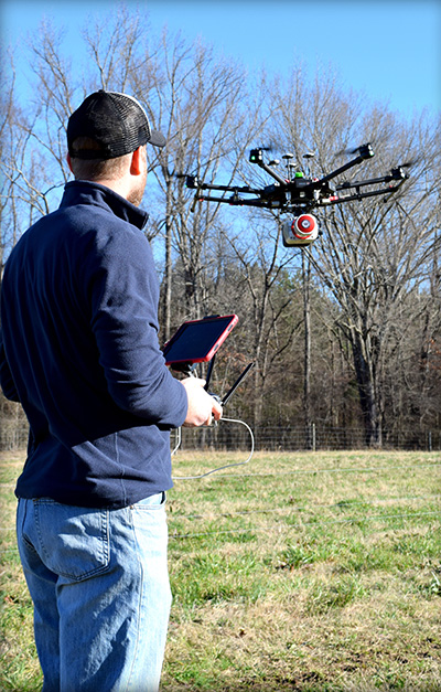
Piloting a lidar-equipped drone. (Photo: Bailie McRae)
How can this type of field survey be improved upon? First, is the product sufficient? Does the field crew reliably capture all the pertinent features? Did they get the location of the trees, buildings, poles and so on?
How many site visits are usually required to complete the average project?
What about the elevation data? Did they capture the drainage and breaklines sufficiently?
As always, the driving question is: Why change? Why abandon well-worn methods in current use?
It has to be for one or more forms of gain: time, money or manpower — which often equates to one or both of the first two terms.
When surveying with conventional equipment such as total stations, levels, and even GPS equipment, the likelihood of failure of a tried and true system is not very great. Comparatively, when using a UAV lidar system, not only are the stakes higher (as the equipment costs more), but the likelihood of an all-out failure is more likely and is definitely more devastating. There is no quick fix if your UAV crashes. It is more likely that the UAV will crash (usually due to operator error) than the lidar system itself will fail.
Facing these concerns, does one embrace a UAV lidar solution or hold to the tried and true?
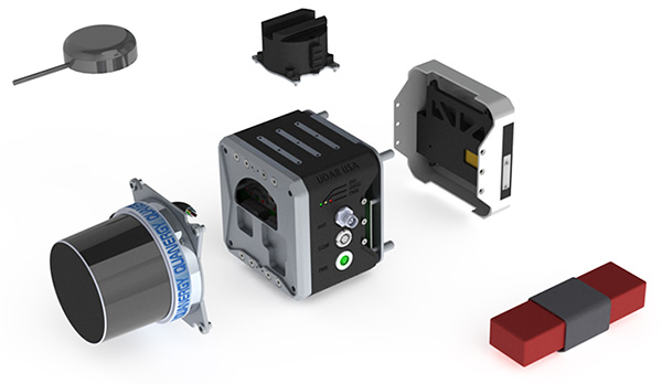
EQUIPMENT: Left to right, from top down: GPS antenna, laser head (Quanergy M8), detachable mount (car & UAV), computer and INS (GNSS receiver + IMU), interface plate, battery. (Photo: Lidar USA)
If it is important to get a heavily wooded 40- to 100-acre job collected and delivered as a surface at 1-foot contour accuracy (or maybe even 0.5 foot) in a single day, then UAV lidar is the tool for the job. UAV lidar can save a lot of field time, eliminate the need for site revisits, capture more data than previously possible, and allow for a better product using more automated extraction tools.
Accuracy. Often the client wants a 3D point cloud, or digital elevation model (DEM), which is not necessarily derived from lidar. If the site has no vegetation present, then an image-based solution should be sufficient.
However, most sites are initially covered with vegetation. In that case, an image solution from some sort of aerial camera will only provide a surface on the top of the vegetation — not what the client wants. While lidar may not be perfect, it can get to within 0.1 to 0.2 feet of the ground surface, in spite of grass or trees. For most initial design surveys, this is all that is required.
Money. Cost is perhaps the topic of greatest persuasion against lidar and in favor of an image-only solution. A lidar system is more expensive than most camera systems, but again the camera system simply cannot collect viable ground data in vegetated areas.
Time. Another factor is the time required to become profitable with the system, and the longevity of the system. In a good economy, it doesn’t take many 40-acre topo jobs to completely pay for a UAV lidar system. Once more, it is about time.
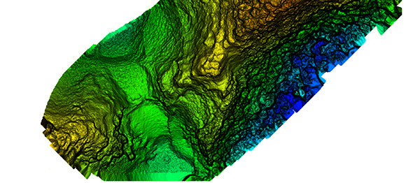
Broad overflight area of the cloud forest. (Image: Lidar USA)
As to product longevity, any new UAV product released today should be just as functional in five years. You may have to upgrade your UAV, but the lidar system will still be good for the jobs we’re discussing.
Lidar collects XYZ and intensity. It does not collect RGB values. This is a strike against lidar. While lidar data can be colorized with imagery captured from a camera on the same system as the lidar, or separately, this is generally discounted as being imprecise (not well aligned). Lidar does not inherently or directly capture color. However, imagery is 2D in nature and does not capture XYZ data.
Imagery can align with the lidar nearly perfectly; it is a matter of a good boresight.
UAV photogrammetry, or image-only solutions are amazing. They provide a wealth of information. They are complementary to and synergistic with UAV lidar.
The advantages of including a UAV lidar solution along with a UAV photogrammetry solution include:
the ability to measure at any time, day or night, in bright light or no light;
rapid surface generation (not instant, but fast);
flat surfaces, vertical walls, overhead structures — everything is collected without difficulty;
power lines, guy wires and so on are all collected directly,
bare-earth collection (multi-echoes and direct collection to ground, not just top of vegetation) is possible;
generally a much wider collection width and fewer flight lines.
Further, lidar can often penetrate dust, fog and mists.
Sensors and Their Issues
Bare earth classified surface of small site. (Image: Lidar USA)
Lidar does require an inertial navigation system (INS) and all of the controlling software. This generally makes the system more expensive. It also makes it able to more rapidly generate the final product.
Inertial Use with Lidar. An INS combines a GNSS receiver with an inertial measurement unit (IMU) and a lot of software and specialized filtering algorithms. It is essentially the central nervous system of a lidar system. The GNSS receiver provides universal timing such that every instrument including the IMU, scanner, cameras and others are all precisely time-stamped. This is key to proper data fusion. The GNSS receiver also provides positioning. The IMU is essential for determining proper orientation (roll, pitch, heading) as well as positioning at an extremely high data rate (2000 Hz) between the recorded GNSS epochs. If a GNSS event is missed (which shouldn’t happen on a UAV) the IMU bridges the gap between epochs. Large gaps can lead to positional drift, but shouldn’t happen on a UAV.
The real-time software maintains satellite lock (coupling with the IMU as necessary), while the post-processing software, using a post-process kinematic (PPK) process, provides the best possible solution of the trajectory. It solves the trajectory forward, backward and over and over with different parameters until it reaches an optimum solution. So it’s not just the hardware that makes the system more expensive, it’s also the software.
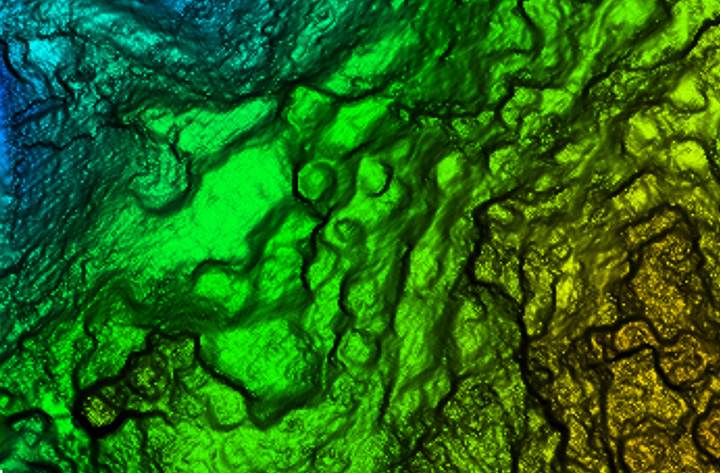
Closer site inspection — notice non-natural occurring mounds. (Image: Lidar USA)
Double Duty? There is some confusion as to the INS on a UAV. Can the INS used to navigate the drone be used for the lidar system as well, to save money? Yes, and no. Yes it can, with the proper integration — however, the INS to navigate the drone is usually far, far inferior to that required by a lidar system. So, No. Also, the lidar system really should be portable from the UAV to a car to maximize use. So the systems need to remain separate, for the most part.
Height and Width. Another UAV sensor issue concerning lidar is often very confusing. Some sensors are only good for 40- to 60-meter flying heights; some are useful to 200 or more meters. Depending upon where you work, this may be of no concern. In the U.S., we are limited to 120 meters above ground level (AGL) in any case. In most areas, being able to fly at 80 to 100 meters AGL is sufficient as long as accuracy and point density are not compromised.
Scan width varies a lot as well. The scan width of the shorter range systems is typically no more than 150 meters of usable area, whereas others can scan 500 meters wide. Consider that most surveys are 40 acres, maybe up to 100 acres, and we find that one flight is all that is necessary even with the least-expensive system. Do you need 500 meters wide? The answer depends upon your business model. If you are doing miles and miles of transmission corridor work, you probably need the greater width.
Ground Accuracy. What matters here is not so much positioning accuracy but point-cloud thickness. This can be difficult to understand and is a worthy subject by itself. The question is whether you can deliver the product you most often are required to deliver with the system. If you deliver 1-foot contour projects, can you achieve this with a 6-centimeter system or do you have to have a much more costly 1-centimeter system? Clearly the 1-centimeter system is much better, but what do you need to deliver?
Intensity is another concern. Most of the less expensive systems don’t do a very good job delivering a “b+w image-like” point cloud; that is, their intensity falls off dramatically with distance. Others do an amazing job. Is this important? Can it be overcome with colorization? If you were doing your work conventionally, would you be delivering an image-like surface? I doubt it. Certainly the intensity is nice to have and the information can be very useful in automated processing, but is it worth the price difference?
Ultimate Test: the Jungle
Recently we undertook an adventure with some explorers in South America, near the city of Jaen, Peru. A crew filming a new TV show for the Travel Channel sought to understand more about the ancient civilization of Chachapoyas, Warriors of the Clouds. Little is known about this race of people because they were conquered by the Incas in the 16th century and shortly thereafter by the Spanish conquistadores.
Our team was to help identify structures in an area called Leymebamba, about four hours’ drive from Jaen, hidden beneath the deep Amazon cloud forests — definitely not a typical North American forest. These forests are not only very dense with vegetation but with cloud cover that is generally at the level of the canopy.
Many centuries after the Chachapoyas have vanished, structural remains are concealed not only by the clouds and the canopy, but buried beneath several feet of dirt and a lot of living and long-since-dead organic matter. Only the most pronounced features can be found by the naked eye or a traditional survey.
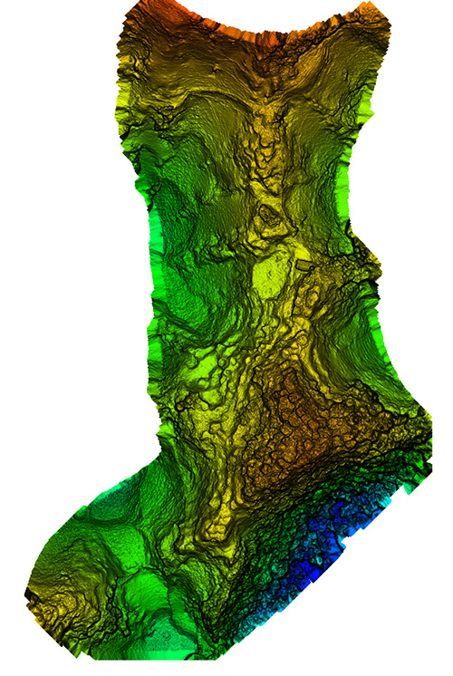
Lidar brings a huge advantage in that it can get a much better approximation of the ground as well as any other hard surface such as walls, fences, trails, buildings and towers. By blanketing an area with dozens if not hundreds of points per square meter, post-processing software can “peel” the living vegetation away from the ground surface. This ground-classified data can then be analyzed by a trained scientist to determine if there are in fact any revelations to be had.
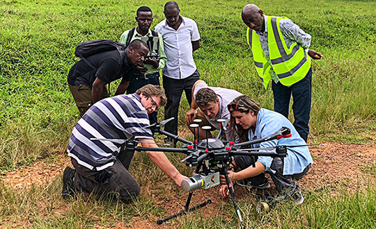
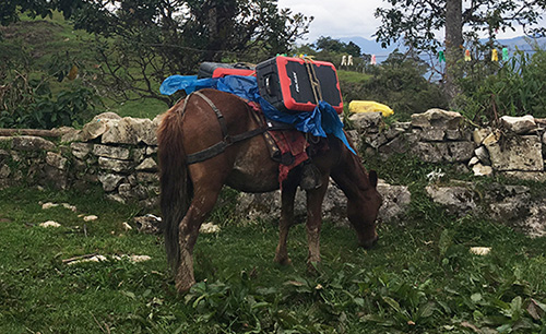
In our case, we were using an A-series high-definition lidar system, best flown at 40 to 60 meters and, in extremely dense vegetation, at 5 to 6 meters/second. Collecting 700,000 points per second enables us to potentially capture more than 400 points per square meter in a single pass. The area we were to scan varied considerably in terrain and had very little to offer that was flat and open. In fact, to get to the site, we had to pack several mountain horses with the UAV, several sets of batteries, and the scanner as they traveled down very steep terrain about 900 feet to the base of the hill to be scanned.
We’ve said we can scan from nearly anything moving, but we’ve never done it from a horse. Well, we weren’t actually scanning, but it was pretty close.
UAV and lidar, bound for the cloud forest. (Photo: Forrest Briggs)
Finding a suitable take-off and landing area posed a challenge. Due to vegetation and terrain, only small areas could be scanned in a single flight, as the vehicle would quickly leave line-of-sight (LOS). While LOS may not be an issue legally in this area, it remains a real concern: we always want our equipment to come home at the end of the mission.
We learned something we hadn’t anticipated along this journey regarding weather. The day would start out around 80° F; around 2 p.m. it would rain, and the rest of the day would close out much cooler. Does this matter? Yes, if you are now wet and cold with several hours ahead of you. It seems there is always some new surprise.
As the area was remote, with no internet access, the existing map data for mission planning had to be downloaded prior to visiting the site. Each lidar mission was preceded by a scout flight using a small UAV to help ensure safety and appropriate flying height per flight line.
Situating the Base. Projects like this always pose dilemmas. Finding a good place for a GPS base station in a cloud forest is no small task. Normally we would put the base station on a known reference point so we can easily join the data with other projects. In this case we didn’t have any such concern. We simply needed an area with a clear view of the sky; usually this means no obstructions 12 degrees above the horizon. However, in a forest and in the mountains, you take what you can get. In our case, we found a rock outcropping and placed the unit on it with no tripod. It didn’t give us the best solution, but it worked.
Ideally we leave the base running for hours to get a good solution. Since we had multiple sites to scan, this wasn’t a problem. All sites were within walking distance of the base, so there was no concern about being too far away and adding more problems to the project. In PPK mode we can easily be 10 or 20 kilometers from the base with no concern.
Other Forest Challenges. In-field processing, far from internet or electrical supply, requires very judicious battery and especially laptop usage. The lack of many things we take for granted can quickly be a show-stopper if necessary (maybe even a phone call).
Even back at the hotel where power was available — don’t count on it. While the film crew and archeologists are eager to see results, everybody has to wait. No power.
Supposedly this is common and only lasts an hour. Three hours pass and everybody goes to bed but the lidar crew.
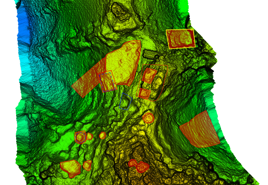
Areas of interest to archeologist — lots of them. (Image: Lidar USA)
Finding the ground should be easy, but a new version of software has been installed. There’s a kink in our plans. Finally after some internet help (a call back home), the right settings are found and the software begins peeling away the vegetation to reveal the ground. The top of each hill (several were scanned) looked like a primitive fortress with 20 to 30 cylindrical structures clearly spread over the top of each site. On one site we identified a tower at least 3 meters in height.
While areas like this could be scanned with a conventional aerial system, collecting much larger areas, the UAV lidar solution offers several distinct advantages. One of these is just a quick recon of the area. Physically being on the ground at the site makes the team much more aware of what is going on. Secondly is the far, far greater density of points and the ability to collect much more off-nadir, allowing for more of the vertical structure to be captured.
In the end, our mission was successful. The UAVs were ported by horseback up and down precarious trails. The lidar worked great. None of the batteries failed. The drones didn’t crash. The archeologists were thrilled with the results, having found several new structures and a tower unknown to them. Once again, UAV lidar proved to be the best tool for the job. Indiana Jones out!
Manufacturers
As both INS sensors and lidar scanners continue to change, this allows us to make quite a variety of configurable systems. For this particular project, we used our Snoopy INS (OEM) with a Quanergy M8 Ultra scanner. The Snoopy INS uses a NovAtel OEM719 GNSS receiver to ensure best performance with GNSS collection. Other options for the INS include the NovAtel STIM300 (Sensonor IMU), VectorNav VN-300 and Trimble Applanix AP family. For scanners we support all Velodyne scanners including the latest AlphaPuck, Quanergy, Riegl and several more. Of course, for cameras there are the ever-popular FLIR, Sentera, PhaseOne and DJI. GPS base stations are not all equal, but most will work as long as they log at least L1/L2 GPS at 1Hz.
JEFF FAGERMAN is a a professional surveyor and certified photogrammetrist. He has a master’s degree in photogrammetry from Purdue University and worked as a photogrammetric software developer at Intergraph before starting Fagerman Technologies. Now known as Lidar USA, the company focuses on mobile lidar aboard UAVs.
Foxcom, a subsidiary of Global Invacom, has launched a solution that enables aircraft ground engineers to undertake 24/7 avionics testing of Inmarsat, Iridium and GPS satellite signals indoors.
The Hangar Repeater Solution enables engineers involved in maintenance, repair and overhaul (MRO) of aircraft to undertake testing 24/7 regardless of the weather, without having to move aircraft in and out of a hangar, as is the current practice.
The dedicated repeater greatly reduces aircraft-on-ground time, work hours and overall maintenance costs, providing a rapid return on investment.
While Inmarsat and Iridium satellite equipment has been deployed worldwide, its use was limited to outdoor, as building structures block satellite signals. Foxcom’s unique and all-inclusive repeater solution provides communication inside buildings or underground without the need for a direct line of sight to the sky. An existing Foxcom repeater can be easily upgraded to add Inmarsat compatibility.
Beyond the aviation sector, GPS, Inmarsat and Iridium repeaters can be deployed across a range of locations and industries, such as underground civil defence and military bunkers, oil rigs and ships and large buildings.
Foxcom launched its first range of repeaters in 2013. Established in 1993, Foxcom specializes in radio frequency over fiber equipment. It is a top supplier to satellite operators, broadcasters and integrators worldwide, with products that offer high performance, bandwidth and reliability.
Point-process mapping links Easter Island statuary to freshwater sources.
By Robert DiNapoli, University of Oregon; Carl Lipo, Binghampton University; Tanya Brosnan and Matthew Becker, California State University, Long Beach; Terry Hunt, University of Arizona; Sean Hixon, Pennsylvania State University; Alex E. Morrison, University of Auckland.
Rapa Nui (Easter Island, Chile) is famous for its elaborate ritual architecture: more than 300 monumental platforms (ahu) and nearly 1,000 monumental, multi-ton anthropomorphic statues (moai). To date, however, we lack explicit modeling to explain spatial and temporal aspects of monument construction.
Photo: Steven Sullivan/Shutterstock.com
In a span of only about 500 years, from the 13th century A.D. to European contact in A.D. 1722 and into historic times, the Rapanui islanders sculpted and erected these famous megalithic statues.
Why? And why were they placed where they stand?
For many years, scholars thought that the island must have supported a larger and more complex society under more prosperous environmental conditions that then collapsed following a self-imposed “ecocide.” In recent years, nearly every major component of this narrative has been shown to lack empirical sufficiency.
In this paper, we use spatially explicit point-process modeling to explore the potential relations between ahu construction locations and subsistence resources, namely rock-mulch agricultural gardens, marine resources and freshwater sources — the three most critical resources on Rapa Nui.
Through these analyses, we demonstrate the central importance of coastal freshwater seeps. Our results suggest that ahu locations are most parsimoniously explained by distance from freshwater sources, in particular coastal seeps, with important implications for community formation and inter-community competition in precontact times.
The island’s marginal ecology limited the food options available to the inhabitants. These environmental constraints could be a key factor in the emergence of monuments on Rapa Nui, such as their role as adaptive responses to environmental uncertainty or as territorial signals of control over limited resources.
We quantitatively modeled how the spatial distribution of ahu is explained by different resources thought to be the focus of competition.
Point-process models (PPM) are a wide class of spatially explicit models that facilitate formal analysis of the relationship between point-patterns and a range of spatial covariates. PPM works by fitting a spatial intensity function to the intensity of an empirical point pattern and finding the values of the predictor variables (i.e., parameters) that best fit the data.
The technique is similar to geographically weighted regression or maximum entropy modeling but has a number of strengths, such as its ability to simultaneously model both first-order and second-order properties in the underlying point-pattern and how these properties may be dependent upon a set of underlying spatial covariates.
Our full paper in the January 2019 issue of PLOS One, an open-access scientific journal published by the Public Library of Science, presents a series of formal models that indicate that if Rapa Nui’s monuments did indeed serve a territorial display function (in addition to their well-known ritual roles), then their patterns are best explained by the availability of the island’s limited freshwater.
Upgrade to MAGNET Collage Web includes with new deliverable options.
Topcon Positioning Group has upgraded its MAGNET Collage Web, a web-based service enabling the sharing and collaboration of UAV and scanning data sets.
MAGNET Collage Web version 1.3 allow operators to work with more types of data with greater flexibility, including the ability to import BIM models, as well as CAD and GIS data.
MAGNET Collage Web and MAGNET Collage desktop software meet the demands of a diverse user-group. The latest update is designed to address an increasing need from the vertical building construction market segment to work in a single-software environment with BIM, scanning and UAV datasets.
“Now operators can view and publish BIM models, along with other data types, directly through the web browser to be sharable with more versatility,” said Alok Srivastava, director of product management. “MAGNET Collage Web can be used to overlay as-built laser scans and design data to visualize proposed changes and detect construction issues. The software supports OBJ, FBX and 3DS formats.”
The upgrade to MAGNET Collage Web also includes new direct publishing functionality for CAD and GIS data files through the browser.
“Operators can now overlay 3D point clouds and reality models with CAD and GIS design data, including support for DXF, SHP, KML, GML and GeoJSON formats,” said Srivastava.
The upgrade to MAGNET Collage Web also introduces advanced sharing controls including the ability to fully customize layer visibility, appearance, window layout, feature selection and camera position.
“The updated customization controls allow operators to share and present their projects exactly the way they mean to with a multitude of viewing options, allowing specific features to be highlighted as necessary,” said Srivastava.
Additionally, MAGNET Collage Web can now be accessed through the Topcon “Blue Bar” that allows direct access to the service from any Topcon website. The universal account and application management toolbar is embedded at the top of Topcon web pages.
Topcon releases upgrade of MAGNET software suite with new features and organization.
Topcon Positioning Group released the newest edition of its suite of software solutions — MAGNET 5.1. The upgrade is packed with new features, modules and support, as well as a reconfiguration of the Office portfolio designed for simplicity.
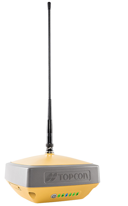
The HiPerVR GNSS receiver. (Photo: Topcon)
New updates to MAGNET Field include support for the new HiPer VR GNSS receiver, a piping and trenching module with new capabilities specifically for the oil and gas segment, as well as the ability to orient and scale a PDF directly on a field controller and set it as a background image.
“The new piping and trenching module greatly improves the COGO, mapping, and exchange functions for in-field oil and gas pipeline design and construction,” said Jason Hallett, vice president of global software business development at Topcon. “Simplified workflows deliver an alignment, profile, and cross-section set for loading into 3DMC for pipe trench excavation. Additionally, customers can now import a PDF drawing as a background image in MAGNET Field. Simply set the insertion point and then rotate and scale by selecting points or lines,” said Hallett.
New additions to MAGNET Office include a reconfiguration of the portfolio, designed for simplicity, integrated workflows and better service plans. The service plans and subscriptions for MAGNET Office now include MAGNET Enterprise, license check-in and check-out, direct email support and an eLearning fundamentals course.
Additionally, the E-commerce user-experience has been greatly improved with a new webstore. Direct email user support is currently offered at this web address.
“The newly optimized product portfolio allows customers to easily select the appropriate Office software product best for their common project demands. The new office structure includes five main products named: project, construction, site, survey and layout, which are consolidated packages of the various MAGNET software services for ease of use and bundling.
“MAGNET Site, MAGNET Construction, and MAGNET Project now include all of the Viasys VDC Modeler and Explorer functionality for infrastructure BIM modeling and visualization, and MAGNET Project adds even more power by including the DynaRoad mass-haul modules Plan, Schedule and Control,” said Hallett.
Additionally, MAGNET Enterprise now offers concurrent login to MAGNET Field, Enterprise and Office with a single set of login credentials.
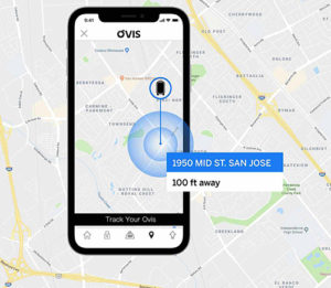
Chinese company Forward X Robotics showed off its Ovis luggage at the 2019 Consumer Electronics Show.
Ovis uses cameras for facial recognition and a movement tracking algorithm to lock in on its owner and stick with her or him at a speed of six miles per hour. Ovis is able to avoid collisions as it makes its way through crowds, according to its maker, which is now producing the suitcase after an IndieGoGo campaign.
Image: Forward X Robotics
The Ovis suitcase comes with a smart wristband that sounds and vibrates if the case gets more than six feet away. Its embedded GPS provides real-time monitoring and tracking via smartphone; the location tracker is in an uncuttable luggage tag.
Similar following suitcases include 90Fun’s Puppy 1, which uses remote control to follow, and the Travelmate Robotics, which provides a removable GPS chip to enable tracking of the bag or anything else of value.
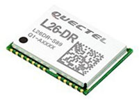
The L26-DR dead-reckoning GNSS module is a multi-GNSS receiver embedded with a dead-reckoning solution to greatly improve positioning accuracy and speed while simplifying customer designs. The dead-reckoning capability ensures the module delivers the highest performance positioning solution available, even when GNSS signals are absent or compromised. Equipped with six-axis sensor MEMs and a powerful GNSS core, the module provides high sensitivity, fast GNSS signal acquisition and tracking with low system integration effort. The L26-DR can acquire and track any mix of GPS, GLONASS, BeiDou, Galileo and QZSS signals.
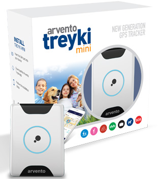
The Arvento Treyki Mini is a compact people and asset tracking device with eight operating modes, including special settings for tracking children (with geofencing) and senior citizens (with an integrated fall sensor). It is also suitable for use in sports, racing and asset management and can be used as an emergency beacon. It has an onboard positioning receiver, and reports its location using an internal GSM/GRPS modem. It can operate for up to seven days from its 900mAh LiPo rechargeable battery before it needs to be recharged. It uses the u-blox ZOE-M8Q concurrent multi-GNSS module, which is able to receive 72 channels simultaneously.
The new Antenova Raptor achieves high accuracy using the L2 1200-MHz GNSS bands. The L2 band combines multi-band satellite signal reception and GNSS correction data, helping to mitigate position errors. The antenna is the latest addition to Antenova’s lamiiANT range of rigid FR4 antennas designed for easy insertion onto a printed circuit board (PCB). It is a GPS single-feed antenna in surface mount (SMD) form, measuring 16.0 x 8.0 x 1.6 millimeters, suitable for small PCBs within all kinds of small electronic devices. Raptor is supplied in tape and reel for ease in high-volume manufacturing applications.
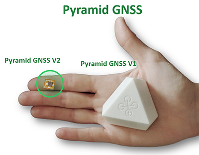
The Regulus Pyramid is a fully functional GNSS receiver fortified with spoofing detection capability. The receiver contains patented technology that enables it to differentiate between real GNSS signals and fake ones generated by an attacker. It is availble both as a fortified GNSS receiver (v1), capable of detecting spoofing attacks, and at the chip level (v2), allowing mobile phones, cars and internet of things (IoT) devices to receive GNSS spoofing protection. A Pyramid GNSS Add-On can be integrated with another satellite receiver to enable spoofing detection capabilities for any GNSS board.
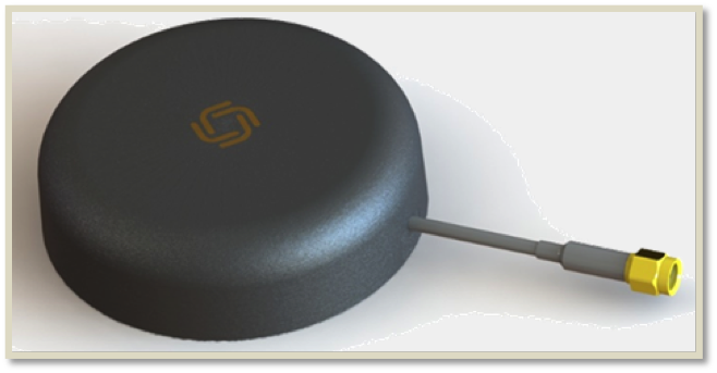
The AGR6302 and AGR6303 GNSS patch antennas are designed for precision dual-frequency positioning. The AGR6302 is capable of receiving L1/L2 bands, and the AGR6303 is capable of receiving L1/L5 bands. They are designed for UAVs, precision agriculture, autonomous vehicles and other applications where precision matters. The AGR6302/AGR6303 active antenna is designed to cover GPS, BDS, Galileo, GLONASS, IRNSS and the QZSS system. It employs a stack four-feeds architecture with hybrid to achieve the multi-band operation, lower axial ratio, wider half-power beamwidth and excellent right-hand circular polarization. It is housed in a compact, industrial-grade waterproof and magnet mount enclosure.
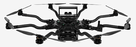
The Alta 8 Pro multi-rotor drone includes waypoint technology to allow preprogrammed movements and autopilot functionality. The Alta Pro flight controller runs open PX4 flight stack for quick and powerful interfacing. The Alta 8 Pro fuses readings from accelerometers, barometer, and GPS to create high-bandwidth height control flight mode. By fusing GPS data with an IMU and barometer, the drone is able to hold position even in difficult weather conditions.
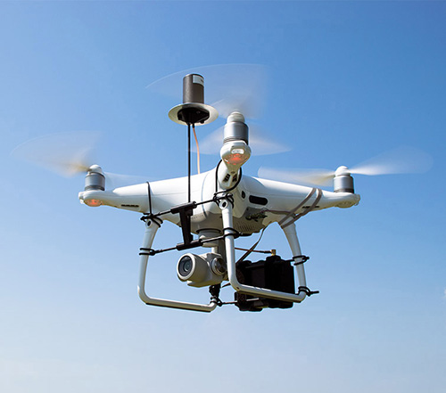
DJI Phantom 4 Pro with Loki PPK system. (Photo: GeoCue)
The DJI Phantom 4 Pro RTK (P4R) drone is now integrated into the AirGon Sensor Processing Suite (ASPSuite). ASPSuite is a post-processing solution for GeoCue’s Loki direct geopositioning system for DJI and other drones. The ASPSuite enables integration of the P4R with third-party L1/L2 GNSS base stations such as systems from Septentrio, Leica, Trimble, Topcon, CHC and others in a high-accuracy PPK workflow. It includes support for engineering-grade survey options such as vertical transforms, creation of and transformation between collection datums and local coordinate systems, application of antenna static and dynamic lever-arm corrections, and full support for Loki direct geopositioning systems.
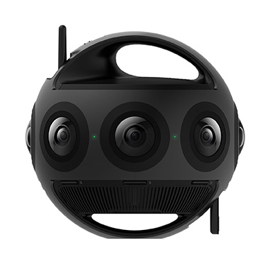
The Insta360 Titan is an eight-lens cinematic virtual reality (VR) camera that captures 360-degree photos and video at up to 11K resolution. The Titan uses eight micro four thirds (MFT) sensors, the largest sensors available in any Insta360 standalone VR camera. It has a GPS signal antenna and a Wi-Fi signal antenna. The sensors maximize image quality, dynamic range, low-light performance and color depth, increasing realism in high-end professional VR capture.
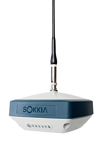
The GRX3 is designed to provide a smaller, lighter and fully integrated GNSS solution to Sokkia’s GNSS receiver line. Its compact and lightweight housing has been tested to meet IP67 certification for protection against harsh weather. The receiver features Sokkia Tilt technology, which includes a nine-axis inertial measurement unit (IMU) and compact eCompass designed to compensate for misleveled field measurements by as much as 15 degrees. UTC technology automatically tracks signals from all available and planned constellations, including GPS, GLONASS, Galileo, Beidou, IRNSS, QZSS and SBAS.
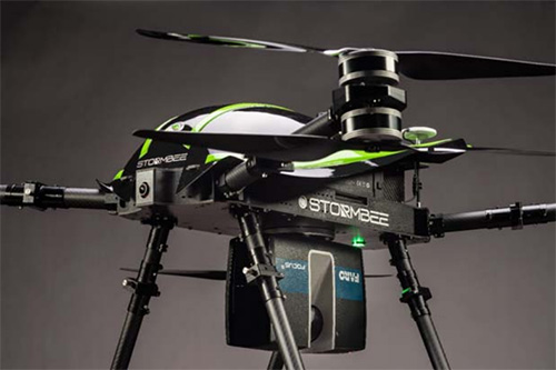
The Faro Focus scanner attached to a Stormbee UAV. (Photo: Stormbee)
The Faro–Stormbee airborne solution includes the Faro Focus laser scanner, the Stormbee S series UAV and the Beeflex software suite. It enables wide-area scanning missions such as highways, train infrastructure and buildings. It allows users to capture complex environments traditionally inaccessible to ground-based scanning. It has no need for control points. Users can create centimeter-level accurate point clouds directly from the in-flight data.
Experts discuss value of automation and new technology
Screenshot: Topcon
The new Infrastructure and Technology series of documentary videos is designed to foster awareness of growing global infrastructure demands and the technology that can help meet them. Experts interviewed include representatives from Intel, SAP, Industry Consultants, Constructech, Solar City and Topcon. They discuss how, by adopting technology, the construction and agriculture industries can increase productivity and help address infrastructure needs now and in the future.The series was filmed globally in the U.S., the Netherlands, the United Kingdom and Germany.
Updated to latest intellicad technology consortium release
Photo: Carlson Software
The specialized drafting package Carlson iCAD 2019 allows technicians to supplement the finished product in their project deliverables. New additions and functions to the iCAD 2019 release are new tool palettes, new 3D solid commands, additional DGN support, and new express tools. iCAD features Google Earth import and export KML/KMZ, standard CAD entities and the drawing inspector tool.Carlson iCAD 2019 has been built with and updated to the IntelliCAD 9.0 engine from the previous IntelliCAD Technology Consortium 8.3 release. IntelliCAD 9.0 supports direct read of DGN files, allowing users to make edits without converting drawing formats, and features a CUI interface for custom workspaces, toolbars and ribbons.
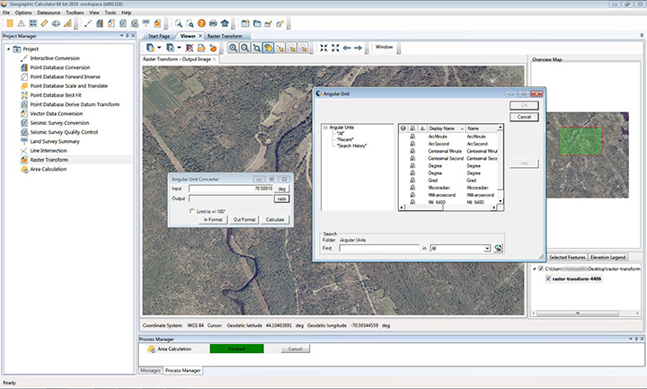
The 2019 Geographic Calculator features a universal copy and paste function, a new angular unit conversion tool, support for NADCON 5.0 and updated seismic survey conversion functionality. The foundation of the calculator’s geodetic data-processing functionality is the embedded GeoCalc datasource, which is continually revised and improved with updates through the online GeoCalc Geodetic Registry. The datasource included in the 2019 release mirrors the most current EPSG database definitions. The calculator’s copy and paste function can be used to quickly capture data for use in a third-party application or to insert new coordinate values in an existing job.
The InvenSense Coursa Drive software is an inertial-aided positioning solution for autonomous vehicle platform developers. It is a high-performance extension of the InvenSense Positioning Library (IPL), which has provided sensor-aided positioning to more than 50 million devices worldwide. Coursa Drive enhances inertial-only vehicle positioning to <0.2 percent of distance traveled, accuracy critical to maintaining decimeter lane-level vehicle positioning in challenging GNSS/perception system environments. Coursa Drive’s inertial navigation system (INS) calibrates using absolute position inputs from either high-accuracy GNSS receivers or from perception-based systems (camera, radar, lidar) with high-definition (HD) maps. In real time, Coursa Drive provides high-rate, 100-Hz delta positions and orientation to the autonomous vehicle system, complementing the lower rate position references from GNSS and perception systems. For non-real-time applications such as HD map creation and maintenance, Coursa Drive’s offline mode reprocesses INS data at two to three times higher accuracy than real-time mode, providing HD map companies alternative position references to verify HD map accuracy, even without GNSS, for up to 60 seconds.
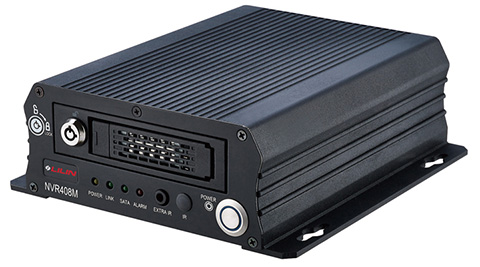
The mobile NVR408M with GPS navigation is designed for use in moving vehicles, remote locations or rugged environments. The rugged compact design works in harsh and demanding conditions to deliver quality video surveillance. Typical applications are in law enforcement or public transportation, using vehicles such as trains, buses, trucks, cars, airplanes and ships. NVR408M is an EN50155-certified product, able to withstand severe vibration and shock and making it suitable for railway applications.
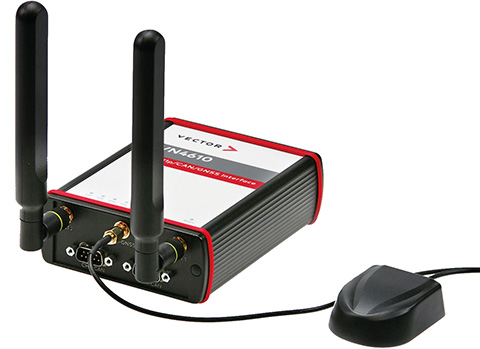
The VN4610 is a powerful interface for accessing IEEE 802.11p and CAN (FD) networks for Car2X/V2X communication using a USB PC connection. The VN4610 provides precise position, time and speed information that can be used by the application as test stimulus or for documentation. The absolute GNSS timestamps can be used to synchronize recordings of distributed measurements for subsequent analysis. The u-blox NEO-M8U supports GPS, GLONASS, Beidou and Galileo — up to three systems simultaneously. The IEEE 802.11p-based dedicated short-range communication (DSRC) communicates in the 5.9-GHz range. The VN4610 supports the unfiltered receiving and sending of IEEE 802.11p frames used for the implementation of Car2X/V2X applications. The received IEEE 802.11p radio-signal-based frames are transferred to the application synchronously to the CAN (FD) messages.
With enhanced ADS-B, SBAS and georeferenced charts
Photo: Collins Aerospace
The Pro Line Fusion avionics upgrade for Pro Line 4-equipped Bombardier Challenger 604 series aircraft has been certified by the U.S. Federal Aviation Administration (FAA). The all-in-one upgrade complies with pending mandates while modernizing the flight experience for pilots. The upgrade includes ADS-B mandate compliance, SBAS-capable GNSS, localizer performance with vertical guidance (LPV) approaches, radius-to-fix (RF) legs, geo-referenced electronic navigation charts, widescreen LCD screens and synthetic vision.