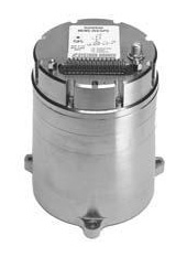
Systron Donner Inertial (SDI) has released an update to its SDN500 digital quartz MEMS GPS inertial navigation system (GPS/INS).
Introduced in 2011, the SDN500 is a platform extension of SDI’s proven, tactical-grade SDI500 IMU.
The modular, compact, 25 in3 SDN500 provides for maximum packaging flexibility in dense systems and delivers accuracies to within 1.0 mrad in attitude, 0.1 m/s in velocity and 3.9 meters spherical error probability (SEP), the company said.
The SDN500-xE product update provides a newer generation JF2 (C/A) Code GPS receiver and tightly couples the 1 PPS GPS signal to the SDI505 IMU synch pulse to improve heading performance and reduce jitter after long periods of operation without dynamic inputs. The specifications for the updated SDN500-xE will remain the same as the current SDN500-xD INS/GPS device.
The SDN500 offers superior tactical-grade performance integrating SDI’s latest generation quartz gyros capable of 0.5°/hr. bias in-run stability and exceptionally low ARW (0.02°/√ hr.), quartz accelerometers delivering 0.5 milli-g in-run bias stability and low VRW (80 µg/√ Hz.), plus high speed digital signal into a tightly coupled GPS-aided Inertial Navigation System for tactical navigation and geo-location applications.
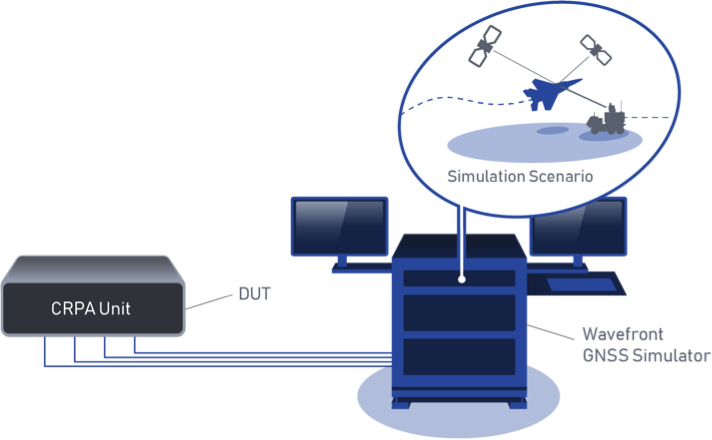
BroadSim Wavefront Simulator at work. (Image: Talen-X)
Talen-X has added the BroadSim Wavefront Simulator to its software-defined platform.
The BroadSim Wavefront further extends the capabilities achieved by BroadSim Anechoic, incorporating support for controlled radiation pattern antenna (CRPA) and multi-element receiver testing.
BroadSim, powered by Skydel SDX, has brought new innovations to the forefront each year to meet the growing needs of Talen-X’s customers, and the new wavefront simulator is the latest advancement.
Its features include:
Phase-coherent simulation
Real-time automated phase calibration
Scalable from 4 to 16 elements
Advanced jamming and spoofing scenarios.
Talen-X engineers are approaching delivery of an operational demonstration unit, as well.
BroadSense Nano
The BroadSense Nano GPS jamming sensor is the newest addition to Talen-X’s BroadSense product line. It has the smallest size, weight and power of any BroadSense product.
The video below features shows a prototype of the Nano, as well as information about its features and a demonstration of the unit reacting to various jamming waveforms in real time.
Four engineers — Dr. Bradford Parkinson, Professor James Spilker, Hugo FrueHauf and Richard Schwartz — were honored for creating the first truly global, satellite-based positioning system. The QEPrize is a prestigious worldwide engineering accolade, a £1 million prize that celebrates the global impact of engineering innovation on humanity.
The 2019 winners were announced Feb. 12 by Lord Browne of Madingley, chairman of the Queen Elizabeth Prize for Engineering Foundation, in the presence of HRH The Princess Royal (Princess Anne) in London.
The four winners will be formally honored at a ceremony later this year; they will receive the £1 million prize and an iconic trophy designed by the 2019 Create the Trophy competition winner, 16 year-old Jack Jiang from Hong Kong.
Why GPS
An estimated four billion people use GPS, and its annual economic value has been estimated to be $80 billion for the U.S. alone. Its applications range from navigation and disaster relief through to climate monitoring systems, banking systems, and the foundation of tomorrow’s transport, agriculture and industry.
The basic tracking required for GPS dates back to the start of the space race, when radio operators tracked Sputnik I on its groundbreaking flight in 1957. Sputnik’s radio signals appeared to drop in frequency as it passed overhead, a phenomenon known as the Doppler shift that allowed the satellite’s position to be determined.
The GPS Creators
The chief architect, Bradford Parkinson, is often called the “father of GPS” after successfully building upon several separate systems to create the current GPS design. Parkinson directed the program and led the development, design, and testing of its key components.
Parkinson insisted that GPS needed to be intuitive and inexpensive, which later made navigation accessible to billions. In 2016, Parkinson was honored with the Marconi Prize. To learn more about his achievements and how GPS began, read this article.
To realize the project, Parkinson recruited James Spilker to design the signal that the satellites broadcast. This type of ranging signal is critical to the success of GPS for civilian use; it is resistant to jamming, precise, and allows multiple satellites to broadcast on the same frequency without interfering with each other.
The 2019 QEPrize trophy, designed by 16-year-old Jack Jiang. (Photo: QEPrize)
Spilker’s team also developed and built the first receiver to process the GPS satellite signals; his delay-locked loop process, used for tracking code division multiple access (CDMA) signals, is essential to GPS accuracy.
GPS receivers rely on accurate timing information, broadcasted from satellites, to determine their position on earth. Each satellite uses multiple atomic clocks — accurate to within billions of a second — to ensure consistent timing. Hugo Freuhauf, then chief engineer at Rockwell Industries, led the development of a miniaturized, radiation-hardened atomic clock — the heart of the GPS satellite. Its accuracy is the backbone of communications systems, power grids, financial networks and other critical infrastructure.
For the GPS program to be affordable, each satellite had to be long-lived. Richard Schwartz, the program manager at Rockwell during the development of these satellites, was tasked with ensuring a three-year life span. His design was resistant to the intense radiation from the upper Van Allen belt, and it also lasted for more than nine years.
Reflections from the Winners
“One of the most important things we had when the project started was a vision of world impact. Without that inspiration, it would have been difficult for us to weather the storms of doing something for the first time,” Parkinson said.
An infographic by the QEPrize organization explains the history of GPS.
“Back in 1978, I made a few drawings that depicted GPS applications that I could personally foresee; they included an automobile navigation system, semi-automatic air traffic control, and wide-area vehicle monitoring, and seem to be rather accurate 41 years later,” Parkinson said. “That said, none of us could fathom the sheer breadth of GPS applications — the many ways that it would become a ‘System for Humanity’.”
In reflecting on the impact of GPS, Freuhauf said, “What surprised me the most was the general response from industry – it blew me away. The world’s tech industry reduced a 40-pound, $100,000 backpack-sized GPS receiver into a fingernail-sized chip receiver that now costs less than $2. Because of that, GPS is everywhere; it is part of the global economic engine and key to global safe-keeping. It’s had an almost unimaginable impact on the globe.”
“It’s hard to imagine what young and creative engineers will come up with next,” Schwartz said. “It’s such a rapidly developing world. That said, in the not too distant future I think I will be able to step into a driverless car, tell the car where I’d like to go, and then sit back and enjoy the ride.”
The Canadian Department of National Defence has awarded a $11.44 million contract to Space Flight Laboratory (SFL) at the University of Toronto Institute for Aerospace Studies (UTIAS) for the development of multipurpose microsatellites to support Arctic surveillance.
Upon successful completion and testing of the prototype, two additional microsatellites will be built to create a small formation.
The UTIAS SFL microsatellites, which are now being developed, will include multiple sensors on a constellation of microsatellites operating in close formation in low Earth orbit to allow for quick and timely detection and identification of surface or airborne targets.
The concurrently obtained sensor observations are expected to improve the reliability of the detection and identification performance, which is not feasible when individual sensors are located on non-collaborating satellites.
On behalf of Defence Minister Harjit S. Sajjan, member of Parliament for York Centre, Michael Levitt announced the contract on Feb 1 during a ceremony at U
“Space Flight Laboratory is honored to assist the Department of National Defence in developing next-generation satellite technology that could be used to monitor Canada’s vital Arctic region,” said SFL Director and Founder Robert E. Zee. “We are pleased that this investment acknowledges SFL as one of the world’s preeminent developers of advanced attitude control and formation-flying technologies for microsatellites.”
Established in 1998 as a self-sustaining specialty lab at the University of Toronto Institute for Aerospace Studies (UTIAS), SFL has built more than 25 nano- and microsatellites with over 95 cumulative years of successful operation in orbit. SFL’s attitude-control technologies have also been applied successfully in several other microspace programs as well, including the 2016 GHGSat-D greenhouse gas emissions monitoring satellite and the 2013-2014 BRITE space astronomy constellation.
As outlined in its defence policy Strong, Secure, Engaged, the Department of National Defence is investing in defence research and development to produce innovative solutions to surveillance challenges in Canada’s North, particularly in the priority areas of Arctic joint intelligence, surveillance and reconnaissance.
Surveillance solutions support the Canadian government’s ability to exercise sovereignty in the North and provide a greater awareness of safety and security issues, as well as transportation and commercial activity in Canada’s Arctic. In addition, solutions achieved under the ADSA program will contribute to joint efforts between Canada and the United States to modernize elements of the North American Aerospace Defense Command (NORAD).
The ADSA S&T Program leverages innovative science & technology expertise from other government departments, academia, industry and allies, to identify, assess and validate technologies in support of air and maritime surveillance, particularly in the North. Through a five-year investment of $133M through to 2020, the ADSA S&T Program is supporting the development of options for enhanced domain awareness of air, maritime surface and sub-surface approaches to Canada, in particular those in the Arctic.
A SpaceX Falcon 9 rocket lifts off from Space Launch Complex 4E at Vandenberg Air Force Base, California, Jan. 14. (Photo: SpaceX)
Starting this month, the inspector general for the U.S. Pentagon will be reviewing how SpaceX’s rockets became certified to launch payloads for the U.S. Air Force, a decision made in May 2015.
“Our objective is to determine whether the U.S. Air Force complied with the Launch Services New Entrant Certification Guide when certifying the launch system design for the Evolved Expendable Launch Vehicle-class SpaceX Falcon 9 and Falcon Heavy launch vehicles,” wrote Michael J. Roark, deputy inspector general for Intelligence and Special Program Assessments, in a Feb. 11 memorandum to the Air Force.
In April 2016, the U.S. Air Force awarded SpaceX the first competitively sourced National Security Space (NSS) launch services contract in more than a decade, when the company won the GPS III Launch Services contract, fixed at $82,700,000.
Less than one year later, SpaceX was awarded a second contract for launch services to deliver a GPS III satellite to its intended orbit.
The evaluation will be performed at the Space and Missile Systems Center, a unit of Air Force Space Command, headquartered at Los Angeles Air Force Base in El Segundo, California. Additional locations may also be identified as part of the audit.
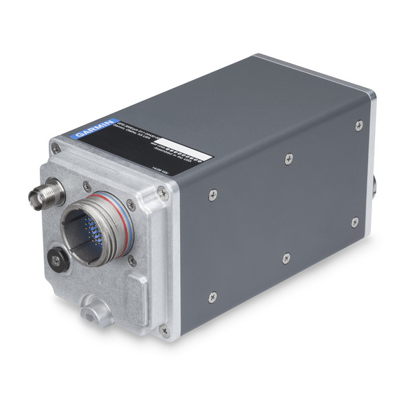
Garmin International Inc., a unit of Garmin Ltd., has launched the GPS 3000, a high-integrity GPS position sensor that interfaces to existing avionics to help meet Automatic Dependent Surveillance-Broadcast (ADS-B) Out requirements.
Also, targeting the air transport and defense markets, the GPS 3000 is designed as a WAAS/SBAS position source for select Flight Management Systems (FMS).
Aircraft that are eligible to utilize the GPS 3000 as an ADS-B position source include the Embraer E135/E145 and the Legacy 600/650. Supplemental Type Certification (STC) for the GPS 3000 in these aircraft is currently available from FTI Engineering, in cooperation with Atlas Air Service in Germany, and can be installed throughout the entire Garmin dealer network.
“Garmin continues to lead the industry with the most fielded ADS-B solutions that span all segments of aviation, including a wide-range of commercial, defense, regional and business aircraft,” said Carl Wolf, vice president of aviation sales and marketing. “We are thrilled to provide these aircraft with a solution that is cost-effective and is an easy to install alternative to the existing avionics manufacturer’s service bulletin.”
A rugged, stand-alone and certified Wide Area Augmentation System (WAAS)/Satellite-Based Augmentation System (SBAS) GPS, the GPS 3000 meets DO-160 and DO-178B standards and is designed specifically for the harsh environmental conditions encountered by commercial aircraft.
This compact and remote-mount solution utilizes enhanced WAAS/SBAS GPS satellite signals to provide precise position data through a standard interface. It also meets applicable high-integrity ADS-B position source standards, including TSO-C145d Class 3, the company said.
The GPS 3000 is also designed to interface with select FMS to support GPS guidance throughout terminal, enroute and approach navigation. When configured appropriately, the GPS 3000 is capable of providing position information to an existing FMS to meet requirements for Required Navigation Performance (RNP) and can support GPS-based vertical approach navigation, such as Localizer Performance with Vertical (LPV) approach guidance.
European Aviation Safety Agency (EASA) STC of the GPS 3000 in the Embraer E135/E145 and Legacy 600/650 is available from FTI Engineering, in cooperation with Atlas Air Service, as well as Garmin dealers. FAA validation of the STC is pending.
The latest software release for the SLAM-based NavVis M6 Indoor Mobile Mapping System (IMMS) automatically detects and removes point cloud artifacts, including moving objects in static scenes, the company said.
This image shows what an object looks like where the laser beam has hit an edge, before and after the algorithm has been applied. (Image: NavVis)
NavVis is a global provider of indoor spatial intelligence solutions. The latest IMMS release removes artifacts from point clouds during the post-processing of scan data.
Fringe points and dynamic objects are two common types of point cloud artifacts that affect all 3D laser scanning devices. Fringe points arise when a laser beam hits the edge of an object as well as its background. This scattered beam ultimately appears as a “fringe” around the edge of the object in the point cloud.
The second type of point cloud artifact results when dynamic objects, such as humans walking through a scan, are captured by the laser scanner and then appear as artifacts in the point cloud.
A point cloud before and after the algorithm has been applied to a dynamic object. (Image: NavVis)
According to the company, the NavVis M6 IMMS is a simultaneous localization and mapping (SLAM)-based system that uses laser scanners to capture a high volume of measurement points of an environment. As SLAM-based mobile mapping systems move through the environment while scanning it, objects are observed from multiple different angles and positions.
With the latest software update, the algorithms applied during the post-processing of scan data use those multiple observations to detect whether measurement points actually exist in the physical space. If it is determined that the point does not exist and is instead resulting from the laser beam hitting an edge or an object moving through the space, this point is automatically removed.
The result is a much cleaner, crisper point cloud that requires less clean up time in point cloud editing software and that is easier to use for applications such as BIM modeling, the company said.
“We have been working hard to develop a very precise SLAM technology that significantly improves the quality of point clouds captured by a mobile device,” said Georg Schroth, NavVis co-founder and CTO. “As this latest software feature shows, SLAM offers a lot of potential for laser scanning and AEC professionals who are looking for technology that not only speeds up the capture of data but also delivers high quality point clouds. We see a lot of potential in this technology and look forward to sharing future innovations.”
Airbus Defence and Space and Hisdesat Servicios Estratégicos S.A. have generated the first joint TerraSAR-X/PAZ radar interferogram. This milestone demonstrates the missions’ capacity for cross-sensor interferometry, whose processing is among the most challenging.
Interferograms are typically used to derive the topographic elevation and deformation of the Earth’s surface, and are created using at least two different images acquired at different date. This flattened cross-sensor-interferogram has been created from a mixed image pair with four days’ temporal separation acquired by TerraSAR-X and PAZ (StripMap scenes from Nov. 22-26, 2018). The area covers the oil and gas production site Burgan (Kuwait) and parts of the Persian Gulf. The oil field is the world largest sandstone oil field with the total surface area of about 1,000 km².
As PAZ is positioned in the same orbit as TerraSAR-X and TanDEM-X and features exactly identical ground swaths and acquisition modes, they all three form a high-resolution SAR satellite constellation, jointly exploited by Hisdesat and Airbus. With the launch of PAZ, the observation repeat cycle has been divided by half, which improves the monitoring of fast ground deformation phenomena that can endanger lives and infrastructures.
“This is a major step towards achieving the implementation of our TerraSAR-X/PAZ radar constellation,” said Hanjo Kahabka, head of production and radar constellation manager at Airbus. “The level of accuracy obtained with this interferogram is a guarantee for our customers to continue to rely on the high quality standard we have set with TerraSAR-X and TanDEM-X, but with an improved monitoring capacity,”
“In Hisdesat we are very proud of reaching this milestone. Interferometry is one of the most technically demanding applications, and thanks to this successful joint exercise with Airbus we have not only demonstrated the top performance of our PAZ satellite but its full compatibility with TerraSAR-X and TanDEM-X,” said Miguel García Primo, CEO at Hisdesat. “Now operation in constellation can become a reality and we will be able to provide to our customers full set of images and services with the constellation.”
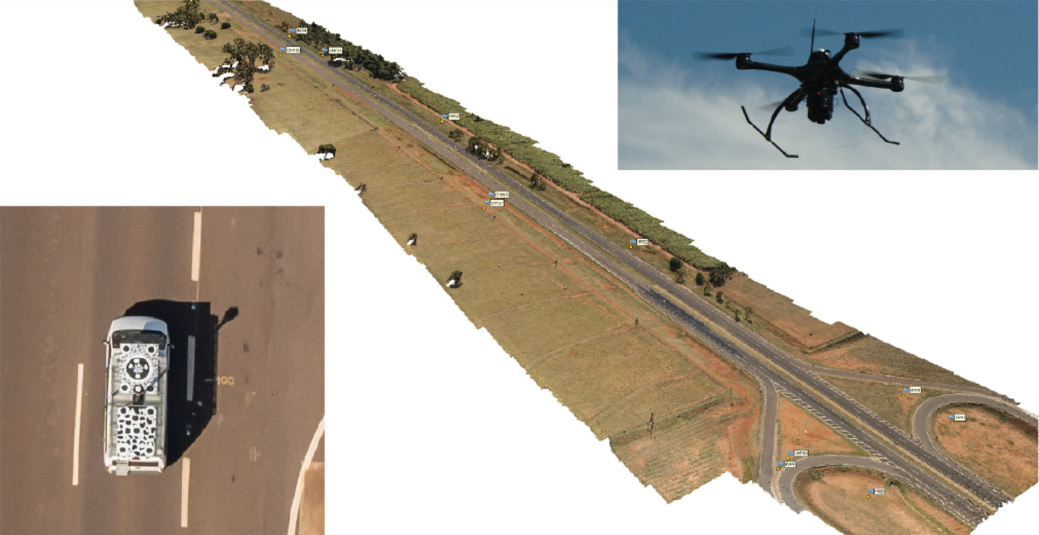
Kinematic Ground Control point for UAV photogrammetry: A dynamic duo of UAV and mobile van combine to deliver the accuracy of conventional methods with only 2+2 ground control points at the ends of the corridor.
By Ismael Colomina, Pere Molina and Roberto da Silva Ruy
A Brazilian and a Spanish company, ENGEMAP and GeoNumerics respectively, have finalized the accuracy evaluation of a mission conducted with the latter’s mapKITE technology on a Brazilian motorway in 2018.
The goal of the evaluation was to confirm the advantages of the mapKITE method and its kinematic ground control point (KGCP) concept over conventional corridor mapping methods.
The mapKITE and the conventional method delivered comparable accuracy results — the difference being that the latter requires a dense set of surveyed ground control points (GCPs) while mapKITE does the job with almost no GCPs.
For this purpose, a 4-kilometer segment of the Rodovia Raposo Tavares in São Paulo state was populated with a set of 37 evenly distributed, signalized, accurately surveyed ground points. The set was divided into two subsets of 23 GCPs and 14 ground check points (GChPs) — the ground truth — respectively. The 4-km road segment was also covered by 189 drone images and their corresponding 189 KGCPs. The image set was processed as a conventional aerial corridor block:
with the integrated sensor orientation (ISO) method in a 23 GCP + 14 GChP configuration, and
as a mapKITE aerial corridor block in a 4 GCP + 14 GChP + 189 KGCP configuration.
The two processes produced similar accuracy results: mean (μ), empirical standard deviation (σ) and root mean square (rms) error of the photogrammetric determination of the horizontal (EN) and vertical (h) coordinates of the GChPs against the ground truth. (All units are stated in millimeters.)
The mapKITE configuration uses only four GCPs (two at each end of the road segment) in contrast to the 23 GCPs of the conventional method. Nominal flying height of the drone was 120 meters above ground, producing an average ground sampling distance (GSD) of 2.3 cm. Forward image overlap was 80% resulting in a base-to-height ratio of 0.157.
MapKITE is a GeoNumerics patented method for 3-dimensional corridor mapping that combines the two latest geodata acquisition methods, terrestrial mobile mapping and aerial drone-based mapping. MapKITE is a tandem terrestrial-aerial mapping method and system composed of:
a terrestrial mobile mapping system (land vehicle and sensors) carrying
an optical metric target on its roof;
a drone aerial mapping system; and
a real-time virtual tether and post-mission software.
In a mapKITE mission, the drone follows the land vehicle, and thus the vehicle target becomes a kinematic ground control point visible and measurable on each image. It is a high-accuracy, high-resolution Earth observation method. MapKITE combines the advantages of mobile land-based encompassing images and 3D point clouds. MapKITE combines the advantages of mobile land-based (manned) and aerial drone (unmanned) mapping systems.
GeoNumerics (Castelldefels, Spain) is a research and development company specializing in geomatics and accurate navigation.
ENGEMAP (Assis, Sao Paolo, Brazil) is one of the largest and oldest mapping companies in Brazil. It has more than 100 employees, three aircraft, two mapping land vehicles, a number of rotary- and fixed-wing drones and a record of accomplished mapping and cadastral projects. ENGEMAP is officially authorized by the Brazilian Ministry of Defence (MD) and the Brazilian Department of Airspace Control (DECEA) to conduct mapKITE commercial flights in Brazil.
MANUFACTURERS
The mapKite campaign was conducted with a Sensormap SMM terrestrial mobile mapping system and a UAVision UX Spyro drone equipped with a NovAtel OEM2 GNSS dual-frequency receiver with a Maxtena antenna and a Sony α7R camera with a 25-mm camera constant lens. The INS/GNSS system in the Terrestrial Vehicle was a Span-CPT (Novatel) including dual-frequency antenna and DMI wheel sensor.
ISMAEL COLOMINA is chief executive and chief scientist at GeoNumerics. He has a Ph.D. in mathematics from the University of Barcelona.
PERE MOLINA is advanced applications program manager at GeoNumerics. He holds a master’s degree in mathematics from the University of Barcelona and a master’s in photogrammetry and remote sensing from the Institute of Geomatics, Catalonia.
ROBERTO DA SILVA RUY is technical manager at ENGEMAP. He has a Ph.D. from the Universidade Estadual Paulista.
New developments in antenna technology empower the final positioning solution with better accuracy and reliability. Leading experts discuss the technology advances producing greater user benefits.
The increasing prevalence of both intentional and inadvertent jamming, new wider bandwidths, and the significance of antenna phase-center variation all bring changes to the dynamic and evolving antenna sector.
Javad Ashjaee (Photo: Javad GNSS)
Javad Ashjaee
President & CEO, JAVAD GNSS
Advanced filtering techniques enable our antennas to defend against jammers and spoofers and to inform users with the details of these intrusive actions when they are detected.
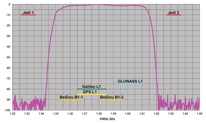
Near-Band Interference. The J-Shield is a robust filter in our antennas that blocks out-of-band interference, in particular such signals that are near the GNSS bands like the LightSquared/Ligado signals. The graph below shows the protection characteristics of the J-Shield filters. It has a sharp 10-dB/KHz skirt that provides up to 100 dB of protection. It makes the precious near-band spectrums available for other usages and protects GNSS bands now and in the future.
In-Band Interference. Our in-band protection digital filter protects against in-band interference like harmonics of TV and radio stations when you get close to them, or against illegitimate in-band transmissions. Our in-band interference protection is based on the 16 adaptive 80th-order filters. Advanced interference mitigation (AIM) filters can be combined in pairs for complex signal processing. This filter can simultaneously suppress several interference signals.
Graph: Javad GNSS
The 16 finite impulse response (FIR) AIM filters can be combined in any number in chain. Each filter is a 255-order FIR filter. It can be used to suppress the stationary interference signal in programmable area (compare with adaptive AIM-filter) or for spectrum shaping. To have more suppressing areas or more aggressive suppressing, one can combine FIR AIM serial.
Neil Gerein, Portfolio Manager, NovAtel. (Photo: NovAtel)
Neil Gerein
Director, Product Management, NovAtel
At NovAtel we often say, “accuracy is addictive,” and to meet increasingly demanding accuracy and reliability requirements it is vital to concentrate on the antenna. After all, the antenna is the first in a long chain of key technologies that the GNSS signals must pass through to create a position, navigation and timing solution.
All modern GNSS transmit on multiple frequencies, with wide bandwidth signals, requiring antenna elements and integrated low noise amplifiers (LNAs) that operate across these frequencies. The challenge is to design the antenna element and LNAs for symmetric radiation patterns across all frequencies while minimizing multipath, phase center offset (PCO) and phase center variation (PCV). The result is better carrier-phase measurements, and therefore more accurate solutions in real-time kinematic (RTK) and PPP applications.
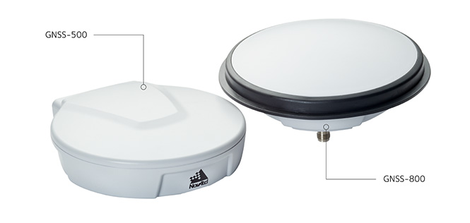
Photo: NovAtel
Since 2016 the Radio Equipment Directive (RED) has been in effect, and all GNSS receiver systems sold into the European Union must be compliant to the standard, including adjacent-band compatibility and spurious emissions testing. RED compliance is an end-to-end system test, where the filtering within the antenna must be analyzed in concert with the filtering capabilities of the connected GNSS receiver to meet the requirements. The antenna performance therefore becomes critical to any GNSS receiver system that is intended to be sold within the EU.
Gyles Panther, president and CTO, Tallysman Wireless. (Photo: Tallysman)
Gyles Panther
President and Chief Technical Officer, Tallysman
A fact often not appreciated is that the performance of a GNSS antenna is commonly the limiting factor in system accuracy. Digital signal algorithms in the receiver are helpful, but if the signal delivered by an antenna is less than optimum, the receiver cannot compensate.
Precision GNSS systems typically rely upon resolved wavelength ambiguity measurements, combined with ephemeris and clock corrections to determine signal time of flight. In real-time kinematic (RTK) and precise point positioning (PPP) receivers, the basis for this measurement is phase locked tracking of received satellite signals. Thus an over-arching measure of antenna performance in the specific application conditions is the proportion of the time that phase lock is maintained by the receiver.
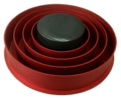
The VeraChoke GNSS antenna. (Photo: Tallysman)
All this provides for an unprecedented level of accuracy, with precision antennas now more akin to the ends of a tape measure than providing a simple GNSS “fix.” To this end, key parameters include a best possible G/T ratio, high multipath rejection, excellent axial ratio, high front-back ratio and minimal phase-center variation (PCV), all with high uniformity in the azimuth — altogether a very demanding design task.
Combining these parameters to provide exquisite accuracy, the Tallysman VC6100 choke ring antenna has less than 1 millimeter PCV when combined with absolute calibrated corrections data, whilst the lower cost VP6000, with its less complex installation, can be used without corrections data and still be within a millimeter or two of the truth compared to its more precise cousin.
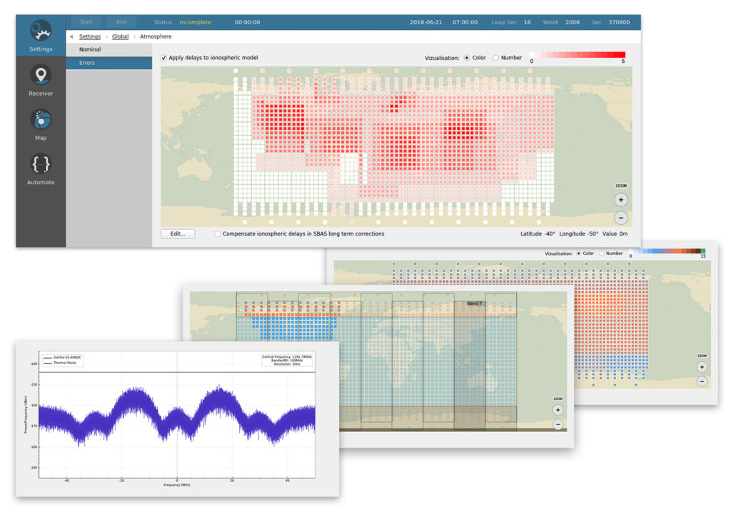
Skydel Solutions has updated its SDX GNSS simulator to version 19.1. The new version adds Galileo AltBOC signal generation, new atmospheric errors, SBAS improvements and SV antenna patterns.
Galileo AltBOC. SDX now supports Galileo AltBOC as a new GNSS signal type. Current SDX users licensed with the Galileo E5 signal will be able to generate 8 Phase Shift Keying (8-PSK) constant envelope AltBOC after upgrading to SDX 19.1.
The signal can be generated by selecting both Galileo E5a and E5b in the output – signal selection panel.
A montage of screenshots showing the various updates. (Image: Skydel)
Atmospheric Delays and Improvements to SBAS. Version 19.1 adds a new error type to all SDX users: atmospheric delays. These errors can be compensated with SBAS for SDX licensees with the SBAS option installed. The SBAS message now broadcasts ionospheric error corrections.
Three new interfaces help create, manage and use these error values in simulation scenarios.
Atmospheric Errors (Settings : Global). This panel enables users to review and edit the ionospheric delay values for any SBAS Ionospheric Grid Points (IGPs) . The map view can be navigated (pan and zoom) much like the map panel of the simulation. The edit button brings up an IGP editor used to assign the points values or increase their current value by a set amount.
Since the number of points in the grid is fairly large, the user interface works with a selection of points, allowing users to add or remove the current selection in order to quickly work your way around the whole map.
Atmospheric errors are available to all SDX licensees with the 19.1 upgrade.
Ionospheric Masks (Settings : SBAS). SDX users with the SBAS option can use this new interface to assign the true/false value for each point of the different SBAS bands, per service provider. It reuses most of the paradigm of the aforementioned atmospheric error pane.
Ionospheric GIVE Indicators (Settings : SBAS). Using a similar map interface as the two previous panels, the GIVEI (GIVE Indicators) panel enables you to provide the GIVE Indicator values for each IGP that is configured in the mask, per service provider.
The grids created or modified with these new options can all be saved and imported back into future SDX scenarios.
New GNSS Satellite Antenna Patterns. Also new in SDX 19.1 is the possibility to add user-defined antenna patterns to GNSS satellites. These new antenna pattern options show SDX’s flexibility by allowing any user-defined antenna pattern to be applied to any satellites in any GNSS constellation.
This can prove especially useful for scientists and engineers working with space vehicles, due to their unusual orientation when compared to surface vehicles. High-Earth-orbiting spacecraft benefit from the side lobes of GNSS satellites to improve navigation performance. In fact, when tracking the signal from side lobes, the number of visible satellites is drastically increased, and the precision can improve from the kilometer to the meter level.
In addition, the new antenna patterns can be a potent tool in the context of research projects that experiment with user-defined GNSS SV Antennas.
SV antenna patterns in SDX. SDX now allows you to create, define, and manage antenna patterns for GNSS satellites using an interface very similar to the one we introduced for vehicles in SDX 18.10. As with that release, the various patterns are organized into antenna models that can be named, managed, exported, and reimported back into other simulation scenarios.
The user interface has also been improved. Read more about the changes in Skydel’s blog.
Are drones (UAVs) a disruptive or constructive technology for high-precision mapping that yields practical, actionable results for the end user/customer?
Ismael Colomina
“More constructive than disruptive. Drone mapping is opening new markets that, to a large extent, were not serviceable by conventional manned flights. On the other hand, the profound changes — and crisis — in the mapping business were not produced by drones.” Ismael Colomina GeoNumerics
Jean-Marie Sleewaegen
“Drones have dramatically reshaped the surveying and mapping industry. Combined with reliable positioning and recent advancements in high-resolution cameras, photogrammetry and computer vision, drones now enable high-accuracy mapping faster and at much lower cost than conventional mapping techniques.” Jean-Marie Sleewaegen Septentrio
Jules McNeff
“Drones can be constructive augmentations to high-precision map products because of their ready access to diverse locations. Drone imagery can document real-time physical changes that affect mapping applications during natural disasters or other events — but images alone aren’t maps without a geo-referenced grid such as the U.S. National Grid.” Jules McNeff Overlook Systems Technologies Inc.
Other members of the EAB
Tony Agresta Nearmap
Miguel Amor Hexagon Positioning Intelligence
Thibault Bonnevie SBG Systems
Alison Brown NAVSYS Corporation
Clem Driscoll C.J. Driscoll & Associates
John Fischer Orolia
Ellen Hall Spirent Federal Systems
Terry Moore University of Nottingham
Bradford W. Parkinson Stanford Center for Position,Navigation and Time