Author: GPS World Staff

  • Augmented Reality for Precision Navigation: Enhancing Performance in High-Stress Operations

    Augmented reality delivers two important military capabilities to the warfighter: situational awareness and precision piloting capabilities, both key to survival on the battlefield. Look-ahead drive-to-position, based on accurate GPS positions, extends the importance of GPS to high-speed operation or very close maneuvering situations where humans cannot cycle through a chart or map display, then place themselves in the real world to make maneuvering decisions.

    By Thomas Zysk, Jeffory Luce, and James Cunningham

    Augmented reality (AR) is a concept in daily use in the modern technology vernacular. In one popular form, AR enhances football broadcasts with overlaid information such as the first down line. A much more robust capability for application in high-performance navigation systems uses accurate GPS and heading sensors to geographically register a virtual world accurately over a real-world, real-time view. In a military context, AR can provide critical context to situational awareness.

    AR for military use was originally developed as a maritime equivalent to the aviator’s heads-up display. Evaluations using a task-load index function showed a 342 percent improvement in side-task operator performance when using AR. Operators do not have to make the mental conversion from 2D (map or chart view) to 3D real-world view. This translation is where errors can be made in high-stress scenarios and forms the root cause of many accidents. AR provides a game-changing capability to enhance warfighter performance when it matters and is invaluable during high-stress, dynamic operations.

    Photo approved for release by MC1(AW/SW) Michael W. Pendergrass, Fleet Public Affairs Center Atlantic, (757) 444-4199 ext 322
    Amphibious assault vehicle (AAV), U.S. Marine Corps.

    In this navigation context, AR was developed for use in low-visibility situations, such as navigating in dense fog or at night during lights-out missions. The technology can provide a visual depiction of critical points of interest, regardless of real-world visibilities. AR provides the means to integrate sensors and supporting geographic information system and related systems into a cohesive visual display that overcomes environment limitations or such things as closed-hatch operations on military vehicles.

    AR delivers two important military capabilities to the warfighter: situational awareness and precision piloting capabilities, both key to survival on the battlefield.

    Situational Awareness. Any information with a geographical registration component can be overlaid on the real-world view in a single composite display format. This can track data, threat locations, friendly-force locations, obstacles, and safe havens; the list grows each day. This information adds immensely to the operator’s understanding of the environment. This fused information, over a real-world, real-time view, is functionally an enhanced Common Operational Picture (COP). Operators can be more cognizant of the tactical situation day, night, or in any visibility condition.

    Precision Piloting. The faster one drives in an automobile, the further down the road one must focus to stay on the highway. AR provides this look-ahead drive-to-position based on accurate GPS positions. This extends the importance of GPS to high-speed operation or very close maneuvering situations where humans cannot cycle through a chart or map display, then place themselves in the real world to make maneuvering decisions.

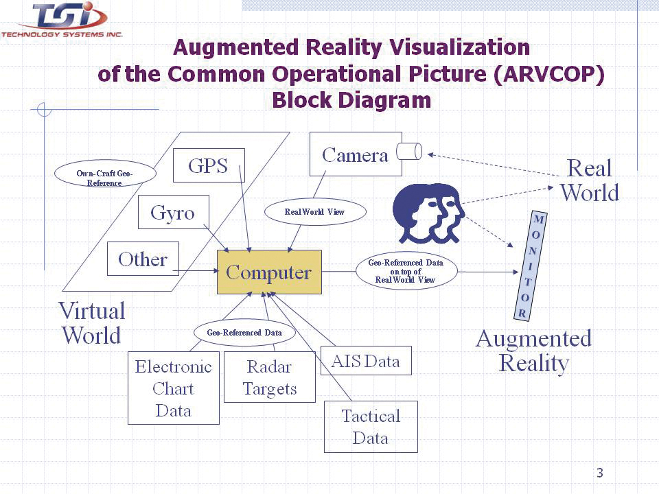
    AR enables a rich suite of functions supporting the access and maintenance of a COP, and demonstrated maneuver accuracy. For the Augmented Reality Visualization for the Common Operational Picture (ARVCOP) system, any situational awareness information available can be overlaid on the real-world view in a clear and organized way. Operators do not have to go through the process of translating what they see on a map to what they see in front of them, a translation process that often incurs error. AR then delivers this to warfighters through a human-cognition friendly, integrated display of sensor data and geographically registered overlays, as Figure 1 illustrates. The AR view is shown along with a two-dimensional view on the right side of the display.

    Photo: Thomas Zysk, Jeffory Luce, and James Cunningham
    Figure 1. ARVCOP display example.

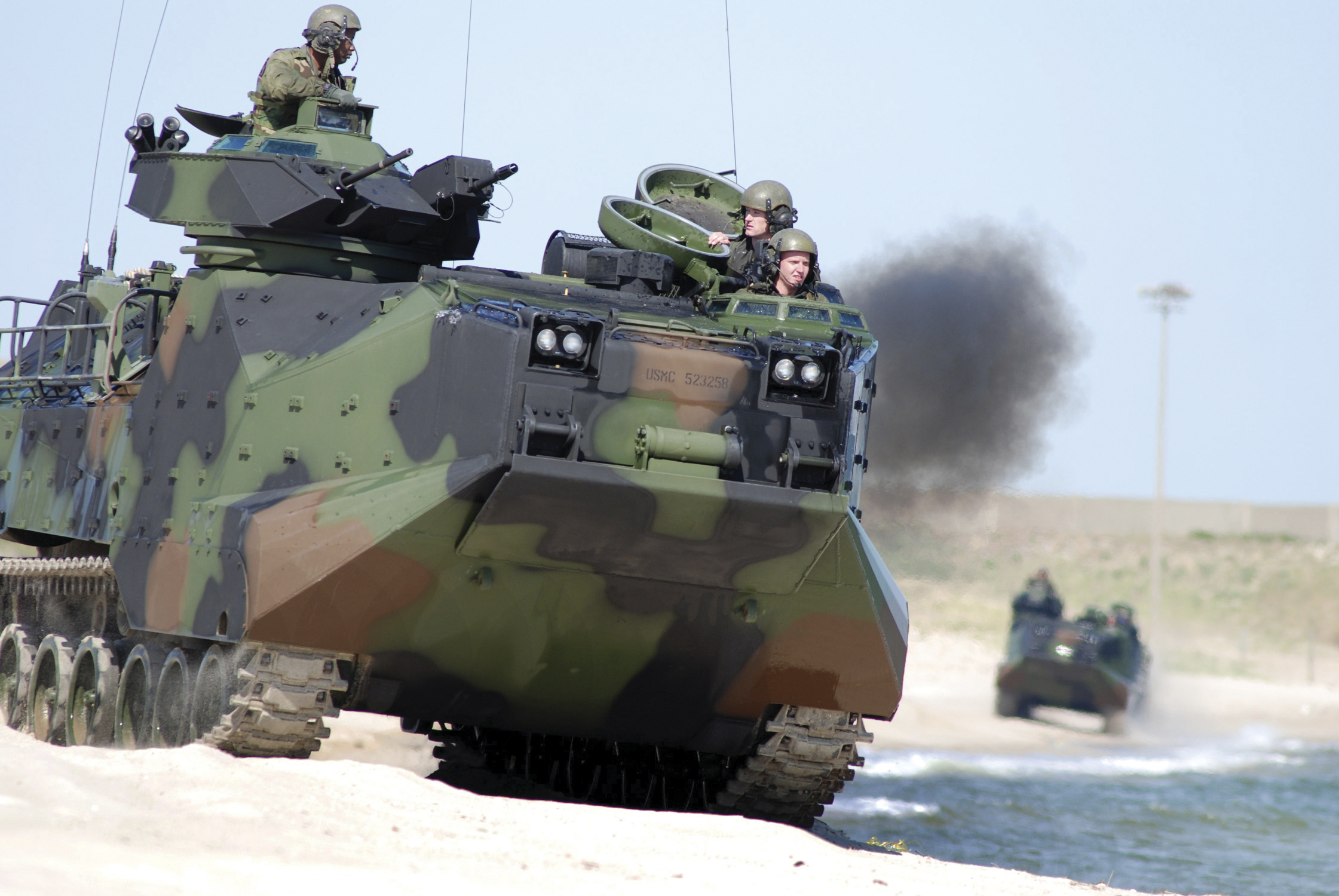
    Developed by the Office of Naval Research with industry partner Technology Systems Inc., ARVCOP provides a human-machine interface that can magnify the effectiveness of precision positioning. In this article, we discuss how AR is utilized in this context and the results of testing AR precision-navigation systems aboard Marine Corps amphibious assault vehicles (AAVs, see photo) on the beaches of Marine Corps Base Camp Pendleton, California.

    Precision piloting, or driving accuracy, is achieved by providing the operator a point toward which to drive that is in relation to the current position. Testing showed that looking ahead or driving to a point forced the operator to self-correct for the effects of wind, waves, and current.

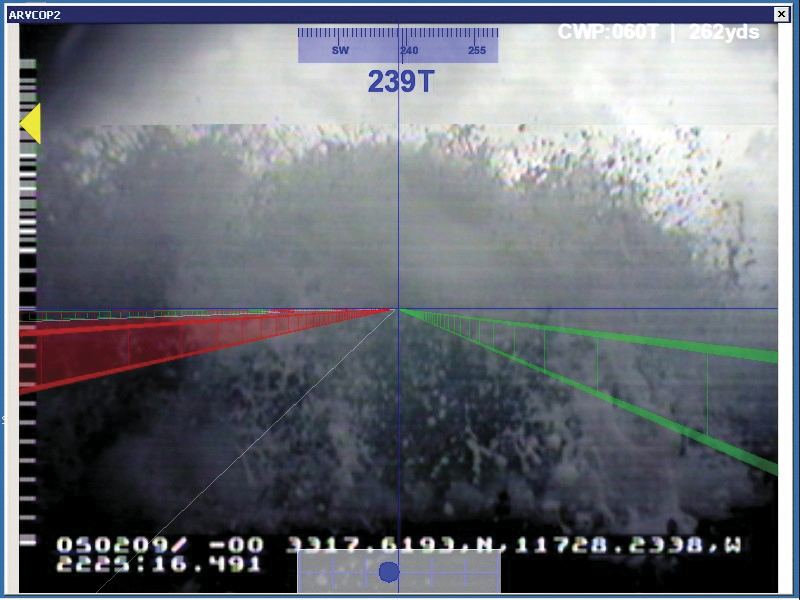
    AR is exemplified by a software application that combines real-time video imagery with virtual images to provide a new dimension in navigation piloting accuracy. Figure 2 is an AR display on a ferry boat showing the navigational route marked by rails.

    Photo: Thomas Zysk, Jeffory Luce, and James Cunningham
    Figure 2. Real world with augmented reality.

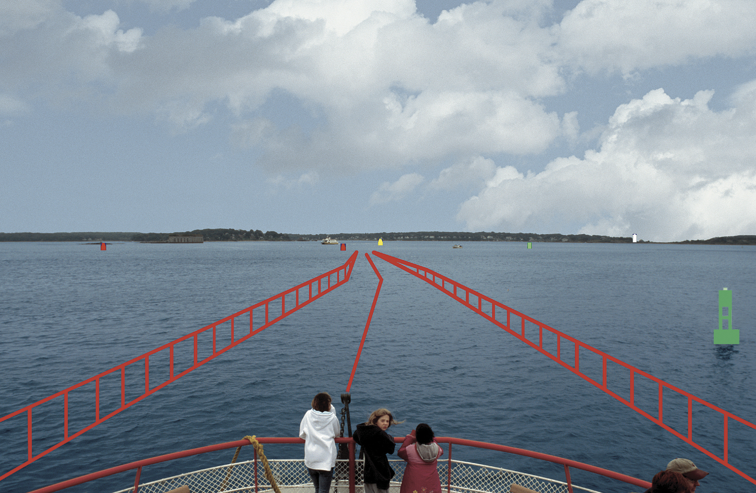
    AR can overlay critical chart information such as buoys and channel markers, as well as radar or automated information system (AIS) contacts. In fact, any information that has a geo-registration component (geographic location attached) can be precisely overlaid on a real-time or infrared camera view. Operators have reported they are able to maneuver in unfamiliar waters at high speed with confidence, especially at night or in inclement weather (Figure 3).

    Photo: Thomas Zysk, Jeffory Luce, and James Cunningham
    Figure 3. Obscure visibility with augmented reality.

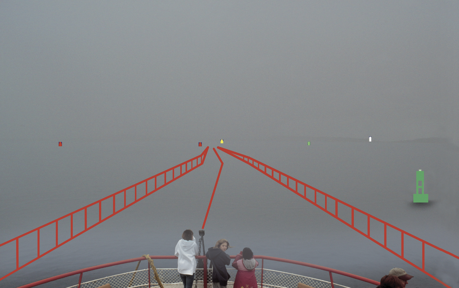
    An operator using AR does not have to look down at a chart, radar, or AIS display, and then up at the real world to put the information into context. Charts, radar, and AIS output 2D information that must be made relevant to a 3D world. Analysis shows that converting 2D to 3D is a strenuous and error-prone task for the brain. Accidents can be caused by an initial mistake, which is then compounded by other decisions made with incorrect information. Figure 4 shows how AR automates the conversion process, allowing the human to focus on other relevant tasks.

    Photo: Thomas Zysk, Jeffory Luce, and James Cunningham
    Figure 4. Augmented Reality Visualization of the Common Operational Picture (ARVCOP) block diagram.

    R & D Hardware

    AR applications on AAVs have demonstrated the technology’s utility on land, in water, and through the hazardous surf zone, delivering precise routing through cleared transit lanes. The system is intuitive to operate. Operators with little or no training in AR systems executed precise maneuvers through lanes planned with bends and turns. The AR system used a military GPS and heading device. Electronic chart and tactical data brought positional context to the display. A virtual world was created and software algorithms draped the virtual world over a real-world camera view creating an AR display (Figure 5) for the AAV test.

    Photo: Thomas Zysk, Jeffory Luce, and James Cunningham
    Figure 5. AAV with research and development commercially available ARVCOP hardware.

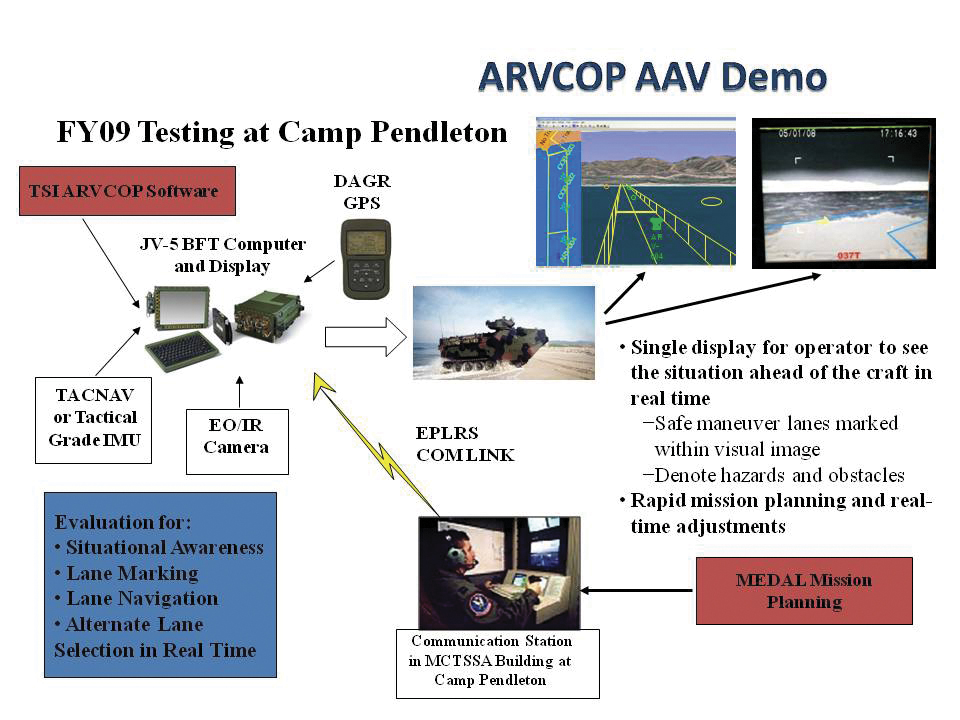
    Camp Pendleton Tests. In 2009, rigorous testing was completed for the ARVCOP system using AAVs in the surf at Marine Corps Base Camp Pendleton. Safe maneuver lanes were marked with mine-like objects and other hazards. Complex routes that included turns and zigzag patterns were planned toward the beach. Routes were delivered to vehicles using a radio circuit, and adjustments to the planned route were made on the fly to adapt to changing tactical situations.

    The AAV is a 26-ton vehicle that is a challenge to operate when placed in a surface environment with wind, waves, and currents. Hardware employed ranged from legacy devices, including a magnetic heading device, to modern devices. With Research and Development (R&D) hardware, the results were dramatic compared to the traditional means of navigating assault lanes. The technology enabled new mission concepts, such as irregular routes ashore and avoidance of hazards sighted by other forces as the mission was in progress. The evaluation criteria for these tests were cross-track errors (CTEs), measured relative to a planned route. Separate, high-accuracy GPS was used for truth data to measure the accuracy of the route driven. Figure 6 shows the video camera and GPS antenna locations on the AAVs.

    Photo: Thomas Zysk, Jeffory Luce, and James Cunningham
    Figure 6. Video camera is located directly beneath the GPS antenna.

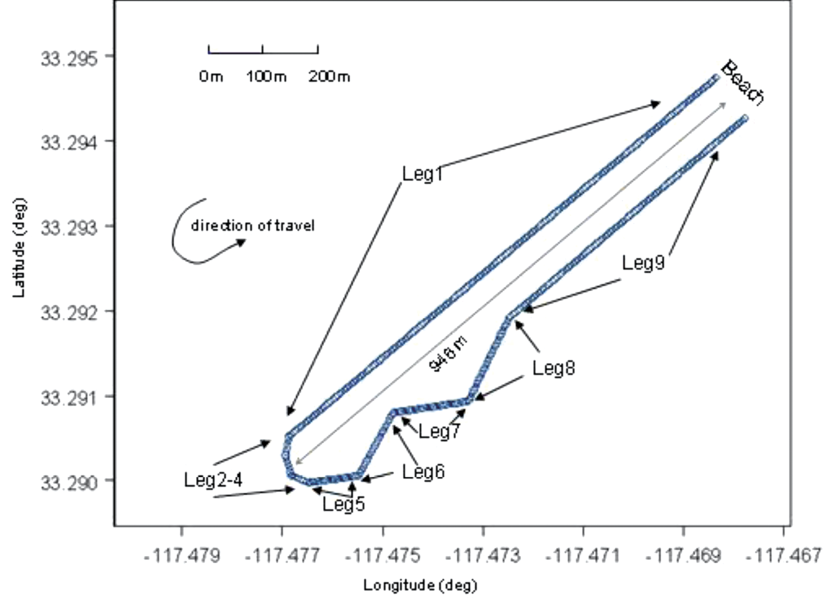
    Figure 7 gives an example of the resultant AR video imagery for the R&D commercially available hardware on the AAVs. Figure 8 shows the planned routes for the R&D test evaluations. The distance offshore was 946 meters, and the planned total route length was 1,990 meters.

    Photo: Thomas Zysk, Jeffory Luce, and James Cunningham
    Figure 7. ARVCOP video using R&D hardware.
    Photo: Thomas Zysk, Jeffory Luce, and James Cunningham
    Figure 8. Planned route for the R&D testing.

    Video Augmentation Accuracy

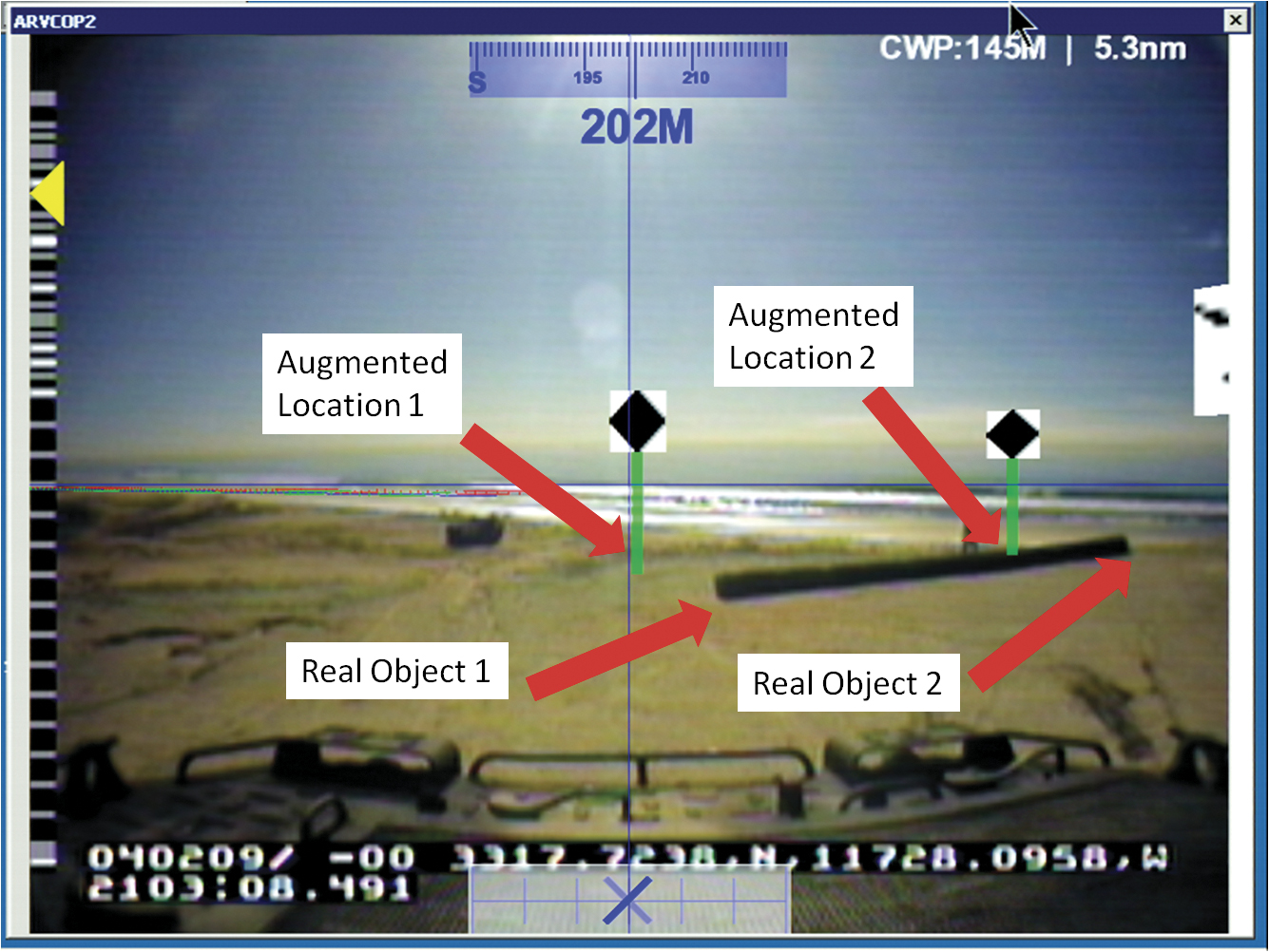
    To determine position accuracy of the augmented figures drawn on the video images, time encoded images were captured. The augmented images were captured by ARVCOP using both the Civilian-Miniature Integrated GPS/INS Tactical System (C-MIGITS III) and the Tactical Navigation Digital Compass System (TACNAV) as input devices. Typically, multiple images are used to determine reference frame biases between the camera and the inertial measurement unit but, in this case, multiple image solutions lacked convergence. For this analysis, single-image solutions were generated. Figure 9, which shows locations of virtual and real objects, is an example of an image used in this analysis. The reference location of the virtual object is the bottom of the green post. The real-object coordinates input to ARVCOP were generated using a GPS survey and have centimeter-level accuracy. Figure 9 illustrates the inaccuracies in the system. During this calibration test, the augmentation showed errors of about 100 mrad (6 degrees) in the display of the virtual objects. (Authors’ note: This paragraph accurately reflects system performance on that day three years ago. Shortly after the test, system modifications were made that eliminated much of that error.)

    Photo: Thomas Zysk, Jeffory Luce, and James Cunningham
    Figure 9. ARVCOP image captured showing virtual and real objects.

    Test Results

    Evaluation of the AAV operation using ARVCOP as a driver’s aid was done by comparing the planned route with the actual route driven. The comparisons were made by finding the distance normal to the route, input to ARVCOP, and the vehicle’s estimated positions, generated using a GPS-relative positioning technique; no vehicle heading information was used and only horizontal components were compared. These differences between planned and executed routes are the CTEs. As mentioned earlier, both the C-MIGITS III and the TACNAV were used as input to ARVCOP for these tests. Figure 10 shows an example of the raw data, with the ARVCOP planned route (blue) overlaid with the GPS estimated positions (red). In this example, ARVCOP used C-MIGITS III heading input updated at a 10-Hz rate.

    Figure 10 illustrates how the AAV stayed on the planned course, showing only small deviations. The blue line represents the planned route and the red points are the GPS-estimated positions.

    Photo: Thomas Zysk, Jeffory Luce, and James Cunningham
    Figure 10. AAV planned and actual route, Run 2.

    When TACNAV was employed to supply heading information, similar results were seen. Figure 11 shows the first run made with TACNAV heading estimates. The AAV stayed on planned route except for some minor deviations.

    Photo: Thomas Zysk, Jeffory Luce, and James Cunningham
    Figure 11. AAV planned and actual route, Run 5.

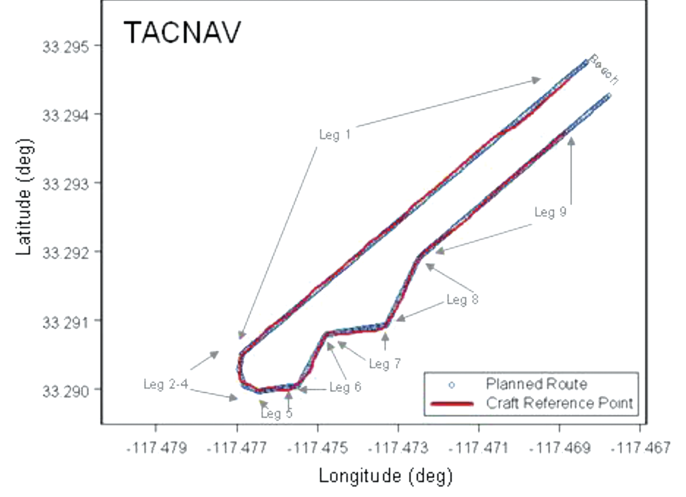
    Figure 12 is of the second run using TACNAV heading information. In this instance, larger and more frequent excursions from the planned route are shown. The differences between Figures 11 and 12 are the result of the driver’s interpretation of the ARVCOP display. When the TACNAV was used as input to ARVCOP, the driver’s display showed greater instability than when the C-MIGITS III was used. The instability was a 1-Hz, few-degree shift in augmentation on the video corresponding to the TACNAV input rate. Figure 12 shows the result of the driver trying to follow all the augmentation shifts. When the driver ignored the sudden shifts in augmentation and drove a perceived average route, the resulting track was smoother, as Figure 11 shows. The 1-Hz input rate and the inherent TACNAV variations both contributed to the augmentation’s jumpy appearance.

    Photo: Thomas Zysk, Jeffory Luce, and James Cunningham
    Figure 12. AAV planned and actual route, Run 6.

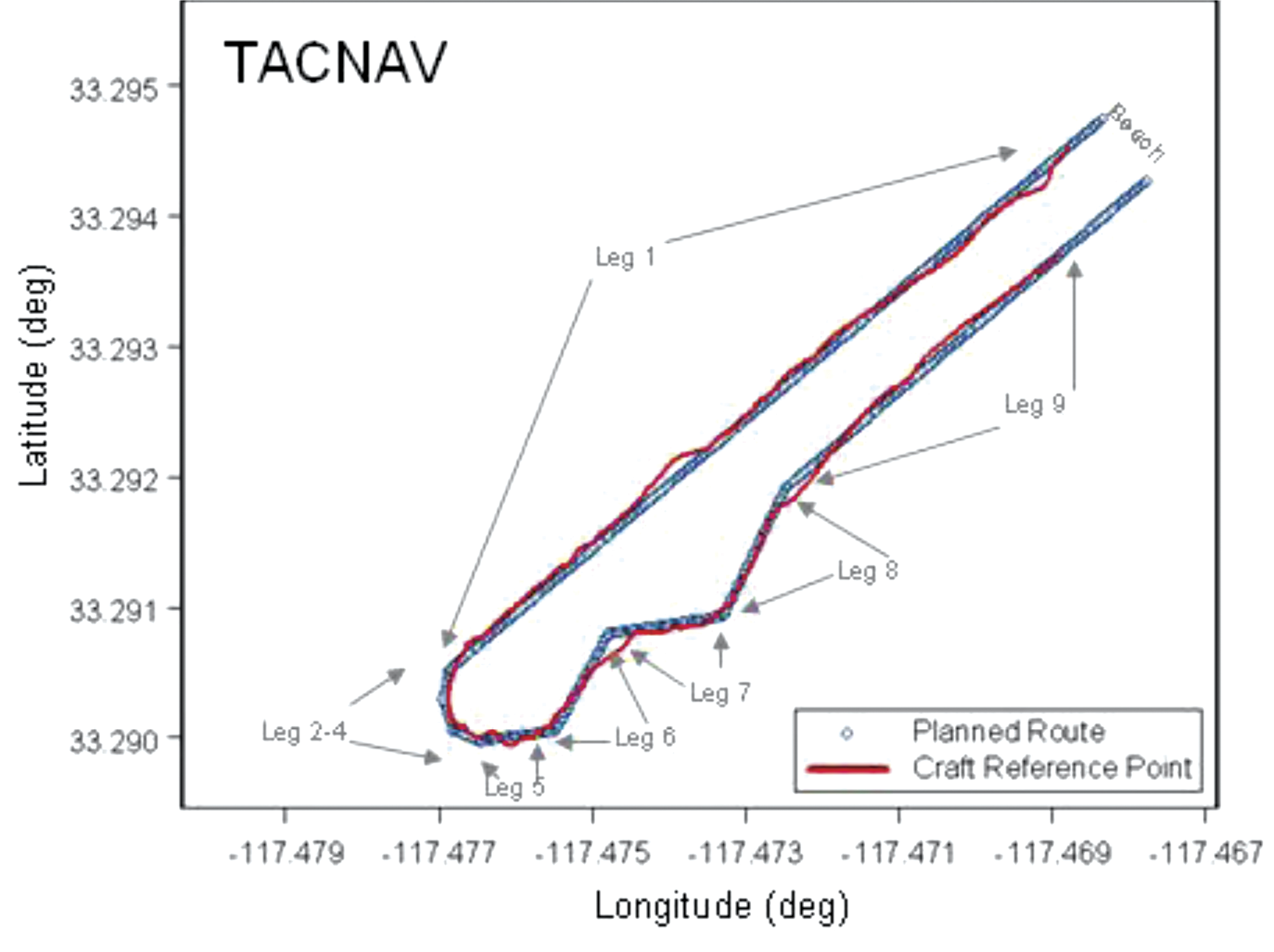
    Figure 13 shows the tracks of all the runs from the February 2009 tests that used the C-MIGITS III, except for runs 7 and 8. Run 7 was excluded because high surf caused its early termination when the vehicle was ordered to shore by the safety officer. The driver’s display was lost during Run 8 because of a loose cable and the test was aborted.

    Photo: Thomas Zysk, Jeffory Luce, and James Cunningham
    Figure 13. AAV planned and actual route, C-MIGITS-III heading data.
    Photo: Thomas Zysk, Jeffory Luce, and James Cunningham
    Table 1 (left) shows the CTE statistics for the C-MIGITS–III runs. Table 2 (right) shows the CTE statistics for the TACNAV runs.

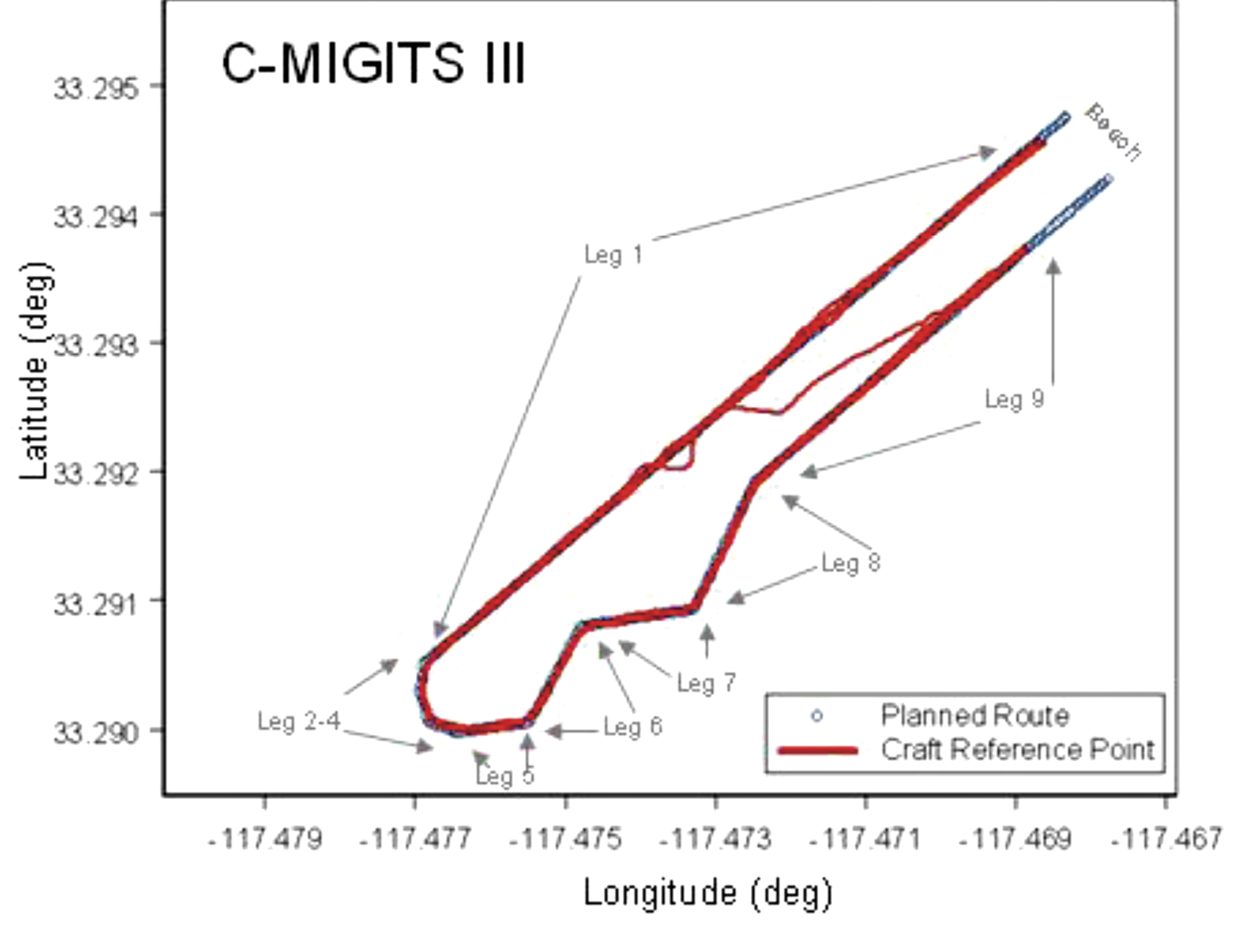
    Table 1 shows the CTE statistics for the C-MIGITS–III runs. Table 2 shows the CTE statistics for the TACNAV runs. Average speed over the course varied from 4 to 5 knots. It took about 15 minutes to drive the entire route.

    Discussion

    Comparison of the heading estimates between the C-MIGITS III and the TACNAV estimates showed variations of about 3 to 5 degrees, after removal of a bias. Investigation of the relationship of the heading angle error with the heading angle showed that after TACNAV calibration, significant heading error correlations remained in its estimates. Using the TACNAV as a source of heading information showed that the slower 1-Hz update rate and inherent variations of the sensor degraded the augmentation software’s performance. For example, when using the TACNAV, the augmented lane boundaries occasionally jumped a few degrees corresponding to the receipt of heading estimate updates. This was particularly evident after vehicle turns. The C-MIGITS III 10-Hz update rate and higher accuracy estimates enabled ARVCOP augmentation without distracting artifacts and provided the driver with more accurate navigation information. The ARVCOP-augmented objects were drawn on the video with a heading accuracy of about 6 degrees.

    During February 2009 R&D tests, the AAV made eight surf runs using ARVCOP with C-MIGITS III input and two runs using TACNAV input. CTE statistics for the ARVCOP C-MIGITS-III testing showed rms differences of about 2.9 meters. The ARVCOP TACNAV testing showed larger rms differences of about 4.9 meters. These statistics represent the rms error between the AAV’s planned and executed route.

    Summary

    AR technology provides a human-machine interface for a navigation system enabling precise maneuvering. ARVCOP presents navigation data so intuitively that operators are able to multitask as required in mission performance while still being able to precisely maneuver. ARVCOP proved the concept of AR-based precise navigation in rigorous operational scenarios with the U.S. Marine Corps (USMC).

    Test results for the R&D commercially available civilian GPS/INS hardware provided CTE of mean 2.1 meters and standard deviation of 2.0 meters. Operational hardware was evaluated in July 2009 over four days of testing, including 47 runs, in conditions with sea states ranging between 1 and 2.5, and many drivers. In 2010, at NSWCDD and Naval Surface Warfare Center, Panama City Division (NSWCPC), land demonstrations were performed with similar hardware navigating cleared paths through simulated mine fields at night. Vehicles were able to transit cleared routes with no external markings. The Naval Sea Systems Command Program Manager, (PMS 495), Mine Warfare Office, is now installing ARVCOP on USMC AAVs.

    Acknowledgments

    This work was sponsored by Brian Almquist, program officer, Ocean Battlespace Sensing Science and Technology Department, Office of Naval Research. LtCol Brian Seiffert, USMC, acting director of the Amphibious Vehicle Test Branch (AVTB), Camp Pendleton, supported the demonstration. GySgt Chapa and SSgt Schaefer, USMC, coordinated the AVTB effort. Kennard Watson, NSWCPC, coordinated the Camp Pendleton test plan. William Chambers, Maritime Technology Consulting LLC, Udayan Bhapkar, Andrew Sutter, and Alan Evans, NSWCDD, supported the tests and evaluations. Ronald Paradis, KVH Industries, Inc., supported heading sensor calibration.

    Manufacturers

    The C-MIGITS III is made by Systron Donner Inertial Division (www.systron.com) and TACNAV by KVH Industries (www.kvh.com).


    Tom Zysk (captain, U.S. Navy, retired) has more than 35 years of experience in the Department of Defense and industry. He held positions with Raytheon and General Dynamics before joining Technology Systems Inc.

    Jeffory Luce is a senior program manager at Technology Systems, Inc. (TSI). As lead for the ARVCOP program, he successfully transitioned TSI’s first project to a Program of Record.

    James Cunningham has worked in GPS research and development at the Naval Surface Warfare Center, Dahlgren Division, for more than 25 years

  • Siberian City Sees Rebirth from GLONASS

    The Siberian city Zheleznogorsk, a hub of Russian space and nuclear technology, fell on hard times in the 1990s. Now, GLONASS has infused a new life and vitality into this once-secret city, as described in a feature by Russia and India Reports.

    The feature discusses the city’s history as attracting young scientists and specialists in the 1950s and 1960s, then its stagnation in the 1990s until its rebirth today, as a hub for GLONASS production. About 40 satellites are in production at the same time, including secret military systems, GLONASS satellites, and telecommunications and geodesy satellites for Russian operators.

    Read more at Glonass Revives Siberian Space Hub.

  • Magellan Truck GPS Navigator Helps Truckers Plan Routes, Drive Safely

    Magellan Truck GPS Navigator Helps Truckers Plan Routes, Drive Safely

    Photo: MagellanMagellan, maker of innovative GPS devices for vehicles, outdoor and mobile navigation, today announced the newest addition to its Magellan RoadMate Commercial GPS family for truckers and commercial drivers providing improved safety and productivity before, during and after their on-the-road trips. The compliance-ready Magellan RoadMate Commercial 9270T-LM GPS device is specifically designed for the needs of truckers including an extra-large GPS display, customizable truck-specific routing, hands-free communication, and trip logging.

    To prepare for their trips, truck drivers can use the Magellan RoadMate Commercial 9270T-LM to set up customizable routes based on the height, weight, width, and length of the vehicle, as well as applicable hazmat restrictions. Multi-destination routing allows drivers to plan their stops and optimize routes to help them save time and gas, Magellan said.

    While on-the-road, the Magellan RoadMate Commercial 9270T-LM helps drivers navigate on an extra-wide 7-inch high-definition touchscreen display that adjusts color and contrast for easy night-viewing. The large display also makes maps and other content easy to read when the GPS Navigator is mounted in large vehicles with deep dashboards. The integrated Bluetooth wireless technology, when paired with a compatible Bluetooth phone, enables drivers to safely talk hands-free while keeping their eyes on the road.

    At the end of their trip, the Magellan RoadMate Commercial 9270T-LM facilitates preparing required compliance reports including hours and state mileage for IFTA fuel records. A comprehensive log of trip information by each driver is retained in the Magellan GPS device for easy exporting into reports.

    “We expanded our family of Magellan RoadMate Commercial GPS Navigators to further meet the unique navigation needs of commercial and truck drivers who need a comprehensive solution to efficiently perform their jobs from the initial trip planning stage to their on-the-road requirements and managing required log reporting after their trip,” said Stig Pedersen, Associate Vice President of Product Management for Magellan. “The Magellan RoadMate Commercial series of GPS Navigators are designed to make drivers’ jobs safer and less stressful plus improve productivity, reduce costs and ultimately increase profits.”

    The Magellan RoadMate Commercial 9270T-LM functions as an “information dashboard” that not only navigates, but provides elevation and truck speed limit warnings. The 9270T-LM GPS device includes several valuable safety and convenience features:

    • Highway Lane Assist that shows realistic highway signs and guides truck drivers towards the correct lane when approaching complex highway interchanges and exits;
    • Free Lifetime Traffic Alerts that help drivers avoid traffic incidents on their route by offering an alternative solution;
    • Spoken Street Name guidance that announces the street name and gives turn-by-turn directions;
    • Highway Exit Points-of-Interest and a Truck Stop Directory help drivers find services including gas stations, restaurants, ATMs, rest areas and showers, truck services, Wi-Fi availability;
    • OneTouch lets truckers bookmark and assign a button to their favorite destinations or searches for faster access;
    • Heavy-duty extended windshield mount, designed for deep dashboards, is included to provide fully-adjustable, personalized comfort and safe viewing;
    • An A/V input for easy connection to external devices such as the Magellan Wireless Back-up Camera or a DVD player;
    • Free downloadable Lifetime Map Updates keep the pre-loaded maps of the United States, Canada and Puerto Rico up-to-date.

    The Magellan RoadMate Commercial GPS family now includes two models — the new 7-inch Magellan RoadMate Commercial 9270T-LM ($399.99 MSRP) and the 5-inch Magellan RoadMate Commercial 5190T ($379.99 MSRP). Both models are available in June at truck stops and through Magellan’s consumer electronics and online partners.

  • Abaqus, 1Shop Wireless Launch myGeoTracking MRM Service for T-Mobile Business Customers

    Abaqus, Inc., developer of device-neutral, cloud-based location and messaging platform that enables high-quality, low-cost mobile workforce and asset management solutions, and 1Shop Wireless, a national business partner sales (BPS) master agent for T-Mobile USA, have teamed to provide the cloud-based myGeoTracking mobile workforce management service for T-Mobile customers.

    “We’re really excited to work with Abaqus to offer their myGeoTracking MRM service to T-Mobile customers,” said Peter Giansante, director of sales for 1Shop Wireless. “It’s an ideal device-neutral location-based-solution for companies that want to equip their employees with feature phones and smartphones, and want to avoid the deployment and training issues associated with mobile apps-based MRM services.”

    The Abaqus myGeoTracking platform provides a unique cloud-hosted solution that combines network-derived and phone-based GPS location information with fine-grained privacy control options, location-enhanced SMS, and a powerful rules engine to let companies quickly and easily manage their field-personnel and assets. It does not require special devices & smartphones, expensive data plans, cumbersome applications, or software.

    “Abaqus’ myGeoTracking bizTeam service is a great fit for any field-force oriented T-Mobile customer that needs to deploy a mobile management solution,” said Gillian Foley, vice president of One Shop Wireless.

    Unlike smartphone-based applications that require special phones and client applications, the location-enhanced, SMS-based myGeoTracking mobile workforce management solution from Abaqus can locate any phone on a cellular network using either Cell ID information, or a precise location using GPS inside the device. The platform provides fine-grained controls to the dispatcher or the employee in the field to pull or push location data using simple SMS commands. The myGeoTracking platform has a rich web API which can be used to integrate with a range of back-office Enterprise systems, Abaqus said. The service provides SMS-based messaging for team job status reports, and has a powerful rules engine that can use geo-fencing, time, device identity, workgroup and other terms to integrate into a company’s mobile workflow needs on a day-to-day basis.

    • The myGeoTracking bizTeam service is an MRM solution which is completely cloud-based and does not require special GPS devices, special phones or any new software.
    • The myGeoTracking bizTeam MRM service can use any standard feature phone to send location and event information, and complies with USPS location standards.
    • The myGeoTracking bizTeam MRM service provides fine-grained privacy controls which can be managed by the end-user from their mobile phones or from the web site
    • Location-enhanced SMS (myGeoText ™) lets your mobile workers actively send you a date, time and location stamped status message from the field and trigger additional dispatch functions.
    • The myGeoTracking bizTeam MRM service provides Geofencing, Geo-corridors, and a variety of other events-based rules to enable easy integration of real-world alerts into a company’s workflow
    • The myGeoTracking bizTeam service provides rich reporting tools which can be exported to a company’s backoffice systems
    • The myGeoTracking MRM bizTeam service provides an Enterprise SMS feature which lets customer’s enhance their dispatch and operations by messaging individuals, groups, or the whole company.
    • The myGeoTracking Platform Integrates with a range of back-office programs through a rich web API.
  • Digital Matter Embedded Introduces GPS Log Book Based on u-blox Technology

    Digital Matter Embedded Introduces GPS Log Book Based on u-blox Technology

    Photo: Digital Matter Embedded

    Digital Matter Embedded, a South African based provider of innovative technology providing electronic and software solutions for a wide range of Industry applications, has launched a compact GPS logging device which plugs into any vehicle’s cigarette lighter. The device, the GPS Log Book, is designed around u-blox’ NEO GPS receiver module to provide an easy way for drivers to automatically keep an accurate travel log book which can be securely accessed later from anywhere via a web interface. Information logged includes route, speed, and distance traveled. The device is targeted at businesses where tracking of vehicle usage is an important part of their cost control and accounting: taxi, emergency, and delivery services, as well as for traveling sales personnel.

    “The GPS Log Book takes advantage of u-blox’ extremely sensitive GPS receiver technology to provide a simple and useful way to keep an accurate overview of vehicle usage,” said Alex Soldatos, general manager at Digital Matter Embedded. “The GPS Logbook provides a simple, cost-effective way for businesses to keep track of one of their most valuable assets: their cars.”

    “The GPS Log Book takes full advantage of u-blox’ leading positioning technology: it requires fast satellite acquisition and re-acquisition speeds, small module size, and high sensitivity to allow the use of a very small GPS antenna,“ said Huub Robroek, regional sales manager at u-blox. “Basing their design on our NEO GPS module has resulted in an impressive, compact device that delivers useful and reliable vehicle usage data.”

    The GPS Log Book uploads its log data on both PC or Mac via USB where a web interface application allows users to manage their devices, view trips, and add locations as well as many other useful functions including creating powerful, informative reports. Most notably, the log book can be generated for use with income tax return for individuals. Data is stored for more than five years and can be viewed at any time if required.

  • GSA Releases 2012 SatNav Market Report

    The European GNSS Agency (GSA) has published its second Global Satellite Navigation System (GNSS) Market Report, providing key information to entrepreneurs in the satellite navigation sector.

    GNSS market forecasting is of great interest to private and public GNSS stakeholders, for business and strategic planning and policymaking, according to the GSA. According to the 2012 GSA Market Monitoring Report, the worldwide GNSS market is growing fast and the total market size is expected to increase at an average of 13 percent per year until 2016.

    The total enabled GNSS market size is expected to stabilise in the latter half of the decade due to market saturation, price erosion and platform convergence. Global shipments of GNSS devices are lower than previously forecasted up until 2015 yet are forecasted to continue growing to over 1.1 billion units per year.

    Expanding coverage. Following up on the first GNSS Market Report published in 2010, the GSA’s 2012 Report includes an analysis of two new sectors: maritime and surveying. Relevant examples from EU research projects have also been included for each sector.

    2012 Report Highlights

    Road and location-based services (LBS) still in the lead. Road and LBS dominate GNSS device sales (54% and 44% respectively). LBS constitutes 87% of the total GNSS market in terms of units sold and GNSS penetration in smartphones is set to increase from 30% today to almost 100% in 2020. For road navigation, traditional Personal Navigation Devices (PNDs) will gradually disappear from the European market yet remain present in other regions in the form of low cost OEM products. Smartphones and in-vehicle devices will be the preferred means of navigation.

    Commercial aviation use will grow. In the Aviation sector, the segment that will see the greatest growth in terms of GNSS equipment revenues will be Commercial Aviation, surpassing general and business aviation by 2018.

    GNSS use in agriculture continues to rise. In agriculture the current positive growth trend will continue; low cost precision agriculture solutions based on EGNOS are driving GNSS adoption by farmers in Europe.

    Surveying: a growing opportunity. In surveying, the construction segment is dominating the market in terms of units and value. North America is leading in terms of market penetration but the other regions will catch up by 2020 as GNSS is rapidly replacing the traditional surveying and mapping methods in Europe and around the world.

    Safer seas with GNSS. In the open sea segment, shipments of search-and-rescue (SAR) beacons will exceed those of other categories making the SAR segment the largest in terms of shipments and second largest in terms of market size.

    The 2012 GSA Market Monitoring Report can be downloaded for free.

  • NovAtel, L-3 Interstate Electronics Partner on Civil RTK and SAASM Receiver Card

    NovAtel Inc. today announced the development of its OEM625S Selective Availability Anti-Spoofing Module (SAASM) GNSS receiver, a collaborative effort between NovAtel and L-3 Interstate Electronics Corporation (IEC).

    System integrators have come to rely on the centimeter-level positioning accuracy made possible with real-time kinematic (RTK) commercial GPS receivers. Many authorized defense customers rely on access to the Precise Positioning Service (PPS) for single-point positioning. The OEM625S will combine a commercial dual-frequency NovAtel GNSS receiver with an L-3 IEC XFACTOR SAASM in a single card solution, reducing overall size and power requirements for end customer applications.

    The OEM625S will maintain NovAtel’s OEMV-2 form factor, ensuring a successful drop-in replacement and backward compatibility for existing customers. Integrators can continue to use their existing user interface, which will be enhanced with OEM625S logs and commands for SAASM functionality.

    NovAtel’s well-established, comprehensive set of software commands facilitates system integration, NovAtel said. The SAASM position is provided via a dedicated communication port, as well as through NovAtel’s software command protocol, allowing for maximum flexibility.

    “For the past 17 years NovAtel’s customers have enjoyed great success in integrating our OEM family of high-precision receivers into a wide array of defense applications,” stated Graham Purves, executive vice president of NovAtel. “Adding the L-3 XFACTOR SAASM to our receiver card will allow defense customers to continue to use our products in the most demanding military environments.”

    Ric Pozo, general manager of L-3 IEC’s Navigation Systems business unit, commented, “We are pleased to collaborate with NovAtel and provide the warfighter this highly flexible and capable GPS SAASM product. Our combined teams are looking forward to bringing this one-of-a-kind solution to market.”

    NovAtel will accept orders for the OEM625S from authorized customers starting in the third quarter of 2012.

  • OpenGeo Suite 2.5 Released

    OpenGeo released version 2.5 of their flagship product, the OpenGeo Suite. Version 2.5 bundles many improvements and bug fixes from the open source communities and adds special OpenGeo features, including a toolkit for developing and deploying applications powered by the OpenGeo Suite, and improved raster format support. OpenGeo, an innovator who introduced unlimited support on a complete open source mapping stack, continues to innovate with the 2.5 release. The fully integrated suite takes the pain out of installing and upgrading open source components. Stand-alone, production-ready downloads make it simple for users to install and upgrade scalable, multi-tier deployments of the OpenGeo Suite.

    According to the announcement, the highlight of version 2.5 is the the introduction of the OpenGeo Suite Client SDK. The much anticipated SDK provides tools for developing and deploying web mapping applications backed by the OpenGeo Suite. By providing a plugin-based architecture and leveraging OpenLayers, Ext JS, andGeoExt the SDK allows users to build powerful web mapping applications by providing a JSON configuration.

    When reached for comment about the SDK Tim Schuab, OpenGeo CTO said “The Client SDK provides a robust toolkit for rapidly creating, debugging, and deploying browser based mapping apps. We’re excited to include the initial version of the SDK in the 2.5 release and will continue building on it, focusing on customizing server side functionality and developing mobile applications.”

    The 2.5 release also comes with support for publishing data from formats supported by the Geospatial Data Abstraction Library (GDAL), including: DTED, EHdr, AIG, ENVIHdr, and more. MrSID is available to those with a license for LizardTech’s decoding software development kit. Other noteworthy changes include:

    • Improvements to the GeoServer Layer Importer, including Oracle and SQL Server options and support for importing ZIP files containing multiple Shapefiles.
    • Options in GeoServer to allow layers to be available but not advertised as well as options for producing lenient capabilities documents to prevent invalid XML output from misconfigured layers.
    • Better WFS output from GeoServer, including paging and sorting in the WFS capabilities and user-defined WFS GetFeatureInfo output.
    • Better 3D support in GeoServer and GeoTools, including proper handling of read/write of 3D polygons from Oracle and proper handling of 3D data in GML3 encoding.

    More specific information is available in the release notes. OpenGeo Suite 2.5 is available for download free of charge with a 30 day trial of OpenGeo’s enterprise support.

  • Lockheed Martin Completes Navigation Payload Milestone for GPS III Prototype

    The Lockheed Martin team developing the next generation Global Positioning System III satellites has completed a major integration and test event on the program’s satellite pathfinder, known as the GPS III Non-Flight Satellite Testbed (GNST). The milestone is a key indication that the GPS III team is on track to deliver the first satellite for launch availability in 2014.

    In Lockheed Martin’s new GPS Processing Facility (GPF), engineers successfully powered on the GNST with major elements of its navigation payload to include advanced atomic clocks for improved GPS accuracy, and the mission data unit, the heart of the GPS III navigation payload. The test was completed in advance of integrating the full navigation payload element, which is scheduled for delivery to the GPF this fall.

    The GPS III program will replace aging GPS satellites while improving capability to meet the evolving demands of military, commercial and civilian users worldwide. GPS III satellites are expected to deliver better accuracy and improved anti-jamming power, while enhancing the spacecraft’s design life and adding a new civil signal designed to be interoperable with international global navigation satellite systems.

    Incorporating lessons learned from previous GPS programs, the Air Force initiated a “back-to-basics” acquisition approach for GPS III. The strategy emphasizes early investments in rigorous systems engineering and industry-leading parts standards to significantly reduce risk, improve production predictability, increase mission assurance and lower overall program costs. These investments early in the GPS III program are designed to prevent the types of engineering issues discovered on other programs late in the manufacturing process or even on orbit.

    “The GNST is the cornerstone of the Air Force’s back-to-basics acquisition approach, and this milestone demonstrates that GPS III is on track and the acquisition strategy is working,” said Keoki Jackson, vice president of Lockheed Martin’s Navigation Systems mission area. “The Air Force’s early investment in meticulous parts standards and rigorous systems engineering will significantly reduce per unit production costs and ensure mission success.”

    As production progresses on the first GPS III satellite, the team has already benefited from lessons learned on the GNST. Early efficiencies identified include:

    • 50-80 percent reductions in labor hours and defect rates between similar activities on the GNST and the first space vehicle.
    • Identification of tens of millions of dollars in cost savings for the production satellites based on process improvements recognized during GNST integration and test.

    “As we continue learning lessons on the GNST and move into full scale satellite production, we expect to continually streamline our processes and reduce per unit costs,” Jackson said.

    In 2008, Lockheed Martin was awarded the contract for the design, development, and production of the GPS III Non-Flight Satellite Testbed (GNST) and the first two GPS III satellites, with priced options for up to 10 additional satellites. In early 2012, the Air Force exercised a $238 million option for production of the next two satellites, GPS III space vehicles three and four. The Air Force plans to purchase up to 32 GPS III satellites.

    The GPS III team is led by the Global Positioning Systems Directorate at the U.S. Air Force Space and Missile Systems Center. Lockheed Martin is the GPS III prime contractor with teammates ITT Exelis, General Dynamics, Infinity Systems Engineering, Honeywell, ATK and other subcontractors. Air Force Space Command’s 2nd Space Operations Squadron (2SOPS), based at Schriever Air Force Base, Colo., manages and operates the GPS constellation for both civil and military users.

  • Gakstatter to Give GNSS Technology Update at Esri Conference

    Eric Gakstatter, GPS World’s contributing editor for Survey/GIS, will speak at the 2012 Esri International User Conference, which will be held July 23-27 in San Diego, California.

    In his “GPS/GNSS Technology Update,” Gakstatter will provide a discussion on how current and upcoming satellite systems affect the user. The talk will be held in Room 31B at 10:15-11:30 a.m. on Thursday, July 26. Here is the official description:

    ArcGIS Mobile users around the world are challenged to keep current with evolving satellite systems. There are new GPS satellites being launched with new GPS signals being broadcast (L5). The Russian GLONASS system is near operational and Europe has launched its first two Galileo satellites. Not only are the satellite systems changing but also GPS augmentation systems such as WAAS, DGPS, EGNOS, MSAS and GAGAN systems. ArcGIS Mobile users take advantage of these GPS/GNSS augmentation systems and should be aware of how they are evolving. The LightSquared controversy is still a major threat to GPS/GNSS users. How might that affect the future of GPS/GNSS mapping/surveying? How do these changes affect spatial data collection and navigation services within ArcGIS Mobile? Which factors should one consider when using these different satellite systems. What are the current trends and developments that one should consider when preparing GPS/GNSS mapping hardware budgets?

    To learn more about the conference, read about it in our Events section here.

  • Spirent Launches Entry-Level Multi-GNSS Simulator

    Spirent Launches Entry-Level Multi-GNSS Simulator

    Photo: Spirent Communications

    Spirent Communications today announced the launch of its new GSS6300M Multi-GNSS simulator designed for integration, verification, and production testing where a quick and accurate functional test is needed. The platform supports simulation of signals from individual or combined GPS/SBAS, GLONASS, and Galileo constellations, with eight satellites per constellation.

    The GSS6300M supports two modes of operation — integrated into an Automated Test Equipment (ATE) environment or using Spirent’s SimCHAN software. For automated operation, the GSS6300M can be synchronized with other equipment and controlled remotely over Ethernet, IEEE-488 (GPIB), or RS232 interfaces. The SimCHAN software interface supplied with the GSS6300M enables the user to create unlimited scenarios and specify parameters such as user position, date, and time. Both modes support precise user control over power level and atmospheric effect selection.

    “The GSS6300M is designed for customers who want an affordable, easy-to-use multi-GNSS test system with the quality, reliability and support that is expected from Spirent,” said Rahul Gupta, product manager with Spirent’s Positioning Technology business. “The GSS6300M enables testing of fundamental receiver functionality including time to first fix, sensitivity, and accuracy.”

    The GSS6300M is now available for order. A field upgrade pack is available for existing Spirent GSS6300 customers who want to leverage the multi-channel capabilities of the GSS6300M.