I started my relationship with GNSS and Moore’s Law in 1985, writing software for GPS tracking loops on the Advanced Range Instrumentation Aircraft program at the Applied Physics Laboratory of Johns Hopkins University for the U.S. Air Force. The project’s purpose was to navigate a large jet to accurately fly a pattern to drop buoys into the ocean. That receiver had seven circuit boards (six trackers and one navigator) mounted on a VME backplane in a 19-inch rack mount in the back of a C-130, and was about the size and weight of suitcase.
In 1988, I helped design and build a single-board Swordfish receiver at Stanford Telecom that went into a two-man portable pseudolite for Trident missile testing. This was considerably smaller and lighter: about the size and weight of a desktop computer. Moore’s law — which, by the way, states that the number of transistors that can be placed inexpensively on an integrated circuit doubles approximately every two years — helped mostly by allowing much better CPUs and memories so we could put it all on a single board. I actually carried this beast off a landing ship tank (LST) onto a small island in the South Pacific called Kwajalein.
With Moore’s law in full swing in 1990, I moved to the commercial sector at Trimble Navigation and worked on the NavTrac, a lunchbox-sized complete GPS receiver for marine navigation, and then onward to timing receivers and eventually credit-card-sized modules. It became clear that Moore’s Law was a great friend of GNSS and was going to enable a whole new slew of applications by moving from the board level to the chip level.
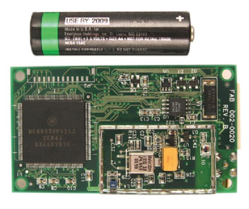
I went to SiRF Technology, Inc., very soon after it was founded in 1995, to help develop the first commercially successful GPS chipset, the SiRFstarI (see photo).
Photo: SiRF Technology, Inc.Photo: SiRF Technology, Inc.
SiRFstarI-based module, both sides, with representative AA battery to scale.
You can see that this module still had separate chips for the CPU, flash, SRAM, GPS correlator chip, the GPS RF ASIC, and a lot of other components.
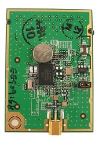
Last year, we introduced the SiRFStarIV architecture and the GSP4e chip. The module made from this chip has the same basic functionality (RF in, position out) but at a much higher performance level in terms of sensitivity, time to first fix, accuracy, and much lower power consumption. The photo at right shows a 4e module. Also note how few external components are required.
SiRF 4e module. A hearing-aid battery shows scale and represents the relative power requirements of this module. Photo: SiRF Technology, Inc.
To really understand the impact of Moore’s law on GNSS today, we have to break down the impact on the various parts of the receiver. The measurement of each section (area, power, or bytes) was then normalized to a starting point of 100 in 1995. The time span of 14 years is about seven Moore’s law doublings (every 2 years), producing an expected decrease of 1/128. We can see that the power and digital silicon area have tracked very well over that time period. However, it is also apparent that RF has not even come down by half in that time frame (although it has swallowed a lot of external components as seen in the pictures) — and the code size (ROM + RAM) has grown by 2.5 times.
This has turned Moore’s law into a bit of a foe in the current timeframe, as the costs associated with silicon products are clearly known to customers (die size is easy to measure) and has driven the prices for GPS receiver downwards accordingly. However, as one can see, more and more software is needed to enable the new features and functions, and with dropping prices due to decreased silicon size, it becomes harder and harder to pay to feed all the hungry engineers here at CSR. This is the crossroad at which our segment of the industry has arrived: how do we continue to add innovation and still make a profit selling silicon when Moore’s Law is not helping anymore? I am not sure I know the answer yet, but we have a lot of good ideas that we are working on.
Most of these ideas come from expanding the notion of location determination to extend beyond using just GPS and its currently available augmentations. Adding support for other GNSS constellations requires more hardware; the amount is highly dependent on which constellation(s) we are talking about. GLONASS, because of its different frequency, requires more RF silicon, requiring more total area because the existing area is not shrinking as fast. Galileo and COMPASS will require more digital area for their complex coding schemes, but these can be more easily handled with shrinking process geometry. All will require significant software effort to bring in new acquisition schemes, tracking loops, and navigation algorithms.
But location determination will not be a GNSS-only problem for much longer. Hybrid navigation using other signals of opportunity and MEMS sensors will play a large role in expanding the ability to provide accurate location to consumers wherever they go. The integration of these technologies into a coherent location determination system is a large software effort, and one that CSR has been working on for years in automotive applications.
Clearly, the need for accurate location continues to grow in consumer devices. At CSR we feel we are in the best position to deliver that, with or without help from Moore’s law.
Greg Turetzky is senior marketing director for SiRF Technology Inc., a member of the CSR Group of companies.
A virtual reference station network covering a metropolitan area supplies position corrections to commuter buses equipped with a driver-assist system to enable safe operation, even under harsh weather conditions, along high-volume roadways.
By Craig Shankwitz
Bus-only shoulders on major traffic arteries enable a bus to travel on typically unused road right-of-way, bypassing congestion during peak rush hours. As the shoulder is typically only centimeters wider than the bus itself, lane-keeping becomes a key factor, and is accomplished in a pilot Minnesota project using dual-frequency, carrier-phase differential GPS (DGPS) as its primary positioning technology. DGPS provides position estimates accurate to 5–8 centimeters at a rate of 10 Hz, and is used to determine vehicle position and heading. An on-board map database is used to determine the position, orientation, and trajectory of the vehicle relative to the roadway.
Use of the shoulder as a busway offers several construction and operational advantages:
Ease of Implementation. The shoulder exists; there is no need to acquire and develop additional right of way.
Low Costs. The cost to strengthen and modify an existing road shoulder is significantly less than constructing a new busway.
Routing. Because bus-only shoulders follow existing routes, no changes to bus routes, bus stops, or transit stations are needed to support bus-only shoulder operations.
Customer Satisfaction. Transit customers who travel on buses that use a bus-only shoulder perceive a travel-time saving two to three times greater than actually realized. Keeping the bus moving at all times offers a significant psychological advantage.
Increased Ridership. A 1997 study of bus-only shoulders in the Twin Cities analyzed more than nine bus-only shoulder routes for two years and found a 9.2-percent increase in ridership along these routes. At the same time, total ridership had decreased by 6.5 percent.
However, the use of bus-only shoulders imposes additional stress and strain on a driver. The narrow bus-only shoulder leaves a driver very little margin of error. Operating within this small margin is difficult even during the best traffic and weather conditions, and degrades to nearly impossible during heavy traffic and poor weather conditions, which are frequent during Minnesota’s notoriously hard winters.
During difficult weather and traffic conditions, the use of the bus-only shoulder offers its greatest transit advantage. If a driver is unable to utilize the bus-only shoulder, this advantage is lost. A properly designed and executed driver-assist system (DAS) enables a driver to use the shoulder under all conditions, thereby increasing schedule adherence and, as a result, rider satisfaction.
Under the U.S. Department of Transportation’s Urban Partnership Agreement, the University of Minnesota’s Intelligent Vehicles Lab (IV Lab) and HumanFIRST program, the Minnesota Valley Transit Authority (MVTA), and Schmitty and Sons Transportation will soon deploy DAS on 10 Gillig low-floor transit buses. These buses will provide express service between Apple Valley and downtown Minneapolis, a 22-mile, one-way trip.
Driver-Assist History
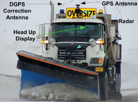
The IV Lab has developed and deployed DGPS-based DAS since 1995. The first deployment on public roads occurred in 2001, as part of the DOT’s Intelligent Vehicle Initiative Generation Zero Field Operational Test. The DGPS-based lane-keeping assistance was integrated with forward-looking radar for collision avoidance, enabling safe vehicle operation in zero-visibility conditions.
Two separate deployments took place in Alaska. The first occurred in 2003 with a snowplow and a snowblower which clear the Thompson Pass on the Richardson Highway. These vehicles are still in use. Because of this success, the State of Alaska installed the DAS in two more vehicles at Deadhorse Airport.
During the summer of 2010, the two original Thompson Pass systems will be upgraded with new computational hardware, and three new systems will be installed on three new highway maintenance vehicles. The value of the driver-assist system has been proven, and those who use it have grown to rely on its all-weather capabilities. It has functioned reliably for seven years in extremely harsh conditions.
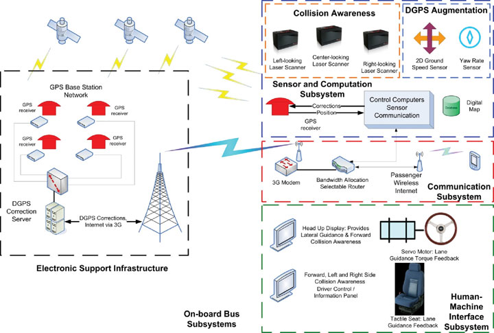
The DAS provides two primary capabilities for transit applications: lane-keeping and collision awareness. The system provides assistance only; a driver is always responsible for control of the vehicle. Figure 1 shows the components comprising the DAS.
Figure 1. Complete driver assist system component schematic, showing both infrastructure-based and vehicle-based components.
DGPS-Based Lane-Keeping. The primary positioning sensor used aboard the buses is a dual-frequency, carrier-phase GNSS receiver, providing centimeter-accurate position measurements at 10 Hz. With the exception of the DGPS augmentation system described later, all other DAS system processes are synchronized with the arrival of DGPS position updates.
Realtime CMR+ DGPS corrections are provided over the 3G cellular network from the IV Lab VRS network. The IV Lab VRS network is based on six receivers located around the perimeter of the Twin Cities Metro area. These six receivers are connected via landlines to a server system located in the IV Lab at the University of Minnesota, running GPSnet and RTKnet applications. To ensure GPS correction reliability, an integrity manager software issues alerts for both short-term and long-term aberrations in the data provided by the six base stations. This ensures accurate corrections are sent to the buses using the narrow shoulders.
The onboard receiver also plays a crucial role in accurately estimating vehicle body heading. In rural applications where GPS augmentation is unnecessary, GPS velocity heading estimates provided directly from a GPS receiver serve as a sufficiently accurate body-heading estimate. However, in GPS-denied environments where an augmentation system is needed to provide accurate position and heading estimates when GPS is lost, velocity heading from an onboard receiver is an insufficiently accurate estimate of vehicle heading. To support such navigation, the IV Lab developed a technique, described later, by which body heading can be estimated with errors less than 0.1 degree.
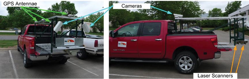
IV Lab mapping rig installed in a pickup truck: three dual-frequency, carrier-phase DGPS receivers; two laser scanners, one measuring retroreflectivity, the other road crown and rutting; and forward and sideview cameras, to help analyze anomalous data.
Map Databases
Lane-keeping uses DGPS with an onboard map database describing the location and type of lane boundaries and other relevant roadway elements to an accuracy of approximately 10 centimeters. These map databases can be constructed in one of three ways:
from sufficiently accurate photogrammetric data,
by driving centerlines and using known road-construction standards to d
etermine the location of lane boundaries and other relevant elements relative to the lane centerline, or
by using a combination of laser scanners, DGPS receivers, and cameras to determine the global location of the reflective markings that bound lanes and shoulders.
Lane-keeping information is continuously provided to the driver; lane-departure alerts and warnings use a comparison of vehicle speed and heading to the map database to determine when alerts and warnings should be issued.
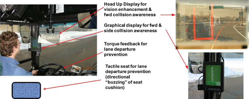
The alerts and warnings are provided via a multi-modal human-machine interface (HMI), illustrated in Figure 2, through three modes:
graphically, through a head-up display (HUD) that gives a virtual view out the windshield when environmental conditions limit visibility;
haptically, through a torque-actuated steering wheel giving a restorative torque on the steering wheel in the event of lane drift; and
tactically, through a seat equipped with actuators that vibrate on the side of the seat to which the lane is being departed.
Figure 2. Multi-modal driver interfaces. Left: Graphical, haptic, and tactile feedback modes provided to the driver. Upper right: View through the head-up display. Graphical lane departure alert indicated by left shoulder boundary colored red, collision awareness alert (white rectangles), and collision awareness warning (red rectangle). Lower right: Forward, left, and right side collision awareness information presented on the display on the left “A” pillar.
Lane-departure warnings come in stages. As the vehicle-trajectory estimator determines that the likelihood of a lane departure is sufficiently high, a lane-departure warning is issued to the driver through the HUD: a change in lane boundary color from white or yellow to red. Should the driver contact the lane boundary, a seat-based warning is activated; the side of the seat corresponding to the direction of lane departure vibrates, warning the driver. If the driver fails to respond to these two stimuli and continues past the lane boundary, the steering motor torque is applied. This multi-stage approach captures the drivers’ attention, but if they respond in a timely fashion, their annoyance is limited.
The torque applied by the steering servo motor is limited, and cannot deliver sufficient control action to autonomously steer the vehicle. This is by design; the driver is responsible for operating the bus. The level of torque applied to the steering wheel is analogous to an automotive front-end misalignment; it is sufficient to capture the drivers’ attention, but not to steer a bus off the road.
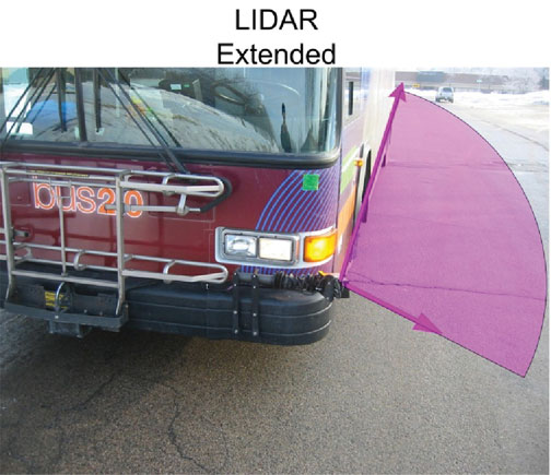
Forward-Collision Awareness. Sensing for forward-collision assistance is provided by a front bumper-mounted multi-plane scanning LIDAR sensor. Forward-collision alert and warning information is provided in two stages to the driver through the HUD. As now configured, if the obstacle detected is in the present shoulder of travel, the obstacle is represented as a red, open rectangle, with red indicating a warning status. If an object is located in an adjacent lane, the obstacle is represented as a white, open rectangle, with white indicating an alert status.
Obstacle-detection processing is enhanced by the presence of the onboard map database used for lane-keeping. Obstacle target information provided by the LIDAR sensor includes range, range rate, and azimuth angle to the target. The bus position and heading is provided by either DGPS or the DGPS augmentation system. Through a coordinate transformation, LIDAR information in the vehicle coordinate frame is transferred to the global coordinate frame. This allows the LIDAR target to be placed on the map database; if the target is in the vehicle lane of travel, it can be considered a threat, but if the LIDAR target is not in the same lane as the bus, then at that time the target is not a threat to the driver.
Side-Collision Awareness. Side collision awareness is enhanced by multi-plane LIDAR scanners mounted on on the front bumpers on both the left and right sides of the bus, and connected to a pneumatic actuator.
Side-collision awareness information is provided to the driver via an LCD panel mounted on the left front A-Pillar (see Figure 2). This display is touch-sensitive, and can be used by the driver to log in (only certified, trained drivers can operate the system) to select feedback modalities (choose any or all of the available feedback modes) and to check system status.
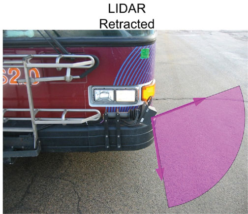
SIDE-MOUNTED LASER SCANNER used for both side-collision awareness and DGPS augmentation. When extended, the LIDAR scans 100 degrees of the horizontal plane. One boundary of the scanned plane points behind and runs alongside the bus; the other boundary points forward of the bus by approximately 10 degrees.SIDE-MOUNTED LASER SCANNER used for both side-collision awareness and DGPS augmentation. When retracted (right), the LIDAR points in the direction of the ground, and can be used for curb-following when DGPS is unavailable.
Suburban and Urban
Although the rural implementation of the DAS operates in extremely harsh weather conditions, these implementations are technically less problematic than suburban and urban implementations. In rural applications such as the snowplows, DAS-equipped vehicles typically operate with a single occupant in a small geographic area, travel on relatively low traffic-volume roads, and enjoy a clear view of the sky. Suburban and urban applications carry passengers, operate across a wider geographic area, travel on high-volume roads, and suffer from periods where view of GPS satellites is either partially or completely blocked.
These operational differences require substantial changes to the DAS subsystems for urban/suburban use.
DGPS Base Stations. In rural areas, DAS-equipped vehicles typically operate over a relatively small geographic area; a single GPS base station will provide adequate coverage as the maximum baseline between rover and the base station remains less than 25 miles. Suburban applications cover a much wider area, and a network of DGPS correction stations is needed to keep baselines low.
For the UPA project, the IV Lab operates a six-station virtual reference station (VRS) network. This network covers the greater Twin Cities Metropolitan area, and supplies compact measurement record (CMR) corrections to each DAS-equipped bus. Satellite observables are sent from each base station receiver to both the VRS server at the IV Lab and to a VRS server at the Minnesota Department of Transportation.
Broadcast of DGPS Corrections. In rural areas, the DAS system has served to keep roads passable in inclement weather conditions. This has been viewed as a safety application, and as such either UHF or VHF channels in the public safety bands have been used to broadcast DGPS corrections. In urban areas, no single UHF or VHF frequency is available to cover an entire metropolitan area. Therefore 3G cellular data communications are used to provide DGPS corrections to DAS-equipped vehicles.
Use of 3G cellular data communications brings the transit customer an added benefit: free Wi-Fi. The provision of DGPS corrections, using the CMR+ correction format, requires approximately 10 Kbit/second. This bandwidth is assigned high priority by the onboard router. The remaining 700 Kbit/s of 3G bandwidth is made available, at a lower priority, to bus passengers. On an express route service, passengers can e-mail and surf the web on their daily commute, making productive use of
time that might otherwise be lost.
The VRS server provides a unique correction to each DAS-equipped bus. Communication between the bus and the VRS server is initiated by the bus when it sends its coarse (uncorrected) position to the server. The server replies with a correction optimized for that coarse location. Corrections are sent at one-second intervals. Every two minutes, the bus sends its current position, and the VRS server responds with corrections optimized for that new location. With this scheme, the baseline between the VRS and the roving bus is never more than two miles. The two-mile limit maintains position accuracy without consuming excessive wireless or computational bandwidth.
DGPS Redundancy. In rural applications, the view of the sky is generally unobstructed, and FCC licenses provide adequate effective radiated power from the DGPS base stations. This assurance of access to both satellite and corrections signals generally suffices to support uninterrupted vehicle positioning. Both base-station and onboard GPS hardware have proven to be robust and reliable. With these local operating conditions, public agencies have found no need to augment DGPS for rural applications.
Suburban and urban applications, however, require an augmentation system to support DAS operation when DGPS is unavailable due to outages caused by overpasses, overhead road signs, tree canopies, and so on. Passenger safety and the need to provide reliable schedule adherence require that positioning be provided even when DGPS is unavailable, by a vehicle-based DGPS augmentation system.
Vehicle-Based Augmentation
The vehicle-based augmentation system (VBAS) uses direct measurements of ground velocity, a measure of vehicle yaw rate, and an accurate estimate of the vehicle position and heading at the time DGPS is lost to estimate vehicle position and heading for the duration of signal loss.
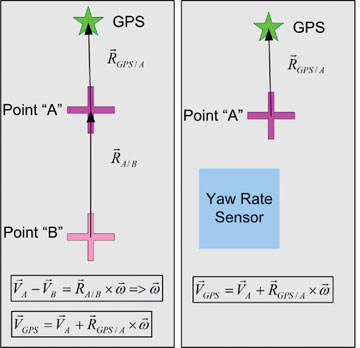
A commercial off-the-shelf sensor designed for measuring vehicle and/or tire slip measures vehicle 2D velocity. Yaw rate can be measured either with an inertial rotational rate sensor or a second 2D velocity sensor. Yaw rate measured using a pair of these 2D sensors eliminates the rate bias and rate bias drift associated with inertial sensors. Figure 3 shows both configurations.
FIGURE 3 Two approaches to VBAS to mitigate DGPS outages. The diagram on left shows implementation with two 2D velocity sensors to determine vehicle yaw rate. Computationally, this is attractive as senor drift need not be considered. The diagram on the right shows an implementation with one yaw rate sensor, and one 2D velocity sensor. This is the configuration operating for the UPA; it requires yaw rate sensor drift compensation to provide accurate measures of vehicle yaw rate.
An accurate measure of vehicle heading at the time GPS positioning is lost is critical to the augmentation process. A performance goal of 20 centimeters tolerable error at the end of a 15-second outage for a vehicle traveling at 25 miles per hour (11.2 meters/second) requires a heading estimation error of no more than 0.07 degrees (that assumes the only source of error is attributable to the heading).
GPS outages (time from loss of position to reacquisition) attributed to passing under overpasses range from 7 seconds (single bridge) to 9 seconds (double bridge). The IV Lab augmentation system reliably provides sufficiently accurate position and heading estimates to carry through these outages. At the present level of performance, should an outage last more than 15 seconds, the accuracy of the augmentation system cannot be guaranteed. In this event, the driver is alerted, and the DAS is deactivated until a DGPS position fix is reacquired. Fortunately, since new receiver firmware was installed, no instances of an outage exceeding 15 seconds have occurred during two months of test, evaluation, and driver training.
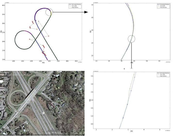
Figure 4 illustrates the accuracy of the VBAS system. At the time the fix solution is reacquired on the exit ramp, the lateral error between the fix solution and the position estimated by the VBAS is approximately 10 centimeters. This accuracy is sufficient to allow a driver to travel on the entrance ramp even during zero-visibility conditions.
Figure 4. Example of VBAS as a bus operates on the Cedar Avenue/Old Shakopee Road overpass. Bus trajectory is northbound on Cedar, exiting westbound Old Shakopee Road, then entering southbound Cedar Avenue from Old Shakopee Road. Upper left shows northbound trajectory and loss of satellite lock. Upper right shows reacquisition of DGPS, float, and fix states of the DGPS receiver. Lower right shows accuracy of VBAS system compared to DGPS when DGPS reacquires fix. Lateral error of VBAS at at the time the fix is reacquired is approximately 10 centimeters. Lower left shows satellite view of the interchange.
Driver Training
Bus-only shoulder operation has proven itself safe and, in fact, safer than normal transit operations, according to recent data. The goal of driver training is to prepare drivers to use the DAS system to enable them to safely use the bus-only shoulders in conditions under which they normally would not.
A rigorous training protocol developed in cooperation with the University of Minnesota HumanFIRST program, Schmitty and Sons Transportation driving instructors, and MVTA involves both simulator-based and on-road training.
Simulator-Based Training
Beefore using driver assist systems, bus drivers are continually taught that the driver controls the bus and is responsible for both the passengers and vehicle. Drivers take this responsibility seriously, and as such, develop skills and techniques that guarantee safe passage under all conditions, even when running on narrow, bus-only shoulders.
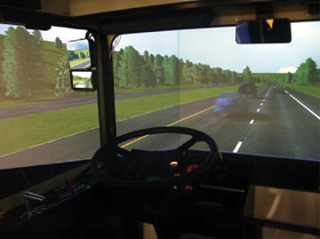
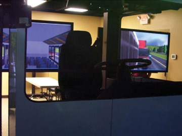
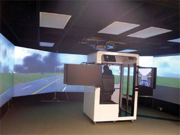
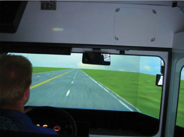
To best prepare drivers for using the DAS under difficult conditions, a high-fidelity driving simulator was commissioned. A DAS was installed in the simulator, and an interface to the simulator was created. In this context, a driver has the ability to train in normal and abnormal (low to zero visibility) conditions before beginning on-road DAS training and use.
In the simulator, the driver learns that the system only provides assistance; responsibility for the safety of the bus and passengers still resides with the driver. Experience with Alaskan snowplow operations, where formal training is limited to a few on-road test drives, has shown that a driver may take a few winter seasons to fully accept the system. This delayed acceptance is in part attributable to the fact that for six months per year a driver has no opportunity to train with the system. Acceptance gained over one winter season is lost during the summer.
The simulator installed at an MVTA bus garage uses a seat-based motion platform to achieve realistic vehicle dynamics. The DAS installed in the simulator allows a driver to train in all weather and traffic conditions on a geospecific roadway before transitioning to a DAS-equipped bus. Geospecificity is achieved through the creation of virtual worlds based on roadway data collected by the mapping vehicle shown earlier.
Bus-driving simulator at the MVTA bus garage in Burnsville, Minnesota.Bus-driving simulator at the MVTA bus garage in Burnsville, Minnesota.Bus-driving simulator at the MVTA bus garage in Burnsville, Minnesota.Bus-driving simulator at the MVTA bus garage in Burnsville, Minnesota.
On-Road Training
After a driver both demonstrates an
d acknowledges comfort and competence with the DAS in the simulator, training transitions to the actual route on which the buses will operate. Each of the 10 buses is equipped with a six-camera data-acquisition system. The six cameras capture not only the driver’s actions (hands, face, feet), but also views of the road (front, left, and right sides.)
Drivers travel with an instructor. The onboard data acquisition system can be used to reconstruct particular scenarios as a means to offer advice as to how the driver and system can better interact in difficult driving and traffic conditions.
On-road training benefits system developers as well. Training offers a driver an opportunity to test the system in real-time on an actual road. The perspective a driver brings is generally different than that of the developer, and the insights the end user provides typically produce a better system. As an example, driver experience with the system during the initial training period produced the staged approach to lane-departure alerts previously described.
Conclusion
The IV Lab, MVTA, and Schmitty and Sons Transportation will soon release 10 DAS-equipped buses into revenue service to support narrow bus-only shoulder service between downtown Minneapolis and Apple Valley, Minnesota. Although the IV Lab has deployed a number of DAS-equipped vehicles, this UPA deployment represents the first time that the system has been used to transport passengers. This deployment should prove that although DGPS systems are susceptible to periodic outages, a properly designed and executed augmentation system will provide a sufficiently robust system that will be accepted by both drivers and passengers. It will also demonstrate to other transit agencies that even narrow rights of way offer significant transit advantages at low cost, and that potential operational difficulties can be overcome through the use of DAS technologies.
Manufacturers
The buses carry Trimble R7 receivers and Ibeo Lux multi-plane scanning LIDAR sensors. The IV Lab VRS network is based on six Trimble NetR5 receivers. The server runs Trimble’s GPSnet and RTKnet applications, with the Trimble Integrity Manager.
Craig Shankwitz is the director of the Intelligent Vehicles Laboratory at the University of Minnesota.
By Jürgen Rossmann, Petra Krahwinkler, and Markus Emde
Modern machines such as wood harvesters can automatically cut trees and remove branches, but an expert is still needed to plan a thinning and to mark the trees to be felled. The process can be accelerated if the forest ranger can virtually mark trees to be cut, using geographic coordinates instead of colored crosses sprayed on the stems. This requires the robotic wood harvester to be able to locate itself accurately to enable automatic navigation to the next tree for cutting.
Absorption of the GPS signal in the forest canopy leads to poor results, however, with errors up to 50 meters and more. Furthermore, the canopy may cause interruptions and signal loss for several seconds. The performance can be even worse on a moving vehicle, where the signal may even get lost until the vehicle reaches an open area or stops.
Other approaches use differential GPS (DGPS) sensors as their main source of position information. However, our experiments using a high-precision DGPS sensor showed that its accuracy is not even close to sufficient for navigating to a single tree. As the DGPS suffers from the same canopy-related disturbances and shielding, it cannot benefit from its theoretical advantages. In pratice, the DGPS system did not update its position at all when signal reception became too weak.
A different approach was needed. We found it in the framework of the Virtual Forest, more precisely in the semantic modelling of forests, where techniques are being developed to delineate single trees from remote sensing data, such as airborne laser scanner data. Along with the trees and their geo-coordinates, the height and the diameter at breast-height are determined. This data can be used to generate a tree map, which can be used for navigation. The map has a mean error between 0.5 and 1.5 meters, which is still below the mean tree distance of about 2.5 meters.
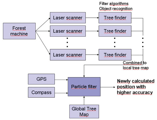
Visual GPS. The idea of Visual GPS is to bring current developments in the field of robotics into the forest and combine them with information on forest inventory so that the result outperforms other navigation approaches. A matching algorithm is run based on a tree map, generated from remote sensing data, and the tree group, which was detected by one or more laser scanners.
We then implemented a particle filter algorithm, as it enables considering different kinds of distributions. Particles are also called random state samples, and each particle is a hypothesis as to what the true world state might be.
In the initialization, particles are distributed uniformly. An importance weight wt is calculated for each particle, incorporating the measurements as described below. A sampling step rejects particles with a low importance weight and replaces them with new particles, which are distributed according to the previous map. This process is repeated until the particle distribution concentrates at one point, and the particle with the highest weight is returned as the result (see Figure 1).
Figure 1. Particle concentration after resampling; wood harvester at center.
A single tree as a landmark cannot be associated with its corresponding tree in the map. However, patterns of tree positions can be matched. We chose a square area to guarantee even particle distribution and short calculation time. Each particle represents a hypothesis for the position of the vehicle and is tested for its probability to represent that position.
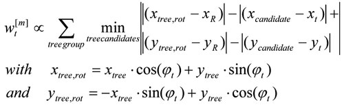
To make the approach more robust against faulty tree maps, we implemented a rotation variant approach, determining vehicle heading along with its position. This enhanced the probability measure used in the propagation step. Instead of embracing only the distances of the trees to the reference point, their relative position is used, considering the heading wt of the current particle:
This approach directly calculates vehicle heading, but the sensitivity towards rotation, which results from the new probability measure, leads to a higher number of particles that must be used during the initialization step.
Global Search. Experiments on a test area with about 22,700 trees proved that the algorithm worked reliably for tree groups containing 20 or more trees, and for position errors of the magnitude of the mean tree distance. Similar tree groups could not be found within the forest. However, the calculation time was too long to be used for navigation.
Local Search. To overcome the high calculation time, we reduced the number of particles. The initial position is estimated with an ordinary GPS sensor. Although the GPS measurement is faulty in the forest, it can limit the search to a restricted area. Machines most often start at the edge of a forest stand, at a forest road, or a canopy opening. At these spots the canopy usually is transparent, and GPS sensors work with higher precision. Therefore, they provide a good initialization for the algorithm.
Robotic wood harvester.
In the following steps, the previous position can be used instead of the output of the GPS sensor for determining the search area. The previous position provides a better initial pose estimation than the GPS sensor and therefore gives the opportunity to further decrease the search area.
To reduce the number of trees for which the distance has to be calculated, trees with a distance from the initial pose estimation smaller than the sum of the estimation of the maximal position error and the maximal distance of the trees in the scanned tree group from the reference position are extracted from the tree map.
Another way to reduce the search area is to estimate vehicle orientation. This is difficult for machines such as wood harvester, which moves slowly and stops frequently when cutting trees. Therefore, small lateral position differences result in large orientation deviances, as the difference vector does not directly point into the direction of the movement any more. Another approach is to use sensor fusion and mount a compass onto the vehicle. During particle initialization, the angle can be restricted to the domain of uncertainty around the compass orientation. However, mounting a compass onto a wood harvester proved to be a serious problem, as the harvester’s massive metal body disturbs the compass measurement.
Figure 2 shows the workflow of the complete system.
Figure 2. Navigation system components.
Results
The simple criterion presented here proved to be reliable in the vast majority of cases. Problems can occur when the tree group contains trees that are not part of the tree map (false positive). This can happen due to missing trees in the tree map or faulty tree cognition in the local laser scanner measurement. In the first case, the understory might not have been detected in the airborne laser scanner data. In the second case, other objects like the harvester’s aggregate might have been mistaken for a tree.
The case of trees not detected in the local laser scanner measurements but contained in the tree map (false negative) does not create problems in the pose estimation step. The algorithm searches for a corresponding tree for each unit in the tree group. For a false positive, no corresponding tree can be found, whereas a false negative is simply not considered. However, if the size of the tree group is too small, the estimation errors grow. The minimum number of trees depends on the search area radius. A size of 20 trees proved to generate reliable pose estimations even during the global search. Dropping below 15 trees, the number of faulty position increases rapidly as more similar patterns can be found.
Single faulty positions can be filtered with respect to the movement constraints of a harvester. The velocity is very low, and the orientation cannot jump. In the experiments, cycle times of about 0.5 seconds were reached on a standard PC. As forest machines do not demand very short calculation time, the algorithm proved to run fast enough to allow identification of single felled trees onboard real machines. One application of the algorithm was to support a navigation assistant to the next tree, similar to navigation systems in cars.
To evaluate system accuracy on a real wood harvester, a surveyor’s office was instructed to measure the vehicle’s position at seven distinct locations. At each position, the sensor input data was written to file for several seconds. This data was evaluated, and for each location more than 45 pose estimations were calculated. The mean value of the position error amounted to approximately 0.55 meters.
Future Work
Reliability can be enhanced by using a detailed digital ground model and the cabin tilt in order to detect the area where the laser beams hit the ground, and therefore avoid the detection of false positives. Similarly, the position of the aggregate, which can be measured by integrating sensors in the hydraulic cylinders of the crane, can be cut from the laser scanner measurements and ignored during tree detection, further reducing the amount of false positives in the tree group. With the integration of an outlier rejection step for false positives in the detected tree groups that ignores trees for which no corresponding candidate tree can be found, a more accurate importance factor can be calculated.
Another task is the integration of the algorithm with a Kalman filter to allow real-time performance of the algorithm. Therefore, the Kalman filter is initialized with the pose estimation of the particle filter algorithm, which is also used for continuous checks of the current position estimate, thereby combining two algorithms with different advantages. The Kalman filter allows real-time execution and therefore speeds up the overall navigation algorithm. The particle filter algorithm can periodically check the position estimated by the Kalman filter and correct it. Furthermore, it provides a strong method to cope with two main problems in mobile robotics: the data association problem and the kidnapped robot problem.
Simultaneously, a mapping and map-correction algorithm could be integrated into the system so that understory trees, which cannot be detected using remote sensing data, and deciduous trees, which are more difficult to delineate in airborne laser scanner data, can be added to the tree map.
Jürgen Rossmann is head of the Institute of Man-Machine Interaction at the RWTH Aachen University, where Petra Krahwinkler and Markus Emde are research scientists.
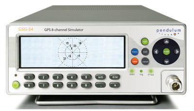
Spectracom’s new 8-channel GPS constellation simulator, the Pendulum GSG-54, provides a wide-range of capabilities for in-line production testing of devices integrating GPS receivers due to its ease-of-operation and fast test cycles. Its versatility also supports engineering organizations’ efforts for integrating GPS receivers into devices under development.
The Pendulum GSG-54 simulates the satellite signals detected by a GPS receiver. It comes in a bench-top chassis that is compact and portable. It offers built-in standards-based test scenarios that can be initiated or modified on the fly from the intuitive front panel interface, and offers a variety of connectivity options to control and reconfigure test parameters.
The GSG-54 GPS constellation simulator builds on the features available from Spectracom’s GSG-L1 single-channel GPS signal generator that offers simple but fast assembly verification for functions such as antenna connectivity, receiver operation, or satellite signal identification. The GSG-54 provides for many more test cases due to its ability to simulate eight different satellite signals to test position accuracy, sensitivity to loss of satellite signals, timing accuracy, and dynamic range. It can simulate movements and user trajectories, multi-path scenarios and various other atmospheric conditions.
Spectracom’s new 8-channel GPS constellation simulator, the Pendulum GSG-54, provides a wide-range of capabilities for in-line production testing of devices integrating GPS receivers due to its ease-of-operation and fast test cycles, according to the company. Its versatility also supports engineering organizations’ efforts for integrating GPS receivers into devices under development.
As more and more electronic devices integrate GPS receivers, manufacturers require instrumentation to fully test the GPS capabilities of each device on the manufacturing floor. According to Staffan Johansson, Spectracom product manager, “We understand the need for high-throughput manufacturing testing of GPS receivers. A multi-channel GPS simulator must be easy to use, yet powerful enough to confirm each device’s performance under a variety of real-world conditions.”
The Pendulum GSG-54 simulates the satellite signals detected by a GPS receiver. It comes in a bench-top chassis that is compact and portable. It offers built-in standards-based test scenarios that can be initiated or modified on the fly from the intuitive front panel interface, and offers a variety of connectivity options to control and reconfigure test parameters, Spectracom said.
The GSG-54 GPS constellation simulator builds on the features available from Spectracom’s GSG-L1 single-channel GPS signal generator that offers simple but fast assembly verification for functions such as antenna connectivity, receiver operation, or satellite signal identification. The GSG-54 provides for many more test cases due to its ability to simulate eight different satellite signals to test position accuracy, sensitivity to loss of satellite signals, timing accuracy, and dynamic range. It can simulate movements and user trajectories, multi-path scenarios and various other atmospheric conditions.
“Like our other products, the GSG-54 offers the lowest cost of ownership for manufacturers and development engineers by providing complete testing of multi-channel GPS performance with high throughput and ease-of-use without unnecessary complexity or expense,” said Lisa Withers, president and CEO of Spectracom.
The U.S. Army’s Autonomous Platform Demonstrator, or APD, is a 9.6-ton, six-wheeled, hybrid-electric robotic vehicle currently undergoing developmental and mobility testing at Aberdeen Proving Ground, Maryland. According to an Army statement, the demonstrator vehicle represents the state of the art in unmanned ground vehicle mobility technology.
With its advanced hybrid-electric drive train, the 15-foot-long vehicle, being developed by the U.S. Army Tank Automotive Research, Development and Engineering Center (TARDEC), can achieve speeds of more than 50 mph.
When equipped with its autonomous navigation system, the APD is configured with GPS waypoint technology, an inertial measurement unit and computer algorithms which enable it to move autonomously at speeds up to 50 mph while avoiding obstacles in its path.
“The vehicle has obstacle detection and avoidance technology,” said Jim Overholt, senior research scientist in robotics at TARDEC.
The mobility testing is aimed at advancing and developing the robot’s ability to maneuver at higher speeds while maintaining extreme terrain-ability at lower speeds.
“We’ve run it through courses, slope testing and brake testing,” said Chris Ostrowski, associate director for Vehicle Electronics and Architectures at TARDEC.
The APD is currently testing high-speed maneuverability, such as lane changing. “This is a challenging controls problem with a skid steer vehicle. We want the robot to be stable when performing maneuvers like this, but we also want it to retain the other mobility characteristics that it possesses at lower speeds,” said Ostrowski.
Other mobility characteristics include the ability to climb a one-meter step, navigate a 60-percent slope, and pivot turn in place.
Being a series hybrid-electric vehicle, the APD is propelled by six in-hub electric motors and has a diesel generator which charges its lithium ion batteries.
“The state-of-the-art hybrid-electric drive train is just one of the mobility technologies we are demonstrating with this platform,” said Andrew Kerbrat, APD project manager, TARDEC.
Other technologies being demonstrated include advanced suspension systems, thermal and power management systems, robotic safety systems, and lightweight hull technologies.
“We’ve made a lot of progress with this platform in a short time period. From concept to wheels on the ground was just a shade over two years, and in the eight months since then, we’ve driven almost 3,000 kilometers and have demonstrated 95 percent of the metrics that we were trying to show with this platform,” said Kerbrat.
APD is the mobility platform being used by the Robotic Vehicle Control Architecture, or RVCA Army Technology Objective, also out of TARDEC. Working with PEO-Integration, RVCA has integrated a suite of system control, display and sensing hardware and software onto APD that allow it to be controled real-time by a Soldier, or operate in an autonomous mode.
“It uses a variety of sensors and a Ladar — a laser/radar scanning radar that can detect moving objects at distances,” said Overholt. Additionally, RVCA provides Reconnaissance Surveillance and Target Acquisition capabilities.
“It has a four-meter mast with a sensor ball on top so it goes up pretty high and can see out quite a ways,” said Chris Ostrowski.
“When you combine the autonomy and control capabilities provided by RVCA with the extreme mobility characteristics of APD, it allows the Soldier operator to quickly deploy a mission payload precisely where he wants it, and over some very tough terrain,” said Kerbrat.
“The bottom line is that we are providing the soldier with a significant capability that will assist him in the performance of his mission, while keeping him safer in the process.”
INRIX announced the upcoming release of a new iPad version of INRIX Traffic!, its popular app for commuters.
Using the MDK (mobile developer kit), INRIX completed development of an iPad optimized version of its popular INRIX Traffic! and INRIX Traffic! Pro app in less than 2 weeks. Coming later this month to the iPad App Store, INRIX Traffic! is a free app that provides real-time traffic, traffic forecast, speed trap, accident and incident information for all major cities and roads across the U.S. and Canada. Winner of a 2010 MacWorld Best of Show Award, INRIX Traffic! Pro is available as an in-app upgrade to the free app that provides motorists with the added benefit of always knowing the fastest route, best time to leave, travel time and ETA for any destination.
“Our mobile apps and tools have helped companies like Ford and providers of 8 of the top 10 most popular GPS smartphone navigation apps get to market fast with new traffic-powered navigation services,” said INRIX President and CEO Bryan Mistele. “Bill’s experience helps us transform our unique consumer insights into new features that extend beyond INRIX Traffic! to apps that empower our partners and customers to deliver consumer experiences that make navigation more useful every day.”
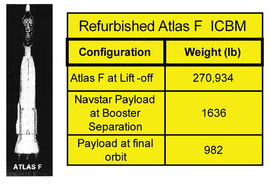
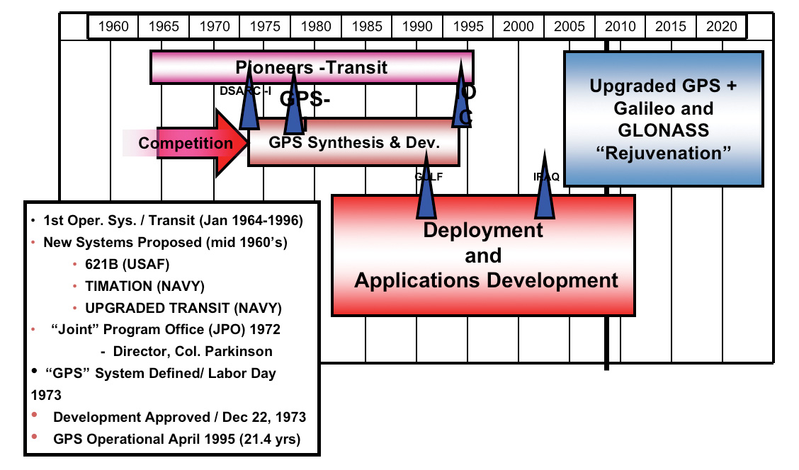
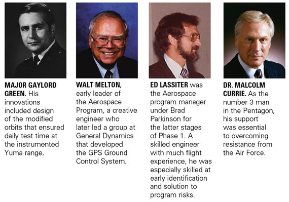
By Bradford W. Parkinson and Stephen T. Powers, with Gaylord Green, Hugo Fruehauf, Brock Strom, Steve Gilbert, Walt Melton, Bill Huston, Ed Martin, James Spilker, Fran Natali, Joe Strada, Burt Glazer, Dick Schwartz, Len Jacobson, AJ Van Dierendonck, and others.
GPS Phase I program approval meant that the real work could begin. The conclusion of a two-part history, told by the people who made it.
By January 1974, the GPS program at the Joint Program Office (JPO) was well underway. With only about 30 officers, the workload was enormous. Fortunately, the Aerospace cadre of about 25 also made extraordinary contributions. In a flurry of activity, the team developed requests for proposals, made top-level specifications, and published initial interface control documents. The work of converting viewgraphs into real hardware, as many know, is an exacting and sometimes painful process.
Of course there were many challenges, but five of them, principally engineering, stand out as particularly daunting. These were:
Defining the specific details of the GPS CDMA signal structure;
Achieving rapid and accurate satellite orbit prediction;
Ensuring and demonstrating spacecraft longevity approaching ten years;
Developing a full family of GPS user equipment.
We discuss each challenge in detail, including the names of those most instrumental in meeting them. The first appearances of their names are highlighted, although if they appeared in Part 1 of this story (May 2010 issue), their names are not highlighted.
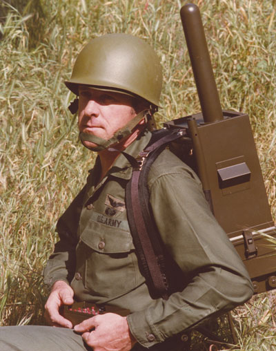
EARLY GPS MANPACK worn by JPO Army deputy Lt. Col. Paul Weber. This photo graced the cover of the first-ever GPS brochure! (Credit: Bradford W. Parkinson and Stephen T. Powers)
Challenge 1.Defining the specific details of the GPS CDMA signal structure (coherence, acquisition, spreading, communication protocol, structure, error correction, message structure, and so on).
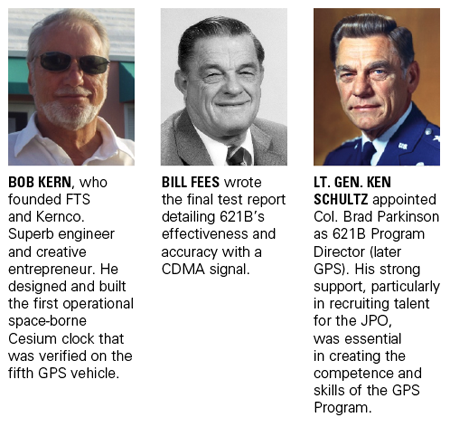
The selection of the GPS signal structure was broadly confirmed with the tests that were run by program 621B at the White Sands Missile Range with the help of Joe Clifford, Bill Fees, and Larry Hagerman, all from the Aerospace Corporation.
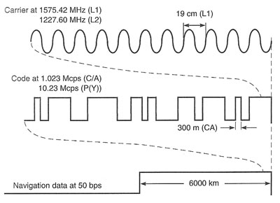
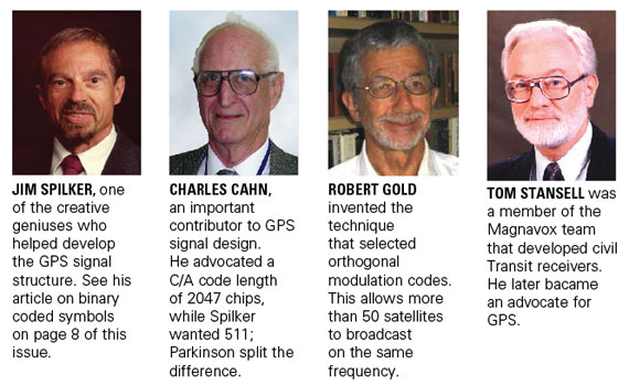
While the fundamental decision to select CDMA had been made during the Lonely Halls meeting, a vast number of details had yet to be worked out. Fortunately, there were many earlier studies of the signal. Dr. Jim Spilker (then of Philco Ford), who had also written the major reference book on digital communications, authored one of the studies. Dr. Charles Cahn, Nat Natali, Burt Glazer, Ed Martin, and Dr. Robert Gold of Magnavox all made significant contributions. One of the most important details was the decision that the carrier, code, and data of the GPS signal would all be phase-coherent (Figure 1). As discussed later, this decision enabled much of the precision that we now see in advanced GPS receivers.
FIGURE 1. GPS signals were designed to be all aligned as transmitted, that is, coherent. (Courtesy Misra and Enge, Global Positioning System).
The exact Gold codes family had to be selected from the original family, since Dr. Gold’s technique did not include the natural Doppler shifts. The data message was integrated into both the civil (C/A ) and military (P/Y) signals through inversion of their codes every 20 milliseconds.
To work out the details of the data message, the JPO had a strong team including Major Mel Birnbaum, Col. Brock Strom, and Capt. Bob Rennard. Outside contractors making major contributions included Dr. Fran Natali, Dr. A. J. Van Dierendonck, and others. Van Dierendonck played a particularly effective role in helping define “GPS time.” This sounds rather mundane, but had some very interesting complexity. Jim Spilker recommended the 1023-bit message length to avoid a correlation problem associated with Doppler shifts (this recommendation was incorrectly attributed in the last issue).
The data stream came down at 50 bits per second. Through this tiny pipe of information, all the precision of GPS had to pass. It included the space-vehicle orbit-position information (ephemerides), system time, space-vehicle clock-prediction data, transmitter status information, and C/A signal handover time to the P/Y code. Also as a part of the message, ionospheric-propagation delay models were incorporated for the single-frequency user. Further, to aid rapid acquisition of new satellites just rising over the horizon, the ephemerides of all other satellites in the full constellation had to be included. Each digital word had to be defined in terms of scaling, bias offset, and precision in terms of the number of bits transmitted.
About 95 percent of the GPS message has endured with no changes needed at all. In a few cases, because the newer user equipment is more accurate, greater precision is desirable. It is a great tribute to the brilliant engineers and scientists who designed the signal structure in 1975 that it has endured for 35 years with so little need for modification.
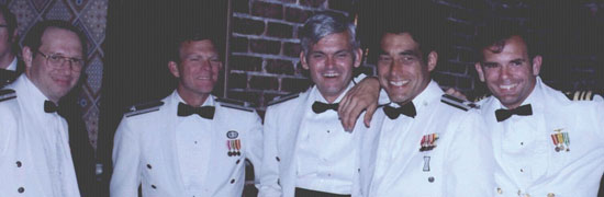
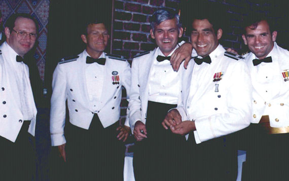
Some of the JPO Heroes at a “dining-in,” a recognition dinner. From left, Major Mel Birnbaum (made many important contributions. He was famous for marathon code reviews that could last 18 hours straight. He hated to miss schedules!); Col. Don Henderson (later Maj. Gen.) second Air Force deputy; Major Ralph Tourino (later Maj. Gen.), Program Control; Lt. Col. Ken Juvette. director of procurement; and LCdr. Joe Strada, a key leader in the extensive test program. (Credit: Bradford W. Parkinson and Stephen T. Powers)Credit: Bradford W. Parkinson and Stephen T. Powers
Challenge 2. Developing space-hardened, long-life, atomic clocks (qualified for the upper Van Allen Belt, with 4- to 5-year lifetime requirement for individual clocks).
In 1966, both the Air Force and the Navy recognized that developing a precise, stable time-base for generating the one-way (passive) navigation ranging signal in the satellite was essential. Cesium atomic clocks had been invented, demonstrated, and offered for commercial sale by the middle of the 1950s, before the Space Age. The major commercial issues with these clocks were that they tended to be bulky, power-hungry, and not hardened against space radiation. To address that problem, rubidium atomic clocks, noteworthy for their small size and low power requirements, were developed. Still, the issues of mechanical and radiation hardening as well as temperature sensitivity had to be resolved before they could be used in space.
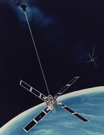
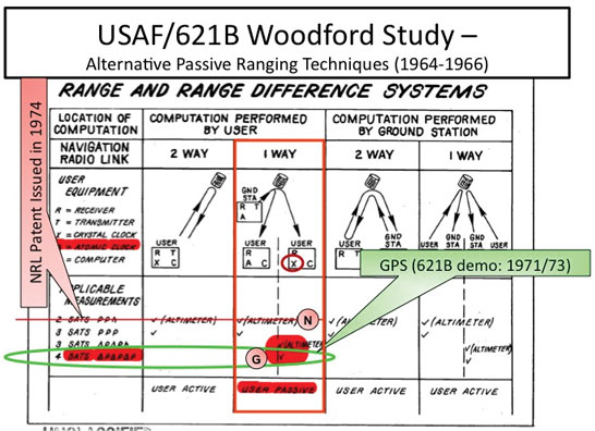
The 621B/Woodford/Nakamura study of 1964/66 called for atomic clocks in the satellites in at least seven places. The study advocated a technology program to space-harden existing clock technology. Unfortunately, the Air Force chose not to pursue a space atomic-clock technology program.
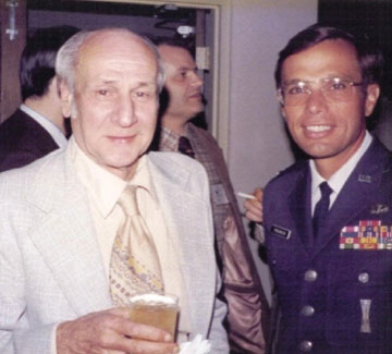
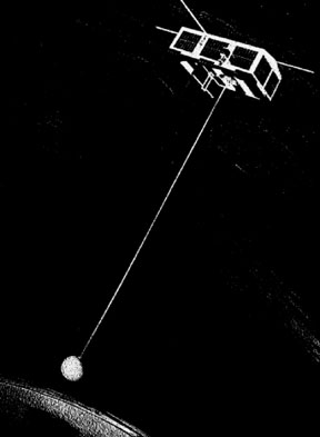
However, the Naval Research Laboratory (NRL) did institute a program in 1964. It pursued the technology for stable clocks with a series of satellites that have already been discussed. The first Timation satellite, launched in May 1967, carried a quartz clock. Not surprisingly, the frequency varied substantially with satellite temperature. The second Timation satellite also contained a quartz clock as well as a temperature controller and showed improved operation, but the results still fell short of those necessary for a GPS satellite. The third satellite in the series had not been launched before the Pentagon approved GPS development in December 1973. In any case, Timation 3 was designed to carry two slightly upgraded, off-the-shelf commercial rubidium clocks.
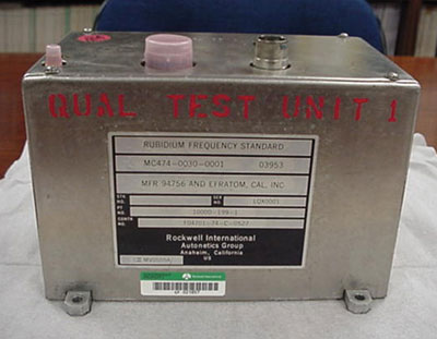
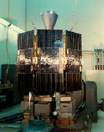
Qualification Model of the first GPS atomic clock, built by Rockwell International working directly with Efratom, a small German company. (Credit: Bradford W. Parkinson and Stephen T. Powers)
Based on the progress that NRL had made, during the Lonely Halls meeting the JPO decided to commit to atomic clocks in the first operational GPS satellites. This third Timation satellite was renamed NTS-I and came under the newly formed Joint Program Office for GPS. The satellite was launched on July 14, 1974, as a part of the GPS program. However, the ineffective attitude-stabilization system caused varying sun angles and hence, significantly varying temperatures, masking any careful evaluation of the rubidium performance.
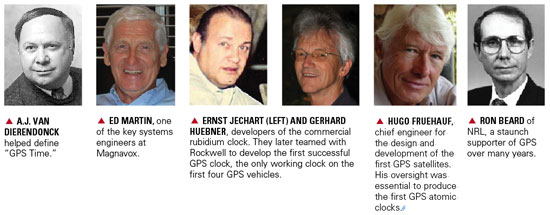
The GPS space-based rubidium atomic clock technology was derived from a unit produced by Efratom, a small company initially based in Germany. The geniuses behind this creative device were Ernst Jechart and Gerhard Huebner.
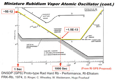
By the summer of 1974, a satellite contractor, Rockwell International (RI), had been selected to build the GPS operational satellites. Included in the program direction by the JPO was a separate development of rubidium clocks for the satellites as an alternative to the NRL cesium clock effort, in case the NRL effort faltered. Hugo Fruehauf of Rockwell had independently discovered and contacted Efratom, the company that NRL was working with, although his interaction was totally independent of that of the NRL. In addition, Fruehauf’s relationship with Efratom was simplified because of his fluency in German, since Jechart did not speak English, and Efratom had just established an office in Southern California near the Rockwell developers. Figure 2, a page from the original Rockwell proposal, shows the excellent ground test data at both 1000 seconds and at 24 hours.
Figure 2. Test results for the Rockwell proposed GPS space-hardened prototype atomic (rubidium) clock, based on the Efratom commercial clocks. (Credit: Bradford W. Parkinson and Stephen T. Powers)
On realizing that the small Efratom company would be incapable of producing a radiation-hardened, space-qualified rubidium oscillator, RI’s GPS satellite program manager Richard Schwartz created a teaming relationship with them, which included his chief engineer, Hugo Fruehauf, plus Dale Ringer, Dr. Chuck Wheatley of Rockwell’s Autonetics Division, and Efratom’s Werner Weidemann. With heroic efforts, this team built a space-qualified clock in time for the first GPS launch in February 1978.
Meanwhile, the NRL-sponsored development of a cesium clock by FTS ran somewhat behind schedule. Their cesium clock was not available for the first three GPS satellite launches. The first NRL hardened clock was included on the fourth GPS satellite; unfortunately that unit failed after 12 hours of operation because of a power-supply problem. As a result, the only operating clocks on the first four GPS satellites were those developed by the Joint Program Office through its contractor Rockwell International. The decision to proceed to full-scale development for GPS, called DSARC 2, was made before any NRL-developed clocks had become operational.
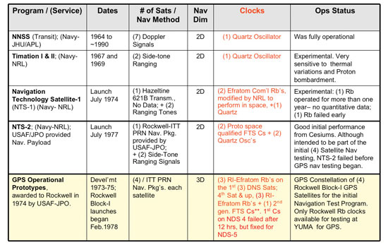
That said, the NRL-sponsored FTS cesium clocks were available for later satellites, and performed extremely well. Later Block II GPS satellites carried two rubidium-frequency standards made by Rockwell and two cesium-frequency standards (primary source, Frequency and Time Systems; secondary sources, Kernco and Frequency Electronics Inc., on selected vehicles). Figure 3 summarizes the early clock program.
Figure 3. Earliest satellite-clock technology developments, culminating in the last row: four Rockwell satellites with Rockwell-developed rubidium clocks. (Credit: Bradford W. Parkinson and Stephen T. Powers)
In spite of NRL’s development difficulties, GPS users owe a debt to the lab for its pursuit of this technology. Clearly GPS would not have performed so well without space-hardened atomic clocks. It was the apparent NRL progress that strengthened the argument. The support of Ron Beard of NRL in this joint effort has been invaluable to the program over many years. More than 450 atomic frequency standards have now flown in space. By far the greatest user has been GPS.
Challenge 3.Achieving rapid and accurate satellite orbit prediction, to within a few meters of user ranging error (URE) after 90,000 miles of travel.
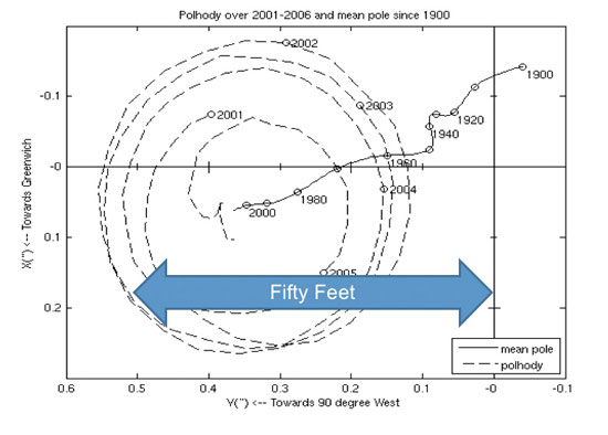
Since the GPS system architecture had upload stations only on U.S. soil, the satellites were out of sight for many hours, making accurate prediction of their orbits essential. To achieve the expected positioning accuracy, the orbit prediction had to contribute less than a few meters of ranging error after 90,000 miles of travel. Achieving this standard was a major challenge in the early days of GPS. Such a prediction must account for the complications of Earth pole wander, Earth tides, general and special relativity, the noon turn maneuver of the satellite, solar and Earth radiation, and the reference station’s location. Figure 4 gives an example of the problems of polar wander.With roughly a 400-day period, this effect had an amplitude of many tens of feet. While this wander has to be included in the GPS orbit-prediction model, fortunately GPS is the major technique to measure it.
Another, usually unrecognized feature is that the monitor stations only use the GPS signal for ranging. In other words, they are passive, rather than using the usual technique of that era, two-way ranging. The reference receivers were of a special design, developed by Jim Spilker’s company, STI. They successfully received the first signal from the Rockwell/ITT satellite (NDS-1) on March 5, 1978, after its launch on February 22, 1978.
Fortunately, the Transit program had pioneered precise orbit prediction and had taken these effects into account. Its Astro/Celeste program, developed by Bob Hill and Dick Anderle at the Naval Surface Weapons Center in Dahlgren, Virginia, batch-processed the measurements taken by the reference stations. Unfortunately, this processing would take too long to provide the most up-to-date predictions.
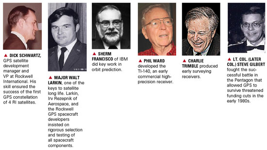
A new scheme was devised that included partial derivatives of prediction relative to reference-station measurements. A.J. Van Dierendonck applied his knowledge of filters to help lead development of these calculations, which allowed a modified (linearized) Kalman filter to be used for near-real-time optimal prediction. Bill Fees of Aerospace, Walt Melton of General Dynamics, and Sherm Francisco of IBM, among others, implemented these techniques. The initial master control and upload stations were located at Vandenberg Air Force Base, since moved to Schriever Air Force Station; a backup master control station has been re-established at Vandenberg.
Figure 4. Motion of the Earth’s spin axis must be included in the measurement parameters for GPS satellite location. The broadcast ephemeris is adjusted to include this effect, so the user need not make further adjustments. (Courtesy of International Earth Rotation and Reference Service). (Credit: Bradford W. Parkinson and Stephen T. Powers)
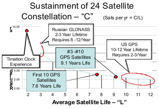
Challenge 4.Ensuring and demonstrating spacecraft longevity approaching 10 years (the issue was GPS affordability)
The issue was simply that sustaining a constellation of 24 satellites would be prohibitively expensive if the satellites did not have long lives. Again, the Air Force/621B study by Woodford and Nakamura in 1966 focused on the problem: “The most specific change in satellite technology is the increase of mean time before failure (MTBF). MTBFs on the order of 3 to 5 years can now be considered feasible.”
The problem is easily illustrated in Figure 5. The light blue line shows the trade-off between average satellite lifetime, L, and the required number of satellites per year for a 24-satellite constellation. GLONASS, the Russian system competing with GPS, has the experience shown in the upper white box. With satellite lifetimes averaging two to three years (or less), GLONASS has a corresponding requirement for eight to 12 satellite launches per year. Only a very wealthy country can sustain such a launch program.
Figure 5. The imperative for long satellite lifetimes. (Credit: Bradford W. Parkinson and Stephen T. Powers)
The red oblong illustrates the U.S. GPS experience, which requires only two to three launches per year. Also shown is the initial experience of GPS during Phase I. The first 10 GPS satellites reached an average age of 7.6 years, with #3 and #10 exceeding 9 years. This is an enormous credit to Rockwell International and in particular the program manager Richard Schwartz. He had excellent system engineering support from Andy Codik. The JPO satellite division was intially led by Major Gaylord Green and later by Maj. Doug Smith, with help from Capt. Jack Henry.
Three factors are key to long-lived satellites:
Designs with carefully selected redundancy (for example, clocks, power amplifiers),
Enforcing a rigorous part-selection program including the de-rating of parts (must be class S. or equivalent),
Testing as you fly and insisting on a detailed analysis of all failures.
Figure 5 also illustrates why the Timation clocks could not be used as prototypes for the GPS program. In general, their maximum lifetimes were approximately one year. Clearly their designs needed greater maturation.
The demonstrated lifetimes were essential to passing the next milestone, DSARC II, which allowed GPS to proceed to full-scale development.
Challenge 5.Developing a full family of GPS user equipment that capitalized on the digital signal (leading to inexpensive digital implementation) and spanned most fundamental military uses, as well as demonstrating civilian cost feasibility.
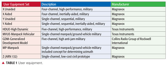
The last, but certainly equally difficult of these five engineering challenges, was the development of nine different types of GPS user equipment. Recognize that a major part of the challenge was to stuff the real-time digital software processing into the relatively primitive digital computers of that era. Table 1 summarizes the development of user equipment:
Data: Bradford W. Parkinson and Stephen T. Powers
All of the sets performed well within specification. They were characterized, however, by large size and heavy power demands. Magnavox, under the technical direction of Vito Calbi, produced the largest variety of user equipment. It was a subcontractor to General Dynamics, who reported directly to the JPO. At Aerospace, Frank Butterfield was a gifted contributor, particularly skilled at practical antenna design.
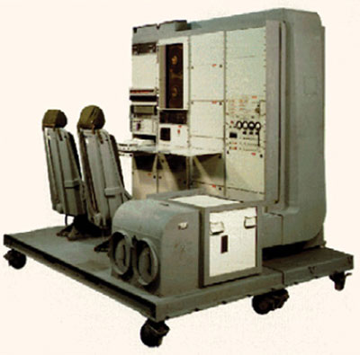
The Generalized Development Model (GDM) reciever, developed by Rockwell Collins Group, was the largest of the sets, created for a specific purpose: to demonstrate the ultimate jam resistance for GPS user equipment. It attained performance better than 100 db jamming-to-signals ratio (J./S) in actual flight test. The GDM receiver achieved this by integration with inertial components, directional antennas, and shading with the aircraft body. Such a receiver can fly directly over a 1 kW jammer at 4,000 feet and not be affected. The original GDM program manager at the USAF Avionics Lab was Maj. Roger Brandt.
The Rockwell Collins Generalized Development Receiver (GDM). This advanced receiver achieved more than 100 dB of anti-jam in actual flight tests. (Credit: Bradford W. Parkinson and Stephen T. Powers)
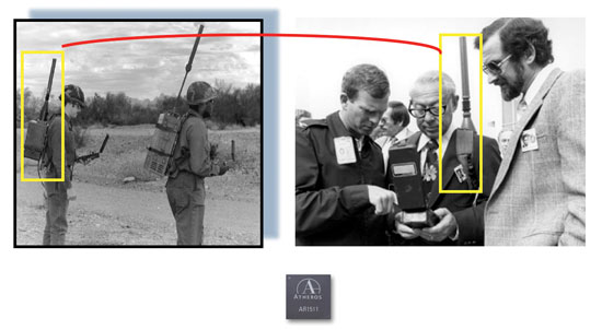
The single-channel manpacks were large and clumsy, but they operated very well. The payoff created by the CDMA signal is illustrated with the 12-channel, single-chip modern implementation, shown in the bottom picture. This contemporary chip’s accuracy is much better than any of the equipment produced during Phase I.
Developing test environment and analysis setup was almost as challenging as the user equipment. Lt. Col. Val Denninger, Maj. Darwin Abbey, and Lt. Cdr. Joe Strada led this very successful effort. While most testing took place at Yuma Proving Ground, test sites were also located in San Diego and elsewhere.
Left: 1978 single-channel (sequential) Manpacks, two types by Magnavox and Texas instruments. Batteries alone weighed much more than current military handsets. Right: The second JPO deputy, Col. Don Henderson (left), and Aerospace program manger Ed Lassiter (right). Bottom: A modern 12-channel (parallel) Atheros chip receiver with more capability. (Credit: Bradford W. Parkinson and Stephen T. Powers)
The Most Fundamental GPS Innovation
The CDMA (spread-spectrum or PRN) modulation used for passive ranging is clearly the most fundamental innovation of GPS. This signal enabled four-dimensional positioning for the user without requiring an atomic clock in the user equipment. The Russian GLONASS (the other, partially-operational global navigation satellite system) also used spread-spectrum passive ranging, but resorted to a frequency-separation scheme (FDMA, frequency-division multiple-access) that has proven inferior in actual use.
The innovative design of this CDMA signal has enabled all of today’s precision applications for GPS. It is currently common for inexpensive GPS receivers to simultaneously receive signals from more than 10 satellites, yet all of these signals are being broadcast on exactly the same frequency. In fact, the number of signals that can be received is virtually unlimited using the spread-spectrum CDMA approach. Using a routine processing algorithm, the user, receiving more than four signals, has an instantaneous position that is more accurate than that using four satellites alone. This robustness includes a technique to ensure integrity of the GPS solution. The method, called receiver-autonomous integrity monitoring (RAIM), isolates a rogue satellite that is not operating properly, to ensure integrity of the GPS solution.
Another technique, called carrier tracking, is enabled with the coherence of the code and the carrier broadcast in this signal. When coupled with some form of differential GPS operation, the result is relative positioning accuracy that is unprecedented — frequently better than a millimeter. For example, surveyors can now routinely resolve three-dimensional position to this accuracy. Even common user equipment can make use of the coherence of the signal. The receiver accomplishes this by employing the so-called Hatch/Eschenbach filter that uses the reconstructed carrier signal to smooth the code-transition measurement that greatly decreases the noise of the raw code measurement.
The processing gain in the GPS CDMA signal has been enhanced by deep integration with inertial navigation components. This has enabled the demonstrations of very high interference rejection by such receivers. DaleKlein and Ed Copps of Intermetrics Corp. were major contributor
s to the integration of GPS with inertial measurement units for the Magnavox high-performance military receivers.
Side-Tone Ranging. The competing side-tone ranging signal structure offered by NRL in the 1970 Easton patent had a fundamental flaw. If the signals were broadcast at the same frequency, they would interfere with each other. On the other hand, if they were broadcast on different frequencies, the user equipment would require a separate analog front end and tracking loops for each signal. In addition, each channel would have its own time-delay bias that would probably vary with temperature of the user equipment. A study by Magnavox also noted that the side-tone ranging signal could be easily spoofed; it was not clear how to encrypt such a signal. The final problem was that the signal was fundamentally an analog type and would have not been able to take advantage of modern digital signal processing. As a result, the receivers would be more complex and expensive.
The Air Force 621B/Aerospace and Magnavox studied the CDMA signal structure extensively after the 621B Woodford/Nakamura study was completed in 1966. Bob Gold of Magnavox had, in 1967, invented the technique to select acquisition codes that were mathematically guaranteed to not look alike (were uncorrelated). Early in the program, the JPO hired Dr. Jim Spilker, a recognized worldwide authority on digital signal processing, to contribute to this effort. Another worldwide expert, Charlie Cahn of Magnavox, was also a major contributor to the signal design. As mentioned previously, the details of the signal required the efforts of many people.
By 1969, the CDMA signal was being used in many communication applications. Adapting this signal for navigation raised the questions that were posed in an earlier section. It is hard to believe today the issues surrounding its use had to be addressed in 1970. It is to the great credit of Program 621B that it built the receivers and ran the series of tests at White Sands Missile Range that had earlier resolved all the major issues surrounding the signal structure. This irrefutable evidence allowed the JPO team to confidently choose this signal during the Lonely Halls meeting in September 1973. Great credit must go to Bill Feess who worked tirelessly to complete the analysis that demonstrated 5-meter accuracy in those White Sands tests.
CDMA-Enabled Applications
The distinction between the Timation side-tone ranging and the 621B CDMA signal is critical to understanding the origins of GPS. The Air Force CDMA signal was different in essential and fundamental ways from the Easton side-tone ranging modulation. Three examples of precise three-dimensional applications, not achievable with side-tone ranging, illustrate the subsequent success of the 621B digital CDMA signal.
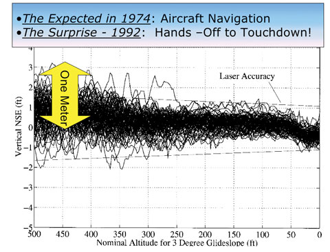
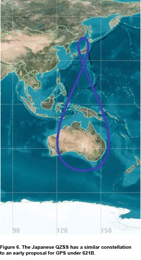
Aircraft Blind Landing. In 1992, the Federal Aviation Administration (FAA) sponsored Stanford’s development and demonstration of the first Category III (blind landing) system in a commercial aircraft; the effort was led by Clark Cohen and developed by a group of Stanford students under the supervision of Brad Parkinson. The only sensor for both position and attitude was GPS. The carrier-tracking receiver was a derivative of a Trimble receiver; it relied on the CDMA signal structure for both accuracy and integrity. (See Figure 6.)
Figure 6. Results of first blind landing tests using GPS alone, 110 landings with a commercial Boeing 737. (Credit: Bradford W. Parkinson and Stephen T. Powers)
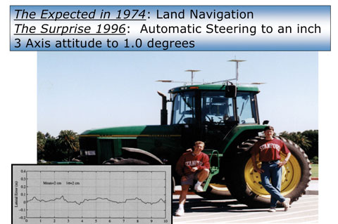
Robotic Farm Tractor. Using similar technology, a different group of Stanford students in the same lab demonstrated the first precision GPS-controlled robotic farm tracker. Again, the capability was enabled by the GPS CDMA signal. The John Deere Company sponsored this effort, which has now expanded into a worldwide market of more than $400 million per year.
Robotic farm tractor developed at Stanford with support from John Deere company. Student leader Mike O’Connor and colleague Tom BeLl shown. Tracking test at 5 meters/second, with worst error around 3 inches! Now a $400M/year market. (Credit: Bradford W. Parkinson and Stephen T. Powers)
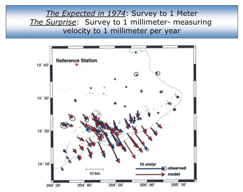
Earth Crustal Monitoring. A third example of the power of the CDMA signal is precise survey, focused on Earth movement and crustal tracking (Figure 7). The original GPS surveying receivers were pioneered by PhilWard at Texas Instruments and Charlie Trimble at Trimble Navigation, among others.
Figure 7. Continuous observation of earth crustal motion with a precision of better than a millimeter: distributed slip on Kilauea volcano, Hawaii. (Credit: Bradford W. Parkinson and Stephen T. Powers)
Summary. Many technologies came together to make GPS operational, none more revolutionary than the signal structure demonstrated by 621B at White Sands, and selected by Parkinson during the Lonely Halls meeting. Virtually all high-precision uses of GPS depend on the characteristics of this signal.
Credit: Bradford W. Parkinson and Stephen T. Powers
More on GPS Origins
The fundamental basis for the GPS design was clearly the Woodford/Nakamura and subsequent studies undertaken by 621B, not the system outlined by NRL in the Easton patent. More than 500 million current users have overwhelmingly confirmed the value of the selected technique using a minimum of four-satellite passive ranges and the CDMA signal. If each GPS user had to employ an atomic clock, the price of most GPS receivers would be prohibitive. The value of a four-dimensional solution for users has also been irrefutable. Had GPS followed the blueprint of the NRL patent, it is reasonable to say that almost all system uses, military as well as civilian, would have been fatally compromised. Further, had the Easton side-tone ranging signal been selected, broadcasting 30 satellites on the same frequency, as GPS does today, would have created an undecipherable electromagnetic jumble.
Summarizing Easton’s Patent. We earlier mentioned the NRL/Easton patent for the Timation design. It is important to summarize that invention and its relationship to the actual GPS design. A few people have written that Roger Easton “invented” GPS. As stated, Easton did have a competing concept that he had developed at NRL. In October 1970, four years after the completion of the secret, seminal system study by Woodford and Nakamura, Easton applied for a patent, “Navigation System Using Satellites and Passive Ranging Techniques,” that was granted on January 29, 1974 (U.S. 3,789,409). A careful reading of the patent, available on the web, reveals the following:
The technique described by Easton clearly calls for a synchronized “extremely stable oscillator” at the user station. Elsewhere he states: “would typically be controlled by an atomic clock.” This less-capable method of navigating was examined in the Woodford/Nakamura study, four years before Easton’s patent application, and is definitely not the technique chosen by GPS.
The patent advocates the use of a passive ranging technique, whose description occupies most of the patent, with multiple frequency tones, not the CDMA technique of GPS that had already been studied by 621B. Before the patent was issued, 621B had already built prototype GPS CDMA receivers, flown them at the White Sands range, and demonstrated three-dimensional accuracies of about 5 meters. The Easton passive-ranging technique, commonly called side-tone ranging (STR), had been included in a 621B analysis of alternatives. STR was rejected because of poor resistance to interference or spoofing, and the inab
ility to broadcast all satellites at the same frequency without destructive self-interference.
Both the description and the accompanying diagram in the patent clearly refer to two-dimensional navigation, using lines of position. To extend this to three or four dimensions was not mentioned. Such extension would probably only be possible if the satellites all broadcast on different frequencies, which would have made extremely high-precision positioning (as attained by the actual GPS design) infeasible.
Thus, it is correct to state that the Easton patent did not, in any way, represent the actual GPS design in at least these three fundamental aspects.
Further Transit Contribution. In 1974, after the first phase of GPS had been approved, the Transit program requested funds to upgrade the Transit signal structure to the same passive ranging technique (CDMA) being planned for GPS. The program’s purpose was to use Transit signals to track Trident missile testing launches in broad ocean areas. Air Force Col. Bradford Parkinson (director of the GPS Program), Dr. James Spilker (Stanford Telecommunications Inc.), and Jack Klobuchar (Air Force Cambridge Research Laboratory) responded with a technique for substituting GPS signals, with a translated frequency relayed to the ground to track those missile tests.
After three Pentagon briefings on the proposed alternative technique, Dr. Bob Cooper of the DoD concluded that the GPS signal would be used. Included was a decision to add two more satellites to the Phase I development of GPS to accommodate the Trident launch window. As a result, $66 million was transferred from the Navy to the USAF GPS program. The benefit to the fledgling GPS program was enormous. This greatly expanded the test time for GPS, and also reduced the risk, since no spare satellites had been approved for the program. While the Trident program was somewhat unhappy with the loss of funds and control, it immediately unleashed the creativity of Johns Hopkins University Applied Physics Laboratory and successfully met the Trident missile test tracking requirements.
GPS JPO Innovations
GPS was the first DoD program directed to be managed as a Joint Service Development Program. This new approach, conceived by Dr. Currie, led the GPS program to be designated a JPO or Joint Program Office. As a result, there were deputy program managers assigned from the Navy (Cdr. Bill Huston), Army (Lt. Col. Paul Weber), Marine Corps (Lt. Col. Jack Barry), and Defense Mapping Agency (Paul Frey), as well as the customary Air Force deputy (initially Lt. Col. Steve Gilbert, later Lt. Col. Don Henderson). Rather than use these well-qualified people from other services simply as liaisons, they were each assigned specific programmatic responsibilities.
At the first major program review at Andrews Air Force Base, Parkinson called the convening general’s attention to the fact that he was leading a joint program, and with the general’s indulgence he had invited his deputies from the other services to attend. Since attendance by other services at Air Force program reviews was unheard of, this drew a gasp from the roughly 200 Air Force officers attending. The JPO approach truly broke new ground in intra-service cooperation.
At the JPO. Frank Butterfield of Aerospace, Col. Parkinson, and Cdr. Bill Huston, deputy JPO director from the U.S. Navy, in the early 1970s. A model of a Phase I GPS satellite stands on the table between the latter two. (Credit: Bradford W. Parkinson and Stephen T. Powers)
Parkinson had entreated the Federal Aviation Administration to also send a deputy. The public response by the FAA deputy administrator for development was: “We don’t want GPS, we don’t need GPS, and if it is ever deployed, we will never use it.” Throughout this period, Glen Gilbert (sometimes called “the father of air traffic control”) was a strong and early advocate for FAA use of GPS. It took many years for the FAA to accept his views. Obviously times change; the current relationship between the FAA and the GPS Program Office is excellent, fostered by Col. Dave Madden and his FAA counterpart Leo Eldredge.
JPO as Prime Contractor. The JPO cadre served as the prime or integrating activity for the whole program. Gen. Schultz almost fired Parkinson when he proposed this. The general had expected him to hire a separate commercial integrating contractor. After Parkinson explained that the major interfaces between the three segments — satellite, ground control, and user equipment — were the signals, Gen. Schultz acceded to the plan. This pioneering aspect was critical because it ensured that all aspects of the system would be under the direct purview and control of the JPO.
Award and Incentive Fees. The use of innovative procurement awards for the contractors was very new in DoD in 1974. Beginning with the satellite contract, the JPO made extensive use of new forms of positive rewards for the contractor, including incentives for on-orbit performance. Gaylord Green pioneered this activity with skills developed as a project officer in the Advanced Ballistic ReEntry Systems Program (ABRES) program office. Incentives were applied to virtually all the other contracts as well, and seemed to have a very positive effect.
Normally the Space and Missile Systems Organization (SAMSO) procurement office, which was independent of the JPO, would have been reluctant to approve such radical new ideas. Fortunately, Parkinson carpooled with another colonel who was head of SAMSO procurement and a breath of fresh air. This attitude was exemplified by a sign at eye level as you left the procurement director’s office: “Nothing would be done at all if a man waited until he could do it so well that no one could find fault with it.” (It turns out this came from remarks by Cardinal John Henry Newman.) With that attitude, the SAMSO office approved almost all of the JPO’s “wild” procurement innovations. Many of these innovations are now routine.
Changes. The Air Force provided a high-level spec for the satellite that defined the signal structure, the power on the ground, the frequencies, the orbit, and the amount of weight the booster could put into that orbit at apogee. The JPO left it up to the contractor to design a satellite that could meet those requirements. The key point is the JPO never changed the requirements, which kept GPS on course with minimum cost increases for the devlopment.
Refurbished Atlas F Booster. Today, up to half the cost of a satellite on-orbit is the cost of the booster to place it there. While the costs were perhaps not proportionally so large in 1977, they still could consume large pieces of a program’s budget. Luckily, the United States had mothballed much of its liquid-fuel ballistic missile force during that period. The JPO chose to use refurbished Atlas Fs as boosters, saving many millions of dollars. Some have suggested this idea originated with NRL. While NRL may have also been using them, both Parkinson and Green came from the ABRES program where refurbished Atlas Fs were already employed. Thus, the decision made in the Lonely Halls meeting was based on knowledge the JPO already had, which included additional steps the ABRES had taken to improve the reliability of the booster. (See Figure 8).
Figure 8. Refurbished Atlas-F booster characteristics. Col. Parkinson and Maj. Green brought this concept from previous use on the USAF ABRES program. (Credit: Bradford W. Parkinson and Stephen T. Powers)
A Motto. Emblazoned on a prominent wall in the JPO was a sign that read:
“The mission of this Program Office is to
Drop 5 bombs in the same hole
and build a cheap set that navigates
and don’t you forget it!”
By distilling the JPO mission into one succinct motto, the program intended to provide a guide for all its actions. If a decision fundamentally helped achieve that mission, it was probably the right one.
The Political Battlefield. Political battles in the Pentagon are often brutal and unforgiving. The fundamental reason is that the budget is always viewed as a zero-sum game. One program’s money comes at another program’s expense. GPS was a system that sprang from the space development community (“the Space Weenies”) and had virtually no champions from the operational components. Unlike current DoD satellite programs, there were no explicit formal requirements for the new system and hence little official status. Parkinson spent many trips to the operating forces to explain the value of precision weapon delivery. Between skepticism and deafness, GPS survival was always extremely uncertain. The Air Force generally opposed its deployment, even after the extensive tests of 1978–80 had clearly demonstrated that GPS was, by far, the best blind-bombing system ever conceived.
Fortunately, there were some key supporters of GPS who overcame that resistance. They were affectionately called the GPS Mafia. The most important member of this unchartered group was Malcolm Currie, whose efforts were discussed earlier. His powerful number-three position at the Pentagon gave him the authority to force funding decisions on the uniformed military. At least one general officer was extremely upset with Parkinson over his relationship with Dr. Currie, and gave him a public tongue-lashing over the issue during a chance encounter in a Pentagon corridor. Dr. Johnny Foster, whom Mal Currie replaced, was another early supporter of the program.
USAF Col. Steve Gilbert, the original deputy program manager for GPS in Los Angeles, was a tireless, heroic contributor. Later on he played a critical role, fighting the battles within the Pentagon as the Air Force Program Element Monitor (PEM). His next position was as the GPS representative in the Office of the Secretary of Defense. While there, Steve fought back repeated challenges that would have canceled GPS in the early 1980s. Without his efforts, GPS almost certainly would never have happened.
Other members of the GPS Mafia were Lt. Col. Paul Martin (the original GPS Program Element Monitor), Brig. Gen. Hank Stelling (RDS in Pentagon), and Cols. Brent Brentnall and Emmitt DeAvies (DDR&E representatives).
The users of GPS owe all of these supporters a real vote of thanks. As the Duke of Wellington said about the battle of Waterloo, “It was a near-run thing.”
Fortunately, GPS supporters prevailed, and the two Iraq wars have made all branches of the military believers in the value of the system, although they sometimes regard it as magic. A combat Army colonel in Iraq was reportedly asked what he thought of satellite systems to help him fight. His response:
“I don’t need any (expletive) space systems. My GPS and my Iridium comm give us everything we need.”
GPS really is a stealth utility.
Thoughts on the Future
There are now many additional or improved satellite systems on the horizon. American GPS has heretofore only offered a single, clear navigation signal for civil users. That is rapidly changing. Two more frequencies and a number of additional signals will be available from the next two generations of U.S. satellites. Other countries are also working hard to follow the GPS lead. Figure 9 depicts some of these new systems.
Figure 9. Upgrades of GPS (only current operational civil signal; next generation, four new civil signals at two new frequencies), GLONASS (next generation, four new civil signals at two new frequencies) and new international navigation satellite systems (Galileo, four new civil signals to appear at two new frequencies; finally, Compass) are on the near horizon. The plethora of signals will enable improved accuracy and integrity. This will lead to new applications. (Credit: Bradford W. Parkinson and Stephen T. Powers)
An international common navigation signal called L1C has been accepted and almost completely defined. It will broadcast on the same 1575 MHz frequency as the current GPS civil signal. It will be of the same type (CDMA) as the original GPS signal, although it will have significant enhancements to increase precision and accuracy. If the engineering is done properly, this signal should be interchangeable for all GNSS systems that support civilian use. The positioning, navigation, and timing (PNT) community will benefit enormously by having all of these signals available. Again, the key enabling decision was the CDMA signal structure defined by 621B and tested at White Sands.
We will mention one CDMA-enabled application with a large market potential. This is the use of multiple GNSSs (up to 50 satellites) in automobiles for lane guidance and car separation. During times of low visibility, freeways are notorious for multi-vehicle collisions. We believe the technology will be in hand to greatly reduce these tragedies. The new application would involve cooperative navigation with cars in the vicinity all tied together in a communication grid. GPS-measured velocity is almost a forgotten aspect of the system, yet it can be accurate to much better than 0.1 meters per second. If two cars in the vicinity of each other can know both relative position and relative velocity, collision probabilities can be easily assessed and avoidance actions quickly and automatically recommended.
This is just a glimpse of the future. We believe many other new or improved applications will be enabled by future deployments.
Summary
Just as a building is not invented, GPS was not the product of any single invention. GPS as a system was an innovation enabled by many antecedent technologies and concepts. Some were brand new in application, or had to be adapted to their role in GPS, for example the CDMA signal technique. In making those system selections, the final design was the product of the entire JPO team, whose roots went back to many of the greatest institutional sources of innovation in the country.
The two most critical foundations were:
The comprehensive study done by Jim Woodford and Hideyoshi Nakamura for USAF/621B in 1964/66, exploring virtually all alternative ranging techniques from satellites, both active and passive, and calling for atomic clocks in the satellites. In particular, the four-dimensional 621B concept of using “four in view” was analyzed and became the bedrock of the GPS design, ensuring that the user could make do with a simple crystal clock.
The selection and demonstration of the CDMA passive ranging signal by 621B at White Sands. These tests confirmed four-satellite, single-frequency operation and proved that such operation obviates the need for an atomic clock in each GPS user set.
These directly led to the systems architecture decisions made in the Lonely Halls meeting. Also essential were finding workable solutions to the five critical challenges:
Defining the specific details of the GPS CDMA signal structure
Achieving rapid and accurate satellite orbit prediction
Ensuring and demonstrating spacecraft longevity
Developing a full family of GPS user equipment.
In tracing the origins, the first navigation satellite program, the Transit program of APL, should be singled out. Working under contract to the Navy’s Nuclear Submarine Program, APL pioneered the dual-frequency technique to calibrate ionospheric delay errors as well as the painstaking development of an accurate orbit-prediction program. Both early efforts were essential to the ultimate success of GPS.
Also important was NRL’s push to harden frequency standards for use in satellites. While the JPO rejected Easton’s navigation technique, NRL’s apparent clock progress, by 1973, convinced the decisionmakers at the Lonely Halls meeting to commit to including atomic clocks in the first prototype, Rockwell-built GPS satellites. While it is ironic that no clock with NRL heritage was operational on the first four GPS satellites, the NRL’s persistence finally paid off with the introduction of its cesium beam clocks on an equal footing with the Efratom/Rockwell-designed rubidium clocks later, during GPS Phase II.
Throughout this article, many of the contributors to the early definition, development, and testing of GPS have been named. Certainly many others have also been inadvertently left out. In closing we would like to sincerely thank the scores of engineers who assembled the first-of-a-kind demonstration system.
As a stealth utility, one pervasive accolade is that GPS is now taken for granted. People throughout the world now expect to know exactly where they are and what time it is.
This month’s professional OEM newsletter by Rob Lorimer is about the use of GPS and other positioning technologies in open-pit mining and compliments a GPS World webinar on this subject scheduled for 1 p.m. PST May 20. The article also appeared in the August 2010 issue of GPS World magazine with a sidebar by Geoff Roberts of Leica Geosystems (see below).
By Rob Lorimer
Open-pit mining (also called open-cut, open-cast, and strip mining) has historically been an early and innovative adopter of new positioning technologies. Some of the earliest examples of fitting GPS to heavy earth-moving machinery occurred in the U.S., Australian, and Canadian mining industries in the 1990s. Miners were also quick to adopt the first GPS/GLONASS systems. The trend continues today with trials of new radio positioning technologies such as the Novariant Terralite XPS and the Locata system.
Phase 2 of a global mining boom is underway, driven by an apparently insatiable appetite for primary resources from developing economies such as China and India. Indeed, according to one study by Access Economics, to meet projected demand the production of some commodities such as nickel and zinc will need to double in the period 2000-2020; others, including coal and iron ore, will need to increase by 40-60% over the same period.
The response from the mining industry is two-fold. First, increase the productivity of existing mines; second, explore and develop new mining territories. Both these responses increase the demand for positioning systems, but we will focus here on first response.
Increased Productivity. Increasing the productivity of existing mines can take several forms, including extending the life of the mine and extracting the commodity more effectively. The former is generally driven by higher commodity prices (previously marginal deposits become viable); the latter is driven by adopting improved practices and new technologies, including those incorporating positioning components.
Productivity gains from new technology are multiplied by the scale of the mining operation, so it is no surprise that the largest mines were the first to experiment with and adopt new position-based systems, particularly in earth moving and commodity handling. The scope for productivity improvement is huge — there are more than 100 open-pit mines that move more than 1 million tonnes of material per week, about half of which are in Australia, Canada, and the U.S. Another 600-700 open-pit mines worldwide move between 10-50 million tonnes/annum, and a further 1,500 or so move 1-10 million tonnes/annum. On top of these there are tens of thousands of smaller mines and quarries, although to date most of these do not use innovative practices or technologies.
Just as new practices were usually adopted first in the super-mines and then progressivity smaller operations, there was a similar trend to apply new positioning-based solutions first to the largest earth-moving machines and then to progressively smaller machines and vehicles. As this process unfolded during the 1990s and 2000s, a number of companies emerged as global technology suppliers for mining, including the Caterpillar/Trimble Joint venture, Modular Mining (owned by Komatsu), and Leica Geosystems. However, there remains a vibrant small- to medium-enterprise (SME) positioning-based solutions sector in mining, most of which is focused on technology niches (for example, Novariant, APS, and Accumine.
Collision Avoidance. As positioning-based solutions progressively made their way onto heavy machinery (such as draglines, excavators, and dozers), and haul trucks and auxiliary equipment (drills and explosives trucks) for production purposes, another set of suppliers were eying up positioning technologies for a different reason.
As mines increase production from existing operations, site traffic increases and so does the risk of collisions. Of particular concern are collisions between heavy and light vehicles, which have a high probability of serious injury or fatality. There are many safety issues to be addressed: mining machinery and haul trucks have extensive operator blind spots, haul roads are unsealed and need constant maintenance, blind corners are common and intersections change frequently. Add to these issues 24-hour working, driver fatigue, frequent poor visibility caused by dust or snow, and the requirements for safety systems becomes apparent. The second wave of suppliers adopted GPS, RFID, lasers, radar, and other technologies to develop a range of driver adherence, situational awareness, proximity detection, and collision avoidance systems. These companies include Caterpillar, SafeMine, AMT, 3DP, and others (see the Professional OEM newsletter from July 2009 for a fuller discussion on GPS-based safety systems in mining).
When we add together the positioning requirements for both production and safety systems, we start to get a feel for the variety of positioning solutions applied on large open-pit mines today as illustrated by the table below. Indeed, on some of the most advanced mines virtually everything that moves, or can be moved, is fitted with some sort of positioning device for production, operational, logistics, or safety reasons.
TABLE 1. Positioning options for open-pit mining. GPS remains a popular choice.
As the table illustrates, despite its limitations in deep open-pit mines, GPS remains a popular choice for positioning and can be found on most platforms from people to heavy machinery. GPS/GLONASS (GNSS) receivers have largely replaced GPS-only receivers for heavy machinery, haul trucks, and auxiliary equipment (such as drills) as it delivers improved availability over GPS. However, the cost of GNSS receivers has meant they are not as popular on the more numerous light vehicle fleets. With low-cost GNSS chipsets coming on the market, we can expect this situation to change quickly over the coming years.
Both high-end (HI Inertial) and low-cost (LO Inertial) technology are deployed in open-pit mining, usually in conjunction with GPS or GNSS. High-end inertial systems tend to be in machine control systems; the low-cost devices, including electromagnetic compasses and accelerometers, are more often used in vehicle and personal safety devices.
In the table above, I have distinguished between radio positioning and radio location technologies. The former are dedicated positioning systems such as the Novariant Terralite and Locata, which deliver precise positioning from planned networks of transponders on site. The latter derive location from communications systems, and are generally accurate to a few meters (for example, the 3DP systems built on a Motorola Motomesh backbone).
Radio Frequency Identification (RFID) location is well established in the mining industry for both underground and open-pit operations. Although not used for high-precision machine control applications, RFID can be found on all platform classes for safety, operational, and logistics purposes.
Both Electronic Distance Measuring (EDM) and laser technology are used to position machines and haul trucks. As these are line-of-sight systems, they tend to be deployed in close proximity to work areas. Laser technology is used with roadside beacons to locate and navigate trucks along haul roads.
Finally, radar is used in several safety systems for proximity detection and collision avoidance, but can also be used with roadside beacons for navigation and location.
Positioning Mix. The reali
ty is no single technology has the right mix of precision, availability, and cost to meet all the production, operational, logistical, and safety applications within open-pit mining today. System integrators are experimenting with different combinations, with many claims and counter claims about which mix is superior. What may well be a deciding factor for success is which positioning technologies (or technology combinations) are scalable to non-mining applications; that’s where GPS, GNSS, and RFID have a distinct advantage today.
A deeply cut open-pit mine. (Image courtesy of Brendon Lilly.)
Digging for Accuracy
By Geoff Roberts, Leica Geosystems
A reality of open-pit mining is the challenge of GPS positioning coverage as the mine is cut deeper into the earth, and with the price of minerals rising, miners are digging deeper than ever before. Reduced sky view to satellites, especially where machinery is working near pit walls, can cause signals to become obstructed. With high-precision machine-control systems heavily utilized on mining equipment, a loss of positioning signal affects mine productivity. For years, Leica Geosystems has addressed sky-view issues by offering hybrid positioning for its high-precision mining machine control systems, using GPS and GNSS signals. While this has seen great advantages, GPS and GNSS share the same weakness as the pit is cut deeper or when operating against a high wall.
Recent developments aimed at making systems less dependent on satellite signals has resulted in the successful integration of a “local positioning constellation,” through technology developed by Locata Corporation. LocataLites are positioned around the rim of the pit and transmit to machinery-mounted receivers integrated into Leica Geosystems’ high-precision machine-control system, acting as local satellites with the advantage of being visible to machine-control systems, independent of GPS/GNSS coverage.
With this integration, blast-hole drills, dozers, and shovels can continue operating to centimeter accuracy when GPS/GNSS is unavailable. LocataLites self survey using GPS at the surface level where coverage is trouble free, and can easily be moved around a site to cover holes in coverage. Locata positioning becomes more accurate as the pit is dug deeper due to gaining sufficient vertical geometry for 3D positioning, a great advantage as the pit grows down. Rigorous testing of Leica Geosystems’ Locata integrated system has been conducted at one of Australia’s largest mines over the last six months. Results have proven reliable and accurate, while delivering significant productivity gains through reduced downtime caused by GPS/GNSS coverage holes.
By Brady O’Hanlon, Mark L. Psiaki, Paul M. Kintner Jr., and Steven P. Powell
Anomalous behavior of the L1 C/A-code carrier phase has been detected on PRN07/SVN-48. The anomalies are sudden step-like changes of phase by about 10 degrees/5 millimeters. These steps are followed by negative steps of the same magnitude that restore the original phase time history. These anomalous square pulses have been observed with durations as short as 0.1 seconds and as long as 600 seconds. They can occur about once a minute or be absent for hours.
These anomalies could be of consequence for some GNSS applications. For precise monitoring of differential total electron content (TEC), the magnitude of this anomaly is the same order as the signals of interest. Precise point positioning (PPP) systems seek to achieve CDGPS accuracy without direct double-differencing. The lack of double-differencing would allow any L1 C/A carrier phase anomaly to directly affect the PPP solution.
This behavior was detected when testing a dual-frequency software receiver that processes the GPS civilian signals on L1 and L2. The anomaly was first noted when calculating carrier-phase-based TEC:
where bTEC is a bias term that occurs in the phase-based calculation. Figure 1 shows a plot of the resulting TEC, after removal of its mean value, with six square-edged pulses that range in duration from 0.1 to 590 seconds, with the first a short one at t = 48 seconds. The last pulse starts at 710 seconds and ends at 1300 seconds. In all cases, the anomaly consists of a positive step change in TEC followed some time later by a negative step change of identical magnitude. Step magnitudes in the range 0.04 to 0.07 TEC units have been observed.
Figure 1. Square pulses on phase-based TEC due to L1 C/A carrier phase anomalies.
Tests were performed to ascertain whether the anomalies were caused by the L1 signal, the L2 signal, or a combination of the two. Additional tests ruled out receiver malfunction as the cause of the anomalies.
Observation of detrended L1 and L2 carrier-phase time histories quickly revealed that the anomalies occur on the L1 carrier phase. The detrended L1 C/A carrier phase shows square-edged pulses corresponding to times, magnitudes, and signs of the TEC anomalies, but the detrended L2C carrier-phase plots show no such pulses. Figure 2 shows a typical detrended L1 C/A beat carrier-phase anomaly.
Figure 2. A typical detrended L1 C/A beat carrier-phase anomaly.
Extensive tests checked whether the anomalies may have been caused by the receiver. They were initially discovered using a digital storage receiver of raw RF front-end samples followed by off-line software receiver processing. Such carrier-phase anomalies could result from signal glitches in the RF front-end’s mixing chain, from data recording anomalies in the RF front-end samples, or from errors in the software receiver code. The former two possibilities were ruled out by two means. One was to process signals from other satellites for the same RF samples. Mixing problems or data sample problems would cause similar anomalies on all GPS signals, but other GPS signals were found to be free of anomalies. Additional tests used simultaneous data collection by two digital storage receivers spaced 700 meters apart and using different RF front-end hardware. Both receivers showed identical anomalies at identical times.
Software receiver code errors were ruled out by employing two independent sets of receiver processing code, one developed in MATLAB, the other in C. These two pieces of software were developed independently by different individuals and run independently by their developers. Both showed identical anomalies.
A final check used a different receiver, the NovAtel GSV4004B. Figure 2 plots its detrended L1 C/A carrier phase along with that of the C-based Cornell software receiver. Both show the same anomaly. Thus, the anomalies appear to be caused by the SVN-48 transmitter.
All observations were made from roof-mounted antennas in Ithaca, New York. The anomalies were first observed on March 24, 2010 and were observed again on April 1, 5, 7, and 29, and as late as May 13th. For one period of several hours on May 11, no anomalies occurred. Other Block IIR-M satellites have been monitored briefly, but without finding any similar anomalies to date: SVNs 58, 55, 57, 49, and 50.
INRIX announced its Smart Driver Network has grown to more than 2 million GPS-enabled vehicles giving drivers a reliable, real-time view of traffic conditions on more than 260,000 miles of highways, city streets and secondary roads nationwide.
“Our Smart Driver Network is the largest real-time traffic network in the world. It redefines what it means to deliver truly real-time traffic information,” said INRIX President and CEO Bryan Mistele.
According to the announcement, more than 40 percent of all State DOTs in the United States rely on INRIX’s real-time traffic information for their daily operations, traveler information services and/or congestion performance measures. New projects in 2010 in 5 states – Texas, Massachusetts, Maryland, Minnesota and Ohio – are using INRIX traffic data and travel times for their planning efforts, statewide 511 systems or dynamic message signs.
“In just two years, INRIX has grown from providing traffic data for one state agency to powering the daily operations, planning or traveler information services in 21 states and the District of Columbia,” said INRIX Vice President of Public Sector Rick Schuman.
By Bradford W. Parkinson and Stephen T. Powers, with Gaylord Green, Hugo Fruehauf, Brock Strom, Steve Gilbert, Walt Melton, Bill Huston, Ed Martin, James Spilker, Fran Natali, Joe Strada, Burt Glazer, Dick Schwartz, Tom Stansell, and others
The original system study, the key innovations, and the forgotten heroes of the world’s first — and still greatest — global navigation satellite system. True history, told by the people who made it. Part One of a Two-Part Special Feature.
The stealth utility: over the past 30 years, a new entity has steadily and stealthily crept into the fabric of worldwide society, creating capabilities and dependencies that did not exist before. This utility is known as the Global Positioning System, or GPS. With more than a billion GPS receivers in use, this stunning achievement has truly revolutionized the way the world functions in the 21st century. Virtually every cell-phone system relies on GPS for timing. Almost every ship and aircraft carries multiple GPS receivers to provide positioning information. Other applications span military targeting, transportation, object tracking, and resource identification. Today, the loss of GPS signals would have catastrophic consequences.
How did GPS come into being? What technologies were essential to its success? Who developed those technologies? Recently a number of GPS histories have appeared that are very inaccurate on these subjects. Our purpose in writing this account is to set the record straight, and in so doing to give credit to many of the original developers of GPS whose contributions have somehow been forgotten. Throughout this article you will find their names highlighted. Space does not permit us to name the many other individuals who deserve enormous credit for the subsequent refinement and invention of new GPS applications.
Figure 1 gives a summary view of the history of U.S. satellite-based navigation, particularly GPS. Details of the Russian GLONASS and the European Galileo systems are not included as they arrived later, and generally mimicked the GPS development albeit with their own, locally developed detailed designs.
Figure 1. The eras of satellite navigation. (Credit: Bradford W. Parkinson and Stephen T. Powers)Dr. Richard Kershner, who led the development of Transit. On his left, young Col. Bradford Parkinson, who led the development of GPS. (Credit: Bradford W. Parkinson and Stephen T. Powers)
This history focuses on the period up to about 1980, when GPS was approved for full-scale development. Between that time and the date that GPS was declared fully operational, April 27, 1995, many additional contributions were made. The system withstood several early attempts by the Air Force to cancel it entirely. Fortunately, those attempts did not succeed, and the Air Force now fully embraces GPS as an essential part of virtually every weapon system in the inventory.
We call this a tribute to the almost-forgotten people whose intellectual labor and skill initially developed GPS. As we unveil this story, we will point out the original — and critical — system study, the 1966 Woodford/Nakamura Report, that became the essential blueprint for GPS. Many people are unaware of this study since, in its original form, it was classified U.S. Department of Defense (DoD) Secret. It was not declassified until August 1979, more than a year after the first launch of a GPS operational satellite in February 1978.
We also intend to describe and justify the key innovation that enabled the system. This keystone technology is the GPS code-division multiple-access (CDMA) signal. While CDMA was necessary for GPS success, it was by no means sufficient.
We will also define and describe the five major original challenges that had to be met to achieve the success that GPS now enjoys; that will come in the second installment of this history, to appear in next month’s issue.
Mathematician Bill Guier (l) and physicist George Weiffenbach (r), told APL Research Center director Frank T. McClure (c), about their success using Doppler tracking for satellites. “McClure’s brain started going into fast forward,” remembered John Dassoulas. “Knowing the navigational challenges the U.S. Navy faced, McClure said, ‘Well, if you can find out where the satellite is, you ought to be able to turn that problem upside down and find out where you are.’” (Credit: Bradford W. Parkinson and Stephen T. Powers)
GPS Predecessors: Transit
On October 4, 1957, the entire world was amazed by the launch of Russia’s Sputnik satellite. The American public greeted this event with both apprehension and curiosity. Both the Army and Navy had been quietly working on satellite projects for some years. In an attempt to catch up, the United States had a spectacular failed launch when the Naval Research Laboratory’s (NRL’s) TV-3 crashed on December 6, 1957. On January 31, 1958, the United States Army launched a grapefruit-sized satellite, Explorer 1. The NRL then achieved success with the launch of TV-4, renamed Vanguard-1, on March 27, 1958.
In 1958, the Applied Physics Laboratory (APL) of Johns Hopkins University employed an extremely competent team of engineers and scientists. Two of those scientists, Drs. William Guier and GeorgeWeiffenbach, began to study the orbits of the new Sputnik satellites. The satellites were broadcasting a continuous tone signal. Their velocity relative to the ground created a Doppler shift of that signal that was unique. After some innovative work, Guier and Weiffenbach discovered they could determine the Sputnik’s orbit with a single pass of the vehicle.
At that point Frank McClure of APL made a very creative suggestion: Why not turn the problem upside down? Using a known satellite position, a navigator could determine his location anywhere in the world after receiving and processing the satellite signal for 15 minutes. His insight became the basis for the Navy’s Transit satellite program, also known as the Navy Navigation Satellite System (Figure 2).
This pioneering system was developed under the leadership of Dr. Dick Kershner, head of the Space Department of APL. Transit’s main purpose was to provide position updates to the United States submarine ballistic-missile force then under development. These submarines were a major deterrent during the Cold War. Transit was first tested in 1960, and by 1964 the system was fully operational. Under Kershner, APL rapidly mastered the art of building long-life satellites. In fact, two of the vehicles continued operation for more than 20 years.
Figure 2. The Transit birdcage of operational orbits. (Credit: Bradford W. Parkinson and Stephen T. Powers)
Transit was a relatively small satellite that initially used solar power and gravity-gradient stabilization (Figure 3). It provided a position fix every few hours; fixes took 10 to 16 minutes of exposure of the submarine’s antenna on the surface. It achieved 25-meter accuracy, but only in two dimensions. Further, if the user was moving, accurate velocity measurement was critical: a 1-knot error would produce a 0.2-nautical mile position error.
All Navy ships could use the system, and in 1967 Transit was offered to the civilian community by Vice President Hubert Humphrey. Magnavox became the principal developer of civil user sets with Tom Stansell as an early expert in the technology.
Contributions to GPS. The Transit program developed a technique essential for GPS: the use of two frequencies to calibrate the time delay of the radio signal induced by the ionosphere. This dual-frequency technique was incorporated into GPS to attain the highest positioning accuracy. In addition, Transit also pio
neered the accurate prediction of satellite orbits, another essential GPS technology. Orbit prediction will be highlighted later, as one of the five fundamental challenges that faced GPS system designers.
In 1974, Transit made a further contribution to GPS development that we discuss in that approximate timeframe.
Figure 3. A Transit satellite showing the gravity-gradient boom that kept the antennas pointing at the earth. (Credit: Bradford W. Parkinson and Stephen T. Powers):
Program 621B
As early as 1962, Dr. Ivan Getting, president of the Aerospace Corporation, saw the need for a new satellite-based navigation system. He envisioned a more accurate positioning system that would be available in three dimensions, 24 hours a day, seven days a week. He had direct access to the highest levels of the Pentagon and was a tireless advocate for his vision.
Getting’s energy and foresight in the early 1960s were essential to gaining Air Force support to study system alternatives. As a result, the Air Force formed a new satellite navigation program that was later named 621B. Getting’s efforts were recognized in 2002 when he shared the Charles Stark Draper Prize of the National Academy of Engineering with Bradford Parkinson.
By 1962, engineers at Aerospace, under Air Force sponsorship, were heavily immersed in studying the system aspects of a new navigational satellite system. From 1964 to 1966, Aerospace carried out an extensive, formal system study whose principal authors were James Woodford and HideyoshiNakamura, both highly regarded space-systems engineers.
Their work was summarized as a DoD secret briefing in August 1966. As a result of the classification, it was unavailable to anyone outside the project until 13 years later, in 1979, when it was finally declassified (figure 4).
The Woodford/Nakamura Report was a complete system study that examined these issues:
capabilities and limitations of then-current DoD navigation systems;
tactical applications and utility of improved positioning accuracy;
comprehensive analysis of alternative system configurations and techniques for positioning, using satellites.
The report concluded with a set of recommendations for advanced technology development for navigation satellite programs.
Figure 4. Front page of the seminal GPS system study performed from 1964 to 1966 by USAF 621B Program. Originally classified secret, it was not declassified until after the initial GPS satellite had been launched. This was the essential foundation to the GPS System design. (Credit: Bradford W. Parkinson and Stephen T. Powers)
The detailed analysis of possible passive navigation techniques was extremely important. It pointed out that the most capable passive-ranging design, called triple delta rho, would eliminate the need for an extremely stable clock in the user equipment and would provide three-dimensional positioning. (In this article we use clock, oscillator, and frequency standard interchangeably. The timing community makes some distinctions among these words, but for purposes of this history the distinctions are not particularly important.) This later was selected as the fundamental GPS system concept of ranging to four satellites simultaneously.
Key conclusions of the 1966 study advocated:
passive ranging from the satellites (the issue was which ranging signal to use)
atomic clocks in space, and a technology program to develop space hardened atomic clocks
further system studies as well as experimental demonstrations.
Since the full survey of alternative system configurations was extremely important in selecting an optimum system configuration, we reproduce the summary in figure 5. Note that the “Computation Performed by User” is split into two columns. Focus on the columns of the one-way passive ranging techniques with the red outline. Inside, there are two “user boxes,” one with A and one with X. The A shows the user needs an atomic clock. The X shows the user needs only a crystal clock. The option later selected for GPS is designated as G. This technique is the 3Δρ (triple delta rho, or four satellites) that eliminated the need for the user atomic clock, and provided three-dimensional positioning (really four-dimensional since it also captured time).
In October 1970, more than four years after the completion of this study, Roger Easton of NRL applied for a patent on the two-satellite, ρ-ρ technique (option N) that required an atomic clock for the user and was only two-dimensional. The patent (U.S. 3,789,409) was granted in 1974, a year after the three-dimensional design of the GPS system had already been defined in the Lonely Halls Pentagon meeting to be described later.
Figure 5. Summary of the alternative satellite-based navigation techniques from the1964–66 USAF/621B study. The most capable option, circled in green, became the basis for the White Sands prototyping and testing, and then evolved into GPS. NRL applied for a patent on the less capable technique (red line) four years after the Woodford/Nakamura Study was completed. (Credit: Bradford W. Parkinson and Stephen T. Powers)Credit: Bradford W. Parkinson and Stephen T. Powers
More 621B Studies. From 1966 to 1972, program 621B continued with trade-off studies including: signal modulation, user data processing techniques, orbital configuration, orbital prediction, receiver accuracy, error analysis, system cost, and comprehensive estimates of the tactical mission benefits. More than 90 reports completed by USAF/Aerospace during this period remain available in the Aerospace Corporation library.
PRN or CDMA Signal Structure. Of these studies, the most important were those aimed at selecting the best passive ranging technique for the navigation signal. By 1967, it appeared that the best technique was a variation of a new communications modulation known as CDMA. Pioneering this signal were several outstanding scientists, Dr. Fran Natali and Dr. Jim Spilker (both of Philco-Ford), and Dr. Charlie Cahn (of Magnavox).
Credit: Bradford W. Parkinson and Stephen T. Powers
This signal has many names. In addition to CDMA, it is sometimes called spread spectrum, since the energy of the signal was spread over a wide range of radio frequencies. It is also sometimes called PRN or pseudorandom noise because the encoded (and repeated) sequence appears to be random transitions of +1 and -1.
The name code-division is used because each satellite is assigned its own coded signal. Each was a binary (digital) sequence selected to be uncorrelated with other signals and also uncorrelated with time shifts of the signal itself. The expected, powerful advantage of this technique was that all satellites would broadcast on exactly the same frequency. It would clearly lend itself to digital signal processing. Furthermore, and very important, any time-shifts induced by the receiver for the various satellite signals would be effectively eliminated.
However, several significant questions concerning CDMA still needed resolution. These included:
Could such a signal be easily acquired in the face of time uncertainty and Doppler shifts?
Was there a technique to encrypt the military signal so that unauthorized users could not gain access?
How would the c
odes be easily selected to avoid a false lock and also allow additional satellites to be added without interfering with existing satellite signals?
Would the anticipated complexity of the receiver drive costs to unacceptable levels?
Was the signal resistant to accidental or deliberate interference?
Could this signal accommodate communication capability for satellite location, satellite clock correction, and other parameters?
Fortunately, in 1967 a technique for selecting orthogonal codes was invented by an accomplished applied mathematician, Dr. Robert Gold of the Magnavox Corp. Naturally these are now known as the Gold codes. His solution resolved the third CDMA issue stated above.
White Sands Tests. To address the remaining issues, the 621B program developed two prototype versions of CDMA navigation receivers (Magnavox and Hazeltine) for testing at the White Sands Missile Range (WSMR). For these initial 1971 tests, 621B arranged four transmitters in a configuration known as the inverted range. (Interestingly, the more capable receiver was the MX-450 that was only on loan from Magnavox.) These transmitters broadcast CDMA signals from locations that were similar to a satellite configuration except that they were broadcast from the ground. For the simulation of satellite geometry, a balloon-based transmitter was also included for the aircraft-landing tests. Al Gillogly of Aerospace spent many hours installing and troubleshooting the test configuration.
Al Gillogly, Aerospace engineer (left), setting up the critical tests of prototype GPS receivers at WSMR in 1970. (Credit: Bradford W. Parkinson and Stephen T. Powers)
By 1972, program 621B had successfully proven the effectiveness and accuracy of the CDMA signal by demonstrating that such a configuration would achieve 5-meter, 3-dimensional navigation accuracy. Much credit for the painstaking analysis of these results should go to Bill Fees of Aerospace who wrote the final detailed test report. These test results answered most of the remaining issues regarding the CDMA signal.
The tests also confirmed the power of the modulated signal by showing that all satellite signals could, indeed, be received simultaneously on the same frequency. These tests also corroborated the expectation that ranging to four satellites eliminated the need for a highly precise user atomic clock, while still supporting full, three-dimensional navigation. This became an extremely important feature of GPS. If each user had required an atomic-clock class frequency-standard, no inexpensive user equipment could have been produced within the technology horizon visible at that time. This is still true today.
All this evidence supported CDMA as the passive ranging signal of choice and was available to the Air Force’s 621B team when the system configuration was selected at the September 1973 Pentagon meeting that will be discussed later.
621B Demo, Operational Differences. From the time of the 1966 Woodford/Nakamura study on, the Air Force and Aerospace advocated the use of atomic clocks in the operational satellites with the modulation also originating in the satellites. There were two significant risks to placing atomic clocks in the satellites: First, the technology readiness risk: no hardened atomic clocks had yet been designed and flown; and second, the political/budgeting risk associated with gaining approval for a development/demonstration program for the full capability. The Air Force developed a plan to reduce both risks.
In late 1968, the Air Force’s NavSat program in the Plans Office (XR) at the Space and Missile Systems Organization (SAMSO) was redesignated as 621B. All of the various proposals that went forward from SAMSO to Headquarters came henceforth from the 621B office in XR. This included a proposal in early 1972 to deploy a four-satellite demonstration system. This proposal addressed both risks. It would reduce the technology readiness risk in the clocks by launching simple L-band transponders. At the same time, it would save substantial money, thereby reducing the political/budgeting risk.
QZSS (Credit: Bradford W. Parkinson and Stephen T. Powers)
In many circles, this proposal was erroneously thought of as 621B because it came from that office, but in fact, the operational concept for 621B never contemplated or advocated using transponders in the final operational system. Transponders had been rejected for the operational system because they could be easily jammed from the ground. Such a jamming signal would overpower the transponder and steal all of the transmitted energy away from the transponded navigational signal. This enemy jamming would shut down the entire system, clearly an unacceptable risk.
Proposed Initial Constellation. To demonstrate four-satellite, passive ranging capability, 621B had studied a number of orbital configurations, including geo-synchronous and lower inclined orbits. The program proposed to place a constellation of three or four synchronous satellites in orbits over the United States. This array would allow extended periods of four-satellite testing without committing to a full global employment. If this demonstration were successful, the next step would have been to add three more longitudinal sectors, each with its own array. Again, the principal redeeming feature of this approach was that there was some hope of it being funded. The Air Force in the Pentagon placed enormous pressure on the 621B program to come up with the absolutely cheapest way to demonstrate the four-satellite approach.
This proposed constellation design was a reasonable compromise, given the boundary conditions of a four-satellite demonstration and absolutely minimal cost. It is interesting that the Japanese, with a requirement to supplement GPS with satellite signals to improve coverage in urban areas (where there are high shading angles), have designed a very similar constellation. The Japanese configuration is intended to improve coverage restricted to their longitudinal sector of the globe. The new system is called Quasi-Zenith Satellite System (QZSS), and the Japanese appear to be well on the way to fielding it.
Timation and NRL
In 1964, the U.S. Navy initiated a second satellite program, named Timation, under the direction of Roger L. Easton, Sr., a long-time member of the NRL staff. The NRL’s Timation project was aimed at exploring techniques for passive ranging to satellites, as well as time transfer between various timing centers around the world. This project ran parallel to, and was in competition with, the Air Force Program. It subsequently developed a number of experimental satellites, the first of which was called Timation 1. This small satellite, weighing 85 pounds and producing 6 watts of power, was launched on May 27, 1967.
Timation 1, developed by NRL, was a miniaturized, innovative design. The quartz clock was less stable than expected, apparently due to temperature and cosmic-ray effects. (Credit: Bradford W. Parkinson and Stephen T. Powers)
The key feature of Timation 1 was that it included a very stable quartz clock. The fundamental ranging technique was to synchronize a clock at the user’s location with the clock on the satellite and use a passive-ranging signal structure called side-tone ranging. By 1968, NRL demonstrated single-satellite position fixes, accurate to about 0.3 nautical miles, that required about 15 minutes of data collection (Global Positioning System, Volume 1, chapter “Navigation Technology Program,” R.L. Easton, p.16). NRL engineers encountered two significant problems during their testing: sol
ar radiation caused shifts in the clock’s frequency, and ionospheric group delay created ranging errors.
The NRL launched a second satellite, Timation 2, into a 500-mile orbit on September 30, 1969. To calibrate ionospheric group delay, the satellite broadcast on two frequencies very similar to the technique pioneered by the Transit program. Its quartz oscillator was expected to be somewhat more stable, about one part in 1011. Again, a large frequency shift was observed in the clocks that was finally traced to a solar proton storm. NRL was able to demonstrate ranging accuracies of approximately 200 feet to a fixed location.
Timation NTS-1. The last satellite in the original Timation series was launched in July 1974. By that time the Timation program had been placed under the GPS Joint Program Office in Los Angeles, reporting through the Navy Deputy, Cdr. Bill Huston, to the Program Director Col. Bradford Parkinson. The JPO had renamed the satellite as Navigation Technology Satellite (NTS-1). The gross weight had been increased to 650 pounds with a power requirement of 125 watts. This satellite, developed by Pete Wilhelm of NRL, was placed at an orbital altitude of 7,500 nautical miles.
Timation NTS-1 carried two slightly modified commercial rubidium clocks. Unfortunately, attitude-stabilization problems induced temperature variations that masked any quantitative performance evalulation. The atomic clocks were not useful as prototypes for GPS. (Credit: Bradford W. Parkinson and Stephen T. Powers)
The NTS satellites were strictly technology-testing satellites. For many reasons, they had no role in the development of the operational satellites by the JPO and Rockwell. The latter were operational satellites and were called NDS, for Navigation Development Satellites. They were the only ones used in the operational testing during phase I of GPS.
NTS-1 included two small, lightweight rubidium oscillators as clocks. A German commercial company called Efratom had independently developed these models. Amazing at the time, they only consumed about 13 watts of power and weighed some four pounds each. Further Efratom involvement will be pointed out later. While NRL made some electronic modifications, the modified clocks were not in any sense able to withstand the radiation of the GPS orbits. The NTS-1 clocks were certainly not prototypes for the Rockwell clocks that were developed directly for the JPO and flown on the first block of GPS satellites.
NRL tests showed that the modified rubidium clocks had an unacceptable level of sensitivity to temperature variations. Al Bartholemew of the NRL later wrote that “the lack of attitude stabilization system on NTS-1 resulted in large temperature variations which ultimately masked any quantitative evaluation of rubidium standard performance.” (Global Positioning System, volume 1, chapter “Satellite Frequency Standards,” C.A. Bartholomew, p. 25.) This apparently occurred because the satellite used a two-axis gravity gradient stabilization system that does not function well at these altitudes. The Navigation Development Satellites (NDS) satellites, later developed by the JPO, avoided this by developing a new, full three-axis, attitude-control system. NTS-1 carried other space technology demonstrations including highly efficient solar cells.
Later, NRL developed a second (and last) satellite (NTS-II) for the GPS Program Office, after the Pentagon had approved the project in December 1973. The vehicle included two modified cesium beam oscillators developed by Frequency and Time Systems Inc. (FTS) of Danvers Massachusetts. The key atomic clock developer was the engineer and creative entrepreneur Robert Kern. This clock showed great initial promise but it was not yet a space prototype in terms of radiation hardening and parts life. In addition, the JPO provided a Rockwell-developed navigation payload for NTS-II that the JPO had developed for the operational GPS satellites. This would allow the NRL satellite to broadcast the GPS CDMA signal.
Credit: Bradford W. Parkinson and Stephen T. Powers
NTS-II was launched on June 23, 1977, from Vandenberg Air Force Base. Originally it was hoped that NTS-II would be a part of the initial GPS test constellation. It could then have supplemented the satellites being developed by Rockwell, providing another passive ranging signal for the user equipment tests at Yuma Proving Ground. Unfortunately, the NRL ranging transmitter in NTS-II failed prior to the launch of the first JPO NDS satellites, rendering the NRL satellite unusable for the Yuma Proving Ground testing. “Of the two experimental cesium standards carried on NTS-II,” Ron Beard of NRL wrote, “one experienced a power supply failure after a period of satisfactory operation.” It is known that the other cesium clock continued to operate for over a year, but quantitative drift rates on orbit were never available. As a result of these failures, the cesium clock tests were inconclusive. (Proceedings of the IEEE 43rd Annual Symposium on Frequency Control, 1989, R.L. Beard, p. 276.) Only tests with the first four JPO/Rockwell satellites were available to support the full-scale development approval on June 5, 1979.
For the next step, NRL defined a radiation-hardening program and contracted with FTS to develop a hardened cesium clock. This new clock was flown on the fourth operational GPS satellite (NDS 4, launched December 10, 1978). Unfortunately, the clock suffered a premature failure of the power supply after only 12 hours of operation. FTS soon found the root cause and fixed the design. Beginning with NDS 5, the on-board cesium clocks performed well and were equal or better in stability to the Rockwell rubidium oscillators.
Competition, Lonely Halls
By 1972, a few Pentagon authorities had recognized that a new satellite-based navigation system would be a valuable asset with multiple military applications. Literally hundreds of positioning and navigation systems in use by the DoD were expensive to maintain and upgrade. Obviously, a single replacement system offered significant cost savings. Unfortunately, the two competing concepts from 621B and NRL apparently confused the decision-makers. Discussions grew very acrimonious at times. As a result of this inter-service competition and a reluctance to commit the necessary monies, the Pentagon put off making any decision.
In November of 1972, Col. Bradford Parkinson was the director of engineering for the Advanced Ballistic ReEntry Systems Program (ABRES) at SAMSO. Brig. Gen. Bill Dunn, who led the advance planning group (XR), identified Parkinson as a potential candidate to head the floundering 621B program. At Dunn’s behest, Lt. Gen. Kenneth Schultz, commander of SAMSO, asked Parkinson if he would like to be assigned to the 621B program. Parkinson had a very relevant background in navigation, guidance, and control that included a Ph.D. from Stanford in astronautical engineering. He had been chair of the Astronautics Department at the U.S. Air Force Academy, spent three years as a guidance analyst at the Central Inertial Guidance Test Facility, and was operationally oriented with 26 combat missions in AC-130 gunships.
The background was a match, but Parkinson expressed an unwillingness to volunteer for the assignment if he were not assured that he would be the program director. Schultz said he could not yet make that promise. However, immediately after Parkinson left his office, the general reassigned him to the 621B program and effectively made him the director.
Beginning in December, immediately after he assumed control of 621B, Parkinson instituted a series of 7 a.m. educational meetings. At these gatherings, the program staff reexamined every aspect of the proposed 621B program, including alternatives. This educational process was a key to having everyone in the Program Office completely understand the technical issues they faced.
During this period Gen. Schultz supported the program in every way that he could. In particular, Parkinson was allowed to recruit Air Force officers whose background and experience were aligned with the needs of the fledgling program. All had advanced engineering degrees from the very best universities in the country including MIT, Michigan, and Stanford. In addition, virtually every officer had experience in developing real hardware or in testing inertial guidance systems. The first officer Parkinson brought aboard was Air Force Major Gaylord Green, who had worked for him on ABRES. Green’s creativity, focused on satellites and orbits, had an extremely important impact on the success of GPS.
The result of Parkinson’s hunting license was a cadre of about 25 of the best and brightest people that the Air Force had to offer.
In addition there was a small, carefully-selected group of Aerospace technical support personnel (led by Walt Melton from 1970 to 1972). This fine group of Aerospace engineers and scientists was experienced in an all technical aspects of space navigation programs and particularly skilled at issues relating to signal modulation, satellite position prediction, and building long-life satellites. Many of their names will be highlighted in Part Two of this story. The Aerospace contingent continued to enjoy the strong support of the president of the Aerospace Corporation, Ivan Getting.
Replacing Melton early in Phase One was Ed Lassiter, who had extensive space-flight experience and was a mainstay of the early GPS development.
Credit: Bradford W. Parkinson and Stephen T. Powers
During early spring of 1973, the director of Defense Research and Engineering (DDR&E), Dr. Malcolm Currie, formerly of Hughes Aircraft, who had just been appointed to the number three position in the DoD, found himself flying between Washington, D.C. and Los Angeles on most weekends. His secondary purpose was to oversee the relocation of his family, but he needed an official reason to travel to Los Angeles. So, each Friday afternoon he would visit SAMSO in Los Angeles for a presentation. After a few weeks, his host Gen. Schultz ran out of subjects to present, and instead invited Currie to spend an afternoon with his new program director, Col. Parkinson.
Schultz’s invitation led to an astonishing meeting, because a newly-promoted colonel does not usually have the opportunity to confer with the number three person in the DoD over an uninterrupted three- or four-hour period. This informal meeting was held in private, in a very small cubicle within the JPO offices. With a Ph.D. in physics, Currie was a very quick study, so the interaction was lively and deep, delving into every aspect of the 621B proposal. After that meeting, Currie became a good friend to and a sponsor of the new satellite-based navigation program. He later played a critical role in ensuring DoD support, particularly in light of the Air Force’s attempts to cancel the infant program.
DSARC 1. On August 17, 1973, Parkinson was invited to the Defense Systems Acquisition Review Council meeting to make a presentation on 621B. The meeting’s purpose was to determine whether to proceed with the concept demonstration program. It was held at the Pentagon, and attended by senior officers of all services, with Mal Currie presiding. At the meeting’s conclusion, the Council voted against approving the 621B program. Currie immediately invited Parkinson into his private office to tell him he wanted a new system proposal developed that would incorporate the best features of all the technical alternatives. He emphasized the need for a joint program involving all services.
Lonely Halls Meeting. Parkinson immediately called a meeting in the Pentagon over Labor Day weekend, September 1973. Over that weekend, the world’s largest office building appeared to be a series of poorly-lit, uninhabited tunnels because everyone was away on vacation. The light at end of those tunnels, both figuratively and literally, came from a small conference room on the top floor, seating about a dozen attendees, all Air Force officers except for three Aerospace Corporation engineers. The purpose of the meeting was to define modifications to the 621B proposal that would meet Currie’s directive. Parkinson wanted the isolation to ensure unfettered creativity in defining the new proposal.
Leading to this, the Analytical Sciences Corporation (TASC) under the guidance of Gaylord Green had completed a new systems study, a review and update of the earlier systems study directed by Jim Woodford and Hideyoshi Nakamura for project 621B in 1964–66.
After much deliberation, over that weekend the JPO defined the GPS with ten facets:
The fundamental 621B concept of simultaneous passive ranging to four satellites would be the underlying principle of the new system proposal, ensuring that user equipment would not require a synchronized atomic clock.
The signal structure would be the 621B CDMA modulation. It would include both a clear, acquisition modulation (C/A) and a precision military modulation (P/Y). The C/A modulation was to be freely available to civil users throughout the world.
There would be two GPS broadcast frequencies in the L band, using the same dual-frequency technique that Transit had employed to correct for ionospheric group delay, as well as providing redundancy.
Based on the progress that NRL had made in satellite clocks, the program committed to space-hardened atomic clocks on the first operational/demonstration GPS satellites (called Navigation Development Satellites, or NDS). At the Lonely Halls meeting, Parkinson concluded that the NRL technology was relatively low-risk, obviating the need to use the ground-relay, experimental demonstration scheme that 621B had previously proposed. It later turned out that the clock development was not as mature as it appeared, but the JPO backup clock development by Rockwell was available in time for the first launch.
The orbits for the satellites were to be inclined at 62º and not geosynchronous. Green proposed 11-hour, 58-minute (sidereal synchronous) orbits that gave about two hours of testing over the same United States test area each day. NRL had advocated similar 8- or 12-hour inclined orbits. Because of the need for an extensive testing program on an instrumented range, exact 8- or 12-hour orbits would have been unsatisfactory, because they would continuously shift relative to the Earth. While these orbits resembled those advocated by NRL, Green’s modification was critical to the success of the testing program.
Orbit prediction would be handled with modifications to the Transit-developed orbit-prediction programs called Celeste.
The initial test constellation would include four operational satellites, competitively procured, one of which would be a refurbished qualification model. They would be launched on refurbished Atlas-F rockets, which minimized cost, but also limited the number of solar panels that could be carried because of weight.
A family of user equipment prototypes would be procured competitively. This equipment would span all normal military uses, and also include a low-cost set that would prototype civilian use. Where affordable, competitive contracts would be let. Particular attention would be devoted to user equipment integration with inertial navigation units and demonstration of anti-jam capabilities.
The master control station and its backup would be on U.S. soil, but monitor stations would be placed around the world. >
The testing would be principally performed at the Army’s Yuma test range with accuracy measured from a tri-lateration laser configuration. Using three laser ranging devices at the same time would ensure that all test vehicles could be measured to about a meter of positioning error. It was expected (and later proven) that this technique could even calibrate Air Force or Navy fighter aircraft flying close to Mach 1. Testing would make use of the inverted range concept, with satellites replacing each range transmitter as each newly launched GPS satellite became operational on orbit.
Dual Use. One aspect should be strongly pointed out. Contrary to some versions of GPS history, from the very beginning, GPS was configured to be a dual-use system. Civilian users were to be given free access to the signal specification and were expected to use the so-called clear acquisition signal for navigation and other purposes. In fact, Parkinson highlighted civilian use when he testified before Congress on the proposed new system.
GPS Approval. That Labor Day weekend of September 1973 had been a very busy three days. With help from the Air Staff Program Element Monitor (PEM) Lt. Col. Paul Martin, the Lonely Halls gathering developed a seven-page Decision Coordinating Paper (DCP) and a presentation of the new concept. Over the next two-and-a-half months there was a flurry of activity as Parkinson made presentations and defended the concept before all those who could block the proposal in the Pentagon. This effort was culminated with the approval to proceed on December 14, 1973. There were no significant modifications to the proposal that had been developed during the Lonely Halls meeting in the Pentagon.
During the whole Phase I development, Parkinson resolved to avoid any conflict with the other original competitors to build a satellite-based navigation system. He deliberately ignored dubious claims of invention and statements regarding the origins of GPS technology. Until quite recently, he has overlooked these false claims by those who did not directly participate in determining the GPS architecture and did not participate in the specific GPS design and deployment. He felt the real purpose was to build the system, not to fight over credit.
Recently an article appeared that implied that the GPS design was essentially the same as Timation. (“In what ways did GPS improve on Timation?” Easton: “I can’t think of any ways in which GPS improved on Timation. Essentially, they are the same system.” Interview in High Frontier magazine.)
Aware that this incorrect statement denigrated the people who had first analyzed, advocated, and demonstrated the fundamental concept, as well as built the system, Parkinson resolved to correct the record, and highlight the names of those who deserve credit. This is a major purpose of this article. This article has been reviewed and approved for veracity by virtually all the key figures (still alive) who actually designed, built, and tested GPS.
End of Part One. Watch for Part Two in our June issue.
Some of the JPO Heroes at a Dining In. From left, Major Mel Birnbaum (made many important contributions. He was famous for marathon code reviews that could last 18 hours straight. He hated to miss schedules!); Col. Don Henderson (later Maj. Gen.), second Air Force Deputy; Major Ralph Tourino (later Maj. Gen.), Program Control; Lt. Col. Ken Juvette, director of procurement; and Lt. Cdr. Joe Strada, a key leader in the extensive test program. (Credit: Bradford W. Parkinson and Stephen T. Powers)
Our Story Continues
Part 2 of “The Origins of GPS” appears in the June 2010 issue of GPS World. GPS Phase I program approval meant that the real work could begin. By January 1974, the GPS program at the JPO was well underway. Of course there were many challenges, but Five Challenges, principally engineering, stand out as particularly daunting. Part Two also describes GPS’ most fundamental innovation, more on system origins, innovations of the Joint Program Office (see photo of key figures), and thoughts on the future of GPS and GNSS.