Brad Parkinson, the first GPS Program Office Director, chief architect and advocate for GPS, submitted written testimony to Congress on mitigation options for possible GPS brownouts. His presentation comes in reference to the recent GAO report highlighting the risk that the GPS constellation may fall below the minimum level of 24 satellites required for full operational capability. In his opening, Parkinson states that “GAO correctly points out the possibility that the GPS constellation will be reduced to less than the current number of 30 to 32 satellites. In fact, it is possible that the constellation will be at a level of less than 24 satellites. I would like to focus on the options that would help reduce this risk.”
Parkinson chides those who may not have been paying attention over the last two years, at least. “It should be noted that the risk of brownouts has been repeatedly pointed out by the independent review teams,” he states, referencing the the Defense Science Board, the GPS Independent Review Team, and the Pos-Nav Timing Advisory Board, who have all stated all that “30 satellites is the correct number.” He points out that the European Galileo program and the Chinese Compass system have also arrived at that number.
“Although brownouts would only be ‘officially’ declared at levels below 24, anything below the current level of 30 satellites is a cause for concern. The potential economic impact if the number were below 24 may be quite serious.”
To rectify the situation, Parkinson first gives a history lesson. The first GPS satellite went from contract award to launch in 44 months. “The keys to success were a streamlined approval chain (all the way up the OSD chain), severe restrictions on any contract changes, and an integrated product team.” He believes that GPS IIIA can achieve the same — given the same playing conditions.
Spartan. He does throw in one twist not currently in the plans: “To develop a simplified GPS IIIA based design, Spartan satellite (IIIS) that would not include the extra payloads, and, once designed, could be built quickly and launched into space with two satellites on a booster. This would be done in parallel with the current program.”
Parkinson appears to advocate complete abandonment of the IIF line. “The reason is simply that the satellite design is old and relies on parts that are no longer available. In addition, the satellite, while providing the older signals, does not meet current requirements.”
He closes with a final admonition. “Above all, the senior decision making chain has to become a part of the solution. This means that they do everything in their power to help the program office achieve the needed schedule.”
The United States Government Accountability Office (GAO) issued on May 7 an alarming report on the future of GPS, characterizing ongoing modernization efforts as shaky. The agency appears to single out the IIF program as the weak link between current stability and ensured future capability, calling into doubt “whether the Air Force will be able to acquire new satellites in time to maintain current GPS service without interruption.” It asserts the very real possibility that “in 2010, as old satellites begin to fail, the overall GPS constellation will fall below the number of satellites required to provide the level of GPS service that the U.S. government commits to.”
Prepared at the request of the U.S. House of Representatives’ Subcommittee on National Security and Foreign Affairs, Committee on Oversight and Government Reform, and titled “Global Positioning System: Significant Challenges in Sustaining and Upgrading Widely Used Capabilities,” the report concludes that “it is uncertain whether the Air Force will be able to acquire new satellites in time to maintain current GPS service without interruption. If not, some military operations and some civilian users could be adversely affected.”
“In addition,” the report summary continues, “military users will experience a delay in utilizing new GPS capabilities, including improved resistance to jamming of GPS signals, because of poor synchronization of the acquisition and development of the satellites with the ground control and user equipment. Finally, there are challenges in ensuring civilian requirements for GPS can be met and that GPS is compatible with other new, potentially competing global space-based positioning, navigation, and timing systems.”
Among the report’s principal recommendations is a proposal often made in past years by a range of experts, but never implemented: the Secretary of Defense should appoint “a single authority to oversee the development of GPS, including space, ground control, and user equipment assets, to ensure these assets are synchronized and well executed, and potential disruptions are minimized.”
While the Department of Defense (DoD) concurred with this recommendation, and while quite possibly it might effectuate the streamlined decision-making and corollary processes to remedy the highlighted deficiencies, it would run counter to the integral “dual-use” principle of GPS as dedicated to both civil and military users. Such a move could thus conceivably and adversely affect the interests of civil users.
Testimony from invited GPS providers and users before a related National Security Subcommittee hearing (“GPS: Can We Avoid a Gap in Service?”), some of which is briefly encapsulated within this news story, can be downloaded.
Why GAO Did This Study. A highlights document attached to the GAO report asserts that GPS “has become essential to U.S. national security.” The GAO conducted its own analysis of Air Force satellite data, in addition to interviewing key officials and analyzing program documentation. Specifically, the agency assessed progress in:
acquiring GPS satellites
acquiring the ground control and user equipment necessary to leverage GPS satellite capabilities
coordinating efforts among federal agencies and other organizations to ensure GPS missions can be accomplished.
Gloomy Outcomes. Based on the most recent satellite reliability and launch schedule data from March of this year, the estimated long-term probability of maintaining a constellation of at least 24 operational satellites falls below 95 percent during fiscal year 2010 and remains below 95 percent until the end of fiscal year 2014, at times falling to about 80 percent. Program officials provided no evidence to suggest that the current mean life expectancy for satellites is overly conservative, the GAO stated.
The results of fewer than 24 operational satellites could include:
Intercontinental commercial air carriers may have to delay, cancel, or reroute flights.
Enhanced-911 response to emergency calls could lose accuracy, particularly operating in urban and mountainous environments — exactly where emergencies tend to be most dire and hardest to locate.
Accuracy of precision-guided munitions could decrease, forcing the military to use larger munitions or use more munitions on the same target to achieve the same level of mission success, and increasing the risks of collateral damage. The urgent desire to decrease or eliminate collateral damage to civilians in or near conflict zones has often been cited by the founders of GPS as one of their key motivations in envisioning the program.
Both standard positioning service and precise positioning service could suffer, impacting large numbers of civil users, both professional (for example, surveyors) and casual (users of location-based services via cell phones) in moderately mountainous areas, in large cities, and under forest foliage.
Block IIF at the Crux. Cristina T. Chaplain of the GAO presented the report to Congress, stating, “In recent years, the Air Force has struggled to successfully build GPS satellites within cost and schedule goals; it encountered significant technical problems that still threaten its delivery schedule; and it struggled with a different contractor. As a result, the current IIF satellite program has overrun its original cost estimate by about $870 million and the launch of its first satellite has been delayed to November 2009 — almost three years late.”
The GAO reports cites specific problems with the IIF satellites contracted to Boeing. During the first phase of thermal vacuum testing in 2008, one of the test payload’s transmitters failed; consequently, the program suspended testing in August 2008 to identify the causes and take corrective action. Other hang-ups include maintaining the proper propellant fuel-line temperature, delaying final integration testing, and re-design of the satellite’s reaction wheels, used for pointing accuracy, because of on-orbit failures on similar reaction wheels on other satellite programs. Overall, about $10 million additional have accrued to program, according to the GAO.
“Further, while the Air Force is structuring the new GPS IIIA program to prevent mistakes made on the IIF program, the Air Force is aiming to deploy the next generation of GPS satellites three years faster than the IIF satellites. GAO’s analysis found that this schedule is optimistic, given the program’s late start, past trends in space acquisitions, and challenges facing the new contractor.
“Of particular concern is leadership for GPS acquisition, as GAO and other studies have found the lack of a single point of authority for space programs and frequent turnover in program managers have hampered requirements setting, funding stability, and resource allocation.
“If the Air Force does not meet its schedule goals for development of GPS IIIA satellites, there will be an increased likelihood that in 2010, as old satellites begin to fail, the overall GPS constellation will fall below the number of satellites required to provide the level of GPS service that the U.S. government commits to. Such a gap in capability could have wide-ranging impacts on all GPS users, though there are measures the Air Force and others can take to plan for and minimize these impacts.
“In addition to risks facing the acquisition of new GPS satellites, the Air Force has not been fully successful in synchronizing the acquisition and development of the next generation of GPS satellites with the ground control and user equipment, thereby delaying the ability of military users to fully utilize new GPS satellite capabilities.
“Diffuse leadership has been a contributing factor, given that there is no single authority responsible for synchronizing all procurements and fielding related to GPS, and funding has been diverted from ground programs to pay for problems in the space segment. DoD and others involved in ensuring GPS can serve communities beyond the military have taken prudent steps to manage requirements and coordinate among the many organizations involved with GPS. However, GAO identified challenges in the areas of ensuring civilian requirements can be met and ensuring GPS compatibility with other new, potentially competing global space-based positioning, navigation, and timing systems.”
Staving Off Disaster. In the course of its interviews with key officials, the GAO learned of and reports on some alternatives that have been examined. The Air Force Scientific Advisory Board considered the use of smaller GPS satellites in 2007. These could be developed more quickly and at lower cost. The board concluded that while small satellites could at some point serve to augment GPS capabilities, they would require a different and much more extensive ground control segment, program development would take too long, and necessary changes to user equipment would render the whole scheme cumbersome.
The effects of satellite power loss over time, due to harsh space conditions, could be mitigated by shutting down satellite subsystems when not needed, reducing power consumption, also by shutting off a secondary (unnamed) GPS payload. DoD has long been reluctant to take either measure absolutely, particularly the second one, but according to testimony (see below) has been implementing both practices on an intermittent basis.
Day in Congress. Other GPS community representatives testified to the House Oversight and Government Reform’s subcommittee on National Security and Foreign Affairs, alongside GAO spokesperson Chaplain.
According to Lt. Gen. Larry D. James, Commander, 14th Air Force, Air Force Space Command, and Commander, Joint Functional Component Command for Space, U.S. Strategic Command, the Space Command maintains the required minimum of at least 24 GPS satellites in orbit, and the current level of 30 operational satellites, by keeping a “ghost fleet” of older, partially mission-capable satellites in backup mode. “Currently, three vehicles are held in residual status and are returned to the constellation every six months to ensure operational capability.” He stated that added life also is being squeezed from the satellites by reducing power to or turning off equipment for secondary missions aboard the satellites.
Karen Van Dyke, acting director for Positioning, Navigation and Timing in the U.S. Department of Transportation’s Research and Innovative Technology Administration (RITA), told the Congressional committee that “GPS is vulnerable to interference that can be reduced, but not eliminated.” Citing the 2001 Volpe Report for which she was a key author, she stated that there has long been “an awareness within the transportation community of risks associated with use of GPS as a primary means for position determination and precision timing. Due to the reliance of transportation on GPS signals, it is essential that threats be mitigated and alternative back-ups be available, and the system be hardened for critical applications. DOT has determined that sufficient alternative navigation aids currently exist in the event of a loss of GPS-based services.”
Nearly simultaneously with the GAO report and congressional hearings, the long-withheld Independent Assessment Team report on eLoran as a GPS backup has just been released.
F. Michael Swiek, Executive Director, U.S. GPS Industry Council and a member of GPS World’s Editorial Advisory Board, reminded Congress of the dual-use nature of the system, saying “The U.S. Government has promoted and encouraged [GPS] development by establishing, maintaining and reinforcing a stable policy framework that has consistently received farsighted and bipartisan support. It has been a true partnership of shared visions, discussions and debates, cooperation, and coordination. This has been possible through the open dialogue that has taken place since the early days of GPS, some 25-plus years ago, between civilian and military, industry, and government on technical and policy issues as the technology, system, and applications have evolved.”
Swiek made his recommendation that “successful adoption of modernized civilian GPS signals will occur if the installed user base can continue to trust the consistent and stable policy framework that the U.S. government has provided for GPS for two decades. The new signals will need to sustain the legacy of accuracy, availability, and reliability established over the past 20 years.”
Chet Huber, president of OnStar, a wholly owned subsidiary of General Motors Corporation, and at nearly 6 million active subscribers probably the largest single group of civil GPS users, offered three recommendations:
“First, we must address the health of the current constellation. We are concerned that a recent report shows eight of the current satellites are one component from total failure. Loss of signal will likely immediately affect GPS accuracy and availability (geographic coverage).
“Second, as the GPS system is modernized, it is imperative that the U.S. government formally commit to preserving the L1C/A signal and to ensuring backward compatibility for legacy applications with no loss of performance from current levels. . . . Any modernization initiative that degrades backward compatible performance — such as reducing the number of satellites making up the constellation — would likely adversely impact the provision of services by OnStar, including the quality of location information we provide to public safety, thereby potentially increasing the response time of public safety personnel to crash victims and others in need of emergency services.
“Our third recommendation — and this is also important to legacy applications — is that we commit to maintaining the current PRN code (or satellite signature structure) for the primary orbital slots, as satellites in those slots are replaced. Legacy hardware is not capable of being expanded to accommodate more than 32 slots so renumbering above 32 will likely affect performance of legacy applications.”
Withheld from the public for two years, since its completion in March 2007, the Independent Assessment Team (IAT) report has been let out of detention, just in time to counter recent efforts by the Obama administration, the Department of Homeland Security, and the U.S. Coast Guard to throttle the program. The IAT “unanimously recommends that the U.S. government complete the eLoran upgrade and commit to eLoran as the national backup to GPS for 20 years.” The IAT’s conclusion has long been informally known throughout the GPS industry, but the report’s release adds considerable weight, expertise, and specifics to a long, determined campaign to preserve the program.
Compiled by the Institute for Defense Analyses, the IAT report has been held back from public release since March 20, 2007, when it was completed and presented to the co-sponsoring Department of Transportation and Department of Homeland Security (DHS) Executive Committees. Its release now comes only after an extensive Freedom Of Information Act (FOIA) battle waged by industry representatives against the federal government.
The report asserts that “eLoran is the only cost-effective backup for national needs; it is completely interoperable with and independent of GPS, with different propagation and failure mechanisms. . . . It is a seamless backup, and its use will deter threats to U.S. national and economic security by disrupting (jamming) GPS reception.”
The IAT, chaired by Bradford Parkinson, founding program director for GPS, and assisted by other industry experts, evaluated all available or potential alternatives for a GPS backup. In particular, it examined the costs of the Loran system and a transition to a new, modernized enhanced or “eLoran.” It found eLoran’s infrastructure enhancements to be 70 percent complete, and the cost to complete its rollout less expensive than decommissioning the Loran system.
The two-year-old report finally arrives in public view, staking out direct opposition to recent comments made by the DHS that Loran termination will save $190 million over five years. Such claims failed to specify or include the decommissioning costs, or explore the operational savings available with modern eLoran transmitters. Senior DHS representatives have — unbelievably, but yes, it is true — claimed recently that it is not clear a GPS backup is needed, and have taken the time-honored route of recommending additional study.
The IAT report concludes that “eLoran be completed and retained as the national backup system for critical safety of life, national and economic security, and quality of life applications currently reliant on position, time, and/or frequency from GPS.” Its authors emphasize that “the U.S. government policy decision is needed to motivate users to equip.”
Lt. Col. David Goldstein, chief engineer for the GPS Wing, told the plenary session at the European Navigation Conference in Naples, Italy, that the Wing is experiencing some “out of family” measurements from the recently launched IIRM (20) satellite. This appears to corroborate some unofficial rumors that have circulated recently about problems with “legacy signals” from the satellite, that is, L1 and L2. The April 10 broadcast of the first L5 signal secured that frequency for the U.S. GPS program; since that signal contains no navigation message at present, it is presumably not affected by these problems.
Goldstein told the ENC opening session, Monday May 4, that the Air Force will not launch any further satellites until this issue is resolved. IIR(M) 21, the last of the IIR(M) series, is currently scheduled to rise sometime in August, with the first of the IIF generation to follow in late 2009 or early 2010.
Normally, a satellite is set healthy within 28 days of launch, after extensive testing, but this has not occurred with the satellite launched on March 24. The U.S. Air Force has formed a response team and is working “nearly round the clock” to resolve the problem, but according to Goldstein is not rushing the issue, seeking a thorough solution since the overall constellation is robust at 30 satellites.
“We are currently examining data from the satellite that is not consistent with data from the other IIR(M)s,” he stated, characterizing the variances as “measurements with larger than expected pseudorange errors that are elevation-dependent, and that we have not seen before. We have experimented with a few fixes and it looks very promising.”
He described the response team’s approach as making a “fishbone diagram” of all potential failure mechanisms, and working through them methodically. “We think we have identified the failure but it may be several more months before the analysis is complete, and the situation is fully resolved.”
Speaking to GPS World at the Munich Satellite Navigation Summit, Gunther Heinrichs, the head of business development at IFEN GmbH, describes capabilities and simulation projects taking place in the Galileo Test Environment.
The experimental operation phase of GATE has been completed successfully. Since August 2008 it is possible for companies and research institutes to book GATE for various experiments. It is planned to operate GATE at least until the full operational capability of Galileo.
The GATE test bed cornerstones are six ground transmitters, emitting the Galileo signals towards the GATE test area. Inside this test area, which is located in the region of Berchtesgaden (GER), adequate receiver terminals can receive these signals and perform Galileo based positioning and navigation.
The Lockheed Martin team developing GPS III, the next-generation GPS spacecraft, is progressing on-schedule, achieving key milestones in the Preliminary Design Review (PDR) phase with the U.S. Air Force, according to Lockheed Martin.
GPS III will improve position, navigation and timing services and provide advanced anti-jam capabilities yielding superior system security, accuracy and reliability. The first block of the new generation satellites, known as GPS IIIA, will deliver significant enhancements over current GPS space vehicles, including a new international civil signal (L1C), and increased M-Code anti-jam power with full earth coverage for military users.
GPS IIIA also incorporates an aggressive capability insertion program that lowers technology and integration risks associated with the capabilities planned for future GPS III satellites. The capability insertion program will ensure a graceful growth path, minimizing re-design of the GPS IIIA satellites that are necessary to reach the full set of GPS III warfighter capabilities in future increments.
“The joint government-industry team is off to a robust start validating our requirements for this important program,” said Lt. Col. Donald Frew, the U.S. Air Force GPS III program manager. “Our back-to-basics approach in the execution of GPS III is already yielding excellent results and we look forward to achieving a successful segment-level review in May.”
Lockheed Martin Space Systems (Newtown, Pennsylvania), along with industry partners ITT (Clifton, New Jersey) and General Dynamics (Gilbert, Arizona), have successfully completed 19 out of 71 PDRs for key GPS III spacecraft subsystems and assemblies. These include L-Band transmitters, antennas, solar arrays, power regulation unit, all attitude control assemblies, as well as the Tracking Telemetry and Command (TT&C) subsystem and all TT&C assemblies. This effort will culminate in an overall GPS III Segment PDR in May to ensure the preliminary design meets warfighter and civil requirements prior to advancing into the Critical Design Review phase.
“Our progress in the preliminary design review stage is the result of an integrated government-industry team focused on achieving operational excellence and mission success,” said Dave Podlesney, Lockheed Martin’s GPS III program director. “We look forward to completing a comprehensive and efficient PDR phase to ensure a seamless transition to the critical design review phase for the vitally important program.”
The team is working under a $1.4 billion Development and Production contract awarded in May 2008 by the Global Positioning Systems Wing, Space and Missile Systems Center, Los Angeles Air Force Base, California, to produce the first two GPS IIIA satellites, with first launch projected for 2014. The contract also includes options for up to 10 additional spacecraft.
The GPS constellation provides critical situational awareness and precision weapon guidance for the military and supports a wide range of civil, scientific and commercial functions — from air traffic control to the Internet — with precision location and timing information. Air Force Space Command’s 2nd Space Operations Squadron (2SOPS), based at Schriever Air Force Base, Colorado, manages and operates the GPS constellation for both civil and military users.
SiRF Technology Holdings, Inc., of San Jose, California, and CSR plc, formerly Cambridge Silicon Radio, headquartered in Cambridge, United Kingdom, will merge in a stock-for-stock transaction to create a new company, which will automatically assume a competitive, leading position in global connectivity and location markets. The companies expect the transaction to close in the second quarter of 2009.
“Financially, strategically, and commercially, this is a compelling transaction,” said Joep van Beurden, CEO of CSR — and analysts would almost universally agree. SiRF has been under the financial microscope since troubles surfaced in Q1 2008, and speculation about an acquisition had been rife.
Further, SiRF has been locked in a patent battle with Broadcom, the latter involved through its July 2007 acquisition of Global Locate.
CSR has made its mark in the Bluetooth connectivity sector, combining multiple connectivity technologies, while SiRF has long pioneered GPS location with multifunction system-on-chip (SoC) location platforms for consumer handhelds and cell phones. In January 2007, CSR purchased GNSS software receiver innovator NordNav.
Chadha Says. “From a strategy viewpoint,” SiRF founder and vice president of marketing Kanwar Chadha told GPS World, “multi-function radios is something we have been talking about for two years. Market opportunities became much larger in the last six months, with Nokia driving loction into every mobile phone.
“When you see a market opportunity in front of you, it’s better to combine best-of-class than to build a solution from scratch.
“We have a strong customer base in automotive and PNDs, while we are expanding into wireless. CSR is compelementary: strong now in wireless, and so on.
“In easy times, you can build your own solution. In tough times, trying to build an additional platform of technology, if we start from scratch, that may take four to five years to prove out; that’s very difficult. Both of us tried to do that, by the way. They need GPS, we need Bluetooth.
“Now, our multimode AGPS with their EGPS, and the economies of scale enjoyed by a now close to a billion-dollar company, we feel very good about that. Bluetooth in hands-free mobile phones, that has a 50 percent penetration in handsets. It is much deeper than GPS today, although GPS is catching up.
“Their [CSR’s] world is very mobile-phone centric. We are more location-platform centric, more diverse in our view. It will be very interesting. GPS-Bluetooth-FM: for our customers, the handset vendors, this is their most requested combination. There are two ways to integrate these function: integrate GPS with a modem, as Qualcomm does, or integrate it into what CSR calls a connectivity center, of short-range wireless technologies.”
Lines Drawn. A significant market battle continues between the big four in the mass market OEM GPS chip sector: Broadcom, Qualcomm, CSR, and TI, formerly Texas Instruments — with Sony and Panasonic quietly going about their own business, making GPS chips for brand devices, but in a position to supply others, if they are not doing so already. The new ST-NXP Wireless joint venture with Ericsson (see story page 18) will also play in that arena.
Chadha does not expect to see competition from manufacturers in Taiwan and China, at least not immediately. “These are complex radio technologies, not simple digital technologies.”
Brand. “The SiRF brand won’t go away, it’s very strong,” he concluded. “We’ll continue to build on it. the location platform will be our recognizable art of the new company , and of course we’ll continue applying our expertise there.”
On a pro forma basis, the two companies combined would have had 2008 sales of approximately $927 million. The combination will create the single largest pure-play provider of integrated connectivity and location platforms and will be one of the top 10 fabless semiconductor companies in the world, according to a joint statement. Customers include four of the top five handset makers, the top five PND makers, the top two auto-telematics suppliers, and other leading electronics providers. CSR and SiRF will have design and customer-support centers around the world.
On closing of the transaction, SiRF stockholders are expected to own 27% and CSR shareholders are expected to own 73% of the combined company. CSR’s board will add SiRF interim CEO Dado Banatao and Chadha. The combined company, with CSR’s Van Beurden as CEO, will be based in Cambridge, and San Jose will serve as U.S. headquarters.
» TELECOMMUNICATIONS
Ericsson and STMicro Complete Mobile Merger
STMicroelectronics and Ericsson have closed their agreement merging Ericsson Mobile Platforms and ST-NXP Wireless into a 50/50 joint venture. The deal was completed on the terms originally announced on August 20, 2008.
The new company is designed for long-term stability and to become an industry leader in product research, as well as design, development, and the creation of mobile platforms and wireless semiconductors. The joint venture begins as a major supplier to four of the industry’s top five handset manufacturers, who together represent about 80 percent of global handset shipments, as well as to other industry leaders.
Ericsson contributed $1.1 billion net to the joint venture, out of which $0.7 billion was paid to STMicro. Before the closing of the transaction, STMicro exercised its option to buy out NXP’s 20 percent ownership stake of ST-NXP Wireless.
Alain Dutheil, CEO of ST-NXP Wireless and chief operating officer of STMicroelectronics, will lead the joint venture as president and chief executive officer.Employing about 8,000 people — roughly 3,000 from Ericsson and 5,000 from STMicro — the new wireless technologies company is headquartered in Geneva, Switzerland.
» MILITARY & GOVERNMENT
Honeywell T-Hawk Micro Vehicle Heads for U.K.
Honeywell received an order for six T-Hawk micro air vehicle (MAV) systems from the U.S. Navy, the contracting agency for the U.K. Ministry of Defence (MOD) for the T-Hawk MAV system procurement, in a contract valued at USD $5.7 million.
The new U.K. order comes in addition to the Navy’s existing T-Hawk contract with Honeywell, announced in November 2008, for 90 systems. The T-Hawk MAV will be used by joint force EOD (Explosive Ordinance Device) units in Iraq and Afghanistan, among other locations.
The circular vehicle, weighing 17 pounds and 14 inches in diameter, can fly down to inspect hazardous areas for threats without exposing warfighters to enemy fire. The T-Hawk MAV can take off and land vertically and fly more than 40 minutes, at more than 40 knots of airspeed, operating at altitudes of more than 10,000 feet.
An eye-in-the-sky for battlefield surveillance, the Honeywell MAV carries video cameras to relay real-time data and a GPS device. It identifies improvised explosive devices (IEDs) and can inspect suspected bomb sites in areas inaccessible by ground robots.
» MASS MARKET OEM
Epson, Infineon Develop Tiny Single-Chip Receiver
Seiko Epson Corporation of Tokyo, Japan, and Infineon Technologies AG of Neubiberg, Germany, have developed a GPS single-chip design, the XPOSYS, which is optimized for mobile devices for the consumer market — especially cellular phones with navigation features.
Compared to existing solutions in the market, the XPOSYS, which is manufactured in a 65-nanometer process technology, provides increased performance and new levels of user experience, the companies said.
Sensitivity has been increased from -160 dBm to -165 dBm, allowing for pinpoint positional accuracy when indoors or in urban canyons. Power consumption has been reduced by 50 percent, increasing the battery life of products in which it is included. The footprint has been reduced to 2.8 x 2.9 millimeters, which the companies claim is 25 percent less than the smallest GPS chip available elsewhere.
u-blox Launches Cards for Mobile Computers
A GPS PCI Express Mini card from u-blox (Thalwil, Switzerland) enables next-generation laptop, netbook, mobile internet device and Ultra Mobile PC OEMs to provide GPS and location-based services (LBS) such as personal navigation, services and people finders, and geo-tagging.
“With the explosive potential of next-generation GPS applications and services for mobile PCs, it is the right time to introduce a robust PCI Express mini card supporting location-based services,” said Thomas Nigg, Vice President Product Marketing at u-blox.Sales of mobile PCs with integrated GPS are projected to grow from 3 million units in 2007 to 45 million units in 2011, according to u-blox.
Qualcomm Launches Chipset for Low-Cost Smartphones
Qualcomm, Inc., has launched the Mobile Station Modem MSM7227 chipset designed to enable high-performance, sub-$150 smartphones. The MSM7227 chipset features integrated Bluetooth 2.1 and GPS, a 600-MHz applications processor with a floating point unit, 320-MHz application DSP, 400-MHz modem processor, hardware-accelerated 3D graphics, 8-megapixel camera, and 30-fps WVGA video encode and decode and display support.
The MSM7227 chipset is designed to provide advanced processing and multimedia while using HSDPA/HSUPA for broadband data speeds over 3G networks. It also can support all leading mobile operating systems including Android, Symbian S60, Windows Mobile and BREW Mobile Platform, according to the company.
The MSM7227 chipset has a 12 x 12 millimeter footprint and lower power consumption than previous MSM7xxx-series chips. It is sampling now, and commercial smartphones based on the chip are expected to launch later this year.
Broadcom Combos GPS, Bluetooth, and FM Radio System-on-Chip
Broadcom Corporation of Irvine, California, has released BCM2075, a new, integrated GPS, Bluetooth, and FM radio in a single-chip design, targeting location-based services (LBS) applications. The processor reduces the host and application processing required by competing combo solutions, enabling greater adoption in mass market handsets, according to the company.
The BCM2075 integrates four radios (Bluetooth, GPS, FM receive, and FM transmit), enabling the radios to operate simultaneously and with minimal interference.
The company expects the chip to drive key handset applications that network operators and consumers are looking to adopt, furthering the cause of LBS and advanced multimedia available on mid-range mobile phones. The GPS core uses a host-based integration architecture that splits the processing duties between the BCM2075 and the host CPU system and provides low GPS power, delivering a reported 50 percent better power performance compared to other chips, the company said. Broadcom’s GPS technology, stemming largely from its July 2007 purchase of Global Locate, enables a fast time-to-first-fix and provides integrated support for other positioning technologies, such as Wi-Fi positioning.
SiRF Technology Holdings, Inc., based in San Jose, California, and CSR plc, formerly Cambridge Silicon Radio, headquartered in Cambridge, UK, will merge in a stock-for-stock transaction to create a new company, which will automatically assume a competitive/leading position in global connectivity and location markets. The companies expect the transaction to close in the second quarter of 2009.
“Financially, strategically and commercially, this is a compelling transaction,” stated Joep van Beurden, CEO of CSR — and analysts would almost universally agree. SiRF has been under the financial microscope since troubles surfaced in Q1 2008, and speculation about an acquisition had been rife.
Further, SiRF has been locked in a patent battle with Broadcom, the latter involved through its July 2007 acquisition of Global Locate.
CSR has made its mark in the Bluetooth connectivity sector, combining multiple connectivity technologies, while SiRF has long pioneered GPS location with multifunction system-on-chip (SoC) location platforms for consumer handhelds and cell phones. In January 2007, CSR purchased GNSS software receiver innovator NordNav.
For the moment, Qualcomm CDMA sits on the sidelines, but a significant and long-going market battle continues between (now) the big three in the mass market OEM GPS chip sector: Broadcom, Qualcomm, CSR — with Sony and Panasonic also quietly going about their business, primarily making GPS chips for their own brand devices, but certainly in a position to supply others, if they are not doing so already.
Based on CSR’s and SiRF’s results for fiscal year 2008, on a pro forma basis, the combined companies would have had sales of approximately $927 million. The combination will create the single largest pure play provider of integrated connectivity and location platforms and will be one of the top 10 fabless semiconductor companies in the world, according to a joint statement by the two. Customers of the combined company include four of the top five handset manufacturers, the top five personal navigation device makers, the top two auto-telematics suppliers, and other leading auto and consumer electronics providers. CSR and SiRF will have design and customer support centers around the world.
Under the terms of the agreement, SiRF stockholders will receive 0.741 of a CSR share for each share of SiRF common stock they own. Based on the closing stock price for CSR on February 9, this consideration would be equivalent to $2.06 of CSR stock for each SiRF share, representing total consideration of $136 million. This represents a premium to SiRF stockholders of approximately 91% over SiRF’s closing stock price on February 9. On closing of the transaction, SiRF stockholders are expected to own approximately 27% and CSR shareholders are expected to own approximately 73% of the combined company. The transaction is expected to be tax-free for SiRF stockholders.
SiRF, listed on the NASDAQ exchange, generated revenues of $232 million in 2008, and had gross assets of $195 million as of December 27, 2008.
CSR is listed on the London Stock Exchange. CSR’s customers include industry leaders such as Audi, Ford, LG, Motorola, NEC, Nokia, Panasonic, RIM, Samsung, Sharp, Sony, TomTo,m and Toshiba. CSR has its headquarters and offices in Cambridge, UK, and offices in Japan, Korea, Taiwan, China, India, France, Denmark, Sweden, and both Dallas and Detroit in the USA.
According to the companies, the transaction proffers the following benefits to both the companies themselves and their stockholders:
Combined Product Roadmap for Next-Generation Chips. The combined company will have significant R&D resources to deliver a broader portfolio of location and connectivity solutions to customers. R&D efforts will continue to support each company’s existing product lines and will also be focused on the delivery of additional multifunction radio chips, which combine CSR’s Bluetooth and other connectivity capabilities with SiRF’s GPS and GNSS technologies.
Growing Market Opportunities and Revenue Synergies. The combined company will benefit from significantly increased scale to meet the demand for both connectivity and location services in a broad range of products spanning mobile phones, automobiles, personal computers, mobile Internet devices, digital cameras, mobile gaming, and other consumer electronics products. The companies expect to achieve significant additional revenue synergies beginning in 2010 and beyond through a combination of cross-selling opportunities, deeper penetration of existing customers, new product offerings combining complementary technologies, and access to new markets.
Financial Synergies. The companies expect that annual cost synergies of at least $35 million in savings from gross margin improvements and reduced R&D, sales and marketing, and overhead costs can be achieved through steps that can be implemented within 60 days post completion of this transaction.
Financial Strength and Flexibility. The combined company is expected to have a strong balance sheet and cash position. At the end of fiscal year 2008, on a pro forma basis, the combined company had $378 million in cash and no bank debt.
Following the close of the transaction, CSR’s board of directors will be expanded to add two members of the SiRF board, interim CEO Dado Banatao and co-founder and VP of marketing Kanwar Chadha. Van Beurden will lead the combined company as CEO with the remaining leadership to be comprised of executives from both SiRF and CSR. The combined company will be headquartered in Cambridge (United Kingdom), and SiRF’s San Jose, California, headquarters will become the headquarters for CSR’s U.S. operations.
The transaction is subject to regulatory approvals and the approval of SiRF and CSR shareholders.
An Introduction to Bandwidth, Gain Pattern, Polarization and All That
How do you find best antenna for particular GNSS application, taking into account size, cost, and capability? We look at the basics of GNSS antennas, introducing the various properties and trade-offs that affect functionality and performance. Armed with this information, you should be better able to interpret antenna specifications and to select the right antenna for your next job.
By Gerald J. K. Moernaut and Daniel Orban
INNOVATION INSIGHTS by Richard Langley
The antenna is a critical component of a GNSS receiver setup. An antenna’s job is to capture some of the power in the electromagnetic waves it receives and to convert it into an electrical current that can be processed by the receiver. With very strong signals at lower frequencies, almost any kind of antenna will do. Those of us of a certain age will remember using a coat hanger as an emergency replacement for a broken AM-car-radio antenna. Or using a random length of wire to receive shortwave radio broadcasts over a wide range of frequencies. Yes, the higher and longer the wire was the better, but the length and even the orientation weren’t usually critical for getting a decent signal.
Not so at higher frequencies, and not so for weak signals. In general, an antenna must be designed for the particular signals to be intercepted, with the center frequency, bandwidth, and polarization of the signals being important parameters in the design. This is no truer than in the design of an antenna for a GNSS receiver.
The signals received from GNSS satellites are notoriously weak. And they can arrive from virtually any direction with signals from different satellites arriving simultaneously. So we don’t have the luxury of using a high-gain dish antenna to collect the weak signals as we do with direct-to-home satellite TV.
Of course, we get away with weak GNSS signals (most of the time) by replacing antenna gain with receiver-processing gain, thanks to our knowledge of the pseudorandom noise spreading codes used to transmit the signals. Nevertheless, a well-designed antenna is still important for reliable GNSS signal reception (as is a low-noise receiver front end). And as the required receiver position fix accuracy approaches centimeter and even sub-centimeter levels, the demands on the antenna increase, with multipath suppression and phase-center stability becoming important characteristics.
So, how do you find the best antenna for a particular GNSS application, taking into account size, cost, and capability? In this month’s column, we look at the basics of GNSS antennas, introducing the various properties and trade-offs that affect functionality and performance. Armed with this information, you should be better able to interpret antenna specifications and to select the right antenna for your next job.
“Innovation” is a regular column that features discussions about recent advances in GPS technology and its applications as well as the fundamentals of GPS positioning. The column is coordinated by Richard Langley of the Department of Geodesy and Geomatics Engineering at the University of New Brunswick, who welcomes your comments and topic ideas. To contact him, see the “Contributing Editors” section.
The antenna is often given secondary consideration when installing or operating a Global Navigation Satellite Systems (GNSS) receiver. Yet the antenna is crucial to the proper operation of the receiver. This article gives the reader a basic understanding of how a GNSS antenna works and what performance to look for when selecting or specifying a GNSS antenna.
We explain the properties of GNSS antennas in general, and while this discussion is valid for almost any antenna, we focus on the specific requirements for GNSS antennas. And we briefly compare three general types of antennas used in GNSS applications.
When we talk about GNSS antennas, we are typically talking about GPS antennas as GPS has been the navigation system for years, but other systems have been and are being developed. Some of the frequencies used by these other systems are unique, such as Galileo’s E6 band and the GLONASS L1 band, and may not be covered by all antennas. But other than frequency coverage, all GNSS antennas share the same properties.
GNSS Antenna Properties
A number of important properties of GNSS antennas affect functionality and performance, including:
Frequency coverage
Gain pattern
Circular polarization
Multipath suppression
Phase center
Impact on receiver sensitivity
Interference handling
We will briefly discuss each of these properties in turn.
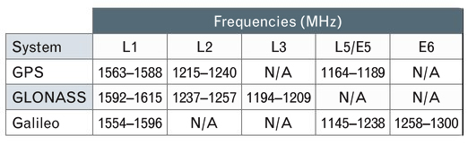
Frequency Coverage. GNSS receivers brought to market today may include frequency bands such as GPS L5, Galileo E5/E6, and the GLONASS bands in addition to the legacy GPS bands, and the antenna feeding a receiver may need to cover some or all of these bands.
TABLE 1 presents an overview of the frequencies used by the various GNSS constellations. Keep in mind that you may see slightly different numbers published elsewhere depending on how the signal bandwidths are defined.
TABLE 1. GNSS Frequency Allocations. (Data: Gerald J. K. Moernaut and Daniel Orban)
As the bandwidth requirement of an antenna increases, the antenna becomes harder to design, and developing an antenna that covers all of these bands and making it compliant with all of the other requirements is a challenge.
If small size is also a requirement, some level of compromise will be needed.
Gain Pattern. For a transmitting antenna, gain is the ratio of the radiation intensity in a given direction to the radiation that would be obtained if the power accepted by the antenna was radiated isotropically. For a receiving antenna, it is the ratio of the power delivered by the antenna in response to a signal arriving from a given direction compared to that delivered by a hypothetical isotropic reference antenna. The spatial variation of an antenna’s gain is referred to as the radiation pattern or the receiving pattern. Actually, under the antenna reciprocity theorem, these patterns are identical for a given antenna and, ignoring losses, can simply be referred to as the gain pattern.
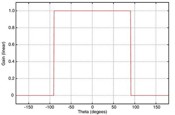
The receiver operates best with only a small difference in power between the signals from the various satellites being tracked and ideally the antenna covers the entire hemisphere above it with no variation in gain. This has to do with potential cross-correlation problems in the receiver and the simple fact that excessive gain roll-off may cause signals from satellites at low elevation angles to drop below the noise floor of the receiver.
On the other hand, optimization for multipath rejection and antenna noise temperature (see below) require some gain roll-off.
FIGURE 1. Theoretical antenna with hemispherical gain pattern. Boresight corresponds to θ = 0°. (Data: Gerald J. K. Moernaut and Daniel Orban)
FIGURE 1 shows what a perfect hemispherical gain pattern looks like, with a cut through an arbitrary azimuth.
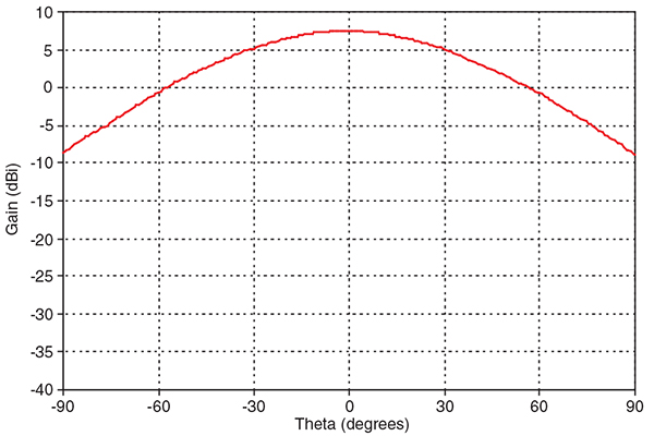
However, such an antenna cannot be built and “real-world” GNSS antennas see a gain roll-off of 10 to 20 dB from boresight (looking straight up from the antenna) to the horizon. FIGURE 2 shows what a typical gain pattern looks like as a cross-section through an arbitrary azimuth.
FIGURE 2. “Real-world” antenna gain pattern. (Data: Gerald J. K. Moernaut and Daniel Orban)
Circular Polarization. Spaceborne systems at L-Band typically use circular polarization (CP) signals for transmitting and receiving. The changing relative orientation of the transmitting and receiving CP antennas as the satellites orbit the Earth does not cause polarization fading as it does with linearly polarized signals and antennas. Furthermore, circular polarization does not suffer from the effects of Faraday rotation caused by the ionosphere. Faraday rotation results in an electromagnetic wave from space arriving at the Earth’s surface with a different polarization angle than it would have if the ionosphere was absent. This leads to signal fading and potentially poor reception of linearly polarized signals.
Circularly polarized signals may either be right-handed or left-handed. GNSS satellites use right-hand circular polarization (RHCP) and therefore a GNSS antenna receiving the direct signals must also be designed for RHCP.
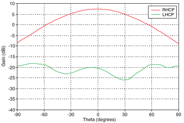
Antennas are not perfect and an RHCP antenna will pick up some left-hand circular polarization (LHCP) energy. Because GPS and other GNSS use RHCP, we refer to the LHCP part as the cross-polar component (see FIGURE 3).
FIGURE 3. Co- and cross-polar gain pattern versus boresight angle of a rover antenna. (Data: Gerald J. K. Moernaut and Daniel Orban)
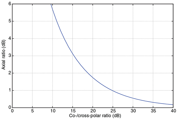
We can describe the quality of the circular polarization by either specifying the ratio of this cross-polar component with respect to the co-polar component (RHCP to LHCP), or by specifying the axial ratio (AR). AR is the measure of the polarization ellipticity of an antenna designed to receive circularly polarized signals. An AR close to 1 (or 0 dB) is best (indicating a good circular polarization) and the relationship between the co-/cross-polar ratio and axial ratio is shown in FIGURE 4.
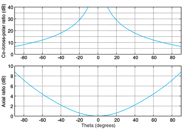
FIGURE 4. Converting axial ratio to co-/cross-polar ratio. (Data: Gerald J. K. Moernaut and Daniel Orban)FIGURE 5. Co-/cross-polar and axial ratios versus boresight angle of a rover-style antenna. (Data: Gerald J. K. Moernaut and Daniel Orban)
FIGURE 5 shows the ratio of the co- and cross-polar components and the axial ratio versus boresight (or depression) angle for a typical GPS antenna. The boresight angle is the complement of the elevation angle.
For high-end GNSS antennas such as choke-ring and other geodetic-quality antennas, the typical AR along the boresight should be not greater than about 1 dB. AR increases towards lower elevation angles and you should look for an AR of less than 3 to 6 dB at a 10° elevation angle for a high-performance antenna. Expect to see small (<1 dB) variations of AR versus azimuth at the low elevation angles.
Maintaining a good AR over the entire hemisphere and at all frequencies requires a lot of surface area in the antenna and can only be accomplished in high-end antennas like base station and rover antennas.
Multipath Suppression. Signals coming from the satellites arrive at the GNSS receiver’s antenna directly from space, but they may also be reflected off the ground, buildings, or other obstacles and arrive at the antenna multiple times and delayed in time. This is termed multipath. It degrades positioning accuracy and should be avoided. High-end receivers are able to suppress multipath to a certain extent, but it is good engineering practice to suppress multipath in the antenna as much as possible.
A multipath signal can come from three basic directions:
The ground and arrive at the back of the antenna.
The ground or an object and arrive at the antenna at a low elevation angle.
An object and arrive at the antenna at a high elevation angle.
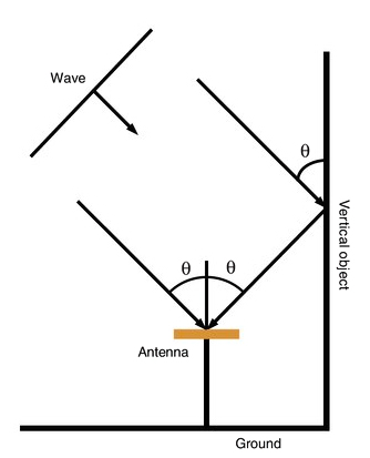
Reflected signals typically contain a large LHCP component. The technique to mitigate each of these is different and, as an example, we will describe suppression of multipath signals due to ground and vertical object reflections.
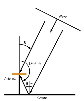
Multipath susceptibility of an antenna can be quantified with respect to the antenna’s gain pattern characteristics by the multipath ratio (MPR). FIGURE 6 sketches the multipath problem due to ground reflections.
FIGURE 6. Quantifying multipath caused by ground reflections. (Data: Gerald J. K. Moernaut and Daniel Orban)
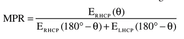
We can derive this MPR formula for ground reflections:
The MPR for signals that are reflected from the ground equals the RHCP antenna gain at a boresight angle (θ) divided by the sum of the RHCP and LHCP antenna gains at the supplement of that angle.
Signals that are reflected from the ground require the antenna to have a good front-to-back ratio if we want to suppress them because an RHCP antenna has by nature an LHCP response in the anti-boresight or backside hemisphere. The front-to-back ratio is nominally the difference in the boresight gain and the gain in the anti-boresight direction. A good front-to-back ratio also minimizes ground-noise pick-up.
Similarly, an MPR formula can be written for signals that reflect against vertical objects. FIGURE 7 sketches this.
FIGURE 7. Quantifying multipath caused by vertical object reflections. (Data: Gerald J. K. Moernaut and Daniel Orban)
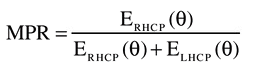
And the formula looks like this:
The MPR for signals that are reflected from vertical objects equals the RHCP antenna gain at a boresight angle (θ) divided by the sum of the RHCP and LHCP antenna gains at that angle.
Multipath signals from reflections against vertical objects such as buildings can be suppressed by having a good AR at those elevation angles from which most vertical object multipath signals arrive. This AR requirement is readily visible in the MPR formula considering these reflections are predominantly LHCP, and in this case MPR simply equals the co- to cross-polar ratio.
LHCP reflections that arrive at the antenna at high elevation angles are not a problem because the AR tends to be quite good at these elevation angles and the reflection will be suppressed. LHCP signals arriving at lower elevation angles may pose a problem because the AR of an antenna at low elevation angles is degraded in “real-world” antennas. It makes sense to have some level of gain roll-off towards the lower elevation angles to help suppress multipath signals. However, a good AR is always a must because gain roll-off alone will not do not it.
Phase Center. A position fix in GNSS navigation is relative to the electrical phase center of the antenna. The phase center is the point in space where all the rays appear to emanate from (or converge on) the antenna. Put another way, it is the point where the electromagnetic fields from all incident rays appear to add up in phase. Determining the phase center is important in GNSS applications, particularly when millimeter-positioning resolution is desired.
Ideally, this phase center is a single point in space for all directions at all frequencies. However, a “real-world” antenna will often possess multiple phase center points (for each lobe in the gain pattern, for example) or a phase center that appears “smeared out” as frequency and viewing angle are varied.
The phase-center offset can be represented in three dimensions where the offset is specified for every direction at each frequency band. Alternatively, we can simplify things and average the phase center over all azimuth angles for a given elevation angle and define it over the 10° to 90° elevation-angle range. For most applications even this simplified representation is over-kill, and typically only a vertical and a horizontal phase-center offset are specified for all bands in relation to L1.
For well-designed high-end GNSS antennas, phase center variations in azimuth are small and on the order of a couple of millimeters. The vertical phase offsets are typically 10 millimeters or less. Many high-end antennas have been calibrated, and tables of phase-center offsets for these antennas are available.
Impact on Receiver Sensitivity. The strength of the signals from space is on the order of -130 dBm. We need a really sensitive receiver if we want to be able to pick these up. For the antenna, this translates into the need for a high-performance low noise amplifier (LNA) between the antenna element itself and the receiver.
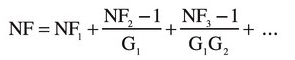
We can characterize the performance of a particular receiver element by its noise figure (NF), which is the ratio of actual output noise of the element to that which would remain if the element itself did not introduce noise. The total (cascaded) noise figure of a receiver system (a chain of elements or stages) can be calculated using the Friss formula as follows:
The total system NF equals the sum of the NF of the first stage (NF1) plus that of the second stage (NF2) minus 1 divided by the total gain of the previous stage (G1) and so on. So the total NF of the whole system pretty much equals that of the first stage plus any losses ahead of it such as those due to filters.
Expect to see total LNA noise figures in the 3-dB range for high performance GNSS antennas.
The other requirement for the LNA is for it to have sufficient gain to minimize the impact of long and lossy coaxial antenna cables — typically 30 dB should be enough. Keep in mind that it is important to have the right amount of gain for a particular installation. Too much gain may overload the receiver and drive it into non-linear behavior (compression), degrading its performance. Too little, and low-elevation-angle observations will be missed. Receiver manufacturers typically specify the required LNA gain for a given cable run.
Interference Handling. Even though GNSS receivers are good at mitigating some kinds of interference, it is essential to keep unwanted signals out of the receiver as much as possible. Careful design of the antenna can help here, especially by introducing some frequency selectivity against out-of-band interferers. The mechanisms by which in-band an out-of-band interference can create trouble in the LNA and the receiver and the approach to dealing with them are somewhat different.
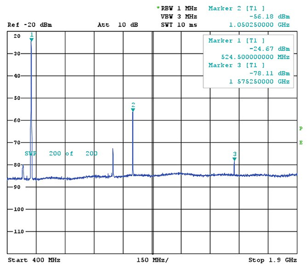
FIGURE 8. Strong out-of-band interferer and third harmonic in the GPS L1 band. (Data: Gerald J. K. Moernaut and Daniel Orban)
An out-of-band interferer is generally an RF source outside the GNSS frequency bands: cellular base stations, cell phones, broadcast transmitters, radar, etc. When these signals enter the LNA, they can drive the amplifier into its non-linear range and the LNA starts to operate as a multiplier or comb generator. This is shown in FIGURE 8 where a -30-dBm-strong interferer at 525 MHz generates a -78 dBm spurious signal or spur in the GPS L1 band.
Through a similar mechanism, third-order mixing products can be generated whereby a signal is multiplied by two and mixes with another signal. As an example, take an airport where radars are operating at 1275 and 1305 MHz. Both signals double to 2550 and 2610 MHz. These will in turn mix with the fundamentals and generate 1245 and 1335 MHz signals.
Another mechanism is de-sensing: as the interference is amplified further down in the LNA’s stages, its amplitude increases, and at some point the GNSS signals get attenuated because the LNA goes into compression. The same thing may happen down the receiver chain. This effectively reduces the receiver’s sensitivity and, in some cases, reception will be lost completely.
RF filters can reduce out-of-band signals by 10s of decibels and this is sufficient in most cases. Of course, filters add insertion loss and amplitude and phase ripple, all of which we don’t want because these degrade receiver performance.
In-band interferers can be the third-order mixing products we mentioned above or simply an RF source that transmits inside the GNSS bands. If these interferers are relatively weak, the receiver will handle them, but from a certain power level on, there is just not a lot we can do in a conventional commercial receiver.
The LNA should be designed for a high intercept point (IP)–at which non-linear behavior begins–so compression does not occur with strong signals present at its input. On the other hand, there is no requirement for the LNA to be a power amplifier. As an example, let’s say we have a single strong continuous wave interferer in the L1 band that generates -50 dBm at the input of the LNA. A 50 dB, high IP LNA will generate a 0 dBm carrier in the L1 band but the receiver will saturate.
LNAs with a higher IP tend to consume more power and in a portable application with a rover antenna — that may be an issue. In a base-station antenna, on the other hand, low current consumption should not be a requirement since a higher IP is probably more valuable than low power consumption.
GNSS Antenna Types
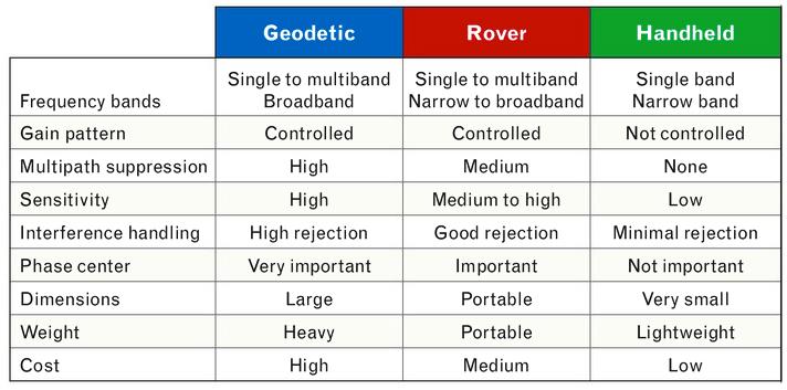
Here is a short comparison of three types of GNSS antennas: geodetic, rover, and handheld. For detailed specifications of examples of each of these types, see the references in Further Reading.
Geodetic Antennas. High precision, fixed-site GNSS applications require geodetic-class receivers and antennas. These provide the user with the highest possible position accuracy.
As a minimum, typical geodetic antennas cover the GPS L1 and L2 bands. Some also cover the GLONASS frequencies. Coverage of L5 is found in some newer designs as well as coverage of the Galileo frequencies and the L-band frequencies of differential GNSS services.
The use of choke-ring ground planes is typical in geodetic antennas. These allow good gain pattern control, excellent multipath suppression, high front-to-back ratio, and good AR at low elevation angles. Choke rings contribute to a stable phase center. The phase center is documented (as mentioned earlier), and high-end receivers allow the antenna behavior to be taken into account. Combined with a state-of-the-art LNA, these antennas provide the highest possible performance.
Rover Antennas. Rover antennas are typically used in land survey, forestry, construction, and other portable or mobile applications. They provide the user with good accuracy while being optimized for portability. Horizontal phase-center variation versus azimuth should be low because the orientation of the antenna with respect to magnetic north, say, is usually unknown and cannot be corrected for in the receiver. A rover antenna is typically mounted on a handheld pole. Good front-to-back ratio is required to avoid operator-reflection multipath and ground-noise pickup. Yet these rover-type applications are high accuracy and require a good phase-center stability. However, since a choke ring cannot be used because of its size and weight, a higher phase-center variation compared to that of a geodetic antenna is typically inherent to the rover antenna design.
A good AR and a decent gain roll-off at low elevation angles ensures good multipath suppression as heavy choke rings are not an option for this configuration.
Handheld Receiver Antennas. These antennas are single-band L1 structures optimized for size and cost. They are available in a range of implementations, such as surface mount ceramic chip, helical, and patch antenna types. Their radiation patterns are quasi-hemispherical. AR and phase-center performance are a compromise because of their small size. Because of their reduced size, these antennas tend to have a negative gain of about -3 dBi (3 dB less than an ideal isotropic antenna) at boresight. This negative gain is mostly masked by an embedded LNA. The associated elevated noise figure is typically not an issue in handheld applications.
TABLE 2. Characteristics of different GNSS antenna classes. (Data: Gerald J. K. Moernaut and Daniel Orban)
Summary of Antenna Types. TABLE 2 presents a comparison of the most important properties of geodetic, rover, and handheld types of GNSS antennas.
Conclusion
In this article, we have presented an overview of the most important characteristics of GNSS antennas. Several GNSS receiver-antenna classes were discussed based on their typical characteristics, and the resulting specification compromises were outlined. Hopefully, this information will help you select the right antenna for your next GNSS application.
Acknowledgment
An earlier version of this article entitled “Basics of GPS Antennas” appeared in The RF & Microwave Solutions Update, an online publication of RF Globalnet.
GERALD J. K. MOERNAUT holds an M.Sc. degree in electrical engineering. He is a full-time antenna design engineer with Orban Microwave Products, a company that designs and produces RF and microwave subsystems and antennas with offices in Leuven, Belgium, and El Paso, Texas.
DANIEL ORBAN is president and founder of Orban Microwave Products. In addition to managing the company, he has been designing antennas for a number of years.
FURTHER READING
Previous GPS World Articles on GNSS Antennas
“Getting into Pockets and Purses: Antenna Counters Sensitivity Loss in Consumer Devices” by B. Hurte and O. Leisten in GPS World, Vol. 16, No. 11, November 2005, pp. 34-38.
“Characterizing the Behavior of Geodetic GPS Antennas” by B.R. Schupler and T.A. Clark in GPS World, Vol. 12, No. 2, February 2001, pp. 48-55.
“A Primer on GPS Antennas” by R.B. Langley in GPS World, Vol. 9, No. 7, July 1998, pp. 50-54.
“How Different Antennas Affect the GPS Observable” by B.R. Schupler and T.A. Clark in GPS World, Vol. 2, No. 10, November 1991, pp. 32-36.
Introduction to Antennas and Receiver Noise
“GNSS Antennas and Front Ends” in A Software-Defined GPS and Galileo Receiver: A Single-Frequency Approach by K. Borre, D.M.Akos, N. Bertelsen, P. Rinder, and S.H. Jensen, Birkhäuser Boston, Cambridge, Massachusetts, 2007.
The Technician’s Radio Receiver Handbook: Wireless and Telecommunication Technology by J.J. Carr, Newnes Press, Woburn, Massachusetts, 2000.
“GPS Receiver System Noise” by R.B. Langley in GPS World, Vol. 8, No. 6, June 1997, pp. 40-45.
More on GNSS Antenna Types
“The Basics of Patch Antennas” by D. Orban and G.J.K. Moernaut. Available on the Orban Microwave Products website.
GMV, a supplier of satellite ground system software headquartered in Madrid,
Spain, with a significant role in Europe’s Galileo program, has announced
the appointment of Jesus Serrano as its new Chief Executive Officer (CEO).
Serrano, 48, replaces Luis Mayo in his position as the business group’s top
executive, reporting directly to the board.
With more than 20 years of experience through various management positions
at GMV, this Spanish native will continue to lead the multinational technology
group and expand their products and services to its customers throughout the
U.S., South America, Africa, Asia and Oceania.
The U.S. International Trade Commission (ITC) has issued an exclusion order against certain SiRF GPS chips and products containing those chips imported into the United States, as well as cease-and-desist orders against SiRF and four specific SiRF customers.
This comes after the commission affirmed an ITC administrative law judge’s initial determination that SiRF infringes on three additional GPS patents held by Global Locate Inc., a wholly owned subsidiary of Broadcom. This latest ruling brings the total number of Global Locate GPS-related patents that SiRF has been found to infringe up to six.
In 2008, an ITC administrative law judge found that SiRF infringed on all six patents asserted by Global Locate/Broadcom and subsequently recommended an import ban within in the United States; SiRF appealed the finding. The full ITC Commission subsequently upheld the administrative law judge’s finding on three patents, while holding off on a final determination on the other three pending further review. On Thursday, January 15, the commission issued both its Final Determination on those patent issues and orders regarding the appropriate form of remedy.
“We are optimistic that the ITC orders will become effective after a 60-day statutory review period so that U.S. Customs may begin enforcement and prevent any further patent infringement,” said David Rosmann, Broadcom’s vice president for intellectual property litigation.
The six patents at the center of the dispute are United States patents 6,417,801; 6,937,187; 6,606,346; 7,158,080; 6,704,651; and 6,651,000 — relating to extended ephemeris assistance, calculating time in GPS receivers, enhancing sensitivity in assisted GPS systems, and implementing hardware structures for parallel correlation, according to Broadcom. These patents involve several SiRF products, including SiRFstarIII and SiRFInstant devices.
For its part, however, SiRF said that the impact of the ITC’s decision is minimal, as the products involved are legacy products. It also hinted that it could still file an appeal in federal court.
“We are pleased that the commission followed the Federal Circuit’s Kyocera ruling, which significantly limits the impact to our customer base,” said Kanwar Chadha, founder of SiRF in a statement. “While disappointed with the commission’s ruling as it relates to its patent infringement findings regarding SiRF’s earlier products, we continue to work closely with the named customers to conform with the commission’s ruling and enable them to maintain uninterrupted product delivery to market.”
Chadha was referring to a federal circuit court’s October 14, 2008, decision that ITC limited exclusion orders only affect parties named in an investigation involving Kyocera. Other than the four named customers in the investigation, all other SiRF customers are not affected, the company said. Those four customers have not been named publicly.
SiRF further noted that following the 60-day presidential review period it has the option to appeal the case to the U.S. Court of Appeals for the Federal Circuit, but did not specifically say it would pursue this option. Broadcom and SiRF are already duking it out in federal district court over patent disputes; that trial is scheduled to begin in November 2010.
Capitol Appraisal Group Inc. (CAGI) has contracted with the Sidwell Co., asking it to provide a system to inventory, value, and keep track of oil and gas infrastructure and the land parcels on which they are built.
CAGI provides appraisal and information services to governmental entities primarily for the purpose of property taxation. It contracted with Sidwell after deciding to pursue a geographic information system that would facilitate the collection of field appraisal data.
This project will be completed in three phases, according to Sidwell and CAGI. The first phase includes review of the typical workflow for field data collection as performed by CAGI technicians, development of a prototype database design, creation of custom forms for ArcPad data capture, and the design and implementation of a system to associate digital camera images directly to records in the ArcPad database.
Phase Two will consist of refinement of the data capture forms and database design to enhance the data collection workflow, and on-site installation, configuration, testing, and training. Phase Three, the enterprise deployment of the entire system, will include installation and configuration of ESRI’s ArcGIS Server, data loading and tuning, technical consulting, and ArcGIS Server administrator training, according to Sidwell and CAGI.
 Chadha Says. “From a strategy viewpoint,” SiRF founder and vice president of marketing Kanwar Chadha told GPS World, “multi-function radios is something we have been talking about for two years. Market opportunities became much larger in the last six months, with Nokia driving loction into every mobile phone.
 Epson, Infineon Develop Tiny Single-Chip Receiver
 u-blox Launches Cards for Mobile Computers