A portable spoofer implemented on a digital signal processor mounts a spoofing attack, characterizes spoofing effects, and suggests possible defense tactics. GNSS users and receiver manufacturers should explore and implement authentication methods against sophisticated spoofing attacks.
By Todd E. Humphreys, University of Texas, Brent A. Ledvina, Virginia Tech, Mark L. Psiaki, Brady W. O’Hanlon, and Paul M. Kitner, Jr., Cornell University
Seven years after the Volpe Report warned that “[a]s GPS further penetrates into the civil infrastructure, it becomes a tempting target that could be exploited by individuals, groups, or countries hostile to the U.S.,” civil GPS receivers remain as vulnerable as ever to this threat. Among other types of interference, the Volpe report considers civil GPS spoofing, a pernicious type of intentional interference whereby a GPS receiver is fooled into tracking counterfeit GPS signals. More sinister than intentional jamming, spoofing deceives the targeted receiver, which cannot detect a spoofing attack and so cannot warn users that its navigation solution is untrustworthy. The Volpe report noted the absence of any off-the-shelf defense against civilian spoofing and lamented that “[t]here also is no open information on . . . the expected capabilities of spoofing systems made from commercial components.” It recommended studies to characterize the spoofing threat: “Information on the capabilities, limitations, and operational procedures [of spoofers] would help identify vulnerable areas and detection strategies.”
We recently canvassed four manufacturers of high-quality GPS receivers. They revealed that they were aware of the spoofing vulnerability but had not taken steps to equip their receivers with even rudimentary spoofing countermeasures. The manufacturers expressed skepticism about the seriousness of the threat and noted that countermeasures, if required, had better not be too expensive. Such attitudes propel further examination of the threat and practical countermeasures.
Important research into spoofing countermeasures during the last decade begins with an internal memorandum from the MITRE Corporation recommending these techniques to counter spoofing:
- Amplitude discrimination
- Time-of-arrival discrimination
- Consistency of navigation inertial measurement unit (IMU) cross-check
- Polarization discrimination
- Angle-of-arrival discrimination
- Cryptographic authentication
The first two techniques could be implemented in software on GPS receivers, but would be effective against only the most simplistic attacks. The next three tactics would be effective against some — but not all — more sophisticated attacks. In particular, angle-of-arrival discrimination, which exploits differential carrier-phase measurements taken between multiple antennas, could only be spoofed by a sophisticated coordinated spoofing attack (discussed later). However, they require additional hardware: multiple antennas or a high-grade IMU, whose cost militates against widespread adoption.
Cryptographic authentication, the last technique on the list, has received detailed study since 2001. Logan Scott offered several levels of authentication in a 2003 ION GPS/GNSS paper and urged their prompt adoption in a GPS World op-ed column in July 2007. His methods are backward-compatible with non-compliant GPS receivers. Spreading-code authentication, the basis for his Level 2 and 3 authentication, entails embedding messages in the GPS ranging codes and periodically authenticating these messages. Because this method effectively binds a digital signature to the ranging codes, it would render a compliant receiver practically impervious to a spoofing attack except during the short interval between reception and authentication of the embedded messages.
These cryptographic techniques all require modification of the civil GPS signal structure. Such changes appear extremely unlikely in the short term because, as one experienced observer noted, “signal definition inertia is enormous.” A less effective but more practical approach over the United States would be to authenticate only the WAAS signal managed by the U.S. Department of Transportation and the Federal Aviation Administration. Since the WAAS signal is constructed on the ground and transmitted via bent-pipe communication spacecraft, it is more amenable to immediate modification. Even so, efforts to persuade WAAS officials to adopt spreading code authentication have so far proven fruitless.
The Homeland Security Institute, a research arm of the U.S. Department of Homeland Security, has also considered the threat of civil GPS spoofing. On its website it has posted a report listing seven spoofing countermeasures. The proposed countermeasures include the first three techniques from the list here. Some of the remaining four countermeasures would be trivial to spoof. None of the seven would adequately defend against a sophisticated attack. Nonetheless, the posting claims that its proposed techniques “should allow suspicious GPS signal activity to be detected.” We worry that such optimistic language in such a prominent posting will mislead many readers into believing that the spoofing threat has been adequately addressed.
Our goals here are to assess the spoofing threat and develop and test practical and effective countermeasures. To advance these goals we found it necessary to go through the exercise of building a civil GPS spoofer. The process of developing a complete portable spoofer allows one to explore the range of practical spoofing techniques. Thus one discovers which aspects of spoofing are hard and which are easy to implement in practice. With this information, we can more accurately assess the difficulty of mounting an attack, and receiver developers can prioritize their defenses by choosing countermeasures that are effective against easily implementable spoofing techniques.
Software-defined GPS receivers furnish a natural platform for the study of civil spoofing and its effects. In a software receiver, real-time correlators, tracking loops, and navigation solver are all implemented in software on a programmable processor.
Initial Threat Assesment
Consider the spoofing threat continuum in FIGURE 1, roughly divided into simplistic, intermediate, and sophisticated spoofing attacks for threat analysis.
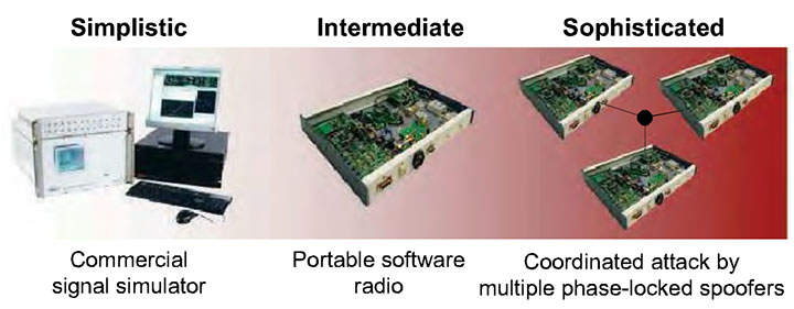
Simplistic Attack via Simulator. As far as we know, all stand-alone commercial civilian GPS receivers available today are trivial to spoof. One simply attaches a power amplifier and an antenna to a GPS signal simulator and radiates the RF signal toward the target receiver. A successful attack along these lines was demonstrated by researchers at Argonne National Laboratories in 2002.
Despite the ease of such an attack, it has some drawbacks. One is cost: the price of modern simulators can reach $400,000. Simulators can be rented for less than $1,000 per week, making them accessible for short-term mischief, but long-term use remains costly. Size is another drawback. Most GPS signal simulators are heavy and cumbersome. If used in the simplest attack mode, situated close to a target receiver’s antenna, a signal simulator would be challenging to plant and visually conspicuous. Of course, if the custodian of the target receiver is complicit in the spoofing attack — as is the case, for example, with the fishing vessel skipper who spoofs the onboard monitoring unit to fish undetected in forbidden waters — the conspicuousness of the signal spoofer is irrelevant.
The menace posed by such an attack is diminished by the fact that it is likely easy to detect, because of the difficulty of synchronizing a simulator’s output with the GPS signals in its vicinity. An unsynchronized attack effectively acts like signal jamming, and may cause the victim receiver to lose lock and have to undergo a partial or complete reacquisition. Such a forced re-acquisition would raise suspicion of a spoofing attack. If the unsynchronized attack somehow avoids causing loss-of-lock, it will nonetheless cause an abrupt change in the victim receiver’s GPS time estimate. The victim receiver could flag jumps of more than 100 nanoseconds as evidence of possible spoofing. The spoofer can attempt to counter this defense by intentionally jamming first and then spoofing, but an extended jamming is itself telltale evidence of interference.
Of course, the fact that a simulator-type attack is easy to defend does not increase security. A gaping vulnerability will remain until civil GPS receivers at least are equipped with the rudimentary spoofing countermeasures required to detect a simulator-type attack.
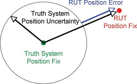
Intermediate Attack. One of the challenges that must be overcome to carry out a successful spoofing attack is to gain accurate knowledge of the target receiver antenna’s position and velocity. This knowledge is required to precisely position the counterfeit signals relative to the genuine signals at the target antenna. Without such precise positioning, a spoofing attack is easily detected.
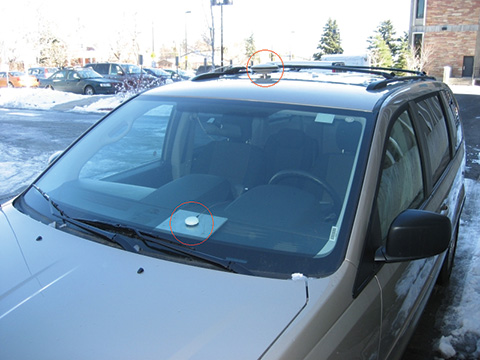
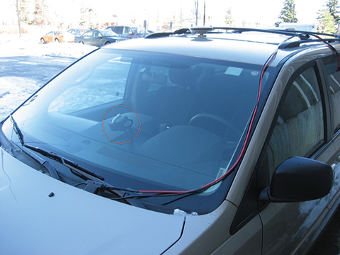
An attack via portable receiver-spoofer, portrayed in FIGURE 2, overcomes this difficulty by construction. The receiver-spoofer can be made small enough for inconspicuous placement near the target receiver’s antenna. The receiver component draws in genuine GPS signals to estimate its own position, velocity, and time. Due to proximity, these apply approximately to the target antenna. Based on these estimates, the receiver-spoofer then generates counterfeit signals and generally orchestrates the spoofing attack. The portable receiver-spoofer could even be placed somewhat distant from the target receiver if the target were static and its position relative to the receiver-spoofer had been pre-surveyed.
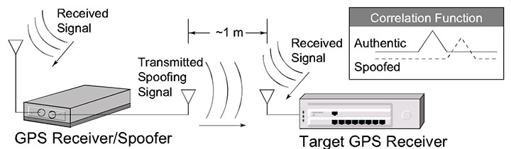
Each channel of the target receiver is brought under control of the receiver-spoofer as illustrated in the inset at the upper right of Figure 2. The counterfeit correlation peak is aligned with the peak corresponding to the genuine signal. The power of the counterfeit signal is then gradually increased. Eventually, the counterfeit signal gains control of the delay-lock loop tracking points that flank the correlation peak.
As one might imagine, there are no commercially available portable receiver-spoofer devices. This of course decreases the present likelihood of the receiver-spoofer attack mode. Nonetheless, the emergence of software-defined GPS receivers significantly erodes this barrier. As we demonstrate here, the hardware for a receiver-spoofer can be assembled from inexpensive off-the-shelf components. The software remains fairly sophisticated, but it would be unwise to assume it was beyond the capabilities of clever malefactors. The civil GPS signal structure is, after all, completely detailed in a publicly available interface control document, and entire books have been written on software-defined GPS receivers. In perhaps the most worrisome scenario, anticipated in Scott’s 2003 paper, the software definition of a receiver-spoofer may someday be available for download from the Internet. The expertise required to download and exercise the code would surely be within the reach of many potential malefactors.
An attack via portable receiver-spoofer could be difficult to detect. The receiver-spoofer can synchronize its signals to GPS time and, by virtue of its proximity to the target antenna, align the counterfeit and genuine signals. A receiver equipped with a stable reference oscillator and a low-drift inertial measurement unit (IMU, for receivers on dynamic platforms) could withstand an attack via receiver-spoofer for several hours. Eventually, however, a patient receiver-spoofer would gain undetected control by keeping its perturbations to time and position within the envelope allowed by the drift rates of the target receiver’s oscillator and IMU.
The only known user-equipment-based countermeasure that would be completely effective against an attack launched from a portable receiver-spoofer with a single transmitting antenna is angle-of-arrival discrimination. With a single transmitting antenna, it would be impossible to continuously replicate the relative carrier phase between two or more antennas of an appropriately equipped target receiver.
While an intermediate attack is not presently likely because the requisite device is not readily available, the emergence of software-defined GPS receivers increases its future likelihood. Furthermore, this mode of attack could defeat most known user-equipment-based spoofing countermeasures.
Sophisticated Attack. The angle-of-arrival defense against a portable receiver-spoofer can be thwarted by a coordinated attack with as many receiver-spoofers as antennas on the target receiver. Imagine a receiver-spoofer the size of a pack of cards, small enough to mount directly atop a target antenna. The receiver-spoofer’s receiving and transmitting antennas are situated respectively on the upper and lower faces of the device and are shielded to avoid self-spoofing. Now imagine several such devices sharing a common reference oscillator and communication link, with each device mounted to one of the target receiver’s antennas. The angle-of-arrival defense fails under this attack scenario.
Naturally, this attack inherits all of the challenges of mounting a single receiver-spoofer attack, with the additional expense of multiple receiver-spoofers and the additional complexity that the perturbations to the incoming signals must be phase-coordinated.
The only known defense against such an attack is cryptographic authentication.
Thus, an attack via multiple phase-locked portable receiver-spoofers is somewhat less likely than an attack via single portable receiver-spoofer, but may be impossible to detect with user-equipment-based spoofing defenses.
Target Spoofer Type. The foregoing discussion of the spoofing threat continuum suggests that a spoofing attack via GPS signal simulator poses the greatest near-term threat. However, there are known effective defenses against such an attack, and these can be implemented in software on commercial GPS receivers. In contrast, an attack launched from one or more portable receiver-spoofer(s) poses the greatest long-term threat. Known user-equipment-based defenses against such attacks are few and of limited effectiveness. Accordingly, we focus here on the portable receiver-spoofer attack mode. To better understand this mode, we built a software-defined portable receiver-spoofer as a research platform.
Architecture
We developed a software-defined receiver-spoofer as an extension of the Cornell GRID receiver, adding a spoofer software module and transmission hardware; see FIGURE 3.
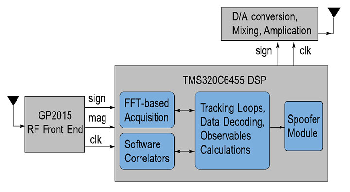
Receiver Module. The hardware consists of an RF front end, a complex programable logic device (CPLD) for signal multiplexing (not shown), and a digital signal processor (DSP). The receiver software includes a full navigation solution engine. Software is entirely written in natural-language C++ to facilitate code development and maintenance.
The software correlation engine, based on a bit-wise parallel correlation technique, is crucial to meeting real-time deadlines in the receiver-spoofer under the simultaneous burdens of receiver processing and spoofing. Here is an overview.
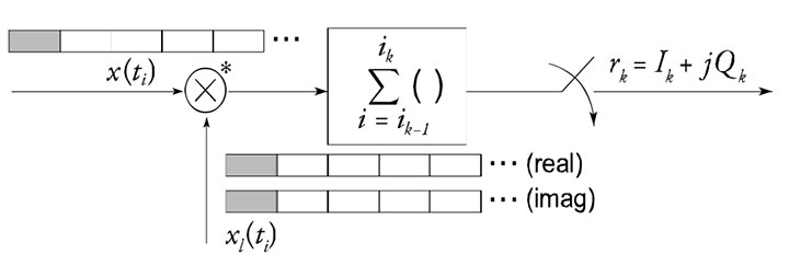
FIGURE 4 depicts the standard correlation operation that occurs within any GPS receiver. The incoming signal x(t) is mixed by complex multiplication with a complex local signal replica, x l (t). The product is integrated over a short interval (typically 1–20 milliseconds) and sampled to produce the quadrature baseband components I k and Q k , also known as baseband accumulations.
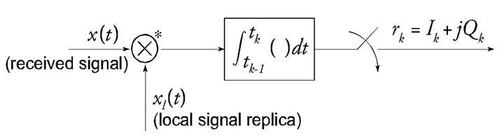
FIGURE 5 depicts a byte-wise software implementation of the standard correlation operation. In this implementation, the individual signal samples are stored in 8-bit bytes.
Because many DSPs and general-purpose CPUs are capable of performing several multiply-and-accumulate operations in parallel (for example, eight in high-performance fixed-point DSPs), the byte-wise implementation can be quite computationally efficient. However, storing the local carrier and code replica samples as bytes makes the tables in which they are packed for efficient table look-up prohibitively large for storage in on-chip (fast) memory. Furthermore, despite its computational efficiency, the byte-wise implementation is still only one-quarter to one-half as fast as the bit-wise parallel implementation when implemented on a high-performance fixed-point DSP.
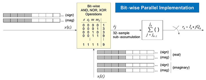
FIGURE 6 depicts the bit-wise parallel correlation implementation. The operation assumes the incoming signal and the local signal replicas are quantized to two bits — one sign and one magnitude bit. The sign and magnitude bits are packed into 32-bit words. Explicit complex multiplication is replaced by a combination of the bit-wise logical operations AND, NOR, and XOR. In effect, the bitwise parallel method performs 32 multiply-and-accumulate operations in parallel. Importantly, storage of the local carrier replicas as bit-packed sign and magnitude words is also memory-efficient, which makes on-chip storage of the local signal replica look-up tables possible.
Spoofer Module. Beyond the hardware required for the GPS receiver, the receiver-spoofer requires only signal transmission hardware: a digital/analog converter, a frequency synthesizer and mixer for mixing to near the GPS L1 frequency, in-line attenuators, and a transmission antenna. For this article, we conducted no over-the-air tests to avoid possible FCC violations; hence, we do not further discuss the transmission hardware.
The heart of the spoofer is the spoofer software module, shown in FIGURE 7.
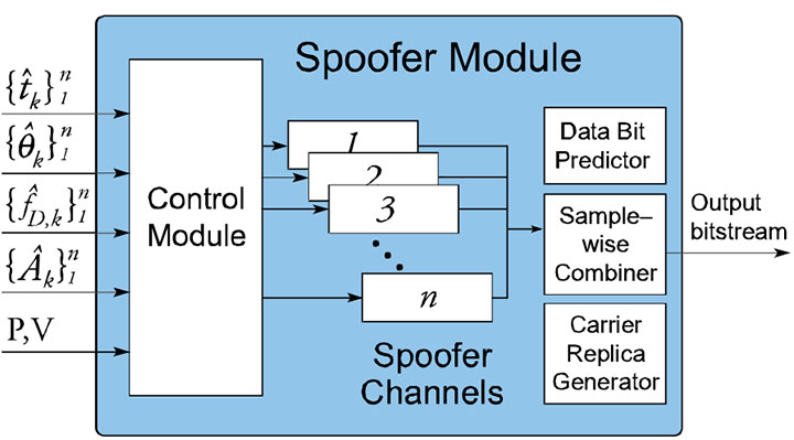
Control Module: The spoofer’s control module coordinates a spoofing attack by directing the frequency, code-phase offset, and signal amplitude applied in each of n spoofing channels. Some components of the control module described here remain under development.
The control module accepts the following inputs from the receiver module:
- estimates {t (circumflex) k } 1 n of the start times of the kth C/A code period on receiver channels 1–n;
- the estimates {θ (circumflex) k } 1 n of the beat carrier phase on receiver channels 1–n at times {t (circumflex) k } 1 n ;
- the estimates {f (circumflex) D,k } 1 n of the Doppler frequency shift on receiver channels 1–n at times {t (circumflex) k } 1 n ;
- the estimates {A (circumflex) k } 1 n of the signal amplitudes on receiver channels 1–n at times {t (circumflex) k } 1 n ;
- the receiver-spoofer’s current 3-dimensional position P and velocity V.
The control module orchestrates a spoofing attack in the following way. It begins by commanding n spoofer channels to generate signals with Doppler frequency offsets equal to {f (circumflex) D,k } 1 n and code phases whose relative alignment is equivalent to that dictated by {t (circumflex) k } 1 n . It then applies a common-mode code phase advance to compensate for buffering delays within the receiver-spoofer. If this advance is chosen correctly, then each spoofing signal will be code-phase-aligned with its genuine-signal counterpart at the target receiver’s antenna. The control module then commands an increase in the signal amplitude of one or more spoofer channels to effect lift-off of the target receiver’s tracking points. This continues until all target receiver channels are presumed to be under control of the spoofer.
At this point the control module gradually leads the target receiver off its true position and time to an alternate position or time. Let Δx D (t k ) = [Δv x (t k ), Δv y (t k ), Δv z (t k ), Δb •(t k )] T be the perturbation that the control module applies to the target receiver’s observed velocity and clock rate bias at receiver-spoofer time t k . The time rate of change of the perturbation Δb •(t k ) must be less than the expected drift rate of the target receiver’s reference oscillator. Likewise, the time rate of change of the velocity perturbations Δv x (t k ), Δv y (t k ), and Δv z (t k ) must be less than the accelerations that the target receiver expects, or, if the target receiver is equipped with an IMU, less than the expected uncertainty in the accelerometer bias.
To enforce Δx D (t k ), the control module linearizes the standard Doppler frequency measurement model about the current receiver time, position, and velocity estimates and computes offsets to the quantities {f (circumflex) D,k } 1 n that are commensurate with the perturbation Δx D (t k ).
Similarly, let Δx(t k ) = [Δx(t k ), Δy(t k ), Δz(t k ), Δt(t k )] T be the perturbation that the control module applies to the target receiver’s observed position and time at receiverspoofer time t k . Δx(t k ) is calculated by integrating the time history of Δx D (t k ) values from some initial condition, typically Δx D (t k ) = 0 so that the target receiver’s observed velocity and clock rate bias is initially approximately equal to its true velocity and clock rate bias. To enforce Δx(t k ), the control module linearizes the standard pseudorange measurement model about the current receiver time and position estimates and computes offsets to the quantities {t (circumflex) k } 1 n that are commensurate with the perturbation Δx(t k ).
Following this strategy, the control module can, as gradually as necessary, misdirect the target receiver’s observed position and time.
The spoofer control module currently makes no attempt to align the beat carrier phases of its output signals with those of the received GPS signals, and so the phase values {θ (circumflex) k } 1 n are currently discarded. More sophisticated future versions of the receiver-spoofer will likely make use of these phase values.
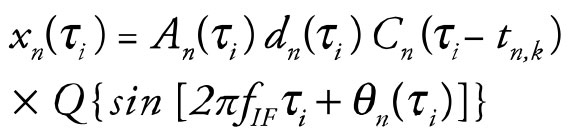
- Spoofer Channels: Each of the n spoofer channels is configured to correspond to one of the n authentic GPS signals that the receiver module tracks. The signal generated by the nth spoofer channel can be modeled as
 (1)
(1)
![]() (2)
(2)
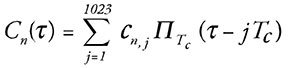
where x n (τ i ) is the ith sample of the signal, τ i is the time of the ith sample, A n (τ i ) is the control-module-commanded amplitude at τ i , d n (τ i ) is the data bit value that applies at τ i , C n (τ i –t n,k ) is the C/A code chip value that applies at τ i , t n,k is the control-module-commanded start time of the kth C/A code period, Q{•} is a 2-bit quantization function, f IF is the intermediate frequency, θ n (τ i ) is the beat carrier phase at τ i , and f D,n,k is the control-module-commanded Doppler frequency shift at time t n,k . The C/A code function C n (τ) can be further represented as
 (3)
(3)
and the data bit function d n (τ) as
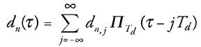 (4)
(4)
where {c n,1 , c n,2 , …, c n,1023 } and {d n,j , d n,j+1 , …} are the unique C/A code chip sequence and navigation data bit sequence corresponding to the GPS satellite whose signal is being emulated on the nth spoofer channel, T c and T d are the duration of one C/A code chip and one navigation data bit, and ∏ T (τ) is the usual rectangular support function equal to unity over 0 ≤ τ< T and zero otherwise.
To generate the C/A code samples {C n (τ i )}, i = 1,2, …, the spoofer channels make use of the same bit-packed C/A code replicas that are employed for signal correlation in the receiver module, which are stored in large look-up tables. However, to generate the samples of the quantized carrier replica
![]() (5)
(5)
the spoofer channels cannot exploit the same bit-packed carrier replicas that are used for signal correlation in the receiver. This is because, to minimize on-chip memory requirements, the receiver’s carrier replicas all begin at the same phase value and have only a coarse 175-Hz frequency resolution. The receiver compensates for these factors by performing a rotational “fix-up” on the in-phase and quadrature accumulation values. Unfortunately, such a scheme is unworkable for generating the sampled carrier replicas in the spoofer channels because anything less than precise phase and frequency control over the carrier replicas would potentially alert a target receiver to a spoofing attack. Consequently, it was necessary to develop a carrier-replica generator more capable than that used in the receiver module.
- Carrier-Replica Generator: Two requirements drove the carrier-replica generator design: precision and efficiency. Regarding precision, to evade detection the generator must be able to set the initial phase of a carrier replica segment to within approximately one degree and the Doppler frequency offset over the segment to within approximately 1 Hz. Regarding efficiency, to meet real-time deadlines the generator would have to be capable of generating a replica segment T S seconds long in less than T S /30 seconds. We developed a generator meeting these requirements.
A quantized sampled carrier replica can be represented in bit-wise parallel format as a block of 32-bit words. In the simplest case, the carrier replicas are one-bit quantized with 0 and 1 respectively representing the values –1 and 1. The carrier replica generator can be configured to generate 1- to 4-bit-quantized samples. Two-bit quantization was chosen for implementation within the spoofer, with one bit representing the sign and the other representing the magnitude of the signal. The choice of 2-bit quantization balanced a tradeoff between efficiency and the amount of quantization noise introduced into the final linear combination of the spoofer channel outputs.
The carrier replicas are sampled at a rate f S > 2f IF Hz as shown for the minimum and maximum Doppler frequency shifts in FIGURE 8. The key observation that makes real-time generation of the carrier replicas possible is the following: There is little diversity in the 32-bit words that result from packing 32 samples of quantized carrier replicas over a ±10-kHz range of Doppler frequency offsets and 2π radians of carrier phase. This is another way of saying that the information content of the quantized sampled carrier replicas is low, which is to be expected.
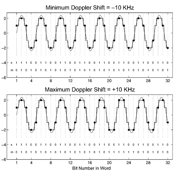
Figure 8 illustrates this concept by showing a case with a sampling frequency f S = 5.714 MHz, an intermediate frequency f IF = 1.405 MHz, and a Doppler frequency range of ±10kHz. This Doppler frequency range covers the expected range of Doppler shifts seen by a terrestrial GPS receiver, with ~ 5 kHz of margin for receiver clock rate error. The sampling and intermediate frequencies are typical for civil GPS applications. Over the interval shown in Figure 8, the total number of cycles for the two signals, whose initial phases are aligned, differs by less than 1/8 of a cycle. When sampled and 2-bit quantized into the sign (s) and magnitude (m) bits that run along the bottom of each frame, the resultant carrier replicas have the same sign-bit history and only 10 different magnitude bits. This indicates that the sampled carrier replicas covering a reasonable Doppler shift frequency range are primarily a function of the initial phase offset for each 32-bit word. This observation remains true whenever f IF < f S and f D,mabs << f IF , where f D,mabs is the maximum absolute value of the Doppler frequency shift.
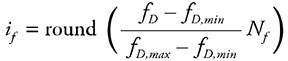
The low information content of the sampled carrier replicas makes them amenable to tabular storage and efficient retrieval. Two tables are required, one each for the sign and magnitude bits. Let i f ∈ {0,1, …, N f – 1} and i θ ∈ {0,1, …, N θ – 1} represent the respective indices into the frequency and phase dimensions of the tables. For each carrier replica segment (typically 1-ms long), a single frequency index is calculated as
 (6)
(6)
where f D is the exact desired frequency and f D,min and f D,max are the minimum and maximum Doppler frequency shifts. The phase index i θ is different for each of the 32-bit words that are strung together to compose the carrier replica segment. Let τ k be the time offset of the midpoint of the kth word in the segment relative to the time of the first sample in the segment. The phase at the midpoint of the kth word is calculated as
![]() (7)
(7)
where θ 0 is the phase of the first sample in the segment, and the modulo operation is modulo 2π. Finally, the phase index of the kth word is calculated as
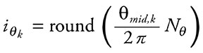 (8)
(8)
To meet precision requirements, the number of indices into the frequency and phase dimensions of the tables were set respectively to N f = 32 and N θ = 256. With this table size, the table-generated carrier replicas are not significantly different from carrier replicas generated by applying the exact phase and frequency values using double-precision computations. The sign and magnitude tables occupy a total of 64 kB in on-chip memory.
- Data Bit Predictor: The GPS L1 navigation data bit sequence {d n,j , d n,j+1 , …} required by the nth spoofer channel is most easily generated in one of two ways. The simplest approach is to pass data bits to the spoofer channels as soon as they can be reliably read off the incoming GPS signals. Naturally, this approach produces a delay in the arrival time of the spoofing data bit as compared to that of the true data bit at the target receiver’s antenna. The delay is most conveniently made an integer number of 1-ms C/A code intervals. Clearly, such a delay is undesirable in a spoofer because a target receiver could be designed to watch for such a delay and thereby detect a spoofing attack.
The second approach is to predict the data bits based on knowledge of the bit structure and a recent bit observation interval. This is the function of the receiver-spoofer’s data bit predictor. This method relies on the fact that the GPS navigation message has a 12.5-minute period and remains nearly perfectly predictable for a period of two hours. In fact, the almanac component of the 12.5-minute data block is refreshed by the GPS Control Segment only once per day, and the remaining data — the individual satellite ephemeris data — can be observed in less than one minute. There are data bit segments within the TLM word of the navigation message that are unpredictable on a regular basis. However, these segments are also unpredictable for the target receiver (in the absence of external data bit aiding). Therefore, the spoofer can simply fill the unpredictable data bit segments with arbitrary data bits and adapt the parity bits and HOW word polarity accordingly.
Discrepancies have been observed between the almanac data of Block IIA and later satellites. For example, the least significant bits of particular ephemeris parameters can differ. This is believed to be a rounding error in early satellites. These discrepancies cause problems with data-bit prediction for Block IIA satellites. The GPS control segment has been alerted to this and is taking corrective measures. Meanwhile, the spoofer module’s data-bit predictor keeps two copies of almanac data: one for Block IIA and one for later satellites.
During a spoofing attack, rising GPS satellites pose a challenge for the data-bit predictor; indeed, for the entire receiver-spoofer. The receiver-spoofer must prevent the target receiver from acquiring bit lock on the new signal until the data-bit predictor has a chance to observe the new satellite’s ephemeris data. This could be done by transmitting a spoofing signal with arbitrary data bits whose boundaries change sporadically by an integer number of C/A code periods.
- Sample-Wise Combiner: Summation of the bit-packed signals generated in each of the spoofer channels is performed sample by sample. The ith sample from the nth spoofer channel is weighted by A n (τ i ) and summed with the corresponding samples from the other spoofer channels, each weighted appropriately. While computationally expensive, sample-wise operations are necessary to generate a combined signal that represents a quantized superposition of the individual spoofing signals with correct relative amplitudes. The composite signal is then re-quantized to 1 or 2 bits before being loaded into the output circular buffer. Re-quantization of the composite signal introduces additional signal distortion, which decreases the carrier-to-noise ratio of each component signal. For 1-bit re-quantization, which is the current configuration, the signal distortion is tolerable until more than eight spoofing signals are combined. More precisely, 1-bit requantization can sustain no more than eight equal-amplitude component signals at a carrier-to-noise ratio of C/N 0 = 48 or higher.
Implementation
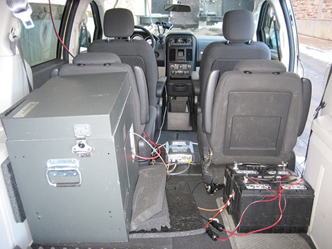
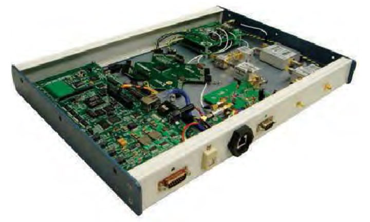
The software-defined receiver-spoofer has been implemented on the Cornell GRID receiver platform (FIGURE 9). Receiver and spoofer software modules run on the same processor.
When tuned for efficiency, the receiver-spoofer meets real-time deadlines with computational resources to spare. At full capability, the receiver-spoofer tracks 12 GPS L1 C/A signals and simultaneously generates 12 spoofing signals, in addition to performing a 1-Hz navigation solution and continuous background acquisition. The 1-bit re-quantization of the composite spoofing signal limits the spoofer module practically to eight component signals. Future versions of the receiver-spoofer may trade computational resources for 2-bit re-quantization, permitting more than eight component spoofing signals.
The marginal computational demands of each tracking and spoofing channel are respectively 1.2 percent and 4 percent of the DSP, the latter value reflecting the high computational cost of carrier replica generation and sample-wise signal combination within the spoofer module.
The core Cornell GRID receiver software is the product of hundreds of developer-hours of work. Developing the spoofer module and extending the core GRID receiver software to include it required a team of three experienced developers working approximately 40 hours apiece, or approximately three developer-weeks. The hardware components of the receiver-spoofer platform shown in Figure 9 are all off-the-shelf components whose total cost is approximately $1,500.
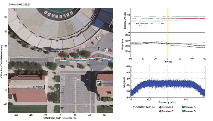
Demonstration Attack
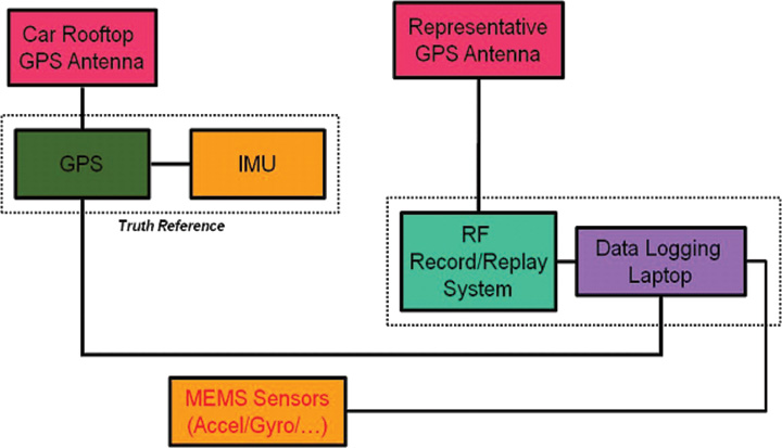
We devised a method for demonstrating a spoofing attack without actually transmitting RF signals at the GPS L1 frequency over the air, which would have violated FCC restrictions on transmitting in a protected band. An interval of digitized authentic GPS L1 C/A code data sampled at 5.7 MHz was stored to disk. The data were input to the receiver-spoofer, which tracked the six GPS signals present, generated corresponding spoofing signals, and combined these into a 1-bit quantized output bitstream. The output bitstream was then combined with the original data by interleaving, and the resulting bitstream was input to a Cornell GRID receiver acting as target receiver, as shown in FIGURE 10.
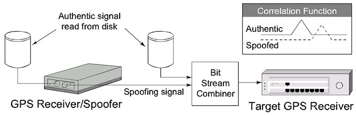
The receiver-spoofer accurately reproduced the code phase, frequency, data-bit values, and relative amplitude of all six GPS L1 signals present. The spoofing signals’ carrier phases, while not designed to match those of the genuine signals, were continuous across accumulation intervals as intended.
To enable observation of the spoofing attack, the target receiver was augmented with correlator taps at 81 different 0.2-chip offsets about the prompt tap, which is nominally aligned with the incoming signal. The amplitude time history from each correlator tap can be combined to produce “footage” of the spoofing attack from the perspective of the individual channels.
FIGURE 11 shows a sequence of frames depicting the attack on one of the channels. The attack lasts approximately 30 seconds. Each successive panel represents a snapshot of the 81 taps’ amplitudes at roughly 6-second intervals. The three red dots represent the delay-lock loop’s tracking points, which continuously attempt to align themselves so that the center point is maximized and the flanking points are equalized. The top frame shows the tracking points nicely aligned on the genuine signal’s correlation peak, while the counterfeit signal’s peak approaches furtively from the right. Of course, in a typical spoofing attack, the counterfeit peak would simply be initially aligned with the genuine peak and initially smaller than the counterfeit peak in the top panel; its approach from the right and large size in the present case is merely for clarity of presentation.
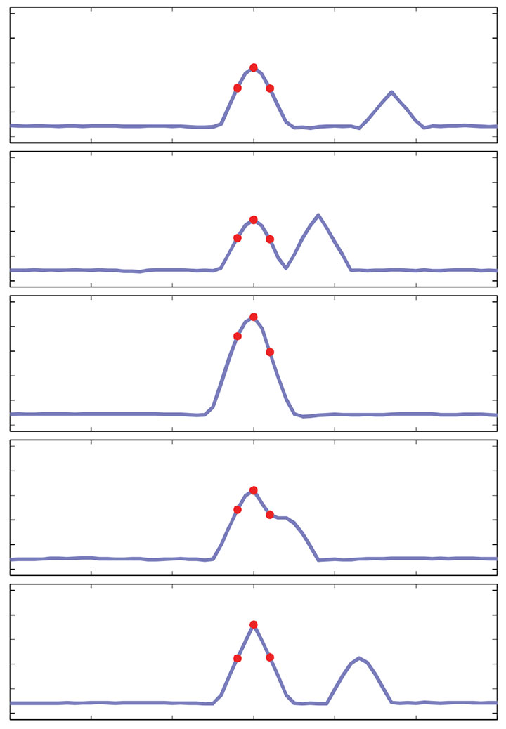
After the spoofed peak aligns with the genuine one, its signal power is gradually increased until it begins to control the tracking points. Eventually, the counterfeit peak drags the tracking points off to the left of the true peak. In the lower two panels of Figure 11, the true peak appears to drift off towards the right because the counterfeit peak has hijacked the 81 taps of the figure’s image zone, which are tied to the victim receiver’s tracking points, and it drags them all leftward relative to the true peak. A sophisticated spoofing attack will attempt right-to-left, or late-to-early, tracking lift-off wherever possible so as to disguise the attack as multipath.
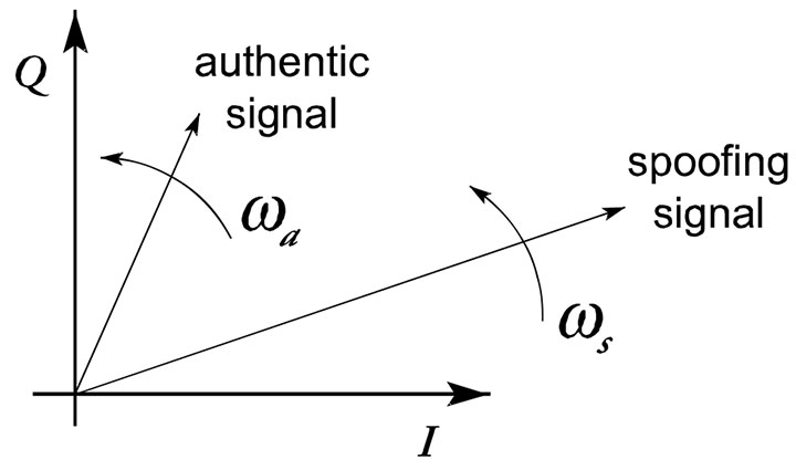
FIGURE 12 illustrates the attack from the perspective of the baseband phasors in the complex plane. In the present version of the receiver-spoofer, no attempt is made to phase-align the authentic and spoofing signals. Consequently, a sign change in the data bit stream is possible as the spoofing phasor’s amplitude gradually increases and the target receiver’s phase-lock loop eventually transitions from tracking the authentic phasor to tracking the spoofing phasor. However, the rotational rates of the two phasors, ωa and ωs in Figure 12, should be nearly equivalent. From Figure 12 it should be apparent that if a receiver-spoofer were capable of phase-aligning with a genuine signal, it could, by transmitting the exact difference between a desired spoofing signal and the true signal at the target antenna, simultaneously produce a spoofing phasor and suppress the authentic phasor. When combined with data-bit prediction, such an attack could be impossible to detect relying solely on user-equipment-based defenses.
Countermeasures
Three spoofing countermeasures have been suggested by work to date. Two of these, both software-defined user-equipment-based defenses, are presented here. These can be thought of as additions to the five user-equipment-based countermeasures presented earlier. The third method, a promising low-impact cryptographic technique, will be disclosed in a separate publication. Neither of the user-equipment-based defenses discussed below is spoofproof; however, each is straightforward to implement and increases the difficulty of mounting a successful spoofing attack.
Data-Bit Latency Defense. The data bit-latency defense is premised on the difficulty of re-transmitting the GPS data bits in real time. The alternative, data-bit prediction, is itself somewhat challenging and is vulnerable to detection at the 2-hour ephemeris update boundaries and when a GPS satellite rises above the horizon.
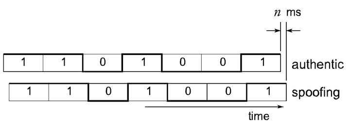
FIGURE 13 illustrates the latency between the spoofing and authentic data bit streams that would arise in the absence of data-bit prediction. To detect this condition, the target receiver has only to continuously monitor bit lock. In other words, the receiver looks for a data-bit sign change between consecutive accumulations at the C/A code-length interval. If a sign change is detected at other than an expected data-bit boundary, then the target receiver raises a flag. Except in unusual circumstances, such as low signal power or ionospheric scintillation, a raised flag betrays a spoofing attack. We have implemented and validated the data-bit latency defense on a modified Cornell GRID receiver.
Besides by data-bit prediction, a spoofer can attempt to counter the data-bit latency defense by jamming until the target receiver loses bit lock and then spoofing during reacquisition. However, as with the time-discrepancy defense, an extended jamming period may be required to sufficiently widen the target receiver’s window of acceptance, and extended jamming is itself telltale evidence of interference.
Vestigial Signal Defense. This defense is premised on the difficulty of suppressing the authentic signal after successful lift-off of the delay-lock loop tracking points. To suppress the authentic signal, a spoofer must transmit the difference between a desired spoofing signal and the true signal at the target antenna. Construction of an effective suppressor signal requires knowledge to within roughly 1/8 of a cycle of each authentic signal’s carrier phase at the phase center of the target antenna. Such precise knowledge of carrier phase implies centimeter-level knowledge of the 3-dimensional vector between the target antenna and the transmitter phase centers. This would be challenging except in circumstances where the receiver-spoofer could be placed in the immediate proximity of the target antenna phase center.
Absent an effective suppressor signal, a vestige of the authentic GPS signal will remain in the input to the target receiver. Soon after lift-off of the delay-lock loop tracking points, the vestige may be well disguised as multipath, but its persistence and distance from the spoofed correlator peak will eventually distinguish the two effects.
To detect the vestigial authentic signal, the target receiver employs the following software-defined technique. First, the receiver copies the incoming digitized front-end data into a buffer used only for vestigial detection. Next, the receiver selects one of the GPS signals being tracked and removes this signal from the data in the buffer. This is the same technique used to remove strong signals in combating the near/far problem in spread-spectrum multiple-access systems, including GPS. Once the tracked signal has been removed, the receiver performs acquisition for the same signal (same PRN identifier) on the buffered data.
These steps are repeated for the same GPS signal and the results are summed non-coherently until a probability of detection threshold is met for some assumed C/N0 value and some desired probability of false alarm. If a significant vestigial signal is present in the data, this technique will reveal it.
Conclusions
The deepening dependence of the civil infrastructure on GPS and the potential for financial gain or high-profile mischief makes civil GPS spoofing a gathering threat. The software-defined receiver-spoofer described here demonstrates that it is straightforward to mount a spoofing attack that would defeat most known user-equipment-based spoofing countermeasures. Moreover, it appears that nothing short of cryptographic authentication can guard against a sophisticated spoofing attack.
With the addition of each modernized GNSS signal, the cost of mounting a spoofing attack rises markedly, and would quickly exceed the capabilities of the GPS L1 civil spoofer demonstrated here. Nonetheless, faster DSPs or FPGAs would make multi-signal attacks possible. Moreover, there will remain many single-frequency L1 C/A code receivers in critical applications for years to come.
It is imperative that more research and funds be devoted to developing and testing practical and effective user-equipment-based civil GPS spoofing countermeasures such as the data-bit latency defense and the vestigial signal defense introduced here. Further research into cryptographic authentication methods should also be pursued. Officials in the U.S. Department of Transportation, the Federal Aviation Administration, and the Department of Homeland Security should consider the perils of civil GPS spoofing and oversee development and adoption of effective countermeasures. Commercial manufacturers of GPS user equipment should adopt at least rudimentary spoofing countermeasures.
In conclusion, consider two security maxims advanced by the Vulnerability Assessment Team at Argonne National Laboratory. The first certainly applies to civil GPS spoofing. One can only hope that the second does not.
Yippee Maxim: There are effective, simple, and low-cost countermeasures (at least partial countermeasures) to many vulnerabilities.
Show Me Maxim: No serious security vulnerability, including blatantly obvious ones, will be dealt with until there is overwhelming evidence and widespread recognition that adversaries have already catastrophically exploited it. In other words, “significant psychological (or literal) damage is required before any significant security changes will be made.”
Acknowledgments
The Cornell GRID receiver development has been funded under ONR grant N00014-04-1-0105. A Reference/Further Reading section will be appended to the version of this article appearing online at env-gpsworld-integration.kinsta.cloud. An earlier version of this article was published in the Proceedings of the September 2008 Institute of Navigation GNSS Conference in Savanna, Georgia.
Manufacturers
The receiver-spoofer consists of a Zarlink/Plessey GP2015 RF front end, a CPLD for signal multiplexing, and a Texas Instruments TMS320C6455 DSP.
TODD E. HUMPHREYS is a research assistant professor in the department of Aerospace Engineering and Engineering Mechanics at the University of Texas at Austin. He received a Ph.D. in aerospace engineering from Cornell University; [email protected].
BRENT M. LEDVINA is an assistant professor in the Electrical and Computer Engineering Department at Virginia Tech. He received a Ph.D. in electrical and computer engineering from Cornell University.
MARK L. PSIAKI is a professor in the Sibley School of Mechanical and Aerospace Engineering at Cornell. He received a Ph.D. degree in mechanical and aerospace engineering from Princeton University.
BRADY W. O’HANLON received a B.S. in electrical and computer engineering from Cornell University,where he pursues a M.S./Ph.D degree.
PAUL M. KINTNER, JR. is a professor of electrical and computer engineering at Cornell. He received a Ph.D. in physics from the University of Minnesota.
References
“Vulnerability assessment of the transportation infrastructure relying on the Global Positioning System,” Tech. rep., John A. Volpe National Transportation Systems Center, 2001.
Key, E. L., Techniques to Counter GPS Spoofing,” Internal memorandum, MITRE Corporation, Feb. 1995.
Scott, L., “Anti-spoofing and authenticated signal architectures for civil navigation systems,” Proc. ION GPS/GNSS 2003,Institute of Navigation, Portland, Oregon, 2003, pp. 1542-1552.
Hein, G., Kneissi, F., Avila-Rodriguez, J.-A., and Wallner, S., “Authenticating GNSS: Proofs against spoofs, Part 1,” Inside GNSS, July/August 2007, pp. 58-63.
Hein, G., Kneissi, F., Avila-Rodriguez, J.-A., and Wallner, S., “Authenticating GNSS: Proofs against spoofs, Part 2,”Inside GNSS, September/October 2007, pp. 71-78.
Scott, L., “Location Assurance,”GPS World,Vol. 18, No. 7, 2007, pp. 14-18.
Stansell, T., “Location Assurance Commentary,”GPS World,Vol. 18, No. 7, 2007, pp. 19.
Warner, J. S. and Johnston, R. G., “GPS spoofing countermeasures,” Dec. 2003, http://www.homelandsecurity.org/bulletin/DualBenefi/warner gps spoofing.html.
Ledvina, B. M., Cerruti, A. P., Psiaki, M. L., Powell, S. P., and Kintner, Jr., P. M., “Performance Tests of a 12-Channel Real-Time GPS L1 Software Receiver,” Proceedings of ION GPS 2003, Institute of Navigation, Portland, OR, 2003.
Ledvina, B. M., Psiaki, M. L., Powell, S. P., and Kintner, Jr., P. M., “Real-Time Software Receiver Tracking of GPS L2 Civilian Signals using a Hardware Simulator,”Proceedings of ION GNSS 2005, Institute of Navigation, Long Beach, CA, Sept. 2005.
Ledvina, B. M., Psiaki, M. L., Powell, S. P., and Kintner, Jr., P. M., “Bit-Wise Parallel Algorithms for E±cient Software Correlation Applied to a GPS Software Receiver,”IEEE Transactions on Wireless Communications, Vol. 3, No. 5, Sept. 2004.
Humphreys, T. E., Ledvina, B. M., Psiaki, M. L., and Kintner, Jr., P. M., “GNSS Receiver Implementation on a DSP: Status, Challenges, and Prospects,”Proceedings of ION GNSS 2006, Institute of Navigation, Fort Worth, TX, 2006.
Warner, J. S. and Johnston, R. G., “A simple demonstration that the Global Positioning System (GPS) Is Vulnerable to Spoofing,”Journal of Security Administration, 2003.
Anon., “ICD-GPS-200C: Navstar GPS Space Segment/Navigation User Interfaces,” Tech. rep., ARINC Research Corporation, 2003, http://www.losangeles.af.mil/library /factsheets/factsheet.asp?id=9364
Borre, K., Akos, D., Bertelsen, N., Rinder, P., and Jensen, S.,A Software-defined GPS and Galileo Receiver: A Single-frequency Approach, Birkhauser, 2007.
Ledvina, B. M.,”Real-Time Generation of Bit-Packed OverSampled Carrier Replicas,” 2008, in preparation.
Johannesson, R. J.,Cross-correlation mitigation in GPS signal acquisition for a real-time software receiver, Master’s thesis, Cornell University, 2007.
Johnston, R. G., “Physical security maxims,” http://www.schneier.com/blog/archives/2008/09 /security maxims.html .