u-blox, Bosch, Geo++ and Mitsubishi Electric are establishing the joint venture Sapcorda Services to bring high-precision GNSS positioning services to mass markets, including autonomous driving.
Bosch, Geo++, Mitsubishi Electric and u-blox have created Sapcorda Services GmbH, a joint venture that will bring high-precision GNSS positioning services to mass-market applications.
The four companies recognized that existing solutions for GNSS positioning services do not meet the needs of emerging high-precision GNSS mass markets.
As a result, they decided to join forces to facilitate the establishment of a worldwide available and affordable solution for system integrators, OEMs and receiver manufacturers. Each partner brings its unique expertise to the joint venture Sapcorda Services.
Sapcorda will offer globally available GNSS positioning services via internet and satellite broadcast and will enable accurate GNSS positioning at centimeter level. The services are designed to serve high-volume automotive, industrial and consumer markets.
The real-time correction data service will be delivered in a public, open format and is not bound to receiver hardware or systems. More information will be made available later this year.
“We believe this initiative with Bosch, Geo++ and Mitsubishi Electric to create Sapcorda Services will bring a truly disruptive GNSS service offering to the market,” said Daniel Ammann, executive VP and co-founder at u-blox. “Key characteristics such as security, safety and mass-scalability, coupled with an attractive business model and an open approach — serving all interested GNSS receiver manufacturers alike — will be a game-changer across a large number of established and emerging applications.”
“We are looking forward to collaborating with our partners in this joint venture,” said Jumana Al-Sibai, member of the executive management of the Chassis Systems Control division of Robert Bosch GmbH. “Together, we want to create a GNSS positioning service that fully supports the requirements for positioning sensors in the automotive sector. Only with built-in safety and the highest levels of precision will we be able to make automated driving reality.”
“Geo++ anticipates defining the future of high precision positioning services with our partners at Bosch, Mitsubishi Electric and u-blox. The combination of the partners’ longstanding leadership in automotive and mass market solutions with Sapcorda’s commitment to push open formats will pave the way for a raft of next generation GNSS applications,” said Gerhard Wübbena founder & president of Geo++.
“Mitsubishi Electric aims to create a border-less global market for high-precision positioning systems where receivers will be able to enjoy real-time correction data services potentially interoperable with the Japanese government’s Centimeter Level Augmentation Service (CLAS) via the Quasi-Zenith Satellite System,” said Masamitsu Okamura, executive officer in charge of Electronic Systems at Mitsubishi Electric Corporation. “We believe that this venture will accelerate adoption of automated driving and safe driving support.”
Three of six new Lockheed Martin-developed state-of-the-art receivers are now deployed to help the U.S. Air Force maintain the accuracy of GPS satellite signals.
In June, the first new Monitor Station Technology Improvement Capability (MSTIC) receiver became operational at Cape Canaveral Air Force Station, Florida. The upgrades continued at U.S. Air Force monitoring stations on the Kwajalein Atoll and Hawaii.
These critical upgrades of the GPS Monitoring Stations from early 1990s technology are part of an overall effort to modernize and maintain the current GPS ground control system, known as the Architecture Evolution Plan Operational Control Segment.
GPS monitoring stations are globally dispersed, fixed-position sites that monitor GPS satellite signals and help maintain their navigation and positioning accuracy for users around the world.
Under Lockheed Martin’s GPS Control Segment (GCS) Sustainment contract, the company used an agile development methodology to develop and deploy the first MSTIC receiver on schedule in under 36 months. The three remaining Air Force GPS Monitoring Stations will be upgraded with MSTIC receivers by the end of 2017.
“Taking advantage of current commercial technology trends has allowed us to provide the Air Force with a monitoring capability that can support the Air Force’s GPS mission for years to come,” said Vinny Sica, vice president and general manager of Mission Solutions for Lockheed Martin. “The MSTIC receiver addresses today’s obsolescence problem while providing the opportunity for the monitoring of modernized navigation signals in the future.”
The new MSTIC receiver’s software-defined radio (SDR) technology will replace the legacy monitor station receiver element (MSRE)’s hardware-based ASIC (application-specific integrated circuit) platform originally deployed almost two decades ago, Sica said.
MSTIC leverages commercial off-the-shelf hardware without the need for custom firmware. Standard interfaces and the inherent configurability of the architecture simplifies sustainment and enables MSTIC software to migrate to new hardware platforms as commercial vendors increase processing power, improve reliability and enhance cybersecurity, Sica said.
“MSTIC’s new SDR technology enables the remote application of mission specific software updates which will improve performance and enable reception of modernized GPS signals,” added Sica.
The GPS Directorate at the U.S. Air Force Space and Missiles Systems Center contracted the MSTIC upgrade. Air Force Space Command’s 2nd Space Operations Squadron (2SOPS), based at Schriever Air Force Base, Colorado, manages and operates the GPS constellation for both civil and military users.
Gen. David L. Goldfein, chief of staff of the Air Force, listens to 1st Lt. Mark Skinner, 2SOPS GPS mission commander, explain current 2SOPS activities during his visit to Schriever AFB Dec. 20, 2016. (U.S. Air Force photo/Christopher DeWitt)
Companies and organizations like Spirent Federal Systems share their products and insights in the exhibit hall. (Photo: ION)
The ION GNSS+ 2017 conference and industry exhibition covers all aspects of satellite navigation technology. It takes place Sept. 25–29 at the Oregon Convention Center in Portland.
The theme this year is “GNSS + Other Sensors in Today’s Marketplace.”
The conference will feature two tracks:
“Applications and Advances” focuses on safety of life, commercial and mass-market applications, and GNSS plans and policies.
The second track, “Research and Innovations,” will concentrate on autonomous systems, multi-sensor applications and advanced GNSS algorithms.
Short Courses taught by Internationally Recognized Leaders
This year, ION is introducing complimentary Short Courses to be taught by internationally recognized GNSS experts and educators throughout the day on Monday, Sept. 25.
Short Courses are designed to enhance the ION GNSS+ attendee experience while giving everyone an opportunity to learn from the rock stars in the field, according to ION’s Executive Director, Lisa Beaty.
Presented in a lecture-style learning environment, the Short Courses are designed for professionals at any level of their career, for engineers and academics as well as the non-engineer wanting to boost their knowledge base in a particular area (such as members of the sales team).
The Short Courses will taught by internationally recognized GNSS experts and educators. These instructors are masters in their field, the people who developed the technology and “wrote the textbooks.”
The Short Courses are complimentary to all registered ION GNSS+ 17 attendees.
Courses include:
GNSS 101: An Introduction
Fundamentals of GNSS Receiver Design
Precise Time and Time Interval (PTTI) Services from GPS and GNSS Systems
Image-Aided Navigation
Assisted GNSS (A-GNSS)
Resilient Position Navigation and Time
A Practical Introduction to GNSS/INS Integration
Nonlinear Estimation Techniques for Navigation Systems
Kalman Filter Applications to Integrated Navigation 1 and 2, James L. Farrell / Frank van Graas
Introduction to Multi-Constellation GNSS Signals, John Betz
Raw GNSS Measurements from Android Phones: Theory and Application, Wyatt Riley / Steve Malkos / Mohammed Khider
GNSS Error Characterization, Analysis and Mitigation, Chris Bartone
Plenary Session: Sept. 26, 6:30–8:30 p.m.
Featuring Stan Honey, yacht racing navigator, Emmy-winning developer of TV graphics, engineer in navigation and remote sensing.
Also featuring Carla Bailo, assistant vice president for Mobility Research and Business Development, The Ohio State University, speaking on smart mobility, smart cities and the importance of GIS in the Internet of Things.
Figure 1. Galileo constellation and occupation status of orbital slots (RAAN: right ascension of the ascending node, May 9, 2017). (Source: ESA)
What to Expect with the Current Constellation
This article demonstrates the benefits of Galileo integration for high-precision real-time kinematic (RTK) through representative case studies, considering baseline length, multipath impact and tree canopy.
The results confirm usability of the current Galileo constellation in high-precision RTK applications and show improved availability, accuracy, reliability and time-to-fix in difficult measuring environments.
Plus, Galileo-only RTK positions are compared with GPS-only and GLONASS-only solutions.
By Xiaoguang Luo, Jun Chen and Bernhard Richter, Leica Geosystems AG
Until now, based on simulated and observed data, the benefits of Galileo (FIGURE 1) for high-precision RTK have been investigated in single-base RTK and network RTK solutions. Building on the results of previous studies that frequently employed theoretic analysis and simulation, we present the benefits of Galileo for high-precision RTK based on real observations from the current Initial Operational Capability (IOC) satellite constellation. Using up-to-date real-time corrections including Galileo, we analyze the performance of network RTK under different measuring conditions with respect to availability, accuracy, reliability and time-to-fix.
To achieve the maximum inter-operability with other GNSS con-stellations, all the Galileo signals in the E1 and E5 band, i.e. E1, E5a, E5b and AltBOC (alternative binary offset carrier), are used for positioning in the latest proprietary firmware and receivers (see “Manufacturers” section for details).
The Galileo E1 signal is overlapped with the GPS L1 signal at a center frequency of 1575.420 MHz, whereas the Galileo E5a and GPS L5 signals are overlapped at 1176.450 MHz. As far as BeiDou is concerned, the E5b frequency of Galileo corresponds to the B2 frequency of BeiDou-2 at 1207.140 MHz.
The AltBOC signal is also supported in order to benefit from its superior performance in multipath suppression. The availability of more than two frequencies is beneficial for ionospheric modeling, which plays an important role in ambiguity resolution on the fly.
In addition, multi-frequency RTK provides more immunity to temporary interruption of GNSS signals caused by interference or by site-specific effects like multipath. When forming linear combinations, the incorporation of multi-frequency signals enhances flexibility and robustness, where the mathematical correlations introduced by including the same signal in different linear combinations of the same type need to be handled properly in RTK algorithms.
By enabling the tracking of Galileo satellites in the aforementioned firmware, the Galileo signals will be used in different RTK position types by default, including navigation position, phase-aided differential code position, extended RTK (xRTK) position and RTK fixed position. When compared to a standard RTK fix, an xRTK fix is provided at a slightly lower accuracy level, but with higher availability in difficult environments such as urban canyons and dense canopy.
In terms of RTK correction data formats, Galileo is included in the standardized RTCM v3 MSM format and in the proprietary 4G format. To use Galileo in network RTK, the real-time products provided by network correction services need to include Galileo as well. In the latest version of a proprietary GNSS network software, Galileo is used in network processing to provide RTK corrections via the individualized master-auxiliary (iMAX) method and the virtual reference station (VRS) method in the RTCM 3.2 MSM formats.
RTK PERFORMANCE CHARACTERISTICS
Multi-constellation and multi-frequency GNSS RTK is a complex real-time process, aiming to provide cm-level positioning accuracy with as few as possible data epochs for variable user kinematics and even in difficult measuring environments. Therefore, RTK performance characteristics need to be carefully selected to be able to evaluate the system as a whole and to address users’ concerns in their applications.
The following parameters are used in this article to assess the benefits of Galileo for high-precision RTK:
Satellite usage. Number of satellites used in RTK fixed solutions with an elevation cut-off angle of 10°;
Availability. Percentage of RTK fixed positions relative to all positions obtained during a time period;
Accuracy. Deviation of RTK fixed positions from ground truth with a higher degree of accuracy, where the ground truth can be determined by means of a total station or by post-processing long-term GNSS data;
Reliability. Percentage that the position error (with respect to ground truth) is less than 3 x coordinate quality (CQ) indicator;
Time to Fix. Time needed to regain an RTK fixed solution after losing ambiguity fix provided that GNSS signal tracking is not interrupted.
OPEN-SKY CASE STUDY
The open-sky case study was performed in the Heerbrugg testbed. Two receivers were connected to a single antenna via a four-way antenna splitter. One receiver received four-system iMAX corrections in the RTCM v3 MSM format over a short baseline of 2 km, whereas the other received RTK data of the same type over a long baseline of 116 km. By considering different baseline lengths, the open-sky experiment focused on the usability of the current Galileo constellation in GNSS RTK under normal conditions. Two days of 1-Hz GNSS data were investigated with respect to satellite usage and positioning accuracy.
Using different combinations of GNSS to analyze the short baseline data — GPS+GLO (GG), GPS+GLO+BDS (GGB) and GPS+GLO+GAL+BDS (GGGB) — the mean numbers of used satellites are 15, 17 and 20, respectively, where the elevation cut-off angle was set to 10°. On average, three Galileo satellites contribute to RTK fixed solutions.
For the four-system combination GGGB, Figure 2 shows the satellite usage for each individual system over the two-day period. It can be seen that for a short baseline of 2 km, a maximum number of four Galileo satellites can be used for positioning. In fact, during 80.3% of the whole test period, the number of Galileo satellites used in RTK fixed solutions is equal to or greater than the number of BeiDou satellites used.
Figure 2. Number of satellites used in RTK fixed positions with GGGB under open sky (iMAX, RTCM v3 MSM, baseline length: 2 km, GGGB: GPS+GLO+GAL+BDS, DOY: day of year).
Table 1 provides statistics on Galileo satellite usage in case of GGGB for different baseline lengths. As would be expected, the number of Galileo satellites used decreases with an increasing baseline length. In approximately 41% of the cases, three Galileo satellites are used in the short baseline test, whereas two Galileo satellites are used in the long baseline test.
Moreover, the probability that no Galileo satellites are involved in a four-system combined solution grows significantly from 1.9% to 15.0% as the baseline length increases from 2 km to 116 km. The probability that only one Galileo satellite is used under open sky is relatively small, amounting to around 0.5%. This is reasonable since no benefits for high-precision RTK are expected in this particular situation. Regarding the short baseline case, there is a 97.7% probability that at least two Galileo satellites are used for positioning, whereas this probability decreases to 84.4% in the long baseline case.
Table 1. Probability [%] that n Galileo satellites are used in RTK fixed positions with GGGB during the two-day period of the open-sky experiment (iMAX, RTCM v3 MSM, GGGB: GPS+GLO+GAL+BDS).In terms of positioning accuracy, Figure 3 compares the 3D errors from analyzing the long baseline data with different GNSS constellations. Regarding the entire two-day period illustrated in Figure 3a, the integration of BeiDou (GG vs. GGB) and Galileo (GGB vs. GGGB) results in higher position repeatability with more consistent errors. For a selected period of 12 hours, Figure 3b highlights the advantages of Galileo in reducing large 3D errors from 6–8 cm to 3–4 cm, where two or three Galileo satellites are used in case of GGGB.
Figure 3. 3D errors of RTK fixed positions under open sky (iMAX, RTCM v3 MSM, baseline length: 116 km, GG: GPS+GLO in green, GGB: GPS+GLO+BDS in blue, GGGB: GPS+GLO+GAL+BDS in red, DOY: day of year) (a) Entire two-day period, (b) Selected 12-hour period (28–40 h).
MULTIPATH CASE STUDY
In this case study, a GNSS smart antenna was set up in a location with strong multipath effects, where GNSS signals were obstructed and reflected by the surrounding buildings (Figure 4). This test setup simulates the use case that a user measures a point near a building with degraded GNSS signal reception, even at high elevation angels.
Figure 4. Test setup in a strong multipath environment in Heerbrugg (rover: GS16, antenna height: 1.8 m) (a) View from the south, (b) View from the north.
The default elevation cut-off angle of 10° was applied. The receiver received four-system VRS corrections in the RTCM v3 MSM format, where the distance to the physical reference station was approximately 200 m. Three hours of 1-Hz GNSS data were analyzed with respect to accuracy, reliability and time to fix.
Figure 5 illustrates the 3D errors from multi-GNSS RTK with and without Galileo (GGGB vs. GGB), along with the number of used satellites. Regarding the periods marked with dashed rectangles, the inclusion of two or three Galileo satellites (Figure 5b) leads to significant improvements in positioning accuracy at the few cm to dm level (Figure 5a). By comparing the empirical cumulative distribution function (CDF) of the 3D errors, the probability that 3D error is within 5 cm increases from 70% to 85% if Galileo is used, even with a maximum number of three satellites.
Figure 5. Impact of Galileo integration on RTK positioning accuracy under strong multipath (VRS, RTCM v3 MSM, GGB: GPS+GLO+BDS in blue, GGGB: GPS+GLO+GAL+BDS in red, DOY: day of year) (a) 3D errors of RTK fixed positions, (b) Number of used satellites (Galileo in green).
Tables 2 and 3 provide the root mean square (RMS) errors and reliability of RTK fixed positions from the multipath experiment, respectively. By using Galileo in high-precision RTK, the 3D RMS error is significantly reduced by 56.3% in this case study, from 0.080 m (GGB) to 0.035 m (GGGB). When compared to the horizontal components, the height RMS error shows a larger relative improvement of 58.7% due to Galileo integration. The reliability reflects the consistency between the actual position error with respect to ground truth and the CQ indicator estimated based on mathematical models in RTK algorithms. As shown in Table 3, the 3D reliability improves by 7.3%, from 88.2% (GGB) to 95.5% (GGGB), where the increases for the horizontal components and height are comparable.
Table 2. Root mean square errors [m] of RTK fixed positions under strong multipath (VRS, RTCM v3 MSM, GGB: GPS+GLO+BDS, GGGB: GPS+GLO+GAL+BDS).Table 3. Reliability [%] of RTK fixed positions under strong multipath (VRS, RTCM v3 MSM, GGB: GPS+GLO+BDS, GGGB: GPS+GLO+GAL+BDS).The time to fix (TTF) was determined by constantly re-initializing RTK once an ambiguity fix was gained. During the whole period of repeatedly resetting the RTK filter, the GNSS signals were tracked continuously without interruption. A total of 765 TTF values were obtained with GGB, whereas 1,128 TTF estimates were available with GGGB. The significantly larger number of the TTF samples from GGGB indicates higher availability of RTK fix if Galileo is used.
Figure 6 shows the statistical distribution of TTF with respect to Galileo integration. As can be seen in the empirical CDF in Figure 6a, it takes shorter time for GGGB to regain an ambiguity fix. As an example, GGGB allows ambiguity resolution within 5 s (10 s) with 46% (87%) probability, which is 29% (16%) higher than GGB. Regarding the boxplots of TTF in Figure 6b, GGGB shows a smaller median (by 25% from 8 s to 6 s) and a smaller interquartile range (IQR; by 50% from 4 s to 2 s) than GGB, where the IQR is the length of the box. This indicates that the integration of Galileo enables a faster ambiguity resolution with more consistent fixing performance.
Figure 6. Impact of Galileo integration on time to fix (TTF) statistics under strong multipath (VRS, RTCM v3 MSM) (a) Empirical cumulative distribution function (CDF) of TTF, (b) Boxplot of TTF with median and interquartile range (IQR).
CANOPY CASE STUDY
In this case study, a receiver was connected to an antenna under tree canopy (Figure 7), where GNSS signals are blocked, attenuated and reflected, leading to decreased number of observations, low data quality and degraded RTK performance.
Under these circumstances, the inclusion of Galileo satellites transmitting multi-frequency signals could be particularly beneficial for high-precision RTK. Using an elevation cut-off angle of 10°, the receiver received four-system iMAX corrections in the RTCM v3 MSM format, where the baseline length was 116 km. A long baseline was intentionally selected as an additional challenge for the RTK system. About seven hours of 1-Hz GNSS data were investigated regarding availability, accuracy and reliability.
Figure 7. Test setup under canopy in Heerbrugg (rover: GS10, antenna: AS10).
Figure 8 illustrates the impact of Galileo integration on RTK availability and accuracy under canopy, along with the number of used satellites. As can be seen in Figure 8a, the inclusion of Galileo improves the availability of RTK fixed positions by 12.2%, from 65.7% (GGB) to 77.9% (GGGB). Moreover, dm-level position errors are largely reduced, as shown in FigURE 8c. The improvements in availability and accuracy are achieved by using up to three Galileo satellites (Figure 8b). This demonstrates that the current Galileo constellation in the IOC phase brings considerable benefits to high-precision RTK under canopy conditions.
Figure 8. Impact of Galileo integration on RTK availability and accuracy under canopy (iMAX, RTCM v3 MSM, baseline length: 116 km, GGB: GPS+GLO+BDS in blue, GGGB: GPS+GLO+GAL+BDS in red, DOY: day of year) (a) Availability of RTK fixed positions over time, (b) Number of used satellites (Galileo in green), (c) 3D errors of RTK fixed positions.
Tables 4 and 5 provide the RMS errors and reliability of RTK fixed positions from the canopy experiment, respectively. The main factors degrading the RTK accuracy in this case study are not only the canopy environment, but also the long baseline length of 116 km. It can be seen in Table 4 that the integration of Galileo leads to a significant reduction of 3D RMS error by 23.7%, from 0.114 m (GGB) to 0.087 m (GGGB).
By comparing the 2D and 1D RMS errors, the benefits of Galileo for the height are more dominant than for the horizontal components, which was also observed in the multipath experiment (Table 2). In terms of reliability, only slight (below 2%) increases are visible in Table 5. 116km baseline length and heavy canopy are considered extreme conditions and beyond the standard conditions relevant for specifications. Considering reliability together with availability (Figure 8a), it is encouraging to see that both the RTK performance characteristics are improved in this case study.
Table 4. Root mean square errors [m] of RTK fixed positions under canopy (iMAX, RTCM v3 MSM, baseline length: 116 km, GGB: GPS+GLO+BDS, GGGB: GPS+GLO+GAL+BDS).Table 5. Reliability [%] of RTK fixed positions under canopy (iMAX, RTCM v3 MSM, baseline length: 116 km, GGB: GPS+GLO+BDS, GGGB: GPS+GLO+GAL+BDS).
GALILEO-ONLY RTK
To optimize the performance of multi-GNSS RTK positioning, the individual systems need to be fully understood and mastered. With a previous firmware release in August 2014, mass-market devices were able to perform GLONASS-only and BeiDou-only high-precision RTK. In 2014 tests, we compared the performance of GPS-only, GLONASS-only and BeiDou-only RTK at different accuracy levels. Considering that Galileo has reached the IOC phase, it is reasonable to assess the Galileo-only RTK performance with the latest firmware.
Due to the limited number of usable Galileo satellites, Galileo-only RTK positioning was carried out in the Heerbrugg open-sky testbed over a very short baseline of 1 m. In addition, the elevation cut-off angle was set to 0° in order to track as many Galileo satellites as possible simultaneously. Two receivers were connected to two choke-ring antennas with good low-elevation tracking ability. Single-base RTK positioning was performed with four-system corrections in the RTCM v3 MSM format. About one hour of 1-Hz GNSS data was analyzed with a special focus on positioning accuracy.
Figure 9 shows the 3D errors from GPS-only, GLONASS-only and Galileo-only RTK positioning, where the numbers of used satellites are 8–11, 7–9 and 5–6, respectively. During the test period, only three or four BeiDou satellites were tracked with poor geometry, making BeiDou-only RTK impossible. As the figure shows, the 3D errors from GPS-only and Galileo-only RTK are at a comparable level with similar RMS values, whereas the 3D RMS error from GLONASS-only RTK is almost twice as large as the GPS/Galileo-only case. Note that when compared to GPS-only RTK, almost half as many satellites are used in Galileo-only RTK.
Figure 9. 3D errors of RTK fixed positions from GPS-only, GLONASS-only and Galileo-only RTK under open sky (single-base RTK, baseline length: 1 m, RTCM v3 MSM, DOY: day of year, RMS: root mean square).
Figure 10 displays the statistical distribution of the 3D errors from GPS-only, GLONASS-only and Galileo-only RTK positioning. Regarding the empirical CDF in Figure 10a, GPS/Galileo-only RTK shows a clearly more favorable error distribution than the GLONASS-only case. Using only GPS or Galileo, the probability that 3D error is within 1 cm is above 80%, which is approximately 30% higher than using only GLONASS. For 3D errors ranging between 5 mm and 1.7 cm, Galileo-only RTK even provides a slightly higher cumulative probability than the GPS-only case. The 3D error boxplots in Figure 10b illustrate a similar pattern between GPS-only and Galileo-only RTK, which is superior to GLONASS-only RTK due to the significantly smaller median and IQR.
Figure 10. 3D error statistics from GPS-only, GLONASS-only and Galileo-only RTK under open sky (single-base RTK, baseline length: 1 m, RTCM v3 MSM). (a) Empirical cumulative distribution function (CDF) of 3D errors, (b) Boxplot of 3D errors (IQR: interquartile range).
CONCLUSIONS
With the declaration of Galileo Initial Services in December 2016, for the first time ever all GNSS users worldwide are able to use the positioning, navigation and timing information provided by Galileo’s global satellite constellation. Upon full system completion by 2020, Galileo will play an important role in high-precision GNSS applications for users around the world. This article showed representative case studies to understand the benefits of the current Galileo constellation for high-precision RTK. In addition to a multi-GNSS solution, the performance of Galileo-only RTK was presented. The main findings from the case studies can be summarized as follows:
In the open-sky test, with an elevation cut-off angle of 10°, on average three Galileo satellites can be used for high-precision multi-GNSS RTK. This leads to cm-level improvements in coordinate repeatability over a long baseline of 116 km.
In the multipath case study, the additional use of two or three Galileo satellites produces significant enhancements in positioning accuracy at the few cm to dm level, where the benefits for the height component are more significant. Moreover, the integration of Galileo increases the 3D reliability of RTK fixed positions by 7.3% and reduces the median time to fix by 2 s (25%).
In the canopy experiment, the inclusion of Galileo improves the availability of RTK fixed solutions by 12.2%. Furthermore, dm-level position errors are largely reduced.
When compared to GPS-only RTK, Galileo-only RTK provides a similar positioning accuracy over a 1-m baseline under open sky, where almost half as many satellites are used. The 3D RMS error from GLONASS-only RTK is approximately twice as large as the GPS/Galileo-only case.
The promising results achieved through Galileo integration already indicate the very important role of the European GNSS in high-precision, multi-frequency and multi-constellation RTK positioning. During the deployment of the Galileo system, more benefits can be expected in the near future.
ACKNOWLEDGMENTS
The staffs of Leica Geosystems AG (Heerbrugg/Switzerland), Christian Waese and Youssef Tawk, are gratefully acknowledged for support in setting up the variety of RTK network streams.
MANUFACTURERS
SmartWorx 6.16 of Leica Viva GNSS is the latest firmware cited and used in these high-precision RTK tests. Leica GNSS Spider 7.0.0 furnished the GNSS real-time corrections. The open-sky case study used two Leica Viva GS10 units connected to a Leica Viva AS10 antenna via a four-way antenna splitter. The multipath case study used a Leica Viva GS16 GNSS smart antenna. The canopy case study used a Leica Viva GS10 receiver and a Leica Viva AS10 antenna. The Galileo-only RTK test used two Leica Viva GS10 receivers and two Leica AR25 choke ring antennas.
Harris Corporation has delivered the third of 10 advanced navigation payloads to Lockheed Martin, which will increase accuracy, signal power and jamming resistance for U.S. Air Force GPS III satellites.
The navigation payload before integration into the second GPS III SV, which now is in environmental testing. (Photo: Harris)
The advanced navigation payloads feature a Mission Data Unit (MDU) with a unique 70-percent digital design that links atomic clocks, radiation-hardened computers and powerful transmitters — enabling signals three times more accurate than those on current GPS satellites.
The new payloads also boost satellite signal power, increase jamming resistance by eight times and help extend the satellite’s lifespan.
The payload is expected to be integrated into GPS III Space Vehicle 3 (GPS III SV03) this summer. In May, Harris’ second GPS III navigation payload was integrated into GPS III SV02.
The first navigation payload is integrated aboard GPS III SV01, which has now completed rigorous testing and is in storage awaiting its expected 2018 launch.
The MDU performs the primary mission of the GPS satellite, which is generation of the navigation signals and data that provide precise time information to users on a continuous basis. (Photo: Harris)
“We are now in full production and on target to deliver the fourth GPS III navigation payload to Lockheed Martin this fall,” said Bill Gattle, president, Harris Space and Intelligence Systems. “Our payloads help U.S. and allied soldiers complete their missions, enable billions of dollars in commerce and benefit the everyday lives of millions of people around the world.”
Harris has a long legacy of expertise in creating and sending GPS signals, extending back to the mid-’70s — providing navigation technology for every U.S. GPS satellite ever launched.
Harris is also developing a fully digital MDU for the U.S. Air Force’s GPS III Space Vehicles 11+ acquisition. This new MDU will be demonstrated in fall 2017 and provides even greater flexibility, affordability and accuracy versus existing GPS satellites.
Harris navigation payloads are already integrated in the second GPS III space vehicle, now in environmental testing, and the first GPS III satellite (pictured here), expected to launch in 2018. (Photo courtesy Lockheed Martin)
In the battle for reliable positioning and timing, the U.S. Army is engaged in a multitude of activities, including mounted and dismounted A-PNT (assured position, navigation and timing) systems, anti-jam technology and pseudolites.
The idea is simple: Take some GPS satellites, and put them on or near the ground. Now you have a navigation system where you have full control over the locations and power of the transmissions. You can ensure that the transmissions reach places that GPS normally struggles with, such as deep urban canyons, forests and valleys.
You can turn up the transmit power, so they are much harder to jam than spaceborne GPS signals. These pseudo-satellites, commonly referred to as pseudolites, have seen steady interest over the years for a variety of applications.
Now the U.S. Army is pursuing the use of pseudolites as part of its initiative to maintain operation in GPS-denied environments.
Pseudolite Basics
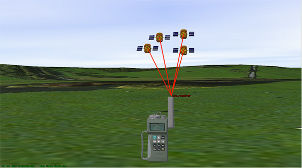
There are various types, and use-cases, of pseudolites. In this column we’ll consider the direct-ranging pseudolite, which can be simply considered as a ground-based GPS satellite. If we deploy several pseudolites on the ground, we can imagine that a normal GPS receiver would be able to receive the GPS-standard transmissions and derive a position, just as we would from the space-based satellite transmissions.
The fact that the pseudolites are ground-based introduces us to the first consideration: The locations of the transmitters are no longer described by orbital parameters. Instead of calculating the position of satellites, we need to describe the location of the pseudolites in geographical terms, perhaps with a fixed position described in Earth-centered, Earth-fixed (ECEF) coordinates.
The transmitted navigation data message, which would normally contain almanac and ephemeris information, may now need to contain the geographical position of the pseudolite. Not a problem, but our GPS receivers will need a software upgrade to be able to handle this situation.
The deployment of the pseudolites themselves poses an interesting problem. Imagine a military scenario, where the army is deployed to a region of interest. Navigation warfare is taking place, and GPS is frequently jammed in the region.
High-power pseudolites are deployed to allow the army to navigate despite the jamming, using the same standard-issue GPS receivers that soldiers are familiar with.
The first problem is, having placed your pseudolites in position, how do you know where they are?
You might choose to place your pseudolites at locations that have previously been surveyed, so you know where they are in advance. But this isn’t likely, particularly if you’ve just moved your troops into an unfamiliar area. You might also want to move the pseudolites regularly, as the army moves to new ground. So the pseudolites need to determine their own position, and the easiest way for at pseudolite to determine its own position is with GPS, of course.
Isn’t this a bit incestuous? If we’re using pseudolites because GPS is jammed, how does the pseudolite get its position? This is why military pseudolites will typically be fitted with some form of anti-jam technology, such as a controlled radiation pattern antenna. This allows the pseudolite to receive GPS satellite signals in the presence of jamming, determine its own position, and transmit that as part of its own navigation message.
So, now that we can get pseudolite locations, the next consideration is: Where should pseudolites be placed?
A-DOP-ting a Good Layout
If you know about GNSS, you’ll be familiar with the concept of dilution of precision (DOP). This is essentially a measure of how accurate your position estimate is likely to be, due to the geometry of the satellites: a good wide spread of satellite positions gives us better accuracy.
Figure 1. Poor satellite geometry, resulting in high DOP. (Image: Michael Jones)Figure 2. Good satellite geometry, resulting in low DOP. (Image: Michael Jones)
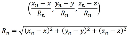
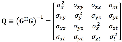
The DOP can be easily calculated by forming a covariance matrix of the geometry, expressed in an appropriate coordinate frame. If (xn, yn, zn) denotes the position of the nth pseudolite, and (x, y, z) the position of the receiver, we can express the unit vectors from the receiver location to the pseudolite location:
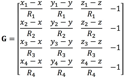
We then form a matrix of these unit vectors:
Finally, we form the covariance matrix from which we can extract the DOP values:
From the elements of this matrix we can determine the various DOP metrics. Let’s concentrate on horizontal DOP (HDOP), given by:
When positioning using GPS satellites, we are blessed with a Walker constellation that generally gives us a nice spread of satellite locations (unless we’re in an urban canyon). On the battlefield, using pseudolites, we do not have the same luxury.
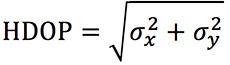
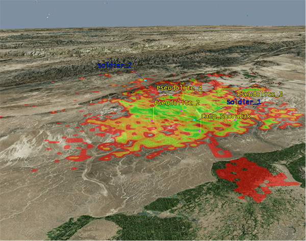
Let’s consider a scenario: a conflict in Helmand province, Afghanistan. An operating base is established at Camp Shorabak, where a pseudolite is operating, and three further pseudolites are deployed in the field. This is shown in figure Figure 3.
Figure 3. Scenario with four pseudolites. (Image: Michael Jones)
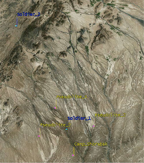
Taking a look at Figure 4, we can see what this means for HDOP. The regions shaded green represent locations where our HDOP is less than 2.5, and the red areas represent an HDOP greater than 50.
Soldier #1 is surrounded by the four pseudolites, which is a pretty nice arrangement: We get an HDOP of around 2.4. But if we now consider soldier #2, located a bit further out, we get a very different picture.
Here we have an HDOP of 64, which is fairly terrible. It’s not really that surprising looking at the geometry — to soldier #2 the pseudolites all appear in a similar direction. Soldier #2 cannot expect to achieve good positional accuracy in this arrangement.
Figure 4. HDOP for the Afghanistan scenario. (Image: Michael Jones)
So getting a good geometric spread of ground-based pseudolite locations could be a bit of a challenge, especially if the operating area is constantly moving and changing. The next thing to think about is getting enough height.
Getting the Height Right
When we perform positioning using GPS, we typically track several satellites, which have a range of elevations. Many GPS receivers will choose to ignore the satellites at low elevations, such as those within 5 degrees of horizontal, because those satellites are generally the least reliable. They may be partially obscured, and subject to more noise and fading.
Ground-based pseudolites all have very low elevations by definition. Unless the terrain is perfectly flat and smooth, pseudolites quickly become obscured. Even with flat ground, pseudolite signals will disappear behind the horizon after a few kilometers.
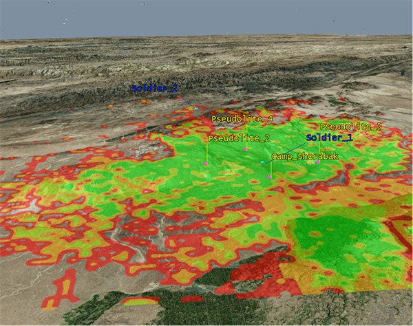
Let’s go back to our Afghanistan scenario again. This time, instead of looking at DOP, let’s look at the geographical coverage of our four pseudolites. Here we’ll assume that our user, the soldier, is 2 meters (m) high, and the pseudolite antennas are mounted at a height of 20m above the ground. That’s pretty high — the army will need to erect some masts.
Figure 5 shows what we get. The green areas are locations where our soldier can see all four pseudolites; yellow three, orange two, and red one. At all other locations, no pseudolite signals can be seen at all. You can quickly see that the range isn’t great — terrain, even small undulations in the ground, is a line-of-sight killer. Add some buildings and trees and the situation gets worse. Reduce the height of our pseudolites below 20m, and the situation gets worse. Soldier #1 can receive three pseudolite signals, but soldier #2 has no hope in this case.
Figure 5. Pseudolite visibility at 20m antenna height. (Image: Michael Jones)
Let’s raise the height of the antennas to a fairly crazy 100m above ground (Figure 6). As expected, we get much better coverage, but soldier #2 still has a problem. To get good signal coverage over any sizable area, you really do need to get those antennas as high as possible.
Figure 6. Pseudolite visibility at 100-m antenna height. (Image: Michael Jones)
Augmenting GPS
Often, we don’t want to rely on pseudolite signals alone. If GPS is available, we clearly want to make use of it, and so we want to use a mixture of both GPS satellites and pseudolites. Consider working in a region of sporadic GPS reception, such as an urban environment or forest. We can usually receive a couple of good GPS satellites, but we also need a couple of pseudolites to help us get a complete navigation solution.
Coming back to one of our original objectives, which is to avoid redesigning the GPS receiver hardware, we need to make sure that our receivers can receive and process both GPS satellite signals and pseudolite signals simultaneously. To achieve this, we can decide to make our pseudolites transmit GPS-standard signals, and make use of unassigned spreading codes to essentially create new satellites in the constellation.
But we quickly run into a problem. GPS satellites are always a distance of around 20,000 kilometers away, and the received signal strength is also fairly constant: around –158.5 dBW. This is a very small signal, as we all know, sitting well below the noise floor. When we suddenly bring high-power pseudolites into the mix, we have quite a nasty problem to deal with.
Near, Far, Wherever You Are
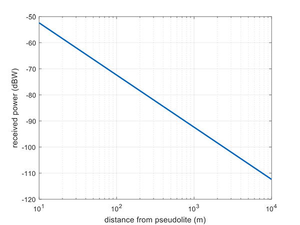
Let’s say, for argument’s sake, we have a pseudolite transmitting with a power of 1 watt. Conducting a basic link budget analysis gives us the plot below and suggests that, at a distance of 10 km from the pseudolite, we can expect to receive the signal at around –112 dBW. This is way above our GPS satellite signal level, but might be manageable by a receiver. Now consider a receiver at a distance of 100 m from the transmitter: we receive a power of –72 dBW, which is huge.
In our quest to augment GPS and make it more robust, we have in fact created a GPS jammer, and achieved exactly the opposite. As with any radio communications link, the received power is extremely sensitive to the distance (varying with the square of distance). In pseudolite terminology, this is known as the near/far problem.
Figure 7. Theoretical received power for a 1-W pseudolite, under ideal conditions. (Figure: Michael Jones)
The near/far problem has given engineers headaches for quite some time. Essentially, the problem comes down to: How can our GPS receivers handle such a massive dynamic range of expected signals? Especially if our objective is to avoid modifying the GPS receiver hardware, if at all possible.
How can a receiver handle the high power of a close-up pseudolite, which is to all intents a jammer, whilst simultaneously receiving the tiny GPS satellite signals from space? Various solutions have been proposed over the years, but one of the current favorite techniques involves pulsing the pseudolite signal.
The idea, then, is to only turn on the pseudolite periodically, essentially applying a duty cycle to the transmission. If a pseudolite isn’t transmitting, it can’t interfere with the normal GPS signals. There are a couple of things to take into consideration here:
What should the pulse duty cycle be, to enable both satellites and pseudolites to be tracked?
How does the GPS receiver behave when presented with alternating large and small signals?
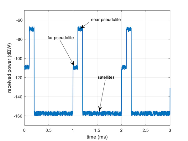
A mathematical analysis of duty cycle effects is beyond the scope of this column, but consider Figure 8 for a qualitative view. Here we have two pseudolites operating alongside GPS satellites. The duty cycle chosen here is for the pseudolite to be operational for 10% of a 1 millisecond integration period. This gives enough time, when the pseudolite is not transmitting, for the low-level GPS satellites to be tracked.
The second pseudolite, which is closer and therefore higher power, transmits for a further 10% slot after the first pseudolite. You can see that each additional pseudolite eats into the time available for tracking GPS satellites, and degrades the signal-to-noise ratio. There are some tricks you can play, such as transmitting multiple pseudolites at the same time if you know they will be similar power levels, but it can get complicated.
Figure 8. Received power versus time, for a pulsed pseudolite scenario. (Figure: Michael Jones)
The Importance of Gain Control
How the receiver copes with the large differences in received power level depends largely on the design of the RF front-end in the receiver. Most GPS receivers will have a certain amount of automatic gain control (AGC), which is a feedback loop designed to keep power levels constant. Many GPS receivers, though, simply aren’t designed with enough AGC to handle pseudolite-level signals (think GPS jammers again).
Military receivers, though, tend to have greater RF handling capabilities, and more bits in the ADC, so are better-suited to the situation. It is then a question of making sure the AGC loop responds in an appropriate time, compared to the duty cycle of pulses.
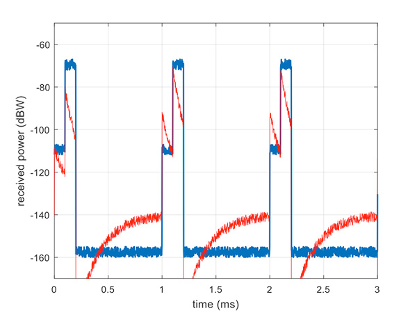
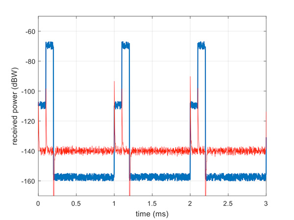
Figure 9 illustrates a slow AGC response, which is not particularly suitable. Compare this with Figure 10, where we have a fast AGC response, quickly adapting to the switches in power level. A receiver with this characteristic will be better able to track both pseudolite and satellite signals.
Figure 9. Pulsed pseudolites with slow AGC response (in red). (Figure: Michael Jones)Figure 10. Pulsed pseudolites with fast AGC response (in red). (Figure: Michael Jones)
Airborne Pseudolites
If you’ve read this far, you’ll now know that the main problems with ground-based pseudolites are lack of good geometry, signal blocking by terrain, and the horrendous near/far issues. Wouldn’t it be nice if we could raise the pseudolites to a really high altitude, and all these problems would go away? Wait, that’s the GPS satellite constellation!
Ok, let’s not put them that far up. But how about carrying pseudolites on high-altitude airborne platforms instead? Great idea, and that’s why this is a current thread of defense activity in various countries. High-altitude long-endurance (HALE) or HAPS (high-altitude pseudo-satellite; the clue is in the name) unmanned platforms can be used to carry pseudolites at high altitude.
This solution can provide excellent coverage, the pseudolites can be repositioned as necessary, and the near/far problem is also far less pronounced.
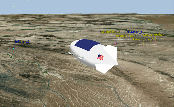
I leave you once again with our Afghanistan scenario, from the point of view of a high-altitude airship at 18,000 meters.
Figure 11. High-altitude platform, potentially carrying a pseudolite at 18,000 m. (Image: Michael Jones)
Dana Goward President, Resilient Navigation and Timing (RNT) Foundation
An apparent mass GPS spoofing attack in June involved more than 20 vessels in the Black Sea and suggests that Russia may be aggressively experimenting with signal disruption and spurious substitution.
“GPS equipment unable to obtain GPS signal intermittently since nearing coast of Novorossiysk, Russia. Now displays HDOP 0.8 accuracy within 100m, but given location is actually 25 nautical miles off…”
Subsequent dialog with the ship’s master and examination of various documents and screen grabs he furnished enabled navigation experts to conclude this was a fairly clear case of spoofing: sending false signals to cause a receiver to provide false information. Other vessels in the vicinity experienced the same problem.
The RNT Foundation has received numerous anecdotal reports of maritime problems with the automatic identification system (AIS), a tracking system used for collision avoidance on ships, and with GPS in Russian waters, though this is the first well-documented public account.
Russia has very advanced capabilities to disrupt GPS. More than 250,000 cell towers in Russia have been equipped with GPS jamming devices as a defense against attack by U.S. missiles. And there have been press reports of Russian GPS jamming in both Moscow and the Ukraine. In fact, Russia has boasted that its capabilities “make aircraft carriers useless.”
The U.S. director of National Intelligence issued a report on May 11 that states that Russia and other actors are focusing on improving their capability to jam U.S. satellite systems.
Assuming Russia is behind this, why would they do such a thing? Possibly to encourage use of GLONASS or their terrestrial loran system, Chayka, instead of GPS. Possibly for some security reason known only to them.
Whatever the reason, it reminds us of the vulnerability of GPS signals, and of the plethora of motives that “bad actors” — governmental or private criminal interests — may have to disrupt and deceive GNSS users.
And of the U.S. Coast Guard’s advice about GPS and all satnav: “Trust But Verify.”
Dana Goward is president of the Resilient Navigation and Timing Foundation. He is the proprietor at Maritime Governance LLC. In August 2013, he retired from the federal Senior Executive Service, having served as the maritime navigation authority for the United States. As director of Marine Transportation Systems for the U.S. Coast Guard, he led 12 different navigation-related business lines budgeted at more than $1.3 billion per year. He has represented the U.S. at IMO, IALA, the UN anti-piracy working group and other international forums. A licensed helicopter and fixed-wing pilot, he has also served as a navigator at sea and is a retired Coast Guard Captain.
Measure, a U.S. provider of drone solutions for enterprise customers, is expanding its drone engineering and equipment sales capabilities with the acquisition of Pilatus Unmanned.
Josh Kornoff, Pilatus Unmanned CEO and a pioneer in the commercial drone industry, will head Measure’s engineering team.
The acquisition marks the latest chapter in Measure’s rapid growth, highlighted by the recent introduction of new solutions and toolkits for the solar and broadcast news industries.
Pilatus Unmanned (previously known as Allied Drones) specialized in drone customization for commercial customers, leveraging Kornoff’s years of experience in designing and fabricating custom drone and payload solutions. Pilatus Unmanned was one of the first enterprise value-added resellers for commercial drone maker DJI.
“Measure is at the forefront of the emerging drone-as-a-service industry and is fundamentally changing the way businesses gather information critical to their operations,” said Kornoff, whose career also includes 15 years as a Hollywood special effects and pyrotechnics supervisor for nearly 1,000 commercials, music videos, television shows and films. “I’m excited to continue pushing the envelope in using drone technology to solve business challenges.”
Kornoff will lead Measure’s drone engineering team out of its new office in Huntington Beach, California, which includes an industrial facility equipped with the machinery, tooling, parts and components for drone customizations.
Kornoff will also serve as Measure’s lead technical advisor and will oversee support programs for toolkit customers.
“This acquisition will accelerate growth and allow us to continue to create groundbreaking solutions for our customers in energy, construction, telecommunications and media,” said Measure CEO and co-founder Brandon Torres Declet. “Expanding our engineering capacity and our ability to provide one-stop shopping for equipment and toolkits will help ensure that we can offer our customers solutions that are truly comprehensive.”
A team from Draper and the Massachusetts Institute of Technology (MIT) has developed advanced vision-aided navigation techniques for UAVs that do not rely on external infrastructure, such as GPS, detailed maps of the environment or motion capture systems.
When a firefighter, first responder or soldier operates a small, lightweight flight vehicle inside a building, in urban canyons, underground or under the forest canopy, the GPS-denied environment presents unique navigation challenges.
In many cases, loss of GPS signals can cause these vehicles to become inoperable and, in the worst case, unstable, potentially putting operators, bystanders and property in danger.
Attempts have been made to close this information gap and give UAVs alternative ways to navigate their environments without GPS. But those attempts have resulted in further information gaps, especially on UAVs whose speeds can outpace the capabilities of their onboard technologies.
For instance, scanning lidar routinely fails to achieve its location-matching with accuracy when the UAV is flying through environments that lack buildings, trees and other orienting structures.
Finding a Solution
DARPA awarded contracts to Draper and two other industry teams to create UAVs that autonomously sense and maneuver through unknown environments without external communications or GPS under the Fast Lightweight Autonomy (FLA) program. (Photo: Draper)
Working together under a contract with the Defense Advanced Research Projects Agency (DARPA), Draper and MIT created a UAV that can autonomously sense and maneuver through unknown environments without external communications or GPS under the Fast Lightweight Autonomy (FLA) program.
The team developed and implemented unique sensor and algorithm configurations, and has conducted time-trials and performance evaluations in indoor and outdoor venues.
“The biggest challenge with unmanned aerial vehicles is balancing power, flight time and capability due to the weight of the technology required to power the UAVs,” said Robert Truax, senior member of technical staff at Draper. “What makes the Draper and MIT team’s approach so valuable is finding the sweet spot of a small size, weight and power for an air vehicle with limited onboard computing power to perform a complex mission completely autonomously.”
Draper and MIT’s sensor- and camera-loaded UAV was tested in a number of environments ranging between cluttered warehouses and mixed open and tree filled outdoor environments with speeds up to 10 m/s in cluttered areas and 20 m/s in open areas.
The UAV’s missions were composed of many challenging elements, including tree dodging followed by building entry and exit and long traverses to find a building entry point, all while maintaining precise position estimates.
“A faster, more agile and autonomous UAV means that you’re able to quickly navigate a labyrinth of rooms, stairways and corridors or other obstacle-filled environments without a remote pilot,” said Ted Steiner, senior member of Draper’s technical staff. “Our sensing and algorithm configurations and unique monocular camera with IMU-centric navigation gives the vehicle agile maneuvering and improved reliability and safety — the capabilities most in demand by first responders, commercial users, military personnel and anyone designing and building UAVs.”
Draper’s contribution to the DARPA FLA program — documented in a recent research paper for the 2017 IEE Aerospace Conference — was a novel approach to state estimation (the vehicle’s position, orientation and velocity) called SAMWISE — Smoothing And Mapping With Inertial State Estimation.
SAMWISE is a fused vision and inertial navigation system that combines the advantages of both sensing approaches and accumulates error more slowly over time than either technique on its own, producing a full position, attitude and velocity state estimate throughout the vehicle trajectory.
The result is a navigation solution that enables a UAV to retain all six degrees of freedom and allows it to fly autonomously without the use of GPS or any communication with vehicle speeds of up to 45 miles per hour.
The team’s focus on the FLA program has been on UAVs, but advances made through the program could potentially be applied to ground, marine and underwater systems, which could be especially useful in GPS-degraded or denied environments.
New features are now available for TerraGo Magic, including laser-rangefinder integration, offset data capture, Apple and Google turn-by-turn navigation, and proximity alerts. Also new is extended waypoint guidance for finding off-road assets and infrastructure.
TerraGo Magic is a zero-code platform-as-a-service that enables customers to build their own custom mobile apps without writing any code by choosing from a menu of available, field-tested features.
TerraGo Magic is also the underlying platform used to build TerraGo Edge, which includes these latest features in version 4.1, available for download from the iTunes App Store and Google Play.
“With the addition of laser positioning and offsets for remote data collection, TerraGo helps us rapidly capture high-accuracy data for more assets and infrastructure, even those in difficult to reach locations,” said Fernando Mutia, IS supervisor for San Jose Water Company.
Partnership with Laser Technology
TerraGo is now partnering with Laser Technology Inc. (LTI) to enable all custom apps built by TerraGo Magic to seamlessly utilize LTI’s professional-grade laser rangefinders.
TerraGo Magic partners and customers can now add TruPulse rangefinder support to their custom iOS and Android apps with the click of a button using the TerraGo Magic zero-code app platform.
Also, Seiler Instrument – Geospatial, a partner of both LTI and TerraGo, will now add TruPulse support to its new Field2GIS app, which was built using TerraGo Magic and is now available from iTunes and Google Play.
“We’re very happy to launch this partnership that we feel responds directly to our customers’ goals and the industry’s demand for improving the quality and productivity of their field data collection work,” said Derrick Reish, senior product manager at LTI. “By leveraging laser precision and cloud-based mobility, we can help our joint customers collect the accurate data they need at a level of efficiency that wasn’t possible just a few years ago.”
“With TerraGo Magic, we totally change the traditional way of thinking about how custom mobile app versions get built, released and upgraded,” said Dave Basil, vice president of product development at TerraGo. “When we publish a new feature in Magic, it’s immediately available to all customer apps but doesn’t force it on all customers or require an upgrade beyond their control.”
“With TerraGo Magic’s platform-as-a-service, customers can evaluate and include features based on their priorities, timeline, business requirements and users’ needs, giving them the flexibility and control of a custom solution without the cost of custom app development,” Basil said.
Webinars
TerraGo is hosting a webinar on Aug. 15 at 12 p.m. ET with a live demonstration of the latest features in TerraGo Magic Apps and TerraGo Edge.
To learn more about the technical details and operational benefits, join TerraGo and LTI in the webinarAdvanced Mobile Data Collection Finds the Range with Laser-Precision, on Aug. 22 at 12 p.m. ET.
Preliminary construction is underway on a new, $350 million Lockheed Martin facility that will produce next-generation satellites.
The new facility, located on the company’s Waterton Canyon campus near Denver, is the latest step in an ongoing transformation, infused with innovation to provide future missions at reduced cost and cycle time, the company said.
The new Gateway Center, slated for completion in 2020, includes a state-of-the-art high bay clean room capable of simultaneously building a spectrum of satellites from micro to macro.
Spacecraft now in production at the site include the Air Force’s GPS III satellites (in the GPS III Processing Facility), NASA’s InSight Mars lander, NOAA’s GOES-R Series weather satellites and commercial communications satellites.
The facility’s paperless, digitally-enabled production environment incorporates rapidly-reconfigurable production lines and advanced test capability.
It includes an expansive thermal vacuum chamber to simulate the harsh environment of space, an anechoic chamber for highly perceptive testing of sensors and communications systems and an advanced test operations and analysis center.
The Gateway Center will be certified to security standards required to support vital national security missions.
“This is our factory of the future: agile, efficient and packed with innovations,” said Rick Ambrose, executive vice president of Lockheed Martin Space Systems. “We’ll be able to build satellites that communicate with front-line troops, explore other planets and support unique missions.”
“You could fit the Space Shuttle in the high bay with room to spare,”Ambrose said. “That kind of size and versatility means we’ll be able to maximize economies of scale, and with all of our test chambers under one roof, we can streamline and speed production.”
Lockheed Martin expects the construction effort to employ a total of 1,500 contractors during the three-year construction phase. Lockheed Martin has added more than 750 jobs to its Colorado workforce since 2014, and has about 350 job openings in the Denver area alone.
Lockheed Martin’s planned satellite integration facility, the Gateway Center, is slated for completion in 2020. (Photo: Lockheed Martin.}
The building will accommodate that recent growth and new future projects. State and local officials in Colorado have helped strengthen the aerospace industry and foster an environment that helps aerospace companies thrive and grow.
“Aerospace is an engine of innovation and growth for America, and we’re investing in infrastructure and technology to help strengthen the nation’s leadership in military and commercial space and scientific exploration,” added Ambrose. “We’re transforming every aspect of our operations to help our customers stay ahead of a rapidly-changing landscape. The Gateway Center, coupled with advancements in 3D printing, virtual reality design and smart payloads, will deliver game-changing innovations while saving our customers time and money.”
Lockheed Martin’s Waterton Canyon campus has been a hub of space innovation since the 1950s, with more than 4,000 employees and a wide range of industry-leading design, manufacturing and test facilities on site.
Companies selected by Lockheed Martin for the project include Hensel Phelps as the general contractor, Matrix PDM Engineering and Dynavac for thermal vacuum chamber design and construction, and ETS-Lindgren for anechoic chamber design and construction.
GeoCue Group has released a GNSS positioning system that will allow users of DJI Phantom 4 Pros and Inspire 2 drones, as well as most drones using higher end cameras, to achieve survey-level accuracy with minimum ground control.
Loki, GeoCue’s new direct geopositioning system for small unmanned aerial systems, solves the two fundamental problems associated with this technology:
Positioning Accuracy. Loki uses the new AsteRx-m2 multi-frequency, multi-constellation GNSS engine from Septentrio, which has 448 hardware channels.
Camera Events. GeoCue has invented a patent-pending method of detecting camera events from Phantoms/Inspires and synchronizing those events to GNSS positioning. No modifications to the drone are necessary; the adapter cable is “plug and play.”
GeoCue’s Loki positioning kit uses the Septentrio AsteRx-m2 GNSS engine.
Loki is a self-contained kit that provides all of the hardware and software needed to equip a drone with a post-processed kinematic (PPK) multifrequency, multi-constellation, differential, carrier-phase GNSS.
Using a local base station (not included), Loki provides centimeter-level positioning with minimal, and in some cases, no ground-control points (though GCPs are always recommended for quality assurance).
“GeoCue has been a long-time Septentrio OEM development partner,” said Neil Vancans, vice president of Septentrio Americas. “They have offered our previous generation sUAS board on their high-end AV-900, achieving remarkable results in both accuracy and reliability. By solving the problem of connecting the virtual camera trigger on DJI drones to our AsteRx-m2 GNSS engine, they can achieve professional mapping accuracies with consumer-grade UAVs.”
DroneDeploy of San Francisco has become a leader in cloud-based processing for DJI, as well as other drones. DroneDeploy has enabled users of Phantom and Inspire drones to easily upload drone images, work online with analytics, and download point clouds and orthophotos to desktops for advanced processing.
Without Loki, achieving acceptable network accuracy requires the time-consuming placement of ground-control targets throughout the mapping site.
GeoCue and DroneDeploy have been working together to ensure a smooth Loki-DroneDeploy workflow from field to finish.
“The GeoCue Loki system is an exciting product for anyone using drones to make maps with high accuracy,” said Mike Winn, CEO and co-founder of DroneDeploy. “The Loki’s combination of high-end GNSS positioning and DJI camera synchronization enables survey-grade accuracy with the simplest workflow that we’ve seen — making the Loki a great fit for the DroneDeploy platform.”
“I am very excited to be working with industry leaders such as DroneDeploy on our Loki project,” said Lewis Graham, president and CTO of GeoCue Group. “Loki provides high accuracy positional data to downstream processing solutions. More significantly, it does this for DJI Phantom 4 Pro and Inspire 2 drones. Combining DJI, Loki and cloud processing solutions such as DroneDeploy provides a very streamlined and cost effective solution for high accuracy site surveys.”
The Loki kit includes:
Loki PPK Controller using the Septentrio AsteRx-m2 GNSS engine (GPS L1, L2, L5 and GLONASS L1, L2, L3, 448 hardware channels).
Maxtena M1227HCT-A2-SMA high performance, active, multiband GNSS antenna
Antenna ground plane with mounting kit
Antenna to controller cable
USB cable for data transfer and Loki controller charging
Personality cable (user selects either DJI or DSLR)
AirGon ASP software suite
Mounting kits for DJI Inspire 2 and Phantom 4 Pro
1 year of maintenance and technical support
Loki requires a local multifrequency base station (not included but available from GeoCue). Loki is shipping to early adopter customers in August 2017. It will be available for the general market in September 2017.
It will release with direct support for DroneDeploy and AirGon’s Bring Your Own Drone (BYOD) Mapping Kit. Loki’s introductory price will be USD $4,995. GeoCue is currently accepting preorders.
Loki will be on display September 6-8 at the InterDrone 2017 conference in Las Vegas and at Commercial UAV Expo, also in Las Vegas, October 24-26. A workshop dedicated to high accuracy mapping with DJI drones using Loki is being held in conjunction with the Commercial UAV Expo. Register at www.expouav.com.