General Dynamics Mission Systems has introduced its HOOK3 combat survival radio.
The HOOK3 radio is 30 percent smaller and 40 percent lighter than the HOOK2 radio, and has a smaller, longer lasting battery, the company said.
In addition, the embedded GPS module has 32 channels enabling a faster position acquisition time, more accurate position reporting and better performance under forested or densely vegetated areas or near structures.
The radio transmits encrypted GPS, user identification, situation reports and other critical information to rescue teams and aircraft in short bursts to reduce the risk of detection. The radio can also use multiple GNSS.
The new radio provides direct line-of-sight voice and encrypted two-way data communications to help combat search and rescue teams quickly and accurately locate and rescue downed pilots and isolated military personnel, the company added.
The HOOK3 was designed using feedback from military personnel who rely on a survival radio in emergency situations. The new radio automatically activates and securely transmits location data when specific G-Force or the presence of salt water is detected by the radio.
“General Dynamics has delivered more than 36,000 combat search and rescue radios to 36 countries over the past 30 years,” said Paul Parent, a vice president of General Dynamics Mission Systems. “These radios have helped save the lives of military personnel isolated or in harm’s way during a mission.”
“The HOOK3 provides military personnel in emergency situations a highly reliable, easy-to-use, secure radio critical to their successful recovery.”
The General Dynamics HOOK3 radio is interoperable with all HOOK2 family radios, Quickdraw2 and SATCOM base stations currently used by U.S. and international military personnel.
The HOOK3 is designed for coalition operations, and the user-friendly transceiver is software-defined, enabling new features, waveforms and software upgrades to be added as they become available.
A: Integration with GNSS and other sensors in most every military vehicle or weapon-control system will enable inertial sensor developers to focus on driving improvements in performance for the two fundamental parameters that a sensor-fusion INS filter cannot estimate: noise and in-run bias stability. Ultra-tightly coupled sensor fusion of GNSS with range-, speed- and video position-sensing, with tactical and navigation grade inertial sensors optimized for noise and in-run, will enable design of robust GPS chip-level solutions for high-dynamic, high-performance navigation for nearly any military environment or engagement.
Michael Whitehead, chief technology officer, Hemisphere GNSS
A: Previously used for military applications, inertial technology has become mainstream as performance-to-cost has improved with the emergence of low-cost microelectromechanical systems (MEMS). Precise point positioning (PPP) advancements have driven GNSS accuracies to 4 cm or better, but long PPP initialization times are problematic in challenging environments where reconvergence is often required. Tightly coupled integration of PPP and navigation-quality MEMS will overcome limitations of both technologies, yielding high accuracy with high availability, even in challenging environments.
Chris Wheeler, manager, telematics and connected sites, Trimble Navigation
A: The availability of multi-frequency GNSS receivers with inertial components on a small lightweight board can now deliver centimeter-accurate INS/GNSS solutions, so that OEMs and integrators can significantly improve reliability and robustness in harsh or GNSS-denied applications or for solutions such as UAVs. The advances provided by MEMS inertial components increase overall efficiency by reducing the number of ground control points while still meeting the needs for a low weight and power consumption solution.
A major new global-scale venture by China’s Internet giant Baidu aims to put artificial intelligence behind the wheel of fully autonomous vehicles on the road by 2020.
Regulatory considerations aside, the technical challenges are considerable, but like its U.S. counterpart Google, Baidu is pushing a big pile of chips onto its artificial intelligence (AI) bet.
Similar to Android, it has made much of the Apollo program’s code, which is completely open-source and available on Github.
The ecosystem, launched at the Baidu developers conference in Beijing in April, has enlisted at least 50 partners worldwide, with more anticipated.
A key participant is AutonomouStuff, which started out as an autonomous components supplier, but lately self-transformed into a full-fledged system integrator, with core GNSS and inertial capabilities drawn from manufacturers in the positioning, navigation and timing (PNT) industry.
Other Apollo partners include major Chinese auto manufacturers; tier 1 suppliers such as Bosch, Continental Automotive and ZF Friedrichshafen AG; components providers such as NVIDIA and Microsoft Cloud; mapper TomTom; and drive-sharing companies.
AutonomouStuff kitted out two standard Lincoln MKZ sedans for demonstration drives at the Beijing conference, with one technician completing each vehicle in about three hours — a task that would normally take a team of workers up to six weeks. The two Lincolns then drove simultaneously, driverless, around a test track.
The technology has been developed to be transferrable to other vehicles. Models already demonstrated include the Ford Fusion, a street-legal golf-cart-type electric vehicle called the Polaris GEM, and an off-road Ranger buggy platform.
AutonomousStuff presents the Apollo kit at the Baidu developer’s conference in April. (Photo: AutonomousStuff)
How It Works
Each car is modified by adding lasers, camera, radar sensors, GPS and inertial measurement unit (IMU), a drive-by-wire computer interface and computer engine.
Laser Sensors. A 64-beam lidar sensor on the roof gives a 360-degree field of vision for mapping, and lidar localization algorithms drawing on more than 2.2 million points of data per second generate a point cloud giving distance, angle and intensity values. This data is integrated with data from the GPS and IMU to generate a base map. Two smaller lidar sensors on the front corners of the vehicle provide obstacle detection and tracking.
Rotating four-beam laser sensors with 110-degree view and 200-meter range cover blind spots and facilitate fusing all raw data into one scan. Together, they detect other cars, trucks, bikes, pedestrians and background objects, and generate detailed data on their position, motion and shape. Distance and angular resolution data are used to offset camera and radar data.
Cameras. The platform uses two visible-light cameras mounted on the windshield, relying on laser sensors for nighttime operation. An image-processing chip provides real-time detection of lanes, vehicles and pedestrians, and measures dynamic distances from the vehicle.
Radar. Five radar sensors provide object detection, with various placements around the vehicle, and varying ranges and fields of view. Jointly, they provide a 360-degree bubble around the car.
Navigation. The kits provide GPS navigation combined with a tightly coupled IMU to provide data when GPS is not available.
Together, this provides accuracy to 2 cm, according to the company, when used with a real-time kinematic (RTK) base station; this obviously limits vehicle range. Another option is to use correction data from satellite-based correction services such as TerraStar, yielding achievable accuracies on the order of 4 cm.
Documentation
The aim of the Apollo project is to enable partners and customers to develop their own self-driving systems. The information supplied by Baidu encompasses a complete set of end-to-end instructions to convert a regular car to an autonomous-driving vehicle:
Software Instructions. A set of files that contain:
architecture of the classes and the files within each class.
code instructions for:
coordinate system
third-party libraries
calibration table.
Hardware Documents. Instructions to install the hardware and software for the vehicle include:
Vehicle:
industrial PC (IPC)
GPS
inertial measurement unit (IMU)
controller area network (CAN) card
hard drive
GPS antenna
GPS receiver
Software:
Ubuntu Linux
Apollo Linux kernel
Hardware reference guides:
vehicle
IPC
GPS
CAN card
https://youtu.be/eiSfP-Rn6n4
Manufacturers
The AutonomouStuff Apollo kit incorporates a choice, depending on user needs, of a selection of NovAtel GNSS receivers, including the ProPak6 GNSS receiver and the SPAN-IGM-A1 GNSS+IMU combined system, IMUs such as the IMU-ISA-100C incorporating Northrop-Grumman Litef GMBH’s inertial measurement technology, and antennas such as the GNSS-703-GGG-HV high vibration triple-frequency GPS, GLONASS, BeiDou, and Galileo antenna.
A 64-beam Velodyne lidar sensor and 16-beam HDL-16E provide laser data.
The onboard computer system is the AStuff Nebula embedded controller, an IPC powered by an Intel Skylake core i7-6700 CPU. The CAN card used for the IPC is the ESD CAN-PCIe/402.
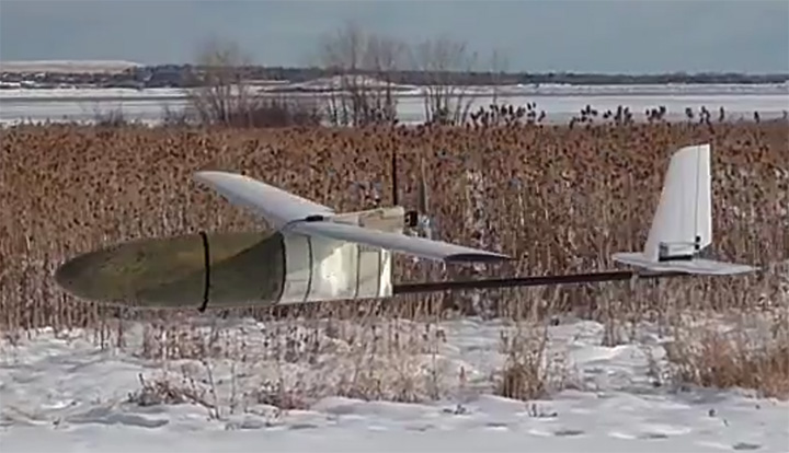
Drones have become a serious threat, able to penetrate airspace for surveillance or with an explosive payload.
The Islamic State has used weaponized drones against both Syrian and Iraqi forces; groups like Hezbollah and Hamas have sent drones into Israel and are said to be working on upgrading their UAVs for use in both intelligence gathering and offensive operations.
On April 27, Israel used a Patriot missile to take down a drone entering Israeli Airspace from Syria. At $3 million per missile, the Patriot system is an expensive way to down a device that may only be worth $200. Israel has also intercepted drones with fighter jets.
Systems developed by two Israeli companies provide less expensive — and quickly reactive — solutions.
The Drone Dome system uses Laser, RF and Radar. (Photo: Rafael)
Drone Dome.Rafael Advanced Defense Systems Ltd. has developed a radar and laser-beam system for detecting and destroying drones, with the company adapting its existing laser systems to handle the threat.
Once the system’s radar identifies targets, its laser system destroys them.
Drone Dome also features a jamming system for disrupting communications between the drone and its operator. Drone Dome’s range reaches several miles, but causes minimal interruptions to other systems in nearby urban areas.
The standard Drone Dome system comprises a RADA RPS-42 S-band multi-mission hemispheric radar, a Controp MEOS electro-optical (EO)/infrared surveillance suite, a communications package, and the C-Guard RD jamming and NetSense Wideband detection sensor systems developed by Netline. The UAV threat is neutralized by activation of directional GPS/GNSS and radio-frequency inhibitor/jammer devices.
The RPS-42 is a four-panel tactical air surveillance system delivering 360-degree coverage in azimuth and 90 degrees in elevation, with a detection range of 30 kilometers — including the detection of a minimum target size of 0.002 meters square at a range of 3.2 kilometers — at altitudes from 30 to 30,000 feet. The RPS-42 is designed to detect, track and classify all classes of UAV.
DROM Defense.ORAD’s DROM Drone Defense System can detect an approaching drone at more than 3.5 kilometers away and take command, neutralizing it and landing it far from the operator.
With a weight of 38 kilograms, ORAD’s DROM system comes pre-engineered and pre-assembled. It is mobile and easily deployed on land or at sea in any weather conditions and has an effective coverage range of 3.5 kilometers. It has a 2-kilometer neutralization capability.
Once intercepted, the system can land a hostile a UAV in a pre-defined location, keeping any intelligence it gathered out of enemy hands. It can also identify the location of the operator.
The system’s RF detection unit analyzes signal channels and radio transmissions to spot drones. Once detected, an alarm alerts the system operator.
ORAD has sold the system to clients in several countries including Portugal, Spain and Thailand. The company is in talks with Israeli agencies interested in purchasing the system.
The Apex tracker has Taoglas inside. (Photo: STATSports)
When the world’s best athletes take the field, many are equipped with a GPS-based performance monitor that tracks a wealth of data. By monitoring in real time the players’ actions, professional sports teams can collect and analyze data that gives them an edge over the competition.
STATSports is a provider of GPS player tracking and analysis solutions for some of the biggest sports franchises in the world. Teams in the English Premier League, La Liga, National Football League, National Basketball Association and other leagues rely on STATSports to help them improve performance and strategy, and reduce injuries.
Tracking Key Metrics. STATSports’ Apex System includes the Apex Pod and Apex Software. The Apex Pod is an ergonomically designed unit that curves to fit players’ backs. The pod is inserted into a specially designed vest or base layer.
It tracks a variety of metrics, including a player’s total distance, speed, accelerations, decelerations, heart rate, fatigue level and other variables that teams can use in real time or alongside post-game reviews. The data is processed through Apex Software, which creates reports and visual tracking mechanisms to compare players, track players over time and provide metrics personalized for each team.
A tablet app gives coaches portable functionality. (Photo: STATSports)
Apex Live Streaming uses multiple channels and synchronized mesh networking to deliver data streams from players to Apex Software for analysis. Apex delivers GPS speed and positional data; heart-rate variability; and digital compass, gyroscopic and accelerometer data. It transmits half a million numbers every minute during training and games for a squad of more than 30 players.
Accurate Antenna
In devices so small and sensitive, antennas can be the most common point of failure in the communications chain, said Dermot O’Shea, co-CEO of Taoglas. STATSports evaluated several antenna options before selecting Taoglas.
Taoglas’ 25×25-mm AGGBP.25B is a two-stage 28-dB active GPS patch antenna module that provides positional accuracy in a small form factor.
With a few dozen players and coaches on the field in training and at games, highly accurate positioning is critical. Players move quickly and are often clustered around a ball, making it difficult to accurately track player movement. STATSports required location accuracy within 1 meter, precision that
Taoglas delivered.
The LA Galaxy team uses STATSports. (Photo: LA Galaxy)
Because the STATSports technology captures data in real time, teams can make real-time tactical and strategic decisions and adjustments instead of waiting for post-game analysis.
However, with that many antennas and transmissions in close proximity, interference can be an issue. Taoglas’ solution includes a front-end surface acoustic wave (SAW) filter in front of the two-stage low noise amplifier (LNA) to reduce out-of-band noise, such as signals from nearby cellular transceivers.
The real-time nature of STATSports’ solution means the company also requires a condensed time to first fix — when the devices are turned on, STATSports needs them to register a signal quickly and begin to receive data. The Taoglas antenna is ready within 30 seconds of powering on.
STATSports’ proximity to Taoglas’ Wexford, Ireland, headquarters and development labs means the teams can collaborate on new functionality as STATSports develops increasingly advanced performance-tracking solutions.
The ALT1250 narrowband CAT-M1 and NB1 (NB-IoT) chipset includes GNSS functionality. Its extreme level of integration eliminates the need for most external components required to design a cellular Internet of Things (IoT) module. Less than 100 x 100 square millimeters, the ALT1250 module features support for both Release 13 standards — CAT-M1 and NB1. It includes a wideband RF front end supporting unlimited combinations of LTE bands within a single hardware design; a multi-layered and hardware-based security framework; an internal application MCU subsystem; and packaging that enables standard, low-cost printed circuit board (PCB) manufacturing.
Carrier-grade, packet-based timing and synchronization
Hardware on the TimeProvider 5000 IEEE 1588 Precision Time Protocol (PTP) grandmaster clock has been updated to support Internet Protocol version 6 (IPv6) and multi-GNSS constellations to ensure better reception and higher security in a wide variety of telecommunications network applications. Looking forward to mobile infrastructure with LTE-Advanced (LTE-A) and 5G services, support for IPv6 and alternate GNSS constellations is rising in importance for deploying a robust, secure and future-proof synchronization network. The device offers multiple constellations in accordance with the directives in certain countries to remove sole dependency on GPS. Support for GLONASS and Galileo also makes systems more robust and secure to certain GNSS vulnerabilities. The TimeProvider 5000 provides redundant hardware, user-configurable PTP profiles and Synchronous Ethernet (SyncE) support with optical small form-factor pluggable (SFP) modules.
Designed for effective data collection, management
The Precis-BX316R is a GNSS Post-Processing Kinematic (PPK) board for accurate positioning. It supports raw measurement output from two antennas: GPS L1/L2, GLONASS G1/G2 and BeiDou B1/B2 from the primary antenna and GPS L1/L2 from the second antenna. The SD card on board (up to 32 GB) makes it convenient for users to collect data for post processing. Working with GNSS antennas, it can output stable measurement in challenging conditions. Integrated with versatile interfaces and connectors, Precis-BX316R aims to facilitate applications such as precision navigation, precision agriculture, surveying and UAV, and enforcing effective GNSS data management.
The u-blox SAM-M8Q GNSS receiver with integrated antenna is housed in a 15.5 x 15.5 x 6.3 millimeter package. It can be embedded in small devices that require location information, such as asset tracking and telematics systems, and generic automotive after-market applications. The module offers simultaneous reception of GPS, GLONASS and Galileo. The combination of an integrated wide-band antenna along with the module’s SAW filter and low-noise amplifier (LNA) architecture ensures that the SAM-M8Q receiver delivers robust performance in the presence of high-frequency signals from other electronic equipment that can cause interference, such as cellular modems.
Tight pre-filter protects against high-level cell signals
The TW3892 is a through-hole mount dual-band plus L-band GNSS antenna. It employs Tallysman’s Accutenna technology and is capable of receiving GPS L1/L2, GLONASS G1/G2, BeiDou B1, Galileo E1 plus L-band correction services (1213MHz to 1261MHz + 1525MHz to 1610MHz). The TW3892 is a precisely tuned antenna with a tight pre-filter to protect against intermodulation and saturation caused by high-level cellular 700 MHz and other signals.
The credit-card sized AsteRx-m2 offers all-in-view multi-frequency, multi-constellation tracking and centimeter-level real-time kinematic (RTK) position accuracy for low power. It can receive TerraStar satellite-based correction signals for precise point positioning (PPP). The board features Septentrio’s AIM+ interference mitigation system that can suppress a wide variety of interferers, from simple continuous narrowband signals to complex wideband and pulsed jammers. The RF spectrum can be viewed in real time in both time and frequency domains.
Spirent’s TTsuite-WAVE-DSRC (Wireless Access in Vehicular Environments – Dedicated Short-Range Communications) conformance test solution includes a set of tests required for U.S. Department of Transportation (USDOT) certification. TTsuite-WAVE-DSRC consists of four different protocol conformance test suites as per the USDOT Certification Operating Council (COC) conformance test specifications. It enables full test automation, includes frameworks for individual adaptation, and it is extensible with many plug-ins to meet constantly changing development requirements. TTsuite-WAVE-DSRC is targeted at companies supplying or testing WAVE-DSRC ITS technology.
The SP90m GNSS receiver is a powerful, highly versatile, ultra-rugged and reliable GNSS positioning solution for a wide variety of real-time and post-processing applications. Integrated communications options include Bluetooth, Wi-Fi, UHF radio and cellular modem as well as two MSS L-band channels to receive Trimble RTX correction services. The SP90m can be used as a base station, campaign receiver, continuously operating reference station (CORS), real-time kinematic (RTK) or Trimble RTX rover, or be integrated on-board a machine. The receiver uses all available GNSS signals to deliver fast and reliable positions in real time, and allows the connection of two GNSS antennas for precise heading or relative positioning determination without a secondary GNSS receiver. It features an internal removable battery, internal memory and optional accessory kits for specific applications.
For total stations, robotics and GNSS rover systems
GeoPro Field provides a graphical user interface designed to collect field measurements for land surveying and construction activities. GeoPro Field is a tool to collect and import measurement data into design and drafting software, increasing productivity with CAD functionality in the field. It is compatible with various software workflows, and point files are easily exported to third-party software. Sokkia GeoPro Office is the office-processing complement to the field software — designed to clean, process, and analyze field data into its easiest-to-use form. The office software can also be expanded with an optional 3D and road design module, for further versatility to design roads with the processed field measurements.
Hemisphere GNSS’ C321 GNSS Smart Antenna is designed for heavy highway and site construction. When paired with SiteMetrix Site Management software, the multi-frequency, multi-GNSS C321 antenna can be used as an all-in-one construction base and rover site controller. The C321 combines the Athena GNSS engine and Atlas L-band correction technologies. The ruggedized antenna is designed for the most challenging environments and meets IP67-standard requirements. Powered by Athena GNSS engine, the C321 provides best-in-class, centimeter-level RTK. Athena excels in virtually every environment where high-accuracy GNSS receivers can be used. Tested and proven, Athena performs with long baselines in open-sky environments, under heavy canopy, and in geographic locations experiencing significant scintillation. The C321 ships pre-configured to test-drive corrections from Hemisphere’s Atlas L-band corrections service. C321 also uses Hemisphere’s aRTK technology, powered by Atlas. This feature allows the receiver to operate with RTK accuracies when RTK corrections fail. If the C321 is Atlas-subscribed, it will continue to operate at the subscribed service level until RTK is restored.
Toughpad is Panasonic’s newest professional-grade notebook, specifically designed for precision agriculture, machine control and robotic guidance applications in harsh environments and conditions. Embedded in the tablet is a u-blox NEO-M8 GNSS receiver module delivering high integrity and precision in demanding applications worldwide. First tested for collecting snow in Hokkaido, Japan, the Toughpad tablet uses Panasonic’s own satellite positioning technology combining a satellite radio receiver module, wireless WAN, and a single-band real-time kinematic (RTK) GNSS receiver connected to an external antenna. The system enables high-precision positioning down to centimeter level in open-sky conditions.
Esri has released an Ecological Marine Units (EMU) app for mobile devices. The app provides a new way to measure marine environments on a 3D interactive map for more cost-effective fishery planning and informed conservation. It is a resource for scientists, educators, governments and industries seeking accessible information and imagery about the ocean’s long-term physical and nutrient properties. The EMU app puts data such as temperature, salinity and dissolved oxygen from 52 million locations throughout the world’s oceans at any user’s fingertips. This data informs how livable marine environments are for ocean-dwelling species as well as the overall health of the ecosystem. The app is free from the App Store and Google Play.
Delivers CAD drawings from ground-penetrating radar data
DX Office Vision is a utility post-processing software for mapping ground-penetrating radar (GPR) data from the field into a CAD drawing. It allows even non-experienced users to obtain professional 3D CAD drawings and visualize the detected underground utilities in a simple way. The intuitive interface enables users to filter, select, identify and make annotations of the located targets. With DX Office Vision, post-processing for all ground-penetrating data requires no add-on or third-party software.
Averna has entered a strategic partnership with M3 Systems to distribute their StellaNGC GNSS Simulator on VST NI platforms for the infotainment segment of the automotive market. M3 Systems’ GNSS simulator, based on National Instruments’ Vector Signal Transceiver (NI VST), will now be available as part of Averna’s AST-1000 platform, extending its capability to navigation and GNSS testing. Launched in July 2016, the AST-1000 is an RF solution designed for radio, navigation, video and connectivity testing. Also based on the NI VST, the software-defined AST-1000 supports infotainment RF signals, including AM/FM, DAB, RDS, HD Radio and Sirius/XM as well as GNSS navigation. The combination provides a comprehensive solution and enables applications for testing infotainment systems.
The LE940A9 automotive-grade module is designed to support LTE Advanced Category 9 (Cat 9) networks. The series offers three multi-band, multi-mode variants — including voice-over-LTE (VoLTE) — and is optimized for automobile manufacturers to deploy next-generation connected-car technology in world markets. The LE940A9 delivers 450 Mbps download and 50 Mbps upload speeds with extremely low latency and advanced security. The xE940A9 40×40 mm LGA form factor nests with the 34x40mm Telit xE920 automotive module family, offering flexibility for the OEM or tier-one integrator. It powers the entire connected-car platform, supporting current needs while including advanced features that enable future integration of upcoming services. The module can run in-vehicle applications inside a secure processing environment from the built-in application processor, storage and memory. Automotive application programs can run entirely and securely on the module itself, protected by advanced cyber-security capabilities.
Nine antennas including four LTE, two Wi-Fi, GNSS, SDARS and DSRC
The Axiom is a reference design for a low-profile, compact multiple-antenna solution for the next generation of connected cars. The Axiom reference design helps automobile manufacturers more quickly advance antenna configurations that work for their particular make and model. As many as 18 antennas are needed to power the next-generation connected car, including multiple cellular antennas for network connectivity; Wi-Fi for hotspot connectivity; GNSS for navigation, emergency call systems and other location-based technologies; satellite radio (SDARS); AM/FM antennas; radar antennas for object detection; Bluetooth antennas for smartphones and other devices, and dedicated short-range communications (DSRC) antennas for vehicle-to-vehicle/infrastructure applications.
Ruggedized module based on military design principles
The Duro is a ruggedized version of Swift Navigation’s Piksi Multi dual-frequency RTK GNSS receiver. Built for outdoor operations, Duro combines a rugged enclosure with centimeter-accurate positioning. Leveraging design principles typically used in military hardware, the GNSS sensor is protected against weather, moisture, vibration, dust, water immersion and unexpected circumstances that can occur in outdoor long-term deployments. It is ready to connect out of the box. Primary industries for this product include robotics, precision agriculture, mapping, military, outdoor industrial and maritime.
The μINS is a precision miniature GPS-aided inertial navigation system (GPS-INS) designed to provide high-quality direction, position and velocity data for drones and robotic applications. It uses a u-blox L1 GPS receiver. Advanced algorithms fuse output from micro-electro-mechanical system (MEMS) inertial sensors, magnetometers, barometric pressure, and a high-sensitivity GPS (GNSS) receiver to deliver fast, accurate and reliable attitude, velocity and position even in the most dynamic environments. Sensor calibration, standard on all units, minimizes undesirable effects of manufactured variation and maximizes sensor performance. Features include GPS UTC time synchronization; an inertial measurement unit with comprehensive calibration for bias, scale factor and cross-axis alignment; –40°C to 85°C temperature compensation; a measurement of 15.6 x 12.5 x 6.3 millimeters; and a weight of 2 grams.
The Scout B-330 UAV helicopter is built with a payload capacity of up to 50 kg. (110 pounds), flight endurance of at least three hours, and the capability of flying at high altitudes (up to 3,000 meters above sea level) in a typical mission scenario. This includes a full autonomous take-off sequence, a mission flight at variable speed, and a landing sequence. The Scout B-330 is specifically designed for lidar-based powerline mapping missions. It pairs with Riegl airborne and unmanned lidar sensors such as the Riegl VP-1 Helicopter Pod, the Riegl VUX-1UAV lightweight UAV laser scanner, and the Riegl VUX-1LR lightweight, long-range airborne laser scanner.
Certifiable application for unmanned traffic management
The IRIS UAS Airspace Situational Awareness application meets the requirements of the DO-278A Assurance standard for Air Traffic Management systems, providing a certifiable option to monitor drones and airspace. By anticipating the regulatory requirements for airspace visualization with Unmanned Traffic Management or UTM, the IRIS display will be a regulatory-approved component increasing the safety of commercial drone flight operations — especially when operating beyond visual line of sight (BVLOS). The application had its genesis in supporting military UAV flight operations and was developed to help operators safely pilot UAVs in BVLOS operations. It was also used by regional airspace UTM managers to monitor the operations of multiple drones simultaneously. The DO-278A standard is used by certification authorities such as FAA, EASA and Transport Canada.
The miniature Epsilon series of gyro-stabilized gimbals now have a precision geo-pointing feature. The feature, Precision Geo-Lock, combines a GPS-aided inertial navigation system (GPS/INS) with dedicated software algorithms and payload operator software. Precision Geo-Lock provides the user with highly accurate target geo-location, range-to-target, as well as Geo-Lock functionality and moving map user interface. It incorporates VectorNav’s VN-200, which offers a high-level of performance in a form factor small enough to be integrated directly into the optical bench of the gimbal. Precision Geo-Lock provides better than 0.3-degree accuracy and is plug-and-play, so the customer can install the Epsilon gimbal and get accurate results on any platform and in a high-vibration environment.
StepInside and partner Flowscape to help Sweden HQ team easily find available workspace and colleagues
The Senion StepInside indoor positioning system has been deployed in the 500,000-square-foot Kista (Stockholm) headquarters of telecom company Ericsson.
Using personal or work-issued smartphones, more than 4,000 employees working throughout 20 floors distributed over four buildings can now use a corporate app to easily find available rooms and spaces to work, the company said.
The indoor positioning system is designed by Senion’s longtime partner Flowscape. With StepInside integrated into the Flowscape platform, the two companies will help Ericsson employees reduce wasted time searching for people, places or things, increasing productivity.
The StepInside software development kit (SDK) offers location readings in latitude, longitude and floor level in real time. The SDK can easily be integrated into any smartphone application. StepInside relies on an advanced sensor fusion algorithm that works with the smartphone’s movement and radio sensors to provide accurate and robust positioning.
“Indoor positioning technology is perfect for large offices with multiple floors, offices, and meeting spaces — the bigger and more intricate the better,” said Christian Lundquist, CEO and co-founder of Senion. “We’re seeing that large companies are taking serious measures to combat friction in order to increase both productivity and employee satisfaction. We now aid Ericsson in giving back time to their employees so they can be more efficient in their day-to-day work.”
The implementation of StepInside at Ericsson is part of the company’s larger global platform designed to enable rapid IoT application development.
“We looked carefully at the benefits of using IPS [indoor positioning system] in our offices, and determined the system would pay for itself in productivity savings alone,” said Magnus Arlidsson, global head application platform for IoT at Ericsson. “Our initial roll-out focuses on productivity improvements by saving employees time they might waste searching for things, such as conference rooms or places to work.”
The system as implemented today is the starting point for a bigger roll-out with additional workplace enhancements at Ericsson.
Senion’s comprehensive IPS services include analytics, wayfinding, geofencing, friend finder and tracking. With more than 300 indoor positioning system installations globally, Senion has worked closely with shopping malls, hospitals, corporate campuses and more to improve workflows. Senion is headquartered in Linkoping, Sweden, and San Francisco.
Aircraft to Provide Wildfire Measurements in Support of NOAA Fire Weather Forecasting
The U.S. National Oceanic and Atmospheric Administration (NOAA) has selected a small unmanned aircraft system (sUAS) for wildfire measurements and observations in support of its FIREX field mission and the fire weather forecasting initiative.
Black Swift Technologies will deliver to NOAA a tightly integrated system consisting of an airframe, avionics and multiple sensors capable of research-quality measurements of CO2, CO, aerosol, RH, p and T in wildfire plumes, as well as multispectral high-resolution maps of wildfires.
The SuperSwift sUAS will be operated by the University of Colorado’s Integrated Remote & In Situ Sensing Program (IRISS) in close collaboration with NOAA.
“One of the purposes of IRISS is to work with the science community to develop and deploy platforms which make primarily in situ measurements,” said Brian Argrow, IRISS director. “This naturally lead us to partnerships with NOAA on the science perspective, and to Black Swift Technologies for their sUAS technology and expertise. It’s a partnership that looks like a three-legged stool with the science interest of NOAA, the technology and engineering expertise of IRISS, and the unique sUAS platform designed by Black Swift Technologies, as the corresponding legs.”
The FireFOX sUAS is based on Black Swift’s commercially available SuperSwift airframe and SwiftCore Flight Management System — designed to be cost-effective, powerful and easy to operate in the field.
The SuperSwift is specifically engineered to meet the demands of high-altitude flights through strong winds and damaging airborne particulates typical of nomadic scientific field campaigns in harsh environments.
The SuperSwift sUAS has a forward-located, spacious, interchangeable nose-cone payload bay. (Photo: Black Swift)
“While there are many sUAS manufacturers for agencies like NOAA to consider, most are simply not suitable for scientific atmospheric measurements,” said Jack Elston, CEO of Black Swift Technologies.
The SuperSwift addresses NOAA’s requirements for endurance and operational radius (> 2 hours and between 30 to 60 km) sufficient for fire observations, its payload capability (up to 5 pounds), and its unique forward-facing payload bay, “ideal for atmospheric sampling and for easy instrument package swapping,” Elston said.
The ultimate goal of NightFOX is to perform nighttime in situ measurements of wildfire plumes and remote measurements of wildfire properties, with the measurement data used to improve fire weather forecasting.
Because of safety concerns and dangers associated with nighttime operations, manned aircraft flights are limited to daytime operations. Ground observations using a mobile laboratory provide detailed chemical information on fire plumes, but lack information on plume spatial distribution to put the point measurements in context.
UAS observations are the only technology capable of this task. sUAS observations can provide useful information for firefighting efforts by accurately detecting fire perimeter and identifying fire hotspots, but have not attempted to make measurements relevant to studying fire emissions or incorporate observations into fire forecast models.
“Our proposed work, if successful, will significantly advance the integration of UAS-based observations of wildfires into fire-weather modeling and forecasting,” said Ru-Shan Gao, principal investigator, Chemical Sciences Division, Earth Systems Research Laboratory, NOAA.
The collected data will also provide otherwise missing data for studying the impact of North American wildfires on the atmosphere and human health. It will ultimately support better land-management decisions and practices, contributing to NOAA’s core mission to advance understanding and prediction of the Earth system to enhance society’s ability to make effective decisions.
IRISS, a pillar of the CU Boulder Grand Challenge, is a multi-disciplinary team that leads the design, development and deployment of novel remote and in-situ sensing systems to exploit mobility enabled by aerospace systems to enhance data collection from the ground, in the atmosphere and from
space.
With its partners, IRISS explores commercial opportunities and fosters discussions on the ethical, legal, and social policy implications of new technologies and big-data collection.
The existence of a sUAS capable of carrying the necessary instruments routinely through harsh environments adds an invaluable contribution to the calibration and validation of data collected from ground- and satellite-based methods.
The innovations of the SuperSwift, including the total sensor suite, can be used for scientific research by federal and state public agencies and other state-funded laboratories to collect data on coherent atmospheric structures such as smog, volcano plumes, wildfire smoke, chemical fires, forest humidity, and studying oil and gas field flares for calibration/validation of satellite measurements.
“NOAA is interested in a UAS observational system (UASOS) that can use be used for fire-related measurements, and so in a sense what we want to know is when and where does the fire flow and ultimately what kind of fire and air quality will result regionally,” Gao said. “We want to monitor the fire and incorporate the remote and in situ measurements into a fire forecast model so ultimately we’ll be able to do better fire forecasts that will help firefighters better fight the fire and keep human and property losses to a minimum.”
At the Baidu Create conference in Beijing, Baidu named NovAtel’s partner, AutonomouStuff, as a member of its autonomous driving ecosystem, Project Apollo.
Project Apollo has been initiated to provide an open, comprehensive and reliable software platform for Baidu’s partners in the automotive and autonomous driving industries. Partners can use the Apollo open software platform together with the reference hardware platform to accelerate development of their customized autonomous vehicle solutions.
Based on their extensive experience in autonomous system development, AutonomouStuff will provide the “Apollo Kit” to Baidu Apollo partners. The Apollo Kit includes the vehicle — a Lincoln MKZ with by-wire kit installed — and all hardware, software and services required for an Apollo partner to quickly begin developing their autonomous vehicle.
Accurate and reliable positioning is essential to any autonomous system. NovAtel SPAN GNSS/INS products will provide position, orientation and time as a critical component of the Apollo Kit.
“NovAtel is proud to support Baidu and Project Apollo with our high-precision SPAN GNSS+INS positioning solutions,” said Allan MacAulay, business development manager for NovAtel’s Safety Critical Systems Group, who was at the event in Beijing. “We were thrilled to be included in the off-the-shelf, ready-to-use 1.0 reference vehicle and hardware and Apollo Kit announcements by Baidu and AutonomouStuff at Baidu Create. Our technology is a key component on various Baidu autonomous and mobile mapping vehicles, demonstrating our extensive, long-standing support for Baidu and capability in the autonomous driving space.”
“This is a revolutionary movement that will have a major impact on the way developers utilize technology in the future,” said AutonomouStuff CEO Bobby Hambrick. “Apollo is a breakthrough. What used to take decades can now be available in one single day. NovAtel’s reliable GNSS/INS positioning technology is vital to accelerating autonomy development, and as our long-term partner, we are delighted to extend our collaboration to the Apollo Kit. The relationship between Baidu and AutonomouStuff, where NovAtel provides a key technology, is going to change the industry significantly.”
In early 2015, NovAtel took an important step towards delivering positioning solutions to the automotive and autonomous driving industries for serial production by forming a specialized Safety Critical Systems Group.
The group comprises highly skilled engineers with backgrounds in functional safety, as well as all aspects of GNSS and Inertial Navigation Systems technology. The Safety Critical Systems Group is focused on creating positioning products that will meet the exceptional performance and safety requirements of autonomous vehicles at the necessary production volumes and the required price point.
Each Galileo satellite must go through a rigorous test campaign to assure its readiness for the violence of launch, the vacuum of space, and temperature extremes of Earth orbit, reported the European Space Agency.
Each one is despatched to a unique location in Europe to ensure its readiness before launch: a 3,000-square-meter cleanroom complex nestled in sandy dunes along the Dutch coast, filled with test equipment to simulate all aspects of spaceflight.
The test centre in Noordwijk — Europe’s largest satellite test site — is part of ESA’s main technical centre, but it is maintained and operated on a commercial basis on behalf of the Agency by a private company created for the purpose: European Test Services (ETS) B.V.
“Our company was founded 2000 as a joint venture between two of Europe’s leading satellite environmental test companies, Intespace in France and IABG in Germany,” said Pierre Destaing, ETS test programme support manager for Galileo. “That business setup is a source of flexibility: there are 30–35 people working here throughout the year, but if extra specialists are needed for a given campaign, we can call on our parent companies.”
ETS has been responsible for supporting many historic test campaigns – including space-certifying Europe’s 20-tonne ATV space truck and Envisat, the world’s largest civilian Earth-observing mission. But in terms of scale alone, its work with Galileo is the company’s greatest challenge.
ETS is about to complete its contracts with OHB System AG, covering the environmental test of 22 ‘Full Operational Capability’ Galileo satellites, preceded by the testing of the very first of the first-generation ‘In-Orbit Validation’ Galileo satellites on a previous, separate contract.
A Galileo FOC satellite is slid out of its transport container into the clean room at ESTEC. (Photo: ESA)
The pressure has been steady to ensure satellites are available in time to meet Galileo’s launch schedule.
“Traffic management is a big part of the job – it’s like a game of Tetris,” Pierre said. “We have a steady stream of Galileo satellites to accommodate, along with other missions such as the BepiColombo Mercury orbiter, Solar Orbiter, the Cheops exoplanet detector and currently the latest MetOp weather satellite, with a fixed set of test facilities. The biggest challenge is definitely ensuring that every project can have the access to the facility they need at the right time, which demands complicated logistics and security adherence.”
ETS has built up to a steady rhythm with the OHB System team, typically accommodating multiple satellites in storage on site, at the same time as others undergo further active testing.
“When each new satellite arrives, it is first unpacked within the carefully filtered and air conditioned Test Centre environment,” Pierre said.
Moving a Galileo Full Operational Capability satellite between test facilities at ESA’s Test Centre in Noordwijk, the Netherlands. (Photo: ESA)
Harxon has released the all-constellation GNSS antenna GPS1000, receiving GPS L1/L2/L5, BDS B1/B2/B3, GLONASS L1/L2, Galileo E1/E2/E5a/E5b and L-band signals.
GPS1000 can be used in land survey, marine survey, channel survey, seismic monitoring, bridge survey and agriculture applications, providing consistent performance across the full bandwidth, the company said.
The antenna has high gain and wide beam width to ensure the signal receiving performance of satellite at the low elevation angle, and the phase center remains constant as the azimuth and elevation angle of the satellites change.
Placement and installation of the antenna can be completed with ease because the signal reception is unaffected by the rotation of the antenna or satellite elevation. The influence of measurement error can be minimized via the multi-feed design and embedded multipath rejection board.
The GPS1000 waterproof and dustproof design has reached a standard of IP67, maintaining good performance for long-time outdoor operation.
Moreover, the advanced low noise amplifier can reduce jamming by high-power out-of-band transmitters. It can be customized for the best solution for customers, Harxon said.
Integrations of MEMS sensors with signal conditioning and radio communications form “motes” with extremely low-cost and low-power requirements and miniaturized form factor. Now standard features in modern mobile devices, MEMS accelerometers and gyros can be combined with absolute positioning technologies, such as GNSS or other wireless technologies, for user localization.
Navigation has been revolutionized by micro-electro-mechanical systems (MEMS) sensor development, offering new capabilities for wireless positioning technologies and their integration into modern smartphones.
These new technologies range from simple IrDA using infrared light for short-range, point-to-point communications, to wireless personal area network (WPAN) for short range, point-to multi-point communications, such as Bluetooth and ZigBee, to mid-range, multi-hop wireless local area network (WLAN, also known as wireless fidelity or Wi-Fi), to long-distance cellular phone systems, such as GSM/GPRS and CDMA.
With these technologies, navigation itself has become much broader than just providing a solution to location-based services (LBS) questions, such as “Where am I?” or “How to get from start point to destination?”
It has moved into new areas such as games, geolocation, mobile mapping, virtual reality, tracking, health monitoring and context awareness.
MEMS sensors are now essential components of modern smartphones and tablets. Miniaturized devices and structures produced with micro-fabrication techniques, their physical dimensions range from less than 1 micrometer (μm, a millionth of a meter) to several millimeters (mm).
The types of MEMS devices vary from relatively simple structures having no moving elements to complex electromechanical systems with multiple moving elements under the control of integrated microelectronics.
Apart from size reduction, MEMS technology offers other benefits such as batch production and cost reduction, power (voltage) reduction, ruggedization and design flexibility, within limits.
Wireless sensor technology allows MEMS sensors to be integrated with signal-conditioning and radio units to form “motes” with extremely low cost, small size and low power requirements.
New miniaturized sensors and actuators based on MEMS are available on the market or in the development stage.
Today’s smartphone sensors can include MEMS-based accelerometers, microphones, gyroscopes, temperature and humidity sensors, light sensors, proximity and touch sensors, image sensors, magnetometers, barometric pressure sensors and capacitive fingerprint sensors, all integrated to wireless sensor nodes.
These sensors were not initially intended for navigation. For instance, accelerometers are used primarily for applications such as switching the display from landscape to portrait as well as gaming.
These embedded sensors, however, are natural candidates for sensing user context. Because of their locating capabilities, people are getting used to the location-enabled life.
MEMS accelerometers and gyros, for instance, can be employed for localization in combination with absolute positioning technologies, such as GNSS or other wireless technologies.
WIRELESS OPTIONS IN SMARTPHONES
Various wireless standards have been established. Among them, the standards for Wi-Fi, IEEE 802.11b and wireless PAN, IEEE 802.15.1 (Bluetooth) and IEEE 802.15.4 (ZigBee) are used more widely for measurement and automation applications.
All these standards use the instrumentation, scientific and medical (ISM) radio bands, including the sub-GHz bands of 902–928 MHz (US), 868–870 MHz (Europe), 433.05–434.79 MHz (US and Europe) and 314–316 MHz (Japan) and the GHz bands of 2.4000-2.4835 GHz (worldwide acceptable).
In general, a lower frequency allows a longer transmission range and a stronger capability to penetrate through walls and glass.
However, due to the fact that radio waves with lower frequencies are more easily absorbed by materials, such as water and trees, and that radio waves with higher frequencies are easier to scatter, effective transmission distance for signals carried by a high-frequency radio wave may not necessarily be shorter than that of a lower frequency carrier at the same power rating.
The 2.4-GHz band has a wider bandwidth that allows more channels and frequency hopping and permits compact antennas.
Wireless Fidelity. Wi-Fi (IEEE 802.11) is a flexible data communication protocol implemented to extend or substitute for a wired local area network, such as Ethernet. The bandwidth of 802.11b is 11 Mbits and it operates at 2.4 GHz frequency.
Originally a technology for short-range wireless data communication, it is typically deployed as an ad-hoc network in a hot-spot. Wireless networks are built by attaching an access point (AP) to the edge of a wired network.
Clients communicate with the AP using a wireless network adapter similar to an Ethernet adapter. Beacon frames are transmitted in IEEE 802.11 Wi-Fi for network identification, broadcasting network capabilities, synchronization and other control and management purposes.
Timers of all terminals are synchronized to the AP clock by the timestamp information of the beacon frames. The IEEE 802.11 MAC (Media Access Control) protocol utilizes carrier sensing contention based on energy detection or signal quality.
RSSs and MAC addresses of the APs are location-dependent information that can be adopted for positioning. For localization of a mobile device, either cell-based solutions or (tri)lateration and location fingerprinting are commonly employed.
Bluetooth. A wireless protocol for short-range communication, Bluetooth (IEEE 802.15.1) uses the 2.4-Hz, 915-MHz and 868-MHz ISM radio bands to communicate at 1 Mbit between up to eight devices. It is mainly designed to maximize the ad-hoc networking functionality (Wang et al., 2006).
Compared to Wi-Fi, the gross bit rate is lower (1 Mbps), and the range is shorter (typically around 10 m). On the other hand, Bluetooth is a “lighter” standard, highly ubiquitous (embedded in most phones) and supports several other networking services in addition to IP. For positioning either tags (small size transceivers) or Bluetooth low energy (BLE) iBeacons are common.
Each tag has a unique ID that can be used for localization. iBeacon is a low-energy protocol developed by Apple; compatible hardware transmitters, typically so-called beacons, broadcast their identifier to nearby portable electronic devices.
The technology enables smartphones, tablets and other devices to perform actions when in close proximity to an iBeacon whereby a universally unique identifier picked up by a compatible app or operating system is transmitted.
The identifier and several bytes sent with it can be used to determine the device’s physical location, track customers, or trigger an LBS action on the device such as a check-in on social media or a push notification.
One application is distributing messages at a specific point of interest — for example, a store, a bus stop, a room or a more specific location like a piece of furniture or a vending machine. This is similar to previously used geopush technology based on GNSS, but with a much reduced impact on battery life and much extended precision.
Another application is an indoor positioning system, which helps smartphones determine their approximate location or context. With the help of an iBeacon, a smartphone’s software can approximately find its relative location to an iBeacon.
iBeacon differs from some other LBS technologies as the broadcasting device (beacon) is only a one-way transmitter to the receiving smartphone, and necessitates a specific app installed on the device to interact with the beacons.
This ensures that only the installed app (not the iBeacon transmitter) can track users, potentially against their will, as they passively walk around the transmitters. Localization is based on proximity sensing and cell-based solutions.
ZigBee. ZigBee is an IEEE 802.15.4-based specification for a suite of high-level communication protocols used to create personal area networks with small, low-power digital radios.
ZigBee operates in the ISM radio bands: 2.4 GHz in most jurisdictions worldwide, 784 MHz in China, 868 MHz in Europe and 915 MHz in the U.S. and Australia. Data rates vary from 20 kbit/s (868-MHz band) to 250 kbit/s (2.4-GHz band).
It adds network, security and application software and is intended to be simpler and less expensive than other WPANs such as Bluetooth or Wi-Fi.
Owing to its low power consumption and simple networking configuration, ZigBee is best suited for intermittent data transmissions from a sensor or input device.
Applications include wireless light switches, electrical meters with in-home displays, traffic management systems and other consumer and industrial equipment that requires short-range low-rate wireless data transfer.
Distances are limited to 10–100 m line-of-sight, depending on power output and environmental characteristics. ZigBee localization techniques usually use measurement of signal strength (RSS-based positioning) in conjunction with (tri)lateration and fingerprinting.
COMPARING STANDARDS
Table 1 compares the three wireless standards most suitable for a wireless sensor network. The standards also address the network issues for wireless sensors. Three types of networks (star, hybrid and mesh) have been developed and standardized.
TABLE 1. Comparison of Wi-Fi, Bluetooth and ZigBee.
Bluetooth uses star networks, composed of piconets and scatternets. Each piconet connects one master node with up to seven slave nodes, whereas each scatternet connects multiple piconets, to form an ad-hoc network. ZigBee uses hybrid star networks of multiple master nodes with routing capabilities to connect slave nodes, which have no routing capability.
The most efficient networking technology uses peer-to-peer mesh networks, which allow all the nodes in the network to have routing capability. Mesh networks allow autonomous nodes to self-assemble into the network and allow sensor information to propagate across the network with high reliability and over an extended range.
They also allow time synchronization and low power consumption for the “listeners” in the network, thus extending battery life. When a large number of wireless sensors need to be networked, several levels of networking may be combined.
For example, an IEEE 802.11 (Wi-Fi) mesh network comprised of high-end nodes, such as gateway units, can be overlaid on a ZigBee sensor network to maintain a high level of network performance.
A remote application server (RAS) can also be deployed in the field close to a localized sensor network to manage the network, to collect localized data, to host web-based applications, to remotely access the cellular network via a GSM/GPRS or a CDMA-based modem and, in turn, to access the internet and remote users.
ESTIMATION METHODS
The three most common position estimation methods are cell-based positioning (cell-of-origin, CoO), (tri) lateration and location fingerprinting, regarding achievable positioning accuracies as well as their advantages and disadvantages.
They provide different level of accuracies ranging from dm up to tens of m. Compared to (tri)lateration and fingerprinting, the principle of operation of CoO is the most straightforward and simplest. Disadvantages range from the requirement of a large number of devices or receivers as well as their performance in dynamic environments.
All these techniques provide absolute localization capabilities. Their disadvantage is that position fixes are lost if no coverage or signal availability is available.
Thus, combination with other technologies to bridge loss of lock of wireless signals (for example, no GNSS reception) is required. In smartphones, motion sensors exists that can be employed for inertial navigation (IN). In this article, these sensors are also referred to as inertial sensors.
In the simplest case, a position solution can be obtained from the relative measurements of the inertial sensors via dead reckoning (DR). The accelerometers, for instance, can be used by a pedestrian to count steps while walking and the gyroscope and magnetometer can provide the direction of movement.
These sensors have therefore substantially won on importance for navigation solutions.
MEMS LOCATION SENSORS
For many navigation applications, improved accuracy and performance is not necessarily the most important issue, but meeting performance at reduced cost and size is.
In particular, small navigation sensor size allows the introduction of guidance, navigation and control into applications previously considered out of reach. In this context, the small size, extreme ruggedness and potential for very low-cost and weight means of MEMS gyros and accelerometers have been, and will be, able to utilize inertial guidance systems — a situation that was unthinkable before MEMS.
The reduction in size of the sensing elements, however, creates challenges for attaining good performance. In general, the performance of MEMS inertial measurement units (IMUs) continues to be limited by gyro performance, which is typically around 10 to 30 deg/h, rather than by accelerometer performance, which has demonstrated tens of micro-g or better.
MEMS has struggled to reach high-accuracy tactical-grade quality.
MEMS Accelerometors. MEMS accelerometers are either pendulous/displacement mass type or resonator type. The former use closed-loop capacitive sensing and electrostatic forcing while the latter are based on resonance operation.
Both can detect acceleration in two primary ways: either displacement of a hinged or flexure-supported proof mass under acceleration, producing a change in a capacitive or piezoelectric readout, or frequency change of a vibrating element caused by a change in its tension induced by a change of loading from a seismic-proof mass.
Pendulous types can meet a wide performance range from 1 mg for tactical systems down to 25 μg. Resonant accelerometers or VBAs can reach higher performance down to 1 μg.
MEMS-Based Gyroscopes. For MEMS INS, attaining suitable gyro performance is more difficult to achieve than accelerometer performance. Fundamentally, MEMS gyros fall into four major areas: vibrating beams, vibrating plates, ring resonators and dithered accelerometers.
Gyroscopes are usually built as hybrid solutions, with sensor and electronics as two separate chips. The operational principle for all vibratory gyroscopes is based on the utilization of the Coriolis force.
If a mass is vibrated sinusoidally in a plane, and that plane is rotated at some angular rate Ω, then the Coriolis force causes the mass to vibrate sinusoidally perpendicular to the frame with amplitude proportional to the angular rate Ω.
Measurement of the Coriolis-induced motion provides knowledge of the angular rate Ω. This rate measurement is the underlying principle of all quartz and silicon micro-machined.
These gyroscopes are usually designed as an electronically driven resonator, which are often fabricated out of a single piece of quartz or silicon. The output is demodulated, amplified and digitized. Their extremely small size, combined with the strength of silicon, makes them ideal for very high-acceleration applications.
For purely surface micro-mechanical gyroscopes, given their small sizes and capacitances, monolithic integration is an option to be considered not so much for cost as for performance.
Combined IMUs. Further interest in all-accelerometer systems, which are also referred to as gyro-free, arises because high-performing small gyroscopes are very difficult to produce. Two approaches are typically used. In the first, the Coriolis effect is utilized.
Typically, three opposing pairs of monolithic MEMS accelerometers are dithered on a vibrating structure (or rotated). This approach allows the detection of the angular rate Ω. In the second, the accelerometers are placed in fixed locations and used to measure angular acceleration.
In both approaches, the accelerometers also measure linear acceleration, enabling a full navigation solution. In the direct approach, however, the need to make one more integration step makes it more vulnerable to bias variations and noise, so the output errors grow by an order of magnitude faster over time than when using a conventional IMU.
However, these devices only provide tactical-grade performance, and are most useful in GNSS-aided applications. The concept of a navigation-grade all-accelerometer IMU requires accelerometers with accuracies on the order of nano-g’s or better, and with large separation distances.
Use of all-accelerometer navigation for GNSS-unavailable environments will likely require augmentation with other absolute positioning techniques. Further sensor size reductions are underway through the combination of two in-plane (x- and y-axis) and one out-of- plane (z-axis) sensors on one chip. These multi-axes gyroscopes and accelerometer chips produce IMUs as small as 0.2 cm3.
Barometric Sensors. Barometric pressure sensors embedded in smartphones and other mobile devices demand small size, low cost and high-accuracy performance. The key element of a pressure sensor is a diaphragm containing piezoresistors which can be formed by ion implantation or in-diffusion.
Applied pressure deflects the diaphragm and thereby changes the resistance of the piezoresistors. By arranging the piezoresistors in a Wheatstone bridge, an output signal voltage can be generated. The measurement sensitivity of the pressure sensor is determined by the strain at the bottom plane of the diaphragm, whereby larger strain leads to higher sensitivity.
These altimeters are increasingly used in smartphones and other navigation systems. They can enable altitude determination of the user, for example, to determine the correct floor in a multi-storey building.
Pedestrian Dead Reckoning (PDR). The MEMS accelerometers embedded in the mobile device can be used to estimate the distance traveled from the accelerations made while walking, and magnetometers and gyroscopes to obtain user heading. Starting from a known position, determined by GNSS or other absolute positioning technique, the current position of the user can then be dead-reckoned using observations of the inertial sensors.
DR techniques differ from other localization techniques because the position is always calculated relative to the previously calculated position and no correlation with the real position can be made. PDR can give the best available information on position; however, it is subject to significant cumulative errors, i.e., either compounding, multiplicatively or exponentially, due to many factors as both velocity and direction must be accurately known at all instants for position to be determined accurately.
The accuracy of PDR can be increased significantly by using other, more reliable methods — GNSS or another absolute positioning technique such as Wi-Fi — the combination with inertial sensors produces more reliable and accurate navigation.
Altitude Determination. For navigation, determination of the altitude of the user can be of great importance, for example in determining the correct floor in a multi-storey building. Barometric pressure sensors can provide this data, augmenting the inertial sensors that can usually only provide reliable 2D localization.
Furthermore, if only three GNSS satellites are visible, providing a 2D positioning solution, pressure sensors can aid 3D localization.
Altitude determination with a barometric pressure sensor can be performed relatively from a given start height — for example, obtained from GNSS outside the building or from a known height point in the indoor environment.
As the user walks inside the building and up stairs or elevator to other floors, differences in air pressure can be calculated using a simple relationship between the pressure changes and height differences.
For conversion of the air pressure in a height difference, the mean value of the temperature at both stations is also required; MEMS infrared temperature sensors are increasingly found in smartphones to provide this.
Activity Detection. Low-cost inertial and motion sensors provide a new platform for dynamic activity pattern inference. Human activity recognition aims to recognize the motion of a person from a series of observations of the user’s body and environment.
A single biaxial accelerometer can classify six activities: walking, running, sitting, walking upstairs, walking downstairs and standing.
Until recently, sensors on the body have been used for activity detection, and until recently only a few studies have used a smartphone to collect data for activity recognition.
Smartphone accelerometers recognize acceleration in three axes as shown in Figure 1. Different motion sequences can thereby be ascertained.
Figure 1. Smartphone coordinate frame (left) and global horizontal coordinate system (right).
If a smartphone is held horizontally in the hand during a forward motion, then an acceleration in the y-axis is induced. When working with accelerations, two approaches can be applied to measure the linear displacement: integration of the accelerations or step detection combined with step size estimate.
In the first case, the distance traveled can be theoretically calculated by integrating the accelerations once for velocity, twice for distance.
Due to the double integration, however, any error in the signal will propagate rapidly, so the drift on the received signals from the accelerometer makes it impossible to use integration for walks of more than a few seconds.
The Zero Velocity Update (ZUPT) technique, where the velocity is reset to zero between every consecutive step when the foot is stationary for a small amount of time, can overcome this. Any error produced during one step has no influence on following steps. ZUPT can only be used when the accelerometer is placed on the foot, taking advantage of the stationary period between footsteps.
In the latter case, the distance traveled is obtained from step counts by processing the fluctuating vertical accelerations, which cross zero twice with every step. When the number of steps and the step size are acquired, the distance can be calculated by multiplication.
Figure 2 shows the recorded acceleration of a walking person in the z-axis, with significant maxima and minima that enable step-counting. Correction for the gravity effect on the x-, y- and z-axes of the smartphone’s local coordinate system is key to the correct determination of accelerometer-derived distance traveled. The MEMS-based three-axis accelerometer allows the device to detect the force applied along the three axes in order to accomplish specific functions based on predefined configurations.
Figure 2 . Typical recording of accelerometer sensor data in z-axis of a walking user.
The mobile device can be oriented in such that one of the axes is aligned in the direction of movement or heading (for example, y-axis), the positive x-axis is pointing rightward and the positive z-axis is upward (compare Figure 1). When the y-axis is horizontal, the gravity effect will be fully reflected on the z-axis.
However, a cell phone will most likely be placed by a user into a pocket or bag. Therefore, most existing step detection algorithms cannot be used directly — adjustments have to be made to take into account the orientation of the accelerometers. Because a phone can be placed with any side up or down, the accelerations are observed to determine which axis is the most vertical one.
The accelerations of the axis that is pointing directly to the center of the Earth has a value of 1 g due to gravity. So if the smartphone is lying flat on a table, with the display side up, then the z-axis of the accelerometer would theoretically have a value of 1,000 mg.
If the phone is put crooked (not along one of the axes) in someone’s pocket, the values will be lower than 1,000 mg. So to detect which accelerometer has the most vertical axis, the absolute average of the last 30 samples, or 1.2 seconds, of all three axes of the accelerometers of which the absolute value is closest to 1 g, is the most vertical axis and the accelerometer to use.
SYSTEM COMPARISON
Table 2 compares the most commonly used location sensors and systems in mobile devices classified depending on their positioning capability — absolute or relative — and on their type. A meaningful combination in form of a hybrid solution will produce the best performance for localization of a mobile smartphone user.
TABLE 2. Specifications of the most commonly used location sensors and systems in mobile devices.
Combining MEMS, Wireless. For the majority of indoor navigation systems, the combination of MEMS sensors and wireless options provides the optimal solution. MEMS sensors can provide relative positioning information, with an unbounded accumulation of location errors over time. Wireless systems provide an absolute position in either a local or global coordinate frame, independent of previous estimates without integrating measurements over time. The combination of these two technologies takes advantages of the strengths of both, producing a more robust position solution.
CONCLUSIONS
The increasing ubiquity of location-aware devices has pushed the need for robust GNSS-like positioning capabilities in difficult environments.
No single sensor or technique can meet the positioning requirements for the increasing number of safety- and liability-critical mass-market applications.
Integration is one approach to improving performance level, but a significant step change in high-performance positioning in GNSS-difficult environments, higher performance level are required from MEMS and wireless technologies.
ALLISON KEALY is a professor of geospatial science at Royal Melbourne Institute of Technolgy University, Australia. She holds a Ph.D. in GPS and geodesy from the University of Newcastle upon Tyne, UK. He is co-chair of FIG Working Group 5.5. Ubiquitous Positioning and vice president of the International Association of Geodesy (IAG) Commission 4: Positioning and Applications.
GÜNTHER RETSCHER is associate professor in geodesy and geoinformation at the Vienna University of Technology, with a Ph.D. in applied geodesy. He is co-chair of IAG Sub-Commission 4.1 on Emerging Positioning Technologies and GNSS Augmentation and of the IAG/Fig Working Group on Multi-Sensor Systems.

 General Dynamics Mission Systems has introduced its HOOK3 combat survival radio.