Spirent Communications’ testing systems are being used by the European Union TREASURE project (Training, REsearch and Applications network to Support the Ultimate Real-time high-accuracy EGNSS).
The aim of the four-year project is to provide instantaneous and high-accuracy positioning anywhere in the world, exploiting different satellite systems operating together to provide users with positional accuracy of a few centimeters.
Spirent’s GSS7000 test system.
By 2020 Galileo, the European GNSS system (EGNSS), will be fully operational and provide positioning data of unprecedented accuracy. Galileo’s integration with other satellite systems through the TREASURE project is key to increasing Europe’s competitiveness in the field, which has been mainly based on the GPS system in the past 20 years.
Higher accuracy services will not only assist safety-critical industries such as air and maritime navigation services, but also help industries such as the global agri-tech market, autonomous vehicles and capital-intensive sectors.
Kimon Voutsis, Robust PNT Solutions Architect, works on a professional services project for a client.
For example, more accurate real-time positioning data can assist farmers in maximizing food production, reducing costs and minimizing the environmental impact. Equally, a deep-sea drilling platform that experiences any temporary degradation in positioning accuracy could lead to significant financial losses.
“Spirent is proud to support multi-national initiatives that advance our industry and provide better end user performance,” said Martin Foulger, general manager of Spirent’s positioning business unit. “More systems are using GNSS data, and users always want better accuracy, so TREASURE will help to provide this.”
TREASURE is an EU-funded project under the H2020-Marie Skłodowska-Curie Innovative Training Network. It is coordinated by the University of Nottingham, and Spirent is the partner providing GNSS simulation systems.
For more information on Spirent’s GNSS testing solutions, visit the website. To learn more about how to test receivers of GPS, Galileo and other GNSS, download Spirent’s eBook.
To learn more about TREASURE, contact Marcio Aquino, Nottingham Geospatial Institute.
Sprint has announced that Telit is to start commercial deliveries of its LE910C1-NSLTE Cat 1 module upon conclusion of Sprint certification, expected this month. The product is an embedded industrial Internet of Things (IoT) LTE module delivering up to 10 Mbps download and 5 Mbps upload speeds.
Because of pin-to-pin compatibility with both CDMA and EV-DO versions of Sprint certified xE910 modules, Telit integration support, powerful development tools and resources, the new Cat 1 module allows Sprint IoT customers to realize significant reduction in time to market and savings for both new projects as well as upgrades from 2G and 3G to LTE.
The module will primarily be used for IoT applications, enabling cellular data communication in devices used in warehouse management, remote monitoring and control, robotics, traffic control, logistic services, supply chain management, fleet management and telemedicine.
“We are excited to certify this module because Telit is a world-class leader in the IoT,” said Mo Nasser, director of product development and marketing at Sprint. “Having this module commercially available and Sprint certified allows us to expand the number of applications we can provide new customers and has the added benefit of simplifying migration of current IoT customers to LTE.”
The Telit LE910C1-NS single-mode module operates in multiple bands including LTE B2, B4, B5, B12, B25 and B26. Features include a high-speed USB 2.0 port, industrial operating temperature range (-40°C to +85°C) and advanced power-saving modes (3GPP Release 12).
“We’re certain that supplying Sprint customers with this module will open doors to numerous new application areas requiring the longevity and speeds of LTE with the reliability and coverage of the Sprint nationwide network,” said Manish Watwani, vice president of global product marketing at Telit. “We believe that our technology is cutting-edge, enabling Sprint to continue delivering world-class customer experience in the IoT space.”
Septentrio has released version 4.2 firmware for the AsteRx4, AsteRx-U and the newly launched AsteRx-m2. The 4.2 firmware brings higher output rates, low and constant latency, support for TerraStar-C and a built-in NTRIP caster.
AsteRx-m2 UAS receiver.
The 4.2 firmware targets machine control applications delivering higher output rates with consistent and low latency. Maximum output rates have increased on all platforms: up to 100 Hz for the AsteRx4 and AsteRx-m2 and 50 Hz for the AsteRx-U, with latencies better than 10 ms and 20 ms respectively.
TerraStar-C is now supported, bringing precise point positioning (PPP) horizontal position precision to 4 cm. In addition, Septentrio algorithms deliver fast PPP re-convergence making PPP even more attractive for positioning in difficult environments.
For the AsteRx4 and the AsteRx-U, the 4.2 firmware enhances ease-of-use by including a built-in NTRIP caster. Correction data from the receiver is available for up to 10 NTRIP clients (or rovers) over the internet. The caster supports up to three mount points and can also rebroadcast correction data from a remote NTRIP server.
“For machine control and automation, Septentrio receivers have unique low-latency behaviour which is constant and independent of the update rate.” stated Francesca Clemente, Product Manager at Septentrio. She continued: “The 4.2 firmware demonstrates Septentrio’s commitment to advancing performance and functionality of its products.”
MarketReports.biz has published a detailed market research study focused on the GNSS Market across the global, regional and country level.
The GNSS Market 2017 report provides a 360-degree analysis of the market from the point of view of manufacturers, regions, product types and end industries.
The research report analyses and provides the historical data along with current performance of the global GNSS industry, and estimates the future trend of GNSS market on the basis of this detailed study. The study shares “GNSS Market” performance both in terms of volume and revenue.
Companies mentioned include Harxon Corporation, NovAtel, Trimble, Tallysman, JAVAD GNSS, Stonex, Sokkia, Spectracom and Leica Geosystems.
The RFI is an opportunity for industry and governments to submit ideas to define the issues so that global solutions can be proposed, debated and agreed on.
As UAS operations become more complex and are increasingly used for both commercial and recreational purposes, UAS traffic management systems, or UTM, are necessary to seamlessly integrate UAS into the airspace and existing air traffic management systems.
An operational UTM will ensure the safe and efficient use of the airspace as UAS operations become more complex, such as with established navigation routes and point-to-point route segments requiring specific equipage requirements. UTM will integrate UAS into the existing airspace infrastructure to ensure the continued safety of the airspace.
Any framework for a UTM will include many components, three of which are fundamental and will therefore be addressed as a matter of priority:
Registration system from which data is accessible in real time to allow remote identification and tracking of each UA, its operator/owner and location of the remote pilot/control station. To accommodate UA that are increasingly transported from one state to another for either recreational or professional use, this database should allow global access.
Communications systems for control of the UA and for tracking all UA within the UTM area. The communications system used for tracking UA must be able to identify when a manned aircraft is entering UTM airspace and provide an acceptable level of protection between it and UA operating in the airspace. Furthermore, it must facilitate detection of potential collisions with other UA and with obstacles such that appropriate avoidance action can be taken.
Geofencing-like systems that will support automatic updates by national authorities on the 28-day aeronautical information regulation and control (AIRAC) cycle to prevent UA operation in sensitive security areas and restricted or danger areas such as near aerodromes.
ICAO is soliciting proposals for a global framework for UTM ahead of its Drone Enable UAS Industry Symposium, which will take place in Montreal, Canada, in September.
“ICAO is the natural agency to be gathering together the best and brightest from governments and industry to define the problem so that global solutions can be proposed, debated and agreed on,” said Leslie Cary, ICAO remotely piloted aircraft systems program manager.
“Collaboration between stakeholders is key to addressing complex issues such as UTM,” added Brian Wynne, president and CEO of AUVSI. “AUVSI is pleased ICAO is taking steps to explore solutions for UTM that will allow companies to operate globally under the same standards, reducing barriers to innovation and improving safety and security for all aircraft – both manned and unmanned. We look forward to working with ICAO to draw awareness and facilitate industry engagement in the RFI process.”
For more information about the RFI, visit ICAO’s RFI website. Submissions need to be received no later than July 15.
LTE chipset maker Altair Semiconductor has demonstrated GNSS functionality integrated in its new ALT1250 narrowband CAT-M1 and NB1 (NB-IoT) chipset.
In addition to GNSS functionality, the ALT1250’s extreme level of integration eliminates the need for most external components required to design a cellular Internet of Things (IoT) module.
Its GNSS capability was demonstrated June 13 at the Sierra Wireless Innovation Summit being held at the Paris Novotel Tour Eiffel in Paris, France.
Approximately the size of a shirt button and less than 100 mm2 in size, an ALT1250 module features support for both Release 13 standards — CAT-M1 and NB1, and includes a wideband RF front-end supporting unlimited combinations of LTE bands within a single hardware design, a multi-layered and hardware-based security framework, an internal application MCU subsystem and packaging that enables standard, low-cost PCB manufacturing.
“Location determination is essential in many IoT applications — including asset tracking, vehicle monitoring and wearable devices. Satellite positioning is the most accurate method for doing that,” said Eran Eshed, co-founder and vice president of marketing for Altair. “Integrating GNSS functionality in the ALT1250 significantly reduces the overall cost of IoT solutions while offering state-of-the-art, low-power satellite positioning capabilities in a miniature package. The market is responding well to it.
“We called the ALT1250 a game-changer when we announced it several months ago — integrated GNSS is one of a large set of groundbreaking innovations offered by this chip.”
In my April column, I introduced the basic concepts behind GPS anti-jam technology, along with a bit of history around its evolution. I knew this was a popular topic, but I didn’t anticipate the enormous amount of positive correspondence I’ve received since, including many inquiries about where to buy this technology and who is entitled to have it.
So this month we return to the controlled reception pattern antenna (CRPA) topic, to look specifically at the major suppliers of GNSS anti-jam technology in a bid to help you select the best fit for your requirements.
As mentioned in April, CRPAs can trace their roots back to military radar developments in the 1970s and 1980s. It’s no surprise, then, that the main players in the CRPA market tend to be large defense primes. But there are many smaller companies, universities and research institutions that also play in the CRPA arena these days.
What about export?
When GNSS jamming was a little-known military problem, the situation was simple: anti-jam was a military technology for military applications only. Later, as GPS evolved into a dual-use technology, critical infrastructure and civilian applications brought a new demand for anti-jam in non-military domains.
Confusion then abounded about who exactly is entitled to make use of anti-jam technology. There are two distinct factors here: security classification, and export control. Let’s clear these up.
Security classification is simple: If a product is classified, it is only available to customers who hold the appropriate level of security clearance. Usually it is the performance and vulnerabilities of a product that would attract a classified status. As you might expect for in-service military products, the military would not wish everyone to know the performance and weaknesses of its deployed technology. This is why many datasheets for CRPAs omit performance information.
The second issue is export control. This, of course, varies by country. In the U.S., a CRPA developed towards a defense program is likely to have International Traffic in Arms Regulations (ITAR) restrictions attached to it. In Canada, CRPAs are subject to the Controlled Goods Program. In the UK, CRPAs sit on the “dual-use” export control list, which recognizes that CRPAs have both military and non-military application. An export license is usually required.
Before I go any further, a little disclaimer: I am not making any product recommendations in this article. There are many things to consider when choosing anti-jam technology, and you should always consult a navigation warfare expert and carry out appropriate evaluations prior to choosing a product. You should also seek guidance from your own government regarding any restrictions on export or import.
With that out of the way, let’s look at the offerings of a few suppliers. This is by no means a complete list, but I did manage to catch up with a few of the major players to ask them about their anti-jam technology offerings.
NovAtel
I spoke with Peter Soar, business development manager, Military and Defence, at NovAtel about NovAtel’s offerings.
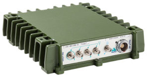
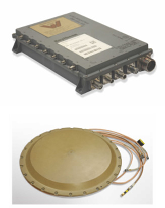
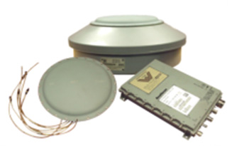
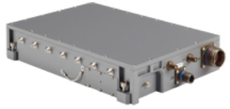
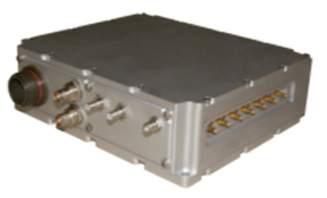
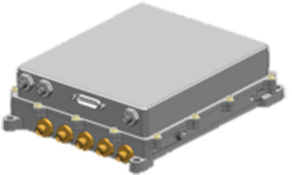
Peter Soar: “The GAJT-710 series are retrofittable GPS anti-jam products that combine a seven-element controlled reception pattern antenna (CRPA) and the antenna electronics in a single unit. The GAJT-AE-N is a GPS anti-jam antenna electronics system that supports a separated four-element antenna.”
Photo: NovAtel
Photo: NovAtel
Photo: NovAtel
Main features: “All three products protect the GPS L1 and L2 bands simultaneously, and are suitable for military (SAASM) receivers as well as open-signal receivers, normal civil receivers and ‘survey grade’ receivers. The wideband design means that the units are ready for M-code. In the GAJT-710, there are seven antenna elements for up to six independent nulls on both frequencies, and the GAJT-AE-N supports four antenna elements, for up to three independent nulls. All products use space-frequency adaptive processing for increased degrees of freedom. System messages provide an indication of jamming presence, even when the nulling is defeating the jamming.”
Intended market: “GAJT-710ML is optimized for land use, while GAJT-710MS is used for maritime and littoral applications. Both types are currently in use on mobile platforms and fixed installations. The GAJT-AE-N is optimized for smaller platforms such as unmanned air vehicles, and is currently in use on a variety of platforms. GAJT products have been shipped to customers in 16 countries to date.”
Example customers: “The GAJT-700ML (a predecessor to the 710ML) was selected for trials by the Canadian Army through the Build in Canada Innovation Program, with exercises performed on the Artillery Observation Post Vehicle (LAV III OPV). Both GAJT variants were selected for field testing by the U.S. Army Communication-Electronics Research Development and Engineering Center (CERDEC) through the U.S. Army Rapid Innovation Fund. The United States Naval Observatory (USNO) selected the GAJT-710ML to satisfy a requirement at sites throughout the Department of Defense Information Network (DoDIN). The GAJT-AE-N is deployed on the Schiebel Camcopter S-100, and was also selected for testing on the M777C1 Howitzer by the Canadian Army.”
Situation with regards to export: “All GAJTs are designed and built in Canada. As such, they are subject to the Controlled Goods Program of Canada, but they are free from ITAR for non-U.S. customers.”
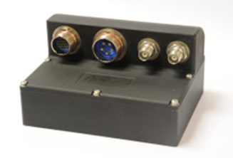
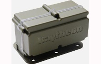
Raytheon UK
Some Raytheon products were mentioned briefly in the April column; I caught up with Alan Wright, business development executive, Force Protection, to get the latest information.
Alan Wright: “Raytheon UK offers a range of anti-jamming products ranging from high-performance products with multiple-element CRPAs to low size, weight and power products. Our current product lines utilize either analog or digital technologies to suit specific end-user requirements.”
Product
Image
Key Features
GAS-1
Analog technology, 7 antenna elements, switchable L1/L2 protection, minimal quiescent time delay, nulling, J/N, M-code signal bandwidth, AE/antenna integrated variant, fiber optic output variant.
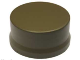
Digital technology, 5 antenna elements, simultaneous L1/L2 protection, low size, weight & power, STAP, nulling, J/N, direction finding, anti-spoof, jamming flag, M-code signal bandwidth.
Landshield
Digital technology, integrated 4-element antenna, simultaneous L1/L2 protection, low size, weight and power, STAP, nulling, J/N, direction finding, anti-spoof, jamming flag, M-code signal bandwidth, switched antenna variant.
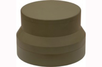
MiniGAS
Analog technology, integrated 4-element antenna, simultaneous L1/L2 protection or L1 with L2 passthrough, low size, weight and power, minimal quiescent time delay, nulling, jamming flag.
MicroGAS
Analog technology, integrated 2-element antenna, simultaneous L1/L2 protection, very low size, weight and power, minimal quiescent time delay, nulling.
Intended market: “With over 25 years’ experience, Raytheon UK is a world leader in the development, production and supply of GPS Anti-Jamming (GPS-AJ) systems to the majority of the world’s military forces (including the U.S. DoD and UK MOD), with solutions developed and certified for air, maritime and land applications. Raytheon UK has designed and manufactured in excess of 10,000 GPS anti-jam units for the worldwide market.”
Situation with regards to export: “GAS-1, ADAP and SAS are subject to U.S. ITAR restrictions. Landshield, MiniGAS and MicroGAS are free from ITAR and subject to UK export control.”
Rockwell Collins
I spoke with Al Simon, business development for navigation products/solutions, to get the latest on Rockwell Collins’ offerings. Rockwell’s portfolio includes some CRPA products aimed specifically at weapons. Al kindly provided the following table to summarize:
Product
Image
Platform
Key Features
Integrated GPS Anti-Jam System (IGAS)
Weapons (Embedded)
GPS receiver + AJ, nulling and beamforming, spatial, 20 in3, <2 lbs, up to 4 RF antenna inputs, 90+ dB J/S performance *, GPS (simultaneous L1 & L2), path to M-code
Strategic Anti-Jam Beamforming Receiver (SABR)
Weapons (Embedded)
GPS receiver + AJ, nulling and beamforming, STAP, 46 in3, <3 lbs, up to 7 RF antenna inputs, 120+ dB J/S performance*, GPS (simultaneous L1 & L2), path to M-code
NavStorm+
Weapons
Nulling, spatial, 6.9 in3, <.6 lbs, up to 5 RF antenna inputs, 20,000 G shock, 90+ dB J/S performance*, GPS (simultaneous L1 & L2), path to M-code
NavFire
Weapons
Nulling, spatial, 2 in3, <.2 lbs, 1 or 2 RF antenna inputs, 25,000 G shock, 85+ dB J/S performance*, GPS (L1 or L2), path to M-code
DIGAR-200
Airborne, Maritime, Ground
Nulling and beamforming, spatial, 218 in3, <11 lbs, up to 7 RF antenna inputs, 110+ dB J/S performance*, GPS (simultaneous L1 & L2), path to M-code
DIGAR-300
Airborne, Maritime, Ground
Nulling and beamforming, STAP/SFAP, 69 in3, <5 lbs, up to 7 RF antenna inputs, 125+ dB J/S performance *, GPS (simultaneous L1 & L2), path to M-code
Small Platform AJ (Pre-Production)
Ground, Airborne
Nulling and beamforming, STAP/SFAP, 45 in3, <3 lbs, up to 7 RF antenna inputs, 95+ dB J/S performance*, GPS (simultaneous L1 & L2), path to M-code
STAP (Space Time Adaptive Processing); SFAP (Space Frequency Adaptive Processing)
* Beamsteering mode. Actual performance is classified
Situation with regards to export: All listed products are unclassified, but are subject to U.S. ITAR restrictions.
Roke Manor Research
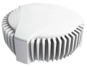
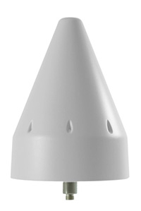
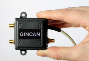
This column wouldn’t be complete without a few words on my own organization. Roke has been developing anti-jam CRPAs since the 1980s, but rarely offers its own products. Typically Roke develops bespoke anti-jam and anti-spoof technology for other defense organizations, including for some products already listed above. Examples of bespoke developments for more specialist markets include Gincan and the Helium antenna.
Photo: Roke
Photo: Gincan
Main features: Both these products are aimed at the commercial civilian market, but do also have defense interest. The Gincan is a very basic low-cost CRPA, with just two antenna elements. The Helium is a conical spiral design, using four antenna elements, and is primarily aimed at protecting GNSS in critical infrastructure. The Helium has excellent low-elevation performance. Both antennas feature very low latency, making them particularly suitable for timing receivers.
Intended market: The Gincan is primarily aimed at providing a basic level of anti-jam capability to the automotive mass market, including cars and trucks, but also has been adopted by some lightweight UAV platforms. The Helium is aimed directly at timing receivers for critical infrastructure, including mobile base stations, digital TV networks, stock exchange and financial institutions, and power and utility grids.
Example customers: Gincan has been delivered to 42 countries, with a mixture of commercial, defense and national security customers. Helium is a relatively new product, and is being trialed on infrastructure in two countries.
Situation with regards to export: Both products are unclassified and suitable for commercial use. They are subject to UK export control as dual-use items, and are ITAR-free.
Others
There are many other suppliers of CRPA technology — unfortunately, too many to cover in this column. Mayflower Communications offer a good range of CRPA products in the form of their NavGuard range. Some other suppliers include Cobham Antenna Systems, BAE Systems Rokar, Thales, Harris Corporation, L-3 Interstate Electronics and Lockheed Martin. I encourage you to contact these companies for the latest information if you are contemplating a CRPA product. If you’re a CRPA supplier and I’ve missed you, please feel free to post a link to your products in the comments section below.
So, that was a bit of a whirlwind tour through some of the products currently around. CRPAs come in all shapes and sizes, and they all have their own particular characteristics and subtleties.
I conclude by reiterating my earlier point. Always conduct a threat analysis, seek the help of a navigation warfare expert if necessary, and properly evaluate your choices. Happy choosing!
Exploring IMU specifications and correlating them to performance of a final product can be daunting, as differences between MEMS sensors are not always apparent. This article presents achievable performances in fusion technology across a range of IMUs among the best in their respective performance categories.
The number of available options in inertial navigation systems (INS) has grown substantially over the last several years. Major advances have been made not only in inertial measurement unit (IMU) technology, but also in the ability to exploit sensor information to its fullest extent. In both cases, the largest impact can be seen in the micro-electrical-mechanical systems (MEMS) sensors. MEMS sensors are typically much smaller, lower power and less expensive than traditional IMUs. The net result of these improvements is a proliferation of INS systems at much lower cost than were previously available and, therefore, greatly increased accessibility to technology that has historically seen limited deployment. Selecting the appropriate sensor and fusion solution for a particular application can be very challenging due to the large and confusing spectrum of solutions.
The IMUs will be examined in the context of new enhancements to sensor fusion algorithms such as the use of INS profiles. The concept of INS profiles applies environment specific constraints to improve performance in certain types of vehicles, or motion profiles. External sensors such as odometers and dual antenna operation can also aid the solution considerably, but will be unused in this analysis except for occasional comparisons. These external aiding sensors are extremely helpful in many cases and are available to use with a proprietary tightly coupled GNSS+INS solution called SPAN, but this paper seeks to evaluate what performance can be achieved without such aids.
Real-world test results will be examined using a selection of IMUs with the latest SPAN algorithms to illustrate what kind of performance can be achieved with different sensors in difficult conditions. Despite their major advances over the past few years, there are many challenges involved with utilizing MEMS technology to provide a robust navigation solution, particularly during limited GNSS availability or low dynamics. The measurement error characteristics of these devices have improved dramatically, but are still much larger and more difficult to estimate than traditional sensors. Advancements in SPAN sensor fusion algorithms have enabled these smaller sensors to achieve remarkable performance, especially in applications where environmental conditions allow for additional constraints to be applied.
This testing focuses on the land profile, meaning the constraints applied to a fixed-axle vehicle. The test scenarios were selected in such a way as to provide results for ideal, poor and completely denied GNSS coverage.
INS Profiles
GNSS and IMU sensors are only one part of the overall INS system performance. The sensor fusion algorithms used to exploit the available sensor data to its utmost capability are equally as important. In this regard, several improvements have been made to the SPAN INS algorithms to enhance performance under a variety of scenarios.
The largest addition to the SPAN product line is the introduction of INS profiles. That is, environment- and vehicle-specific modeling constraints can be utilized to enhance the filter performance. For example, the land profile, which will be examined in depth in this article, is intended for use with ground vehicles that cannot move laterally. The assumptions introduced for land vehicles, however, are not necessarily valid for different forms of movement, such as those experienced by a helicopter. Therefore, profiles have been implemented via command, and controlled as required by the user, allowing for maximum performance depending on the application at hand.
The land profile is analogous to what has historically been identified as dead reckoning. It is a method that uses a priori knowledge of typical land vehicle motion to help constrain the INS error growth. In other words, it makes assumptions on how land vehicles move to simplify inertial navigation from a six-degree-of-freedom system to something closer to a distance/bearing calculation. The land profile takes the concept of dead reckoning, models it as an update type into the inertial filter and adds a few additional enhancements.
Velocity Constraints / Dead Reckoning. Amongst other optimizations, the land profile enables velocity constraints based on the assumption of acceptable vehicle dynamics. This includes limiting the cross track and vertical velocities of the vehicle. Of all the enhancements, this is the one most colloquially referred to as dead reckoning.
In its simplest form, dead reckoning is the propagation of a position without any external input. In this forum, external input generally refers to GNSS satellites. Without external input, dead reckoning is inherently dependent on assumptions of velocity and heading to propagate the position. These solutions have evolved by integrating inertial and directional sensors to provide more local input and improve the solution propagation. This also is not a perfect method, however, as inertial sensors have their own errors that grow exponentially over time. The land profile velocity constraints explain the bulk of optimizations SPAN has made to enable dead-reckoning performance in extended GNSS outage conditions.
Explaining the velocity updates involves using the current INS attitude (); the vehicle attitude ( ) is estimated by applying the measured or estimated IMU body to vehicle direction cosine ( ). From this, the pitch and azimuth for the vehicle is estimated.Using the magnitude of the measured INS velocity in conjunction with the derived vehicle orientation, the vehicle velocity is computed, allowing the expected vertical velocity and cross-track to be constrained.
A velocity vector update is then applied to the inertial filter to constrain error growth. The effects of this method are expected to be most apparent in extended GNSS outage conditions when the INS solution must propagate with no external update information.
Phase Windup Attitude Updates. Some applications are inherently difficult for inertial sensors due to the fact that these systems are reliant on measuring accelerations and rotations in order to observe IMU errors. When traveling at a constant bearing and speed, separating IMU errors from measurements becomes challenging, so any application that does not provide meaningful dynamics is more demanding on inertial navigation algorithms. This type of condition commonly appears in applications such as machine control, agriculture and mining.
Gravity is a strong and fairly well known acceleration signal, so the real difficulty in this type of environment is managing the attitude, and especially azimuth, errors. Attitude parameters become difficult to observe when the system experiences insignificant rotation rates about its vertical axis.
External inputs can be used for providing input during low dynamic conditions when rotational observations are weaker. These are particularly helpful in constraining angular errors and include the same types used to assist in initial alignment: dual antenna GNSS heading, magnetometers, etc. However, as the goal of this testing is to demonstrate the achievable performance from a single antenna GNSS system, this type of external aid was specifically omitted.
Utilizing a patented technique for determining relative yaw from phase windup, the system is able to distinguish between true system rotation and unmodeled IMU errors during times of limited motion. This is a novel way to extract additional information out of existing sensors rather than adding more equipment and complexity.
The phase windup update is used to constrain azimuth error growth during low dynamic conditions that are typically not favorable to inertial navigation. However, it does require uninterrupted GNSS tracking and is therefore applicable only in GNSS benign environments. This approach is expected to show the greatest benefit in low dynamic conditions and be directly attributable to azimuth accuracy, but only in conditions where GNSS availability is relatively secure.
Equipment and Test Setup
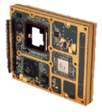
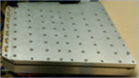
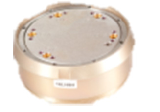
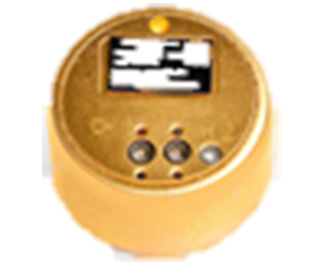
We paired OEM-grade GNSS receiver cards with a selection of IMUs in different performance categories. Since the OEM GNSS platform is capable of tracking all GNSS constellations and frequencies, we configured each receiver to use triple frequency, quad-constellation RTK positioning. The receivers were coupled with a wideband antenna capable of tracking GPS L1/L2/L5, GLONASS L1/L2, BeiDou B1/B2 and Galileo E1/E5b signals.
Three IMUs were tested: an entry-level MEMS IMU (UUT1), a tactical-grade MEMS IMU (UUT2) and a high-performance fiber-optic gyro-based IMU (UUT3).
All GNSS receivers and IMUs were set up in a single test vehicle and collected simultaneously for all scenarios. IMUs were mounted together on a rigid frame, and all receivers ran the same firmware build that were connected to the same antenna.
The tests were conducted using a single GNSS antenna with no additional augmentation sources, such as distance measurement instrument (DMI) or wheel sensor. These are extremely helpful in aiding the solution, but as previously mentioned, this testing seeks to demonstrate the possible performance without the benefit of additional aiding sources. Dependence on aiding sources is a very important distinction when comparing such systems.
The GNSS positioning mode used was RTK via an NTRIP feed from a single base station with baselines between 5–30 kilometers. This was done to try to minimize GNSS positioning differences between the three systems. L-band correction signals were not tracked, and PPP positioning modes were not enabled.
A basic setup diagram of each system under test can be seen in Figure 1.
FIGURE 1. Equipment set-up (not to scale).
Test Scenarios
Four test scenarios will be examined using all the equipment and algorithms described above. They are: urban canyon, low dynamics, parking garage and extended GNSS outage.
The urban canyon test is designed to show the performance of the system in restricted GNSS conditions. The challenge to this scenario is to maintain a high-accuracy solution when GNSS positioning becomes intermittent or even unavailable.
The low dynamics test is intended to illustrate the benefits of the land profile, and specifically the phase windup azimuth updates in maintaining the azimuth accuracy.
The parking garage test will show the efficacy of the velocity constraint models over the different IMU classes as the extended outage provides no external information to the INS filter whatsoever. Again, no other aiding sources were used.
Urban Canyon Test. The urban canyon environment has been and remains one of the strongest arguments in favor of using GNSS/INS fusion in a navigation solution. Because urban canyons are common, densely populated and, of course, a demanding GNSS environment, they represent both an important and challenging location to provide a reliable navigation solution. Typically, they contain major signal obstructions, strong reflectors and complete blockages (depending on the city). For this reason, they provide an excellent use case for INS bridging to maintain stability of the solution.
During most urban canyon environments, it is typically rare to incur total GNSS outages of more than 30 seconds. Therefore, this scenario examines the stability of the solution in continuously degraded, but not generally absent, GNSS. In this case, the coupling technique of the inertial algorithms rather than quality of the IMU dominates achievable position accuracy.
The receiver platform is capable of tracking all GNSS constellations and frequencies. This provides a significant benefit to test scenarios, such as the urban canyon, where the amount of visible sky is significantly restricted. In this case, the more satellites that are observable, the more the tightly coupled architecture can exploit the partial GNSS information.
Though position accuracy between IMUs is less apparent in this condition, attitude results remain separated by IMU quality, which is a major consideration for some mapping applications such as those using lidar or other sensors where a distance/bearing calculation must be done for distant targets.
Test data for this scenario was collected in downtown Calgary, Canada. The trajectory (Figure 2) includes several overhead bridges for brief total outages and some very dense urban conditions.
FIGURE 2. Urban canyon test trajectory.
Table 1 shows the RMS error results of the three systems running both the default and land profiles. The first thing to notice is that the errors are differentiated by IMU category, though the differences are fairly small in the position domain thanks to the tightly coupled architecture. However, because GNSS information is partially available, the differences seen in activating the land profile are fairly modest, especially as the IMU performance rises.
TABLE 1. RTK RMS errors for urban canyon.
As the clearest benefits of the land profile are seen on the entry-level MEMS IMU (UUT1), these will be explored graphically in Figures 3 and 4. Figure 3 shows the position domain, and the RMS differences can be seen in a few cases where the default mode errors increased faster than the land profile. An example of this divergence is most obvious around the 1500-second mark of the test during periods GNSS is most heavily blocked.
FIGURE 3. UUT1 position error (std vs. land). Source: GNSS
FIGURE 4. UUT 1 attitude error (std vs. land). Source: GNSS
Low Dynamics Test. The low dynamics test is designed to emulate conditions experienced by machine control, agriculture and mining applications. In this situation, GNSS availability is generally not the limiting factor and can be used to control the low frequency position and velocity errors of the INS system. The difficulty is managing the attitude, especially azimuth, errors because attitude parameters are very hard to observe without significant rotations or accelerations (Figures 5 and 6).
FIGURE 5. Low dynamics test trajectory. Source: GNSS
FIGURE 6. Low dynamic UUT1 position errors. Source: GNSS
The low dynamics test was collected in an open-sky environment and consisted of traveling in a straight line on a rural road for roughly 2 km at an average speed of 10–15 km/h.
As this type of scenario provides little physical impetus, the azimuth and gyroscope biases are not observable. The reason for this is due to the use of the first-order differential equations to estimate the navigation system errors. Essentially, the differential equations define how the position, velocity and attitude errors change (grow) over time based on each other and the IMU errors. The observability of a particular update is tied to additional states through the off-diagonal elements of the derived transition matrix with the accelerations and rotations experienced by the system.
The overall RMS solution errors for RTK are provided in Table 2. As evident by the results presented, the position and velocity errors are clearly constrained by the continuous RTK-level GNSS position regardless of whether the land profile is enabled or not. The real differentiator in the land profile is the attitude performance due to the use of phase windup as a constraint. Moreover, the attitude improvements are certainly tied to IMU quality.
UUT1 exhibited a noticeable improvement in the attitude performance, while the higher performance IMUs did not. This is not entirely unexpected as the precision of the phase windup is lower than that of the higher grade IMUs.
Looking at the data graphically, Figure 7 shows the effect of land profile on positioning performance in this scenario. The two solutions are indistinguishable on the plot, and are all within standard RTK-level error bounds as was indicated in the RMS table.
Figure 7 shows the attitude accuracy with and without the land profile enabled. Again, the largest gains are seen on the entry-level UUT1, so this is the graphic shown below. This shows how the error peaks of the azimuth estimates are constrained. All the sharp corrections in each plot correspond to the vehicle turning around at the end of each 2-Km line and illustrates how much more powerful a rotation observation can be in azimuth accuracy overall.
FIGURE 7. UUT1 attitude error (std vs. land).
Parking Garage Test. This test was carried out at the Calgary International Airport and was selected to show the INS solution degradation during extended complete GNSS outages. The test consisted of an initialization period in open sky conditions to allow the SPAN filter time to properly converge, followed by a 500-second period within the parking garage. During the interval within the parking garage there were no GNSS measurements available.
Figure 8 provides a trajectory of the test environment. The time spent inside the parking structure is evident on the center bottom of the image.
FIGURE 8. Parking garage test trajectory.
Unlike urban canyon environments that contain partial GNSS information, this exhibits an extended period of complete GNSS outage. During this type of scenario, the IMU specifications become much more significant. IMU errors directly translate to the duration the solution can propagate before the accumulated low-frequency errors of the IMU grow to unacceptable levels. System performance during the outage degrades according to the system errors at the time of the outage and the system noise. The velocity errors increase linearly as a function of attitude and accelerometer bias errors. The attitude errors will increase linearly as a function of the unmodeled gyro bias error. The position error is a quadratic function of accelerometer bias and attitude errors.
Position results from each IMU are shown for UUT 1 in Figure 9. This plot shows the error with the land profile on and off. Without the land profile, the second-order position degradation in an unconstrained system is clearly visible.
FIGURE 9. UUT1 position error (std vs. land ).
By enabling the land profile, the filter constrains IMU errors by utilizing a velocity model for wheeled vehicles. With the constraints, the position errors are startlingly reduced for UUT1 and then progressively less impactful as the IMU quality increases in UUT2 and UUT3, respectively. This makes sense as the IMU error growth is progressively smaller in those IMUs, so the effect of mitigating them is also reduced.
Extended GNSS Outage Test. An extension of the parking garage test is to evaluate the performance in a much longer outage. Instead of 10 minutes, an outage of one hour was tested. Also, due to the extremely long GNSS outage bridging, the effects of adding a DMI sensor (odometer) will also be explored as they are able to be used as a major additional aiding source.
The most common measure of dead-reckoning performance is error over distance traveled (EDT). Due to the very long duration outages in this test, the errors will be reported in error over distance traveled to conform to the typical reporting method. This test was conducted in a mixture of highways and suburban streets with an average speed of 65 Km/h, incorporating a moderate amount of dynamics.
This effect can be seen over the duration of the entire outage as well in Figure 9. In this case, the points are the RMS error over several tests. and the light background shroud represents the one-sigma confidence as time progresses. The confidence increases over time as the overall distance traveled also increases.
FIGURE 10. Land profile EDT with and without DMI aid over 1-hour GNSS outage.
Results and Conclusions
In testing a range of IMUs in some challenging scenarios, this paper has sought to illustrate what kind of performance is achievable using each kind of system. An added complexity is looking at what effect certain inertial constraint algorithms have on this solution.
Although low-cost MEMs IMUs are continuing to greatly improve in quality and stability, the end application is still highly correlated to the overall performance of a selected INS system. For a great many applications, the MEMS devices in combination with a robust inertial filter can meet requirements and provide excellent value. However, some applications continue to require higher end sensors, and possibly post-processing to meet their needs.
The ability of SPAN to utilize partial GNSS measurements such as pseudorange, delta phase and vehicle constraints means even low-cost MEMs are capable of providing a robust solution in challenging GNSS conditions. However, this tightly coupled integration is limited in cases where GNSS is completely denied or when in low dynamic conditions.
INS profiles using velocity constraints, phase windup and robust alignment routines have been shown to provide substantial aid to the INS solution in tough conditions, such as GNSS denied or low dynamics. These improvements were shown to exhibit greater impact as the IMU sensor precision decreases. These abilities, in conjunction with the existing tightly coupled architecture of SPAN and the ever-increasing accuracy of MEMS, IMUs indicate that robust GNSS/INS solutions will continue to proliferate at lower cost targets. However, very precise applications such as mapping will continue to rely on higher quality sensors to meet strict accuracy requirements.
ACKNOWLEDGMENTS
The authors thank Trevor Condon and Patrick Casiano of NovAtel for collecting and helping to process the data presented in this article, and to Sheena Dixon for her tireless editing.
Manufacturers
NovAtel SPAN technology on the NovAtel OEM7 receiver is the testing and development platform for this research. NovAtel OEM7700 GNSS receiver cards and a NovAtel wideband Pinwheel antenna were employed. The inertial units under test were an Epson G320 (low-power, small-size MEMS IMU); Litef μIMU-IC (larger tactical-grade performance IMU still based on MEMS sensors); and a Litef ISA-100C (near navigation-grade IMU using fiber-optic gyros (FOG). Although all are excellent performers in their class and capable of providing a navigation-quality solution, the intent is to show the potential limitations that might arise due to the intended application.
RYAN DIXON is the chief engineer of the SPAN product line at NovAtel Inc., leading a highly skilled team in the development of GNSS augmentation technology. He holds a BSc. in geomatics engineering from the University of Calgary.
MICHAEL BOBYE is a principal geomatics engineer at NovAtel and has participated in a variety of research projects since joining in 1999. Bobye holds a BSC. in geomatics engineering from the University of Calgary.
Taoglas has launched Axiom, a reference design for a low-profile, compact multiple-antenna solution for the next generation of connected cars. Taoglas is a provider of GNSS, automotive and Internet of Things products.
The reference design will help automobile manufacturers overcome one of the biggest challenges of the connected car: where and how to place the multitude of antennas needed for maximum performance.
As many as 18 antennas are needed to power the next-generation connected car, including
multiple cellular antennas for network connectivity;
Wi-Fi for hotspot connectivity;
GNSS for navigation, emergency call systems and other location-based technologies;
satellite radio;
AM/FM antennas;
radar antennas for object detection;
Bluetooth antennas for smartphones and other devices, and
dedicated short-range communications (DSRC) antennas for vehicle-to-vehicle/infrastructure applications.
Locating these antennas in a vehicle in close proximity to each other and additional electronics systems while minimizing interference and maximizing performance is extremely challenging from a design and RF performance perspective.
Manufacturers also need to take into consideration both ease of installation and assembly, and antenna size to determine how they would best work with the vehicle’s aesthetics. Taoglas has worked with the automotive industry for more than a decade, providing antenna solutions to many of the major tier 1 automobile OEMs across the globe.
The Axiom reference design incorporates Taoglas’ wealth of knowledge and expertise gained over the years into a roadmap to help automobile manufacturers more quickly advance antenna configurations that work for their particular make and model.
“Getting that many antennas to work efficiently in a small space at a competitive cost is the number one challenge for the RF teams of automobile manufacturers,” said Dermot O’Shea, co-CEO of Taoglas. “While every car manufacturer will require a slightly different solution, having a multi-antenna reference design to work from allows them to see what they can do in terms of placement and size, and how that impacts performance — all without waiting months for a custom solution to test. They can take the prototype and test it in the field to prove out concepts. Using Taoglas’ Axiom reference design allows them move more quickly to market with solutions that work. We can also work with Tier 1 OEMs to integrate the elements of the Axiom antenna reference design quickly and efficiently directly onto the board of their telematic control units, achieving highest radiated power and sensitivity, while minimizing project time, cost and size, all in one single package.”
Taoglas’ Axiom reference design has integrated nine antennas, including:
LTE Antennas: Four LTE antennas, each operating from 698 MHz to 6 GHz to fully cover LTE worldwide application bands.
Wi-Fi Antennas: Two Wi-Fi elements, supporting both 2.4 GHz and 5.8 GHz bands for Wireless Local Area Network.
GNSS Antenna: An active GNSS element to support GPS, GLONASS and BeiDou navigation systems. L1/L2 options available.
SDARS Antenna: One SDARS element to support satellite radio applications.
DSRC Antenna: One DSRC element, which supports V2V/V2X dedicated short range communication.
Taoglas’ advantage is its ability to integrate all of the antennas required for the connected car in a confined space and maintain maximum performance. The Axiom reference design uses a compact PCB all with SMT-mounted components, and also incorporates a unique board-to-board connector option, allowing the antennas and electronics systems to coexist in a single space inside the vehicle, with no RF cables or additional connectors required.
The Axiom reference design also helps auto manufacturers simplify manufacturing and assembly, with surface-mount solutions that feature the temperature and vibration resistance with the quality standards that manufacturers require. Installation is clipping the PCB into the telematics board.
Sokkia has introduced a pair of software solutions for its total stations, robotics and GNSS rover systems — GeoPro Field and GeoPro Office.
Sokkia GeoPro Field software.
GeoPro Field provides a graphical user interface designed to collect field measurements for land surveying and construction activities.
“End-users needing a field tool to collect and import measurement data into design and drafting software will find GeoPro Field to be a fast and accurate method that will increase productivity with CAD functionality in the field,” said Ray Kerwin, director of global surveying products. “A key to GeoPro Field is its compatibility with various software workflows — point files are easily exported to third-party software.”
Sokkia GeoPro Office software.
Sokkia GeoPro Office is the office-processing complement to the field software — designed to clean, process, and analyze field data into its easiest-to-use form. “Users will immediately see the benefit in time saved, when compared to a variety of traditional manual methods,” Kerwin said.
The office software can also be expanded with an optional 3D and road design module, for further versatility to design roads with the processed field measurements.
“The Sokkia GeoPro Field and Office have user-friendly graphical interfaces, with simple in-field functions and office workflows. The user can get to work quickly due to the intuitive interface and simplicity of operation without the need for advanced training,” Kerwin said.
The European Space Agency (ESA) has signed a contract with Thales Alenia Space for an upgrade to Europe’s EGNOS satellite navigation augmentation system, which underpins the safety-critical use of satnav across Europe, according to ESA.
Designed by ESA and being exploited by Europe’s GNSS Agency (GSA), the European Geostationary Navigation Overlay Service (EGNOS) improves the precision of GPS signals over most European territory, while also providing continuous and reliable updates on the “integrity” of these GPS signals.
A network of ground monitoring stations throughout Europe performs an independent measurement of GPS signals, so that corrections can be calculated, and then passed to users immediately via a trio of geostationary satellites.
The result is that the EGNOS-augmented signals are guaranteed to meet the extremely high performance standards set out by the International Civil Aviation Organisation standard, adapted for Europe by Eurocontrol, the European Organisation for the Safety of Air Navigation.
Paul Verhoef, ESA director of the Galileo Program, and Philippe Blatt, VP Thales Alenia Space France, sign on June 6 a contract for an upgrade of EGNOS.
Paul Verhoef, ESA’s director of the Galileo programme and navigation-related activities, signed the contract at ESA Headquarters in Paris with Philippe Blatt, vice president of Thales Alenia Space France.
ESA is performing the procurement of EGNOS Version 2.4.2 under the overall program authority of the GSA, which oversees both EGNOS and Europe’s Galileo satellite navigation system.
Two upgraded EGNOS releases will be provided over the course of the development: EGNOS V2.4.2I and EGNOS V2.4.2A.
The releases will resolve various obsolescence issues related to EGNOS’s central processing facility, based in Toulouse, France — which generates the corrections and integrity information to be broadcast across the European continent — to ensure continuity of EGNOS services into the future, including safety-of-life services, to an ever-expanding community of users.
The new contract includes:
a refreshment and enhancement of the Central Processing Facility design without algorithm modification
an optimized qualification process
a guarantee of full compliance to safety-critical software development requirements
the performance of end-to-end verification activities extending to the three geostationary satellites used by the system
ensuring compliance to a new set of technical requirements and international standards.
Microsemi Corporation has updated the hardware on its TimeProvider 5000IEEE 1588 Precision Time Protocol (PTP) grandmaster clock. The update enables the clock to support Internet Protocol version 6 (IPv6) and multi-GNSS constellations to ensure better reception and higher security in a wide variety of telecommunications network applications.
“As our global wireless customers drive mobile infrastructure forward with LTE-Advanced (LTE-A) and 5G services, support for IPv6 and alternate GNSS constellations is rising in importance for deploying a robust, secure and future-proof synchronization network,” said Barry Dropping, senior director of product line management for Microsemi.
“The addition of GLONASS and Galileo support on the TimeProvider 5000 system greatly enhances the robustness and security of this widely adopted synchronization platform for global carriers,” Dropping said. “We will continue to invest in this technology to ensure reliable long-term roadmap support is provided for telecommunications customers.”
An increasing number of global operators are now looking at solutions such as Microsemi’s enhanced TimeProvider 5000, because the device offers multiple constellations in accordance with the directives in certain countries to remove their sole dependency on GPS. Having support for GLONASS and Galileo constellations also makes systems more robust and secure to certain GNSS vulnerabilities.
Microsemi’s TimeProvider family has been installed in more than 350 networks across the globe, enabling communications service providers to build stable, high performance and reliable network infrastructures.
Along with new support for IPv6 and multi-GNSS constellations, the recently enhanced TimeProvider 5000 provides redundant hardware, user configurable PTP profiles and Synchronous Ethernet (SyncE) support with optical small form-factor pluggable (SFP) modules.
The TimeProvider 5000 is a carrier-grade IEEE 1588 PTP grandmaster clock with a Network Time Protocol (NTP) server option and expansion shelf capabilities that include SyncE and an advanced PTP profiles, making the timing and synchronization system capable of supporting network needs today and in the future. Its flexible design is vital to enable circuit to packet network migration for high-speed data services and wireless backhaul, and to deliver 3G, 4G/LTE, LTE-A and 5G wireless services.
Microsemi’s TimeProvider family is a part of the carrier routing and switching equipment market, which was approximately $43 billion in 2016 according to market research firm IHS Infonetics. The firm also expects this market to see sales growth as more carriers start and expand their 4G services along with the introduction of 5G deployments toward the end of 2019.