The MQ-9 Reaper drone. (Photo: U.S. Air Force/Paul Ridgeway)
A small aircraft’s encounter with a likely military drone near Edwards Air Force Base resulted in navigation failure, according to a report filed with NASA’s Aviation Safety Reporting System.
In October 2019, a single engine Piper P-46 Malibu was flying at 24,000 feet 36 miles north of Los Angeles en route San Diego.
Defense drone overhead
The pilot reported, “I saw a DOD drone (inverted V tail) pass overhead approximately 1,000 [feet] above. At the same time, my PFD [primary flight display] indicated that I had a large magnetic variation error, and in turn … indicated that I was now flying to a new way point (TCH VOR) located in Utah, well off my flight plan.”
Later, the navigation system indicated that the aircraft was on its way to a spot in Montana.
Interestingly, the flight plan displayed by another cockpit instrument, the Multi-Function Display, was not affected.
The aircraft had been operating under an Instrument Flight Plan. Federal Aviation Administration rules for light aircraft allow such operation with GPS as the sole navigation sensor.
With the primary flight display not operating properly, the aircraft was no longer able to fly a safe instrument approach to landing. Fortunately, the weather was such that it could proceed and land using Visual Flight Rules.
In the pilot’s words, “Had it not been a VMC [visual meteorological conditions] day allowing me to fly a visual approach, I would have had to [advise Air Traffic Control] – and find a way to land without any reliable approach capability.”
A combination of factors
The general consensus among experts is that this incident was inadvertent and likely arose from a combination of factors. Most significant were that the drone flew above the light aircraft, temporarily blocking some GPS signals, and emitting electromagnetic radiation from one or more of its on-board systems.
It is not possible to say what those systems and radiation may have been. It is unlikely they were intended to interfere with GPS reception, as that would pose serious safety-of-flight concerns in the nearby congested Los Angeles airspace.
GPS signals are infamously easy to disrupt, though. It is probable that the close proximity of the drone resulted in some radiation from its systems “spilling over” into GPS frequencies and causing the problem.
Of greater concern is that the light aircraft’s systems did not quickly reset and recover once the drone had moved off and the interference ceased. Had the aircraft been flying in the clouds or bad weather, the loss of its only radionavigation source could have been quite serious.
While not clear from the report, it is likely that the navigation system only recovered after a complete shutdown and restart. From the report in the NASA database:
“The system has since been checked and is operating correctly, but it seems pretty clear this was some type of interference / jamming arising from the DOD drone. Clearly, this is a significant risk to all aircraft, and because if [sic] occurred within the LA airspace it is a serious threat to safe flights.”
The need to address interference
Shortly before this incident, the International Civil Aviation Organization identified addressing interference with satellite navigation system signals an “urgent priority.” This was in response to concerns from several member countries and organizations citing safety of flight issues. One example cited was the near loss of a passenger aircraft flying in the mountains during a period of GPS disruption.
The October 2019 report of interference from the drone is number ACN 1696794 in the NASA Aviation Safety Reporting System. It can be accessed by searching here.
ADVA has launched a centralized GNSS monitoring and assurance tool that uses artificial intelligence (AI) and machine learning (ML) for comprehensive predictive maintenance.
The new customer-owned tool enables users to collect and analyze huge amounts of information from across the network to remotely identify issues and protect networks from GNSS vulnerabilities, including jamming and spoofing attacks.
It also helps to identify GNSS obstruction issues, detect blind/poor spots that appear over time, and enable optimal antenna positioning.
Built into ADVA’s Ensemble Controller network management suite with Sync Director, the solution enables customers to detect potential problems in advance, maintain the highest quality of network synchronization and significantly reduce opex. By complementing today’s limited distributed approach to GNSS assurance with a centralized-global system, it offers a major boost to critical infrastructure dependent on satellite-based timing.
“What we’re offering is a way for network operators to see the bigger GNSS picture. Using AI and ML to analyze the entire synchronization network, our centralized GNSS monitoring and assurance solution will be key in the fight against GNSS cyber issues, such as jamming and spoofing attacks,” said Gil Biran, general manager, Oscilloquartz, ADVA.
“This new technology provides the power to proactively tackle issues that jeopardize vital services,” Biran said. “Harnessing the capabilities of our synchronization devices to identify spoofing problems, it intelligently mines a wealth of data and gives network operators the precise info they need in a highly accessible way. By using long-term heat maps and enormous amounts of data from a wide range of GNSS receiver sources, our solution identifies patterns and preempts issues. It alerts maintenance teams to obstructions or jamming conditions so that countermeasures can be put in place well before services are affected.”
As part of the network infrastructure, ADVA’s centralized GNSS assurance and monitoring solution enables a network-wide view of GNSS receiver health. Requiring no additional hardware or site visits, it remotely delivers detailed analysis, automatically detecting abnormal patterns with a patent-pending algorithm.
Utilizing AI and ML, it alerts maintenance teams to potential GNSS service degradation and safeguards against spoofed signals. Network operators receive updates through a user-friendly GUI as well as regular reports tailored to individual criteria.
As a component of ADVA’s comprehensive Ensemble Controller suite, the new technology makes synchronization monitoring and assurance an integral part of overall network management and control. For network operators, having a single system to track inventory simplifies operations and helps bolster network security.
“GNSS is the fundamental source of network time, phase and frequency generation across so many of today’s industries. From IT to telecommunications, from energy to finance, the reliability of satellite-based timing is crucial and the cost of interference is huge. This latest launch is a key part of our ongoing mission to remove the risk of GNSS vulnerabilities,” said Nir Laufer, senior director, product line management, Oscilloquartz, ADVA.
“The new solution joins our multi-band, multi-constellation GNSS receiver technology — which overcomes ionospheric delay variation — as well as our range of grandmaster clocks with network-based timing and outstanding holdover capabilities,” Laufer said. “Combined with our highly stable cesium clock technology, these create our ePRTC solutions for ultimate GNSS backup. With our comprehensive portfolio, all industry verticals are guaranteed accurate, cost-effective and highly resilient timing.”
CP Aeronautics offers American-built combat-proven unmanned aerial systems for defense, homeland security and civil applications
CP Technologies has launched a new division, CP Aeronautics, to provide integrated turn-key solutions based on unmanned aerial systems (UAS) platforms, payloads, data links, ground control stations (GCS) and communications for defense and civil applications.
Designed as leading-edge UAS-based solutions, CP Aeronautics’ systems offer operationally proven solutions for intelligence, surveillance and reconnaissance (ISR) systems requirements. CP Aeronautics’ broad product portfolio has demonstrated excellent performance and operability in demanding environments, the company stated in a press release. Backed by continuous research and development, these systems are built on three decades of technological and operational experience.
“Through our in-house capability as a UAS manufacturer and integrator with specialist subsidiaries and technology partners, we offer a complete range of subsystems including air vehicles, inertial navigation and avionics, electro-optical payloads (EO), communications, propulsion systems, launch and retrieval systems, command and control units,” said Brad Pilsl, vice president of business development at CP Aeronautics. “We also offer high-end training solutions for our partners and customers.”
CP Aeronautics will support government and commercial customers with the entire infrastructure necessary for development, production, integration, flight-testing, certification and operational support of UAS throughout their service.
The combat-proven operational systems include:
Orbiter 2 Small-UAS (SUAS)
Orbiter 3 Small Tactical UAS (STUAS)
Orbiter 4 Small Tactical UAS (STUAS)
Aerostar Tactical UAS (TUAS)
Dominator XP (MALE UAS)
Pegasus 120 high-performance multi-mission vertical takeoff and landing (VTOL) UAS
Specifically, Booz Allen’s work will aid in the development and modernization of GPS systems through major programs such as Military GPS User Equipment (MGUE), GPS III and Next Generation Operational Control System (OCX).
The NIWC Pacific Positioning, Navigation, and Timing (PNT) Division is the Navy’s principal research and development center for navigation sensors and systems.
SMC is the center of technical excellence for developing, acquiring, fielding, and sustaining resilient and affordable military space systems.
With this contract, Booz Allen will continue to serve as a key mission partner for NIWC Pacific and SMC on the important endeavor of modernizing PNT systems for U.S. and Allied warfighters.
To execute this highly complex scope of work, Booz Allen will provide a range of essential services, including system definition, requirements synchronization, capability improvement, cybersecurity engineering, platform integration and testing, and acquisition program management.
“Booz Allen’s robust track record of work in both systems engineering and cybersecurity continues to inspire trust from our clients,” said Vice President Brian Zimmermann. “Our deep bench of leaders and technical experts reassures our clients that no project is too big or too complex. It’s our privilege to help the Navy and Air Force modernize GPS systems that are so vital to the security of our nation.”
Read more about Booz Allen’s work with PNT systems here.
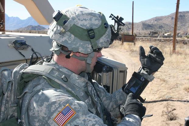
Staff Sgt. Reag Wood of 1st Combined Arms Battalion, 5th Brigade, 1st Armored Division, illustrates how he uses an iphone to obtain a visual image of a mock with insurgent activity during a field training exercise at White Sands Missile Range, N.M. (Photo: U.S. Army/Lt. Col. Deanna Bague)
An accuracy test of the Locata Network — a non-GPS-based positioning system installed at the U.S. Air Force White Sands Missile Range in New Mexico — focused on timing down to the nanosecond, with impressive results.
In 2018, the 746th Test Squadron (746 TS) tested its Non-GPS-Based Positioning System (NGBPS) at White Sands Missile Range as an alternative to GNSS for precise time transfer and synchronization. This was the first independently measured and characterized testing program for the NGBPS, which leverages Locata’s radio-based position, navigation and timing (PNT) technology to achieve high accuracy independent of GPS.
Using specific parameters and equipment configurations, independent experts proved Locata’s absolute and relative time synchronization and frequency stability performance. Under testing, the NGBPS provided exceptional time transfer and frequency stability across large areas.
With these successful results in hand, the U.S. Department of Defense will be able to leverage this capability for programs requiring high-precision time and frequency distribution, without relying on GPS alone. Plus, the system is flexible — Locata’s area of transmission can be increased to cover substantially larger areas than at White Sands for safety-of-life, military or government-mandated systems.
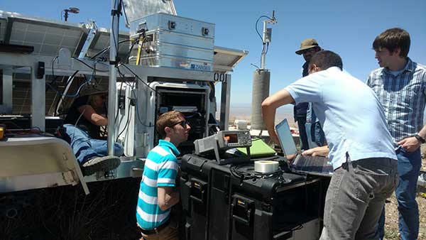
With USNO personnel, members of the 746 TS reconfigure the Master LocataLite site for the test. (Photo: 746 TS/USAF)
Background
Over the past two decades, the free availability of GPS time has enabled a plethora of time-dependent applications. Time and frequency synchronization between remote locations is crucial for digital communication systems, electrical power grids and financial networks, to name a few. Military operations also require accurate and reliable time information. Typically, these applications require accurate time synchronization ranging from 10 microseconds (μs) down to 100 nanoseconds (ns). Yet, while our critical reliance on GPS for time transfer continues to escalate, GPS remains susceptible to interference, disruption or denial.
A technician with the 746 TS re-aims a LocataLite antenna for an alternative TimeLoc configuration. (Photo: 746 TS/USAF)
Locata. Locata Corp., a privately owned Australian company with a U.S. subsidiary, invented a radio-location technology that provides precise PNT for environments where GPS coverage is unavailable. Locata ground-based PNT technology delivers positioning that, in many scenarios, far exceeds the performance and reliability of GPS. LocataNets, the company’s terrestrial networks, function as local ground-based replicas of traditional GPS position and timing services. They can be designed to reliably deliver a powerful, controllable, tailored signal as user applications require.
A LocataNet consists of synchronized LocataLite transceivers, all-in-one units that transmit and receive out of the same 10 x 5 x 1-inch box. Cables are connected to antennas for signal reception and transmission. Locata Rovers are mobile receivers within the network that use these synchronized LocataLite signals to calculate an accurate PNT solution.
The 746 TS employs the basic LocataNet laydown — multiple Slave LocataLites receive signals from a single Master LocataLite transceiver. The patented process by which slaves are synchronized to the master (or other slaves) is known as TimeLoc.
Until these new tests were run, the squadron’s attention had primarily been focused on the high-accuracy use of Locata’s position and navigation solution as an alternative to GPS when it is jammed, deceived or unreliable. But because all LocataLites are precisely synchronized via TimeLoc, network synchronization is a natural extension of Locata technology’s core capabilities.
In October 2015, GPS World reported that the United States Naval Observatory (USNO) showed LocataLites are a viable option for a stable 1 pulse per second (1 pps) distribution setup within an urban environment, where it can support applications such as cell-tower synchronization in GPS-challenged environments. The USNO tests demonstrated synchronization of less than 200 picoseconds — significantly better than any other known wireless network synchronization methodology, including GPS. If clear line-of-sight is available between a master and Slave LocataLite, precision is 50 picoseconds with frequency stability to 1×10-15 —better than a Stratum One atomic clock.
Because of the USNO’s timing expertise and familiarity with Locata TimeLoc testing, the 746 TS tasked the USNO to conduct independent synchronization experiments at White Sands, with the following objectives:
Evaluate the Locata master, slaves and non-Locata timing receiver at the master site in reference to USNO master atomic clock time.
Determine the Locata network’s internal, independent synchronization stability and accuracy.
Determine the Locata Rover’s 1 pulse per second (PPS) time stability and accuracy, for use in time transfer applications.
The primary purpose of the tests was to show that nanosecond-level time transfer is possible over significantly wide areas by using Locata, and that TimeLoc technology offers a relatively easy means of supporting exceptionally high-precision time and frequency distribution over large broadcast areas.
Slave LocataLite site layout. (Photo: 746 TS/USAF)
Synchronization Method
Since Locata technology was originally developed as an RF-based high-precision non-GPS-based positioning and navigation system, the time synchronization accuracy requirements for a LocataLite transceiver are very high. If centimeter positioning precision is desired for a Locata receiver, every small fraction of a second is significant; for instance, a 1-ns error in time equates to an error of approximately 30 centimeters (because of the speed of light).
TimeLoc is a patented high-accuracy wireless synchronization method developed by Locata Corp. It allows LocataLites to achieve high levels of synchronization without atomic clocks, external control cables, differential corrections or a master reference receiver.
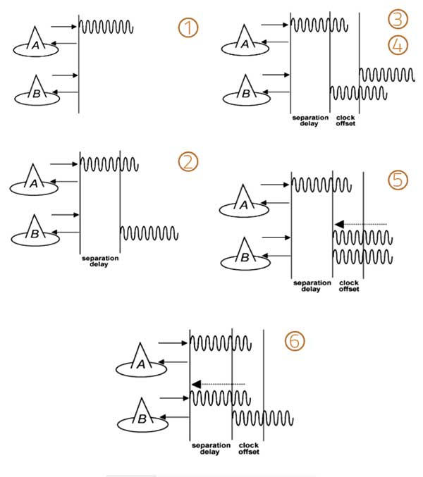
The TimeLoc procedure is described in the following steps for synchronizing two LocataLites (see Figure 1).
LocataLite A transmits a unique signal (code and carrier).
The receiver section of LocataLite B acquires, tracks and measures the signal generated by LocataLite A.
LocataLite B generates its own unique signal (code and carrier) which is transmitted, but, importantly, it is also received by the receiver section of LocataLite B.
LocataLite B calculates the difference between the signal received from LocataLite A and its own locally generated and received unique signal. Ignoring propagation errors, the differences between the two signals are due to the clock difference between the two devices and the geometric separation between them.
LocataLite B adjusts its local oscillator to bring the differences between its own signal and LocataLite A to zero. The signal differences are continually monitored and adjusted so that they remain zero. In other words, the local oscillator of B follows precisely that of A.
The final stage is to correct for the geometrical offset (range) between LocataLite A and B, using the known coordinates of the LocataLites. When this step is accomplished, TimeLoc has been achieved.
Figure 1. The TimeLoc process. (Image: Author)
The only requirement for establishing a LocataNet using TimeLoc is that LocataLites must receive signals from one other LocataLite. However, received signals do not have to come from the same central or Master LocataLite, because this may not be possible in difficult environments or when propagating the LocataNet over large areas. Instead, a LocataNet can “cascade” TimeLoc through intermediate LocataLites. For example, if a third LocataLite C can only receive the signals from B and not Master LocataLite A, it can use B’s signals for time synchronization instead of A’s, provided that B has already TimeLoc’d to the network. Therefore, by using “cascaded TimeLoc,” there is theoretically no limit to the number of LocataLites that can be synchronized.
Test item description
The NGBPS at White Sands consists of an operational LocataNet, where each node (a site instrumented with a LocataLite) is synchronized via Locata’s patented TimeLoc technique. The LocataNet, combined with a mobile Rover, is a subsystem of the 746 TS Ultra-High-Accuracy Reference System (UHARS), which provides PNT information in GPS-denied environments. The NGBPS operates in the 2.4-GHz industrial, scientific and medical band, which is far enough away from GPS frequencies to be unaffected by GPS jamming. Although it is currently used as a source of position truth during GPS jamming, the 746 TS understands that the NGBPS is potentially a source of high-accuracy timing data as well.
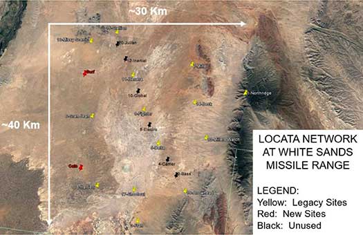
The UHARS is in the northern portion of White Sands Missile Range. It typically consists of 16 LocataLite sites. The master site is at North Oscura Peak, or NOP (labeled Northridge in Figure 2); all other sites are time synchronized to that master site.
Figure 2. Locata network at White Sands Missile Range. (Image: Author)
Each LocataLite site consists of:
one LocaLite
two monuments—pillars for antenna placement (Note: The two new sites lack the permanent monuments for antenna placement)
two transmit antennas
one receive antenna
one meteorological station—for meteorological data
one communication antenna
one trailer for power and transport
The communications antenna at each site is attached to a UHF modem that is used for 746 TS remote control of the LocataNet. This allows remote data logging, reconfiguration or monitoring of the network without having to drive to each site. However, it should be noted that no communications system whatsoever is required for the Locata NGBPS TimeLoc capability to run.
To support the timing tests, the LocataNet was reconfigured several times to meet requirements of specific test objectives. These configurations are described below.
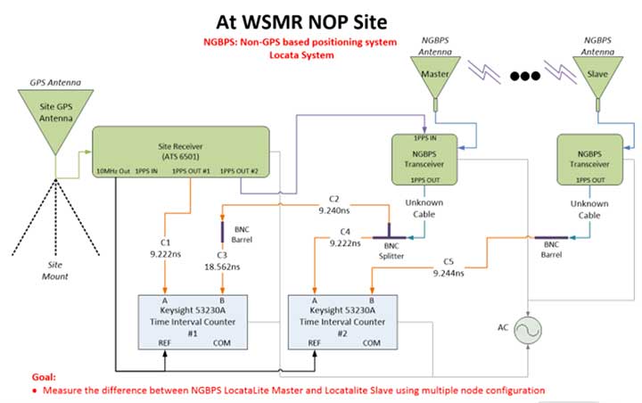
Static ground tests
Static ground tests involved multiple configurations. The first (Figure 3) consisted of two LocataLites (master and terminal slave) collocated at NOP close enough that their respective PPS outputs could be compared in a single time interval counter. A terminal Slave LocataLite was installed at NOP specifically for this test.
Figure 3. LocataLite Configuration 1: North Oscura Peak (NOP) site test instrumentation. (Image: Author)
This setup also facilitated simple network reconfiguration to change the number of LocataLite sites being tested. By programming LocataLites to TimeLoc to specific sites at White Sands and redirecting their respective antennas accordingly, the TimeLoc chain under test could be expanded to have multiple sites between the LocataLite master and the collocated terminal slave without changing measuring equipment instrumentation at NOP. This means that the time transfer could hop, or cascade, between one or more sites and be measured with the same test instrumentation.
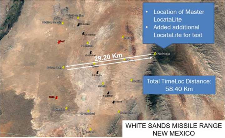
Configuration 2 consisted of three LocataLites: The master at NOP, a slave at Gran-Jean and the terminal slave at NOP. Again, the master and terminal slave were collocated close enough to each other that their respective PPS outputs could be compared in a single time interval counter, but this time the network was configured to cascade the TimeLoc signal through the slave at Gran-Jean, 29.20 km away. Since the TimeLoc signal now had to cascade through two sites and travel from the master at NOP to Gran-Jean and back to the terminal slave at NOP, the effective TimeLoc travel distance was 58.40 km (Figure 4).
Figure 4. LocataLite Configuration 2: Total TimeLoc distance is 58.40 km. (Image: Author)
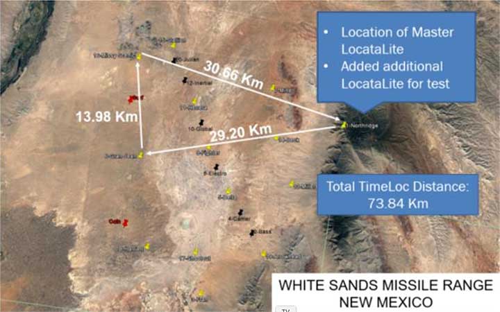
Configuration 3 consisted of four LocataLites: The master at NOP, a slave at Gran-Jean, a slave at Missy-Scenic and the terminal slave at NOP. This configuration forced the TimeLoc signal to cascade through three sites and travel a total distance of 73.84 km (Figure 5).
Figure 5. LocataLite Configuration 3: Total TimeLoc distance is 73.84 km. (Image: Author)
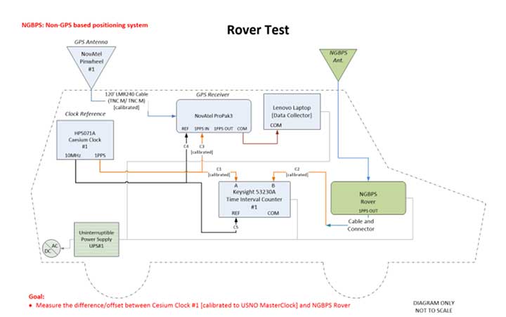
Ground vehicle test
For Configuration 4, a Locata Rover was instrumented on the squadron’s Small Test Vehicle (STV), which drove all accessible roads within the LocataNet’s coverage (Figure 6). During this mobile test, the LocataNet was configured with 10 active LocataLites. The Locata Rover in the vehicle used Locata signals from available nodes to calculate Locata network time, which was synchronized to the GPS timing receiver at NOP. The data collected determined how well network time is synchronized while in a moving vehicle.
Figure 6. Rover test installation on Small Test Vehicle. (Image: Author)
Test results
To collect the required data, USNO first had to characterize the performance of the master site’s GPS timing receiver at NOP, and then synchronize it to two separate USNO atomic clocks that could be used as remote timing references for the tests. The GPS timing receiver is equipped with a rubidium oscillator, which produces a GPS-disciplined 1 pps output signal. Its internal rubidium clock is a stable source of time with an advertised UTC (USNO) offset of a best case 15-ns root mean square (RMS) and a worst case 100-ns RMS.
The cesium clocks output 5- or 10-MHz sinusoids and a 1 pps signal. The cesium clocks output 5- or 10-MHz sinusoids and a 1 pps signal and were characterized relative to the USNO correction receiver, which USNO personnel had characterized relative to UTC. Correction data available from a time interval counter could then be applied to tie the timing receiver back to USNO time. The measurements at NOP recorded the difference between the timing receiver and the cesium clocks. Using the relationship between the cesium clocks and UTC (USNO), one could characterize the timing receiver’s time relative to USNO time.
The USNO calibrated measurements at the nanosecond level using two methodologies. The most common approach was simply to compare two 1 pps signals, a method known as “tick-tick.” Another important methodology is referred to as a “tick-phase,” which is a measurement of a sinusoidal signal compared to a 1 pps reference. Some timing equipment will have discrete time jumps with certain tick-phase measurements, because of how narrow the distance between the rising edges of a sine wave is compared to a 1 pps signal.
There’s a chance that the 1 pps signal is close to two rising edges of a sine wave, causing the signal to jump back and forth in its timing measurement, depending on which rising edge of the sine wave it uses.
Measurements were further complicated by the delicate nature of cesium clocks, which perform best under finely controlled laboratory conditions. Each cesium reference exhibits its own characteristics that must be observed, measured, and accounted for. Moreover, transporting them to White Sands Missile Range for this test where temperature fluctuations, moving vehicle vibrations, and altitude variations among devices were introduced made synchronization of these clocks particularly challenging. For example, USNO discovered that the Cesium Clock #1 had its internal batteries disconnected — possibly through the original shipment to White Sands, the constant vehicle vibrations while driving on the range, a faulty wiring in the battery terminals, or possibly a combination of all. This problem induced a random offset in the clock, and calibration had to be re-accomplished to reestablish traceability back to UTC (USNO).
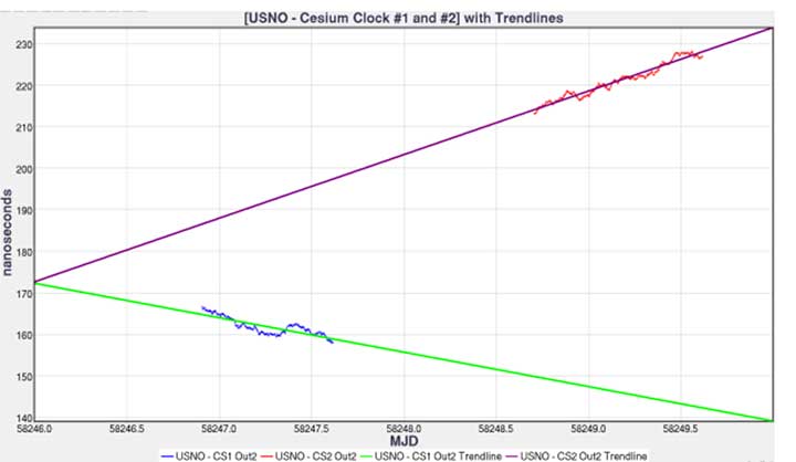
Figure 7 shows each cesium clock’s measured drift rate in nanoseconds/second and its corresponding linear fit. This trendline can then be used to project cesium clock #2 to the past and compare it to the measurements of cesium clock #1.
Figure 7. USNO cesium clocks with trendlines. (Image: Author)
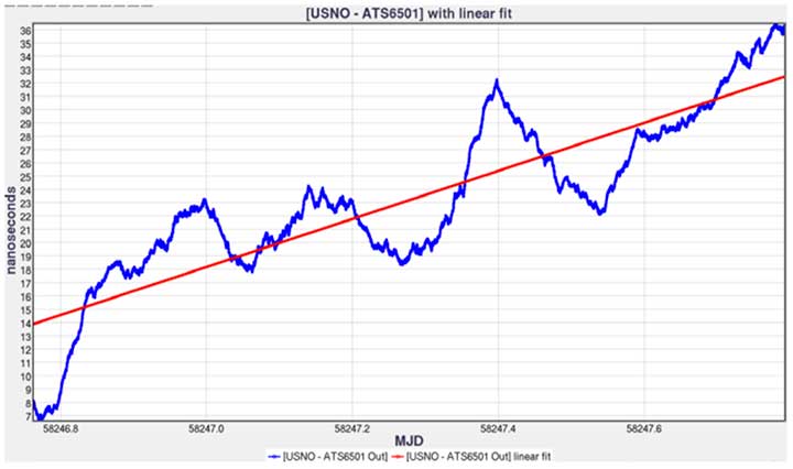
Figure 8 shows the relationship between the timing receiver and USNO master clock and its linear fit. Performing linear fit approximations of the cesium clocks likely introduced unknown errors, potentially increasing the variance of the 1 pps differences.
Figure 8. USNO versus timing receiver with linear fit. (Image: Author)
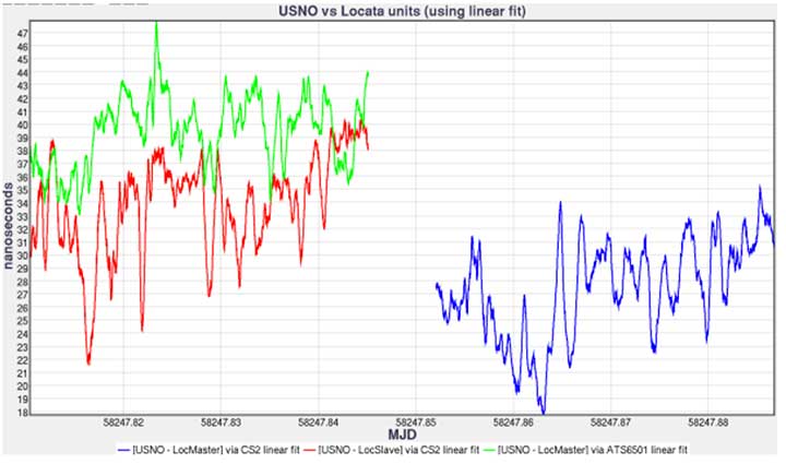
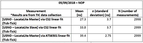
Comparing the 1 pps outputs of the LocataLite master and collocated LocataLite slave to the master site reference clocks (CS2 or timing receiver 1 pps out), the data is traceable back to USNO using the linear fits found for both the USNO timing receiver and cesium clock #2 (Figure 9).
Figure 9. USNO compared to Locata system for May 9, 2018, time interval counter measurements. (Image: Author)
LocataLite timing measurement bias was within 40 ns, and the stability was within 3.7 ns of the reference clocks (see Table 1). The stability of the system is encouraging, as the mean offset can be driven down by more precise measurements and more precise calibrations such as using a two-way satellite time-transfer calibration method (TWSTT).
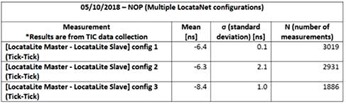
Table 1. USNO compared to Locata system tabulated values and statistics. (Image: Author)
In Table 2, we compare measured data of the 1 pps outputs of the LocataLite master to the collocated LocataLite slave and compute the Locata network internal synchronization in each of the network configurations tested. The data reveals that the network synchronization accuracy is ≤ 2.1 ns. Unfortunately, during Configuration 2 testing, which propagated the TimeLoc signal from NOP to Gran-Jean and back (a total distance of 58.40 km), a technician inadvertently obstructed line-of-site between Locata antennas and consequently temporarily disturbed TimeLoc. Those data points were not removed before this analysis, which is why the reported standard deviation in that configuration, although quite good at 2.1 ns, is nevertheless uncharacteristically high.
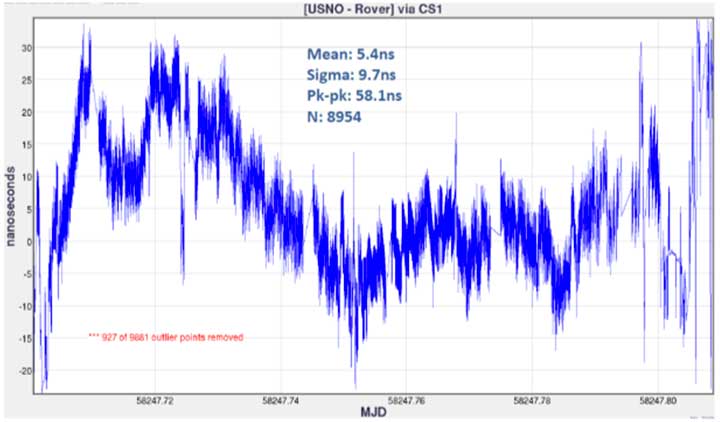
Finally, Figure 10 shows the timing measurements between the USNO master clock and the mobile Locata Rover, via the cesium clock #1 linear fit. Unlike in the LocataLite tests, the Rover is not TimeLoc’d to the network. Instead, it simply calculates its time from LocataLite signals within its line of sight, similar to how a GPS device will calculate its time from satellite signals. During this test, the Rover’s calculated timing accuracy showed a mean of 5.4 ns and stability within 9.7 ns of the USNO master clock, while driving all over the northern portion of the range. To produce the plot, 927 outliers were removed (3 sigma). The outliers occurred at the beginning and ending of the test, when the vehicle was moving from its parking location at Stallion Range Center (outside the operational LocataNet) to the test route and back. The buildings in the area obstructed line of sight and induced significant multipath, which degraded the Rover’s calculations.
Figure 10. USNO LocataLite Rover via CS1 linear fit. (Image: Author)
Conclusion
This endeavor for USNO to characterize the 746 TS NGBPS was met with many challenges, which emphasize the real-world difficulty of measuring time at these extremely fine levels in the field using atomic clocks. The USNO found that some non-linearity started occurring in the USNO – Cesium Clock #2 measurements because of the container of Cesium Clock #2 not being ideal for temperature stability. They also discovered that Cesium Clock #1 had its internal batteries disconnected due to an unknown cause. However, because of deliberate measurements between Cesium Clock #1 and Cesium Clock #2, the USNO was still able to provide calibration measurements but with degradation in the measurement clarity.
From the data collected, USNO personnel found:
The GPS timing receiver at NOP produced 1 pps timing accuracy consistent with its 15-ns RMS specification. Therefore, the reference time delivered to the Master LocataLite was synchronized to UTC within 15 ns.
A standard deviation measurement from Master LocataLite to UTC of under 4 ns.
Locata’s master-to-slave internal time synchronization (independent of GPS) was measured to be between 100 ps and 2.1 ns in 3 different Locata network configurations spanning distances up to 73.84 km (45.88 miles).
The timing measurements in the mobile Rover test show its ability to provide accurate time with a standard deviation of around 10 ns.
Many lessons learned throughout this experiment could be implemented to get more accurate measurements, especially when looking at the accuracies of the GPS time transfer throughout the NGBPS. Looking ahead, more accurate calibration values for both the GPS timing receiver and the Master LocataLite could be made by using a TWSTT method. This would simplify the number of measurements and provide a 1 pps signal of USNO’s master clock, resulting in up to 1 ns of accuracy in the reference time delivered to the Master LocataLite. Depending on the requirements of customers needing NGBPS time at White Sands, the 746 TS and USNO can potentially recharacterize the NGBPS timing accuracy and stability using this methodology.
Manufacturers
The LocataLites and Rovers that create much of the 746 TS NGBPS are manufactured by Locata Corp. The NGBPS synchronized to GPS time via a Microsemi ATS6501 timing receiver. The cesium clocks were Hewlett-Packard 5071A cesium primary frequency standard devices. The USNO used a Novatel ProPak3 for correction data, measured using a Keysight 53230A time interval counter.
Christopher Black earned a B.S. and M.S. in electrical and computer engineering from New Mexico State University. In November 2017 he joined the 746th Test Squadron, Holloman Air Force Base, as a navigation warfare analyst. Now, as lead reference engineer, he heads up research, development and maintenance of the squadron’s reference systems, including UHARS.
This article has been approved by the USAF for public release, #AEDC2019-205.
DroneShield has released a vehicle-mounted drone detection and defeat product, DroneSentry-X.
Lightweight at about 10 kilograms, it can be easily mounted on most vehicles. DroneShield expects the product to be of interest to military, law enforcement, security and VIP the markets. The product is suitable for both vehicle/convoy and fixed site installations. The product was developed in response to substantial customer interest, according to the company.
“Vehicle market for counterdrone protection is rapidly rising,” said DroneShield’s CEO Oleg Vornik. “In addition to catering for that segment, DroneSentry-X provides a more affordable detect-and-defeat solution for price-sensitive customers as an alternative to purchasing full-functionality DroneSentry product from us. DroneShield offers a complete suite of detection and defeat solutions to our customers, and this new product covers the customer need which we identified in our recent engagements.”
Undersecretary of Defense Michael Griffin. (Photo: DOD)
Augmenting GPS with other systems was suggested as the most promising area of improvement in a recently released memo establishing a Defense Science Board task force on positioning, navigation and timing (PNT).
On Dec. 16, the Department of Defense released a memo from Undersecretary Michael Griffin to the chair of the Defense Science Board. In it he outlined terms of reference for a year-long study of defense “position, navigation and timing control.”
Setting the stage for the effort, Griffin, who serves as undersecretary for research and engineering, outlined some challenges of relying too heavily on GPS. “The current system has less susceptibility to jamming and spoofing, but challenges remain — slow fielding of user M-code capability, cyber and kinetic threats. Degradation can occur in canyons, cities, and high signal multipath environments.”
He also seemed to indicate that, while further improvements to GPS were possible, they would likely yield only marginal returns and be very expensive.
“While performance and resilience continue to improve, the system has matured to the point that these changes have resulted in incremental improvement to overall system performance,” Griffin said. “The cost of the system and ongoing upgrades have experienced significant growth, making it hard to increase the density of the satellites to address the more challenging environments.
The memo suggests that, rather than focusing entirely on continual improvements to GPS, adding other systems to a PNT architecture for users will likely be more effective and economical.
One such addition may well be leveraging thousands of planned commercial communications satellites to also provide PNT.
“A future multi-mission constellation that can transmit and receive RF signal[s] across a broad spectrum will allow both the ability [to] provide and deny communication and PNT globally and will provide support to all essential warfighting missions,” Griffin said.
This idea is already being explored by Army Futures Command in partnership with the University of Texas at Austin’s Radionavigation Laboratory.
Yet Griffin cautions that using commercial communications satellites may or may not be a good idea. The memo asks the group to evaluate the benefits and risks of the military depending upon commercial systems.
Reinforcing the theme of focusing on architecture, Griffin’s final question to the study group deals with “the performance and resilience benefits” of adopting other PNT sources such as portable atomic clocks, visual sensors, and terrestrial-based navigation and timing.
This parallels the recently released DoD PNT Strategy, which calls for a wide diversity of PNT sources to create an architecture for greatly increased resilience and mission assurance. It envisions a multi-layered architecture of PNT sources with GPS providing a global layer, wide-area terrestrial systems like DARPA’s STOIC or eLoran for the regional layer, and short-range systems, interials, sensors and clocks providing the local layer.
The task force’s efforts are to conclude no later than February 2021, with a report by August of that same year.
A copy of Undersecretary Griffin’s memorandum is available here.
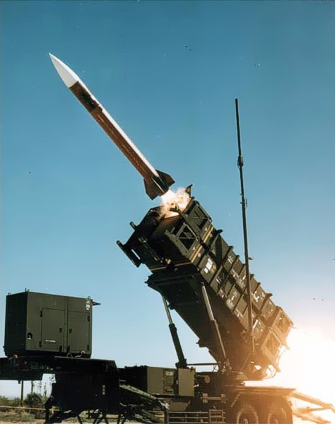
U.S. forces and air-defense missile batteries across the Middle East were placed on high alert Jan. 7 in preparation for possible Iranian drone attacks, reports CNN, including all Patriot batteries and forces in the area.
U.S. officials told CNN that intelligence mounted about a threat of an imminent attack against U.S. targets in the wake of the U.S. drone strike that killed Iranian general Qasem Soleimani. U.S. intelligence also observed Iran moving military equipment, including drones and ballistic missiles, over the last several days.
The movement may be an Iranian effort to secure its weapons from a potential U.S. strike, or put them in positions to launch their own attacks.
Iran has put missiles on its drones that have been used in other attacks, including a significant attack on Saudi oil installations last year (see below).
Targets of concern are U.S. locations in Iraq, Kuwait, Saudi Arabia, the United Arab Emirates and Jordan.
2019 Drone Tensions
Drones forces from both sides targeted assets in 2019. In June, Iran shot down a U.S. military drone that it claimed was an intruding American spy drone entering its territory. The U.S. said the drone was shot down in international airspace over the Strait of Hormuz.
In July, U.S. Marines jammed and destroyed an Iranian drone in the Strait of Hormuz from aboard the USS Boxer, an amphibious assault ship, because the drone has closed too close, to approximately 1,000 yards. Iran denied losing any of its drones.
In September, Iran was blamed for an attack on the Saudi oil industry, with drones and cruise missiles assumed launched from an Iranian base in Iran close to the border with Iraq. The Abqaiq oil plant was struck by more than a dozen projectiles.
Maritime Alert
On Monday, the U.S. Maritime Administration issued an alert to commercial vessels operating in the Middle East, citing multiple maritime threats and stating “there remains the possibility of Iranian action against U.S. maritime interests in the region.”
According to the alert, “The U.S. government is continually assessing the maritime security situation in the region to safeguard freedom of navigation, ensure the free flow of commerce, and protect U.S. vessels, personnel, and interests.
“U.S. Fifth Fleet Naval Cooperation and Guidance for Shipping (NCAGS) has the latest information on the dynamic maritime security threats and operational environment in this region. U.S. commercial vessels are advised to exercise caution and coordinate vessel voyage planning for transits of the Persian Gulf, Strait of Hormuz, Gulf of Oman, North Arabian Sea, Gulf of Aden, and Red Sea with NCAGS and follow NCAGS’s recommendations and guidance whenever possible.”
In 2019, military forces witnessed the global threat of GPS/GNSS interference grow, with more sophisticated threats and increasing military demand for assured operations in Navigation Warfare (NAVWAR) and GPS-denied environments.
Enemy forces are deploying more advanced jamming and spoofing technologies worldwide, jeopardizing the security and reliability of positioning, navigation and timing (PNT) data that feeds into GPS receivers, downstream networks and subsystems.
Military forces must vigilantly protect their information advantage from malicious attacks by delivering situational awareness, mission planning and warfighter solutions.
For these priorities, proven and efficient signal integrity solutions will be even more critical in 2020.
Requirements to Ensure Signal Integrity in 2020
Any critical system that relies on PNT data should go into the field with two known states:
First, it should withstand a GPS outage during testing and simulation — including rigorous jamming and spoofing simulation to predict how the system will react under various conditions. Simulation scenarios can vary in complexity, and newer software-defined simulators provide flexibility to meet current requirements while future-proofing investments in test equipment.
Second, the system should have a signal threat detection and alert mechanism. Critical systems also need backup layers such as anti-jam antennas, threat mitigation technology and alternative encrypted signals to ensure continuous operations, even in compromised environments.
Going into 2020, GNSS simulation and interference detection and mitigation (IDM) will continue to adapt to emerging threats and provide the essential foundation for Assured PNT.
For more about Resilient PNT and NAVWAR solutions, visit www.Orolia.com.
GPS signals are by far the single most widely used and most accurate source of navigation, positioning and timing (PNT), and this capability is deeply integrated into every aspect of our society. In particular, the timing service provided by GPS, while virtually unknown to the general public, is essential for a variety of digital operations — from performing financial transactions to operating cell phone networks to running the internet.
Of course, GPS — originally developed to guide nuclear submarines — is now vital to most military missions, and the system’s vulnerabilities are a source of great concern.
GPS has been remarkably reliable over the past quarter century. Solar flares are rare, multipath can be largely mitigated, and obstructed line-of-sight to the satellites is an acute problem only in certain environments, such as urban canyons.
The most serious intentional threats to GPS are spoofing and jamming. Jamming is more widespread — it is more easily accomplished intentionally and it also occurs unintentionally. In the defense sphere, intentional jamming is a regular occurrence. It is expected as a routine aspect of electronic warfare operations to disrupt and deceive, typically just before the shooting begins. Unintentional jamming includes recently re-emerging concern about potential interference by ultra-wideband devices.
Experts at NovAtel, Collins Aerospace, L3Harris Technologies and Honeywell address the challenges posed by jamming and the relative effectiveness of various anti-jamming approaches.
NovAtel
Tackling Jamming on Multiple Levels
Disruption by jamming of GPS’s PNT data “is occurring with a growing regularity,” said Dean Kemp, Defense Segment manager at NovAtel, part of Hexagon’s Positioning Intelligence division. The problem will only increase, given our reliance on GNSS and increasing demand for precision. In the military sphere, electronic warfare in Syria, as well as jamming in Ukraine, Korea, and Finland, “have shown that modern, high-power equipment is routinely being used to disrupt the military.”
In the civilian sphere, interference is a growing issue because of cheap and effective jammers available via the internet. People use these so-called personal privacy devices to defeat vehicle tracking devices for purposes ranging from avoiding supervision all the way to hijacking vehicles.
GNSS signals are vulnerable because the received power is so small that receivers can be disabled with an incident power in the picowatt (10-12 W) range. “Jammers come in many different forms,” Kemp said, “from low-power civil devices to complex and powerful military-grade electronic warfare systems that can disable civilian receivers from a few hundred meters to hundreds of kilometers.”
Situational Awareness. Users can fail to recognize that their GPS is being jammed, Kemp said. Beyond defending against possible jamming scenarios, it is also necessary to “identify, find, and characterize the source of interference and to provide this information to the user so that it can be used appropriately.” In the defense field, this is known as situational awareness.
Emerging jamming threats, Kemp explained, can be understood within the context of cyber and information warfare using the Cyber Electromagnetic Activities (CEMA) layered approach. It recognizes a cognitive layer — a human decision based on PNT data; a virtual layer, in which PNT data are used to inform or support networked systems; and a physical layer, the hardware used to provide and protect PNT data.
Therefore, effective anti-jamming requires that:
users understand the system’s vulnerabilities and identify when they are being jammed, so that they can resort to traditional means for positioning and navigation (but not timing)
PNT data be protected and verified before being trusted
on the physical level, there be a multi-layered and heterogeneous approach that provides assured PNT information in the presence of jamming and spoofing without quantifiable loss of accuracy.
By combining these considerations at each layer, “they form a unified view on capability,” Kemp said.
Spoofing with Pokémon. Jamming threats are evolving, employed by both civilian and state actors. Worse, these threats are augmented by spoofing. While spoofing is harder to achieve than jamming, it is potentially more concerning. “Spoofing the receiver by rebroadcasting the GNSS signals or by generating them from a simulator has become a regular occurrence,” Kemp said.
Spoofing came to public attention in 2016 when enterprising programmers designed location-deception apps to hack the Pokémon Go mobile game. Instances have since been reported worldwide. Because early spoofing demonstrations were conducted against simple GPS L1 C/A-code receivers, it was initially hoped that spoofing could be defeated by using dual- or multi-frequency receivers.
However, it has been demonstrated that multi-frequency receivers using commercially available components can also be spoofed, “at least when the receiver is using multiple frequencies of GPS,” Kemp noted. “Adding further GNSS signals will help, but the best defensive measure is to employ, if authorized, an encrypted military signal.”
Coverage Improvement Factor. Typically, the effectiveness of an anti-jam system is assessed on the basis of the jamming to signal ratio (J/S) figure in decibels, which depends on variables such as the receiver’s front-end RF bandwidth, the signal type being tracked (C/A versus P(Y) code), the signal tracking threshold of the receiver, the receiver platform dynamics, the choice of receiver oscillator, the interference type and antenna characteristics.
Difference in how manufacturers calculate J/S led to the invention of the coverage improvement factor (CIF), adopted by the GPS Joint Project Office. “CIF gives a single number that describes the effectiveness of an anti-jam system for a particular jammer scenario, given that space vehicle positions vary by elevation and azimuth,” Kemp said.
However, the use of CIF to assess the anti-jam performance is a highly technical process and the results are usually classified. He discussed current approaches to anti-jamming.
Multi-element, controlled reception pattern antennas (CRPA), which pass the good signal to the receiver while nulling out the interference, are the first line of defense. “The system can dynamically change the gain pattern of the antenna so that as the platform and jammers move, the gain pattern adapts so that nulling continues effectively.”
The use of multiple constellations and frequencies can be an effective tactic to mitigate interference, “but relies on the jammer not covering the bands of interest.”
“Obtaining actionable data on interference is almost as important as mitigation,” because it enables users to modify plans. However, “interference effects can be difficult to diagnose and complicated to track down.”
Monitoring automatic gain control can indicate jamming.
“Coupling a GNSS receiver with a robust inertial measurement unit (IMU) will provide a higher level of protection for GNSS signals due to the IMU providing reliable position, velocity and attitude even through short periods when satellite signals are blocked or unavailable.” However, IMUs are liable to drift, resulting in degraded performance.
There are many approaches to designing anti-jam systems. They must be balanced against user requirements, which vary significantly. “A layered approach is the best form of defense against jamming and spoofing,” Kemp said, starting with protecting the incoming GPS signal. “One of the highest levels of protection is from an anti-jam antenna system paired with a GNSS receiver that is tightly coupled with an IMU.”
Finally, given that jamming attacks are now to be expected on the battlefield, it is critical to train users on the best response.
Collins Aerospace
Artist’s concept: Collins Aerospace
A Potent Triumvirate of Tools
While sources of deliberate jamming are on the rise, the vast adoption of GPS means that “even the non-deliberate sources of jamming will have an asymmetric impact on end users,” said Sai Kalyanaraman, Ph.D. and Technical Fellow at Collins Aerospace. Challenges posed by jamming depend on the receiver, mission and performance needs, while the source of unintentional jamming could be “something as simple as a TV antenna that is transmitting harmonics into the GNSS band.”
Kalyanaraman outlined viable approaches to interference mitigation and anti-jamming:
Integration with inertial navigation systems (INS) can provide the platform’s attitude, which is required for beam forming. This, in turn, is required for some of the CRPA GNSS Anti-jam signal processing modes. It can also alert the user of jamming when the INS position diverges dramatically from that provided by the GPS receiver.
Use of multiple frequencies is a form of robust design against interference.
For authorized users, M-code will provide additional limited capabilities against jammers.
Integration of GNSS with other PNT sensors to help address GNSS-denied environments.
GNSS signals have the advantage that the true signal is well under the noise floor; therefore, “as long as you can characterize the noise floor adequately from the receiver design/installation perspective, anything that shows up above the noise floor typically does not belong in that slice of the spectrum,” Kalyanaraman said. Combining a CRPA, a platform orientation sensor (like an INS), and a GPS/GNSS receiver, “you have a fairly potent triumvirate of tools that you can use to help mitigate the impacts of jamming and potentially spoofing.”
Collins produces multiple variants of its digital integrated GPS anti-jam receivers (DIGAR). “Depending on which variety you choose, you can essentially have a receive apparatus that can perform basic nulling all the way up to beam-forming and direction finding and help provide resiliency against high jamming signal levels and other threats that emulate a GNSS-like signal in space,” Kalyanaraman said.
L3Harris
L3Harris develops gun-hardened anti-jam solutions for the M1156 Precision Guidance Kit Modernization program. The kit turns 155-mm artillery shells into smart weapons. Here, soldiers test the kit for accuracy. (Credit: U.S. Army/Spc. Robert Porter)
Field Tests Verify PNT Reliability
Dealing with deliberate and unintentional interference with GPS requires agreeing on the level of enhancements required, reducing the time and cost needed to integrate them into systems of systems, and “centralizing PNT generation and distribution functions on a platform to reduce user equipment redundancies and increase the leverage of future PNT enhancements,” said Dave Duggan, president of the Precision Engagement Sector at L3Harris Technologies.
The increase in interference “creates a cascading negative effect to PNT client mission systems,” Duggan said, including the systems of systems for sensing, maneuver and fires [military-speak for the use of weapon systems].” The capability of anti-jam countermeasures “scales across a range of performance, size, weight, power and cost points and can be tailored to a given threat space, improving the performance of even legacy user equipment.”
Spoofing, which inhibits receivers from forming a solution or, worse, tricks them into passing misleading PNT solutions to other systems, is a bigger challenge than jamming because it can result in aborted missions and loss of life and usually requires new receivers, Duggan said.
Duggan defines a reliable anti-jam/anti-spoof capability as one that “provides a PNT solution with a high level of confidence in its accuracy, authenticity and integrity for their applications and anticipated threat environments — all at a reasonable cost/performance point.” Confidence in the solution requires “extensive analysis, threat modeling, simulation and testing of the anti-jam/anti-spoof capability.” For this reason, “L3Harris has worked extensively in developing simulation and testing environments of the highest fidelity and continues to participate in numerous live field test events to establish that foundation.”
L3Harris develops and produces digital anti-jam antenna electronics for U.S. and allied end use.
Honeywell
Honewell’s HGuide micro-electro-mechanical system (MEMS) inertial measurement units (IMUs) and INS are designed to be integrated with GNSS receivers. (Photo: Honeywell)
Integrating GNSS with Inertial
Heightened awareness of intentional and inadvertent jamming threats has less to do with new types of threats and more to do with the increased importance of precise PNT coupled with more frequent instances of jamming, according to Chris Lund, senior director, HGuide Navigation and Sensors at Honeywell Aerospace.
“As applications become more reliant on highly accurate and reliable position and timing information provided by navigation systems, the consequences associated with the data not being available or not being correct quickly escalate,” Lund said.
The best way to measure the impact of a jamming threat and the capabilities of countermeasures is “to determine in actual real-world use cases whether the desired application outcome can still successfully be achieved,” Lund said.
The most promising approach to anti-jamming is integration of GNSS receivers with inertial navigation systems (INS) and other PNT systems. “Given the complementary aspects of many of the available approaches in the anti-jamming toolkit, it’s often best to leverage however many tools are available and needed to allow the application to achieve its desired outcome,” Lund said.
By Tony Murfin GPS World Professional OEM Contributing Editor
In today’s world where local conflicts can spill over into many other places, it’s become common to encounter GPS signal jamming. Even in locations that defense forces might have considered “backwater” in terms of technology, enemies can apparently launch attack drones, jam adjacent countries, and generally render GPS, if not GNSS, useless for navigation.
The U.S. military came up with anti-jam technology to counter foreseen jamming scenarios several decades ago, but the initial seven-element controlled radiation pattern antenna (CRPA) designs were bulky and required multiple RF antenna cable connections to large, remote receiver processor units. These units not only processed the signals to derive position, but also eliminated jammer and satellite signals in the direction from which the jamming signal was received (null processing). Most of these early units were large and power hungry, so their application was limited to larger aircraft and ships.
Anti-jam technology has gradually evolved over time. Component integration and miniaturization has enabled CRPA performance to be self-contained within the antenna enclosure. At least one design has now migrated the null-processing into the same enclosure as the CRPA antenna, and is sold on a commercial basis to several military forces around the world. The device outputs a single composite RF signal that has been cleaned of any detected jamming signals for use by both commercial and military remote receivers alike.
Now Quantum Reversal (QR) — a new company based in Calgary, Alberta, Canada — has come up with a novel design that processes the CRPA signal in the RF domain, eliminating the need for extensive null-processing electronics. Without these signal-processing electronics, power requirements are reduced from about 15–30 watts to around 1 watt, the size is smaller (4 inches in diameter versus the nominal 6–8 inches in diameter), and cost is significantly lower. These reductions might allow this new anti-jam technology to move into small unmanned aerial vehicle (UAV) applications, timing networks, and reference monitoring networks where continuous uninterrupted GPS/GNSS service is mandatory.
This antenna is designed to enable continuous navigation using GPS or GNSS signals in the presence of unintentional low- to medium-power interference signals. It should be able to reduce the power of an unintentional interference or jamming signal by 35–45 dB, depending on whether it contains three or four CRPA antenna elements.
Increasing the number of antenna elements of the QR design improves the null depth (on average 8–10 dB per antenna element) at the expense of increased circuit complexity, power consumption and antenna size. An average null depth of –70 dB may be possible with a seven-element CRPA antenna. (Image: Quantum Reversal)
TDKC has proven capabilities in microelectronics trust and assurance, space domain awareness, and advanced visualization for enhanced situational awareness. PreTalen’s core competencies are the related practices of cyber warfare, navigational warfare, and positioning, navigation and timing (PNT) techniques and technologies in support of defense and offensive operations to counter adversaries.
Both companies are headquartered in Dayton, Ohio.
The acquisitions more than double the number of Centauri employees in the region to more than 300, supporting customers across the space, cyber and intelligence markets.
In addition, to bringing TDKC and PreTalen’s capabilities to bear for Centauri’s broader customer base, Centauri is building additional research and development labs, and secure facilities in the Dayton region to expand innovation and cutting-edge solutions for Centauri’s customers.
“Both TDKC and PreTalen have exceptional talent and share a common culture of innovation in pioneering new capabilities for the warfighter” said Dave Dzaran, CEO of Centauri. “With TDKC, we are building world-class capability to help ensure trusted microelectronics in the supply chains for the defense and intelligence communities. Their expertise in space domain awareness brings additional AI and machine learning technology to further strengthen Centauri’s existing space-related mission capabilities focused on the next generation of solutions that will serve this rapidly-evolving domain.”
“Similarly to TDKC, PreTalen’s unique skill sets relating to all aspects of the PNT architecture serve as a true differentiator on their programs,” said Dennis Kelly, president and COO of Centauri. “PreTalen has built a critical mass of the most innovative employees in both PNT and cyber, and we are excited to facilitate collaboration not only with our Dayton operations but also across the rest of our company.”
Greg Gerten, CEO of PreTalen, and Dan Schiavone and Eric Loomis, founders of TDKC, as well as both of their leadership teams, including Bruce Hart, will become a part of Centauri’s growing operations in the region.
This investment in the Dayton region comes on the heels of Centauri’s hiring of Col. Elena Oberg, former vice commander of the Air Force Research Laboratory, headquartered just outside Dayton at Wright-Patterson Air Force Base.
With the addition of TDKC and PreTalen, Centauri now has more than $475 million of annual revenues and 1,650 employees, approximately 20% of which support customers located in the Dayton market.
“I speak for all of PreTalen when I say that we are extremely excited to be joining forces with Centauri,” Gerten said. “Our team is eager to apply our core capabilities to the space and Intelligence communities, and we look forward to replicating our past success for an ever-increasing number of customers. Furthermore, Centauri’s focus on innovation meshes well with what we’ve spent 12 years building here at PreTalen, and I’m thrilled to continue our journey with their support.”