Microsemi Corporation’s new SyncServer S650 SAASM server incorporates a Selective Availability Anti-Spoofing Module (SAASM).
The SAASM capability provides a highly secure, accurate and flexible time and frequency platform for synchronizing mission-critical electronics systems and instrumentation applications in the defense market, such as satellite communications and defense operational infrastructure, the company said.
Military Grade. The new SyncServer S650 SAASM, designed for use by the U.S. Department of Defense (DOD) and other government agencies as well as their approved suppliers, received the GPS Directorate Security Approval to incorporate a military-grade, GPS SAASM receiver module.
Microsemi SyncServer S650 SAASM Time and Frequency Server.
This enables U.S. armed forces to confidently deploy features of Microsemi’s popular commercial SyncServer S650 in a military-grade configuration. In addition, the integrated SAASM module adheres to industry standards allowing for a migration path to GPS Military Code (M-code) support.
“Our key military and DOD-related customers require flexible, secure and extremely reliable time and frequency technology for their most critical applications, which they have come to rely upon from Microsemi. Enabling support for SAASM provides the extra security and reliability necessary for this market,” said Randy Brudzinski, vice president and business unit manager of the Frequency and Timing Division at Microsemi. “The addition of the SyncServer S650 SAASM to our product line further demonstrates Microsemi’s commitment to providing the highest quality time and frequency technology in support of vital government programs.”
The SyncServer S650 SAASM is a highly versatile time and frequency system with the company’s FlexPort technology for multiport, user-definable output signal configurations for time codes, pulses and a variety of signal types essential for system synchronization.
This makes the SyncServer S650 SAASM ideal for DoD electronics system engineers synchronizing mission-critical, system-level instruments. This is coupled with Microsemi’s NTP Reflector technology for robust security, accuracy and reliability of network-based time services such as Network Time Protocol (NTP) and Precision Time Protocol (PTP).
Resilience to Threats. According to a 2017 GNSS Market Report, global navigation satellite system (GNSS) jamming and spoofing are specifically identified as increasing and notable cybersecurity threats to critical infrastructure.
Furthermore, resilience to these threats has become mandatory by critical infrastructure policy makers and GNSS receiver manufacturers. Without the use of SAASM technology in the presence of these threats, deliberate or unintentional, the most mission-critical systems operated by the DOD may be subject to the side effects of degraded time and frequency performance.
Microsemi’s new SyncServer S650 SAASM is designed to generate precise time and frequency signals to synchronize high bandwidth mission-critical communications systems and critical infrastructure requiring the highest levels of security support.
In addition to offering superior low phase noise performance, the device is compliant with the Joint Chiefs of Staff SAASM GPS mandate and developed for authorized military users only.
Surrounding sounds may not be a common way of determining location. But on the battlefield, warfighters need to know the direction of gunshots to enable a proper response.
Weighing 12 ounces, the Boomerang Warrior-X by Raytheon BBN Technologies provides immediate hostile fire location awareness to individual soldiers and gives unit leaders shooter grid coordinates, according to the company. These situational awareness enhancements improve coordinated team responses to hostile fire.
Incoming shot announcements are transmitted to a built-in speaker or an earpiece while a lightweight display provides range and azimuth of the shooter position. As the soldier moves, the system compensates for the soldier’s motion and continually updates the threat’s location on a wrist display.
The Boomerang Warrior X system.
This summer, an undisclosed Gulf nation has awarded a direct commercial sales contract to Raytheon BBN Technologies valued at more than $10 million for the delivery of 2,000 Boomerang Warrior-X systems during the next 12 months.
“This technology is a proven life saver on the battlefield,” said Ed Campbell, president of Raytheon BBN Technologies. “Boomerang delivers the best performance of any available shooter detection system today at the lowest cost.”
Raytheon BBN Technologies is a wholly owned subsidiary of Raytheon Company.
The German Ministry of Defense selected Rockwell Collins’ NavHub navigation system to provide GNSS availability to a variety of its military vehicles.
The NavHub system serves as a next-generation GNSS- and Military-code (M-code)-enabled solution for the German Armed Forces.
Customizable for ground and maritime platforms, NavHub provides a variety of vehicle interfaces, meets the standards required by military vehicle operators, and allows users to receive data from multiple secure and open-service GNSS constellations to simultaneously confirm the navigational solution.
Access to multi-constellation GNSS and GPS M-Code will provide a significantly enhanced navigational solution over the current GPS-only solution.
Work under the contract will be performed in Rockwell Collins’ facilities in in Europe.
About the NavHub GNSS navigation system
NavHub (Image:: Rockwell Collins)
Based on Rockwell Collins Selective Availability/Anti-Spoofing Module (SAASM) GPS receivers, NavHub is strategically designed to meetfast-moving and demanding combat environments.
Through the use of dual-installed GNSS receivers, NavHub provides an assured navigational solution, interfaces and GNSS upgrade path to support modern operations platforms.
SAASM security (expansion to M-code), expansion to multi constellation GNSS
Extended platform interfaces, including Ethernet, USB and CAN
Extended performance in a jammed environment (i.e., 41 dB while tracking and 24 dB during initial acquisition)
“NavHub meets the critical mission need for accurate navigation support for fast-moving platforms and challenging environments,” said Claude Alber, vice president and managing director, Europe, Middle East and Africa for Rockwell Collins. “Our military GNSS receivers will provide significantly enhanced navigational capabilities to military vehicles and will mitigate terrain, forest and urban degradation as it will raise the number of satellites used from 28 to well over 100.”
By Christopher Ball, 412th Test Wing Public Affairs
What happens when GPS isn’t available?
A collection of U.S. Department of Defense units and universities found out when they gathered at Edwards Air Force Base, California, to evaluate various aerial platforms in a degraded GPS environment this summer.
The week-long test event called DT NAVFEST — short for Developmental Test Navigation Festival — was the first large-scale program of its kind, according to James Cook, KC-46A project manager with the 418th Flight Test Squadron.
“DT NAVFEST was established to provide a locally more realistic GPS jamming environment in which aircraft platforms and unmanned aerial vehicles could evaluate their performance under a degraded GPS signal,” Cook said. “Other locations around the U.S. provide such environments, but having it locally allowed for direct program input and cost savings to customers by not having to deal with the logistics costs of deploying to those locations.”
Cole Johnson, technical lead for NAVFEST, explained how they create a degraded GPS environment.
“GPS signals are super faint,” he said. “Imagine a 30-watt lightbulb 12,000 miles in space. So it doesn’t take much interference for your smartphone’s GPS to lose lock on such a low power signal. Interference could occur from walking in a dense forest, through a canyon, inside a building, driving among skyscrapers, or from GPS jammers. The end effects of GPS jammers aren’t much different than the other causes of interference, they all make it harder for your GPS receiver to pick out faint GPS signals from the air, except jammers do it by adding noise to the environment.”
Teams from the University of Illinois Champagne Urbana and Stanford University were invited to the first-ever DT NAVFEST at Edwards Air Force Base to test their projects in a GPS degraded environment. (Photo: U.S. Air Force/Wei Lee)
The GPS jammers and support came from the 746th Test Squadron at Holloman Air Force Base, New Mexico.
According to Wei Lee, test safety engineer with the 412th Test Wing, the universities were invited to participate in DT NAVFEST on a trial basis with the hope of expanding to other institutions in the future.
“Live GPS jamming data is extremely difficult for academic labs to obtain due to the complexity of working with the Federal Aviation Administration and regional first responders,” Lee said. “It is crucial that the Department of Defense support basic research and development that is ongoing in our nation’s top academic institutions. Many of the low technology readiness level projects will eventually migrate from academic labs to defense industry and military applications. Allowing the labs to participate on a non-interference basis is a win-win situation.”
To minimize the effect on the local community and air traffic, planning of the GPS jamming was initiated months in advance. According to Johnson, the GPS jammers had a vertical reach of upwards of 30,000 feet, so the first step was contacting the FAA, which provided a list of “green” times when commercial air traffic was at its lowest. This led to the testing being performed between 1 and 6 a.m. on test days.
Johnson said the team performed extensive modeling and simulation to identify how far the GPS interference would reach. “Not just at 30,000 feet, but ground level as well.”
The models suggested a small part of the Antelope Valley — a couple of small towns around Edwards — could be affected. “We wanted to err on the side of caution, so we constructed a huge list of emergency services from the Antelope Valley to contact.”
The team also set up phone lines the FAA and any emergency service could call up during testing and request the jammers to be turned off.
The 746th Test Squadron from Holloman Air Force Base, New Mexico, provided an array of GPS jamming equipment and support for DT NAVFEST at Edwards Air Force Base. The jammers provided a degraded GPS environment for testing multiple aerial platforms throughout the week. Testing was done from 1 to 6 a.m. each day to minimize impact on the community and civilian air traffic. (Photo: U.S. Air Force/Cole Johnson)
Cook said the event was extremely successful, judging by the feedback from the customers.
“For a first-of-its-kind event, it executed fairly smoothly, thanks to the test team and customers’ direct involvement,” he said. “The technical knowledge and support from the 746th TS was awesome. And the support given to this program from 412th Test Wing all the way down to the Airman on the ground providing direct support.”
The U.S. Air Force has awarded Lockheed Martin a $45.5 million contract to provide military code (M-code) early use (MCEU) capability to the Global Positioning System (GPS).
Part of the Air Force’s overall modernization plan for the GPS, M-code is an advanced, new signal designed to improve anti-jamming and protection from spoofing — as well as increased secure access — to military GPS signals for U.S. and allied armed forces.
MCEU will provide command and control of M-code capability to eight GPS IIR-M and 12 GPS IIF satellites on orbit, as well as future GPS III satellites, which the Air Force expects will begin launching in 2018.
MCEU is envisioned as a way to accelerate M-code’s deployment to support testing and fielding of modernized user equipment in support of the warfighter.
The Military Code (M-Code) Early Use (MCEU) contract will accelerate deployment of command and control of M-code capability to GPS IIR-M and GPS IIF satellites currently on orbit, as well as future GPS III satellites (like GPS III SV02 above). (Photo: Lockheed Martin)
The U.S. Air Force’s MCEU contract directs Lockheed Martin to upgrade the existing Architecture Evolution Plan (AEP) Operational Control System (OCS), allowing it to task, upload and monitor M-code within the GPS constellation. The contract includes new software and hardware development that will be deployed in 2019 to worldwide ground facilities that support the Air Force’s GPS.
“When people think of GPS, they often think of the satellites that provide the signals, but do not remember the important ground system behind it,” said Mark Stewart, Lockheed Martin’s vice president for Navigation Systems. “We recognize the ‘ground’ is critical for any major space mission constellation and we are proud that we can help the Air Force with this part of their GPS modernization plan.”
The AEP OCS — maintained by Lockheed Martin under the GPS Control Segment (GCS) Sustainment Contract — controls the 12 GPS IIR, 8 IIR-M and 12 IIF satellites in orbit today. The company has successfully implemented several recent projects to modernize and sustain the system for the Air Force.
In June, Lockheed Martin deployed the first of its state-of-the-art GPS Monitor Station Technology Improvement Capability (MSTIC) receivers at Cape Canaveral Air Force Station. The software-defined MSTIC system replaces 30-year-old hardware, positioning the Air Force to take advantage of commercial off-the-shelf technology enhancements in processing power, reliability and cybersecurity in the future. Six Air Force AEP OCS monitoring stations around the world will receive the MSTIC upgrade by the end of 2017.
In February 2016, the Air Force awarded Lockheed Martin the GPS III Contingency Operations (COps) contract to upgrade the AEP OCS with new capabilities so it could support the more powerful, next-generation GPS Block III satellites. The COps program passed a successful Critical Design Review milestone with the Air Force in December 2016.
Also in 2016, under the GCS contract, Lockheed Martin completed the commercial off-the-shelf upgrade No. 2 (CUP2) project — part of a multi-year plan to modernize the AEP OCS’ technology and enhance the system’s ability to protect data and infrastructure from internal and external cyber threats, as well as improve its overall sustainability and operability. CUP2 is now fully operational and managing the current GPS constellation.
Telephonics Corporation’s subsidiary, Systems Engineering Group (SEG), will demonstrate autonomous UAV control and PULSEbox this month during the Annual Naval Technology Exercise (ANTX), Dahlgren (Virginia) Division event.
ANTX-Dahlgren, being held Sept. 13-14, is a two-day event providing a low-risk environment to evaluate technological innovations at the research and development level before technologies become militarized and integrated at the operational level.
The autonomous UAV control demonstration will include a system manager in a UAV control ConOps scenario. System Manager is a model-based expert system of systems, which can plan, schedule and initiate ConOps processes to provide round the clock automation in the Flight Dynamics Operations Area (FDOA) on NASA’s Magnetospheric Multiscale (MMS) mission. This enables NASA to minimize human involvement in controlling satellite maneuvers along with optimizing data downloads.
PULSEbox offers a high fidelity, real-time, RF threat scene generator that integrates SEG’s threat models with optimized hardware. The system will create advanced test ecosystems by providing real-world target simulated threat states and related radar representations in laboratory settings, leading to improved testing of interoperable elements before live-sea testing events of air-breathing and ballistic missile threats, the company said.
“Both the autonomous UAV control and PULSEbox technologies align with the U.S. Navy’s requirements for more autonomous systems with limited human control requirements and more realistic training, simulation and modeling environments,” said Michael Anderson, Telephonics vice president and SEG general manager.
In the July and August issues of the magazine, the “Out in Front” editorials held forth on the perfection or lack thereof in the GPS signal and service.
Now it’s your turn!
Give us your opinion at gpsworld.com/17augustpolland we’ll publish the results in the September issue. And you’ll gain entry to a random drawing for a $50 gift card.
The question is: How close to perfect is GPS performance?
And your choices are:
Absolutely perfect. 100 percent.
Nearly perfect. The space segment functions flawlessly. The only problems are with jamming and user equipment.
Almost nearly perfect. There have been a few hiccups in space, then there’s jamming, and user equipment weaknesses.
Not nearly close enough to perfect — but pretty good. The (admittedly rare) operator miscue, jamming, spoofing, and other exploitable user equipment weaknesses.
Fair, but a long way to go. All the above cited problems, plus lack of signal reception under canopy, urban canyons, indoors.
Not a passing grade. But it’s the best I have, so I grit my teeth and use it.
Pretty poor if you ask me. It just does not meet my requirements.
Other (please specify)
For background and two different views on the controversy engendered by a U.S. Air Force public release on this subject, see:
In the battle for reliable positioning and timing, the U.S. Army is engaged in a multitude of activities, including mounted and dismounted A-PNT (assured position, navigation and timing) systems, anti-jam technology and pseudolites.
The idea is simple: Take some GPS satellites, and put them on or near the ground. Now you have a navigation system where you have full control over the locations and power of the transmissions. You can ensure that the transmissions reach places that GPS normally struggles with, such as deep urban canyons, forests and valleys.
You can turn up the transmit power, so they are much harder to jam than spaceborne GPS signals. These pseudo-satellites, commonly referred to as pseudolites, have seen steady interest over the years for a variety of applications.
Now the U.S. Army is pursuing the use of pseudolites as part of its initiative to maintain operation in GPS-denied environments.
Pseudolite Basics
There are various types, and use-cases, of pseudolites. In this column we’ll consider the direct-ranging pseudolite, which can be simply considered as a ground-based GPS satellite. If we deploy several pseudolites on the ground, we can imagine that a normal GPS receiver would be able to receive the GPS-standard transmissions and derive a position, just as we would from the space-based satellite transmissions.
The fact that the pseudolites are ground-based introduces us to the first consideration: The locations of the transmitters are no longer described by orbital parameters. Instead of calculating the position of satellites, we need to describe the location of the pseudolites in geographical terms, perhaps with a fixed position described in Earth-centered, Earth-fixed (ECEF) coordinates.
The transmitted navigation data message, which would normally contain almanac and ephemeris information, may now need to contain the geographical position of the pseudolite. Not a problem, but our GPS receivers will need a software upgrade to be able to handle this situation.
The deployment of the pseudolites themselves poses an interesting problem. Imagine a military scenario, where the army is deployed to a region of interest. Navigation warfare is taking place, and GPS is frequently jammed in the region.
High-power pseudolites are deployed to allow the army to navigate despite the jamming, using the same standard-issue GPS receivers that soldiers are familiar with.
The first problem is, having placed your pseudolites in position, how do you know where they are?
You might choose to place your pseudolites at locations that have previously been surveyed, so you know where they are in advance. But this isn’t likely, particularly if you’ve just moved your troops into an unfamiliar area. You might also want to move the pseudolites regularly, as the army moves to new ground. So the pseudolites need to determine their own position, and the easiest way for at pseudolite to determine its own position is with GPS, of course.
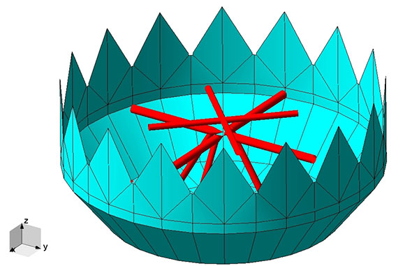
Isn’t this a bit incestuous? If we’re using pseudolites because GPS is jammed, how does the pseudolite get its position? This is why military pseudolites will typically be fitted with some form of anti-jam technology, such as a controlled radiation pattern antenna. This allows the pseudolite to receive GPS satellite signals in the presence of jamming, determine its own position, and transmit that as part of its own navigation message.
So, now that we can get pseudolite locations, the next consideration is: Where should pseudolites be placed?
A-DOP-ting a Good Layout
If you know about GNSS, you’ll be familiar with the concept of dilution of precision (DOP). This is essentially a measure of how accurate your position estimate is likely to be, due to the geometry of the satellites: a good wide spread of satellite positions gives us better accuracy.
Figure 1. Poor satellite geometry, resulting in high DOP. (Image: Michael Jones)Figure 2. Good satellite geometry, resulting in low DOP. (Image: Michael Jones)
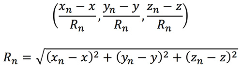
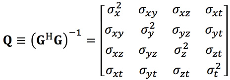
The DOP can be easily calculated by forming a covariance matrix of the geometry, expressed in an appropriate coordinate frame. If (xn, yn, zn) denotes the position of the nth pseudolite, and (x, y, z) the position of the receiver, we can express the unit vectors from the receiver location to the pseudolite location:
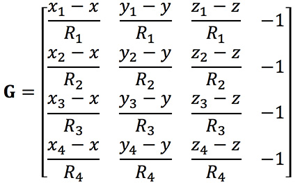
We then form a matrix of these unit vectors:
Finally, we form the covariance matrix from which we can extract the DOP values:
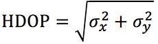
From the elements of this matrix we can determine the various DOP metrics. Let’s concentrate on horizontal DOP (HDOP), given by:
When positioning using GPS satellites, we are blessed with a Walker constellation that generally gives us a nice spread of satellite locations (unless we’re in an urban canyon). On the battlefield, using pseudolites, we do not have the same luxury.
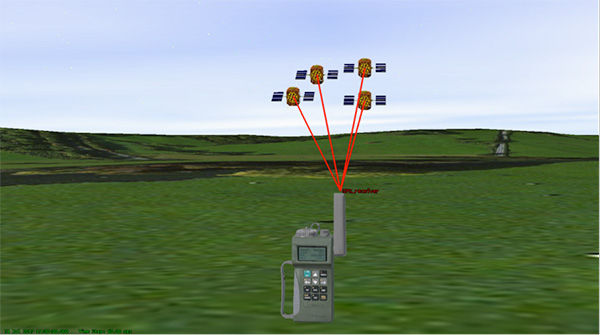
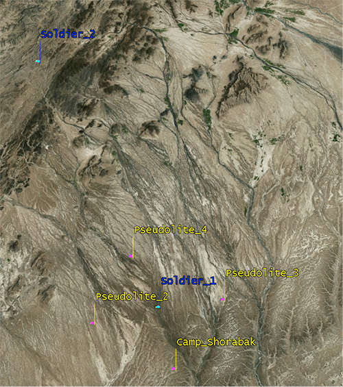
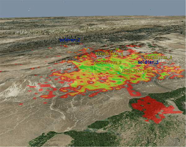
Let’s consider a scenario: a conflict in Helmand province, Afghanistan. An operating base is established at Camp Shorabak, where a pseudolite is operating, and three further pseudolites are deployed in the field. This is shown in figure Figure 3.
Figure 3. Scenario with four pseudolites. (Image: Michael Jones)
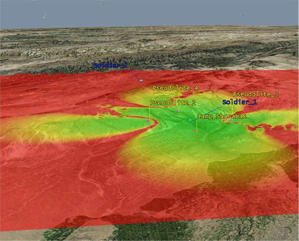
Taking a look at Figure 4, we can see what this means for HDOP. The regions shaded green represent locations where our HDOP is less than 2.5, and the red areas represent an HDOP greater than 50.
Soldier #1 is surrounded by the four pseudolites, which is a pretty nice arrangement: We get an HDOP of around 2.4. But if we now consider soldier #2, located a bit further out, we get a very different picture.
Here we have an HDOP of 64, which is fairly terrible. It’s not really that surprising looking at the geometry — to soldier #2 the pseudolites all appear in a similar direction. Soldier #2 cannot expect to achieve good positional accuracy in this arrangement.
Figure 4. HDOP for the Afghanistan scenario. (Image: Michael Jones)
So getting a good geometric spread of ground-based pseudolite locations could be a bit of a challenge, especially if the operating area is constantly moving and changing. The next thing to think about is getting enough height.
Getting the Height Right
When we perform positioning using GPS, we typically track several satellites, which have a range of elevations. Many GPS receivers will choose to ignore the satellites at low elevations, such as those within 5 degrees of horizontal, because those satellites are generally the least reliable. They may be partially obscured, and subject to more noise and fading.
Ground-based pseudolites all have very low elevations by definition. Unless the terrain is perfectly flat and smooth, pseudolites quickly become obscured. Even with flat ground, pseudolite signals will disappear behind the horizon after a few kilometers.
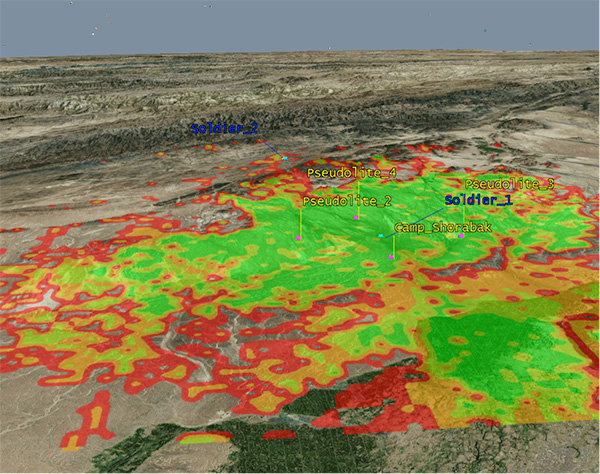
Let’s go back to our Afghanistan scenario again. This time, instead of looking at DOP, let’s look at the geographical coverage of our four pseudolites. Here we’ll assume that our user, the soldier, is 2 meters (m) high, and the pseudolite antennas are mounted at a height of 20m above the ground. That’s pretty high — the army will need to erect some masts.
Figure 5 shows what we get. The green areas are locations where our soldier can see all four pseudolites; yellow three, orange two, and red one. At all other locations, no pseudolite signals can be seen at all. You can quickly see that the range isn’t great — terrain, even small undulations in the ground, is a line-of-sight killer. Add some buildings and trees and the situation gets worse. Reduce the height of our pseudolites below 20m, and the situation gets worse. Soldier #1 can receive three pseudolite signals, but soldier #2 has no hope in this case.
Figure 5. Pseudolite visibility at 20m antenna height. (Image: Michael Jones)
Let’s raise the height of the antennas to a fairly crazy 100m above ground (Figure 6). As expected, we get much better coverage, but soldier #2 still has a problem. To get good signal coverage over any sizable area, you really do need to get those antennas as high as possible.
Figure 6. Pseudolite visibility at 100-m antenna height. (Image: Michael Jones)
Augmenting GPS
Often, we don’t want to rely on pseudolite signals alone. If GPS is available, we clearly want to make use of it, and so we want to use a mixture of both GPS satellites and pseudolites. Consider working in a region of sporadic GPS reception, such as an urban environment or forest. We can usually receive a couple of good GPS satellites, but we also need a couple of pseudolites to help us get a complete navigation solution.
Coming back to one of our original objectives, which is to avoid redesigning the GPS receiver hardware, we need to make sure that our receivers can receive and process both GPS satellite signals and pseudolite signals simultaneously. To achieve this, we can decide to make our pseudolites transmit GPS-standard signals, and make use of unassigned spreading codes to essentially create new satellites in the constellation.
But we quickly run into a problem. GPS satellites are always a distance of around 20,000 kilometers away, and the received signal strength is also fairly constant: around –158.5 dBW. This is a very small signal, as we all know, sitting well below the noise floor. When we suddenly bring high-power pseudolites into the mix, we have quite a nasty problem to deal with.
Near, Far, Wherever You Are
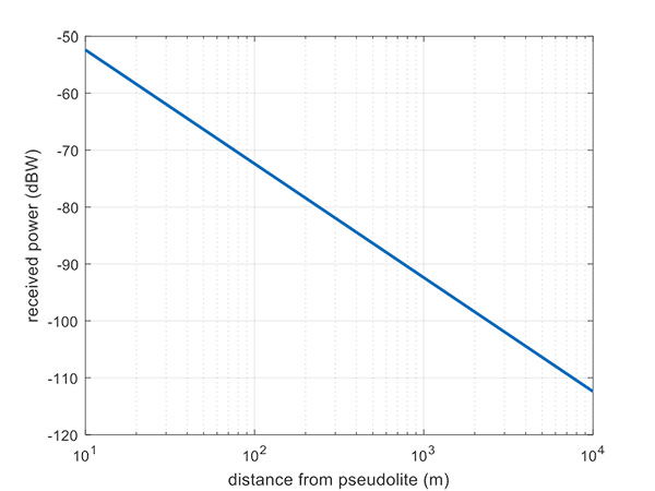
Let’s say, for argument’s sake, we have a pseudolite transmitting with a power of 1 watt. Conducting a basic link budget analysis gives us the plot below and suggests that, at a distance of 10 km from the pseudolite, we can expect to receive the signal at around –112 dBW. This is way above our GPS satellite signal level, but might be manageable by a receiver. Now consider a receiver at a distance of 100 m from the transmitter: we receive a power of –72 dBW, which is huge.
In our quest to augment GPS and make it more robust, we have in fact created a GPS jammer, and achieved exactly the opposite. As with any radio communications link, the received power is extremely sensitive to the distance (varying with the square of distance). In pseudolite terminology, this is known as the near/far problem.
Figure 7. Theoretical received power for a 1-W pseudolite, under ideal conditions. (Figure: Michael Jones)
The near/far problem has given engineers headaches for quite some time. Essentially, the problem comes down to: How can our GPS receivers handle such a massive dynamic range of expected signals? Especially if our objective is to avoid modifying the GPS receiver hardware, if at all possible.
How can a receiver handle the high power of a close-up pseudolite, which is to all intents a jammer, whilst simultaneously receiving the tiny GPS satellite signals from space? Various solutions have been proposed over the years, but one of the current favorite techniques involves pulsing the pseudolite signal.
The idea, then, is to only turn on the pseudolite periodically, essentially applying a duty cycle to the transmission. If a pseudolite isn’t transmitting, it can’t interfere with the normal GPS signals. There are a couple of things to take into consideration here:
What should the pulse duty cycle be, to enable both satellites and pseudolites to be tracked?
How does the GPS receiver behave when presented with alternating large and small signals?
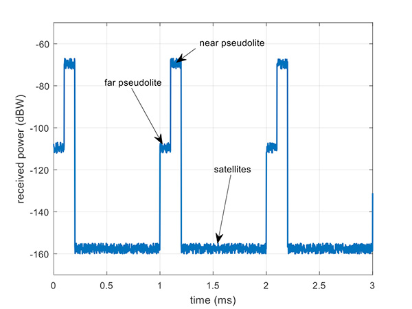
A mathematical analysis of duty cycle effects is beyond the scope of this column, but consider Figure 8 for a qualitative view. Here we have two pseudolites operating alongside GPS satellites. The duty cycle chosen here is for the pseudolite to be operational for 10% of a 1 millisecond integration period. This gives enough time, when the pseudolite is not transmitting, for the low-level GPS satellites to be tracked.
The second pseudolite, which is closer and therefore higher power, transmits for a further 10% slot after the first pseudolite. You can see that each additional pseudolite eats into the time available for tracking GPS satellites, and degrades the signal-to-noise ratio. There are some tricks you can play, such as transmitting multiple pseudolites at the same time if you know they will be similar power levels, but it can get complicated.
Figure 8. Received power versus time, for a pulsed pseudolite scenario. (Figure: Michael Jones)
The Importance of Gain Control
How the receiver copes with the large differences in received power level depends largely on the design of the RF front-end in the receiver. Most GPS receivers will have a certain amount of automatic gain control (AGC), which is a feedback loop designed to keep power levels constant. Many GPS receivers, though, simply aren’t designed with enough AGC to handle pseudolite-level signals (think GPS jammers again).
Military receivers, though, tend to have greater RF handling capabilities, and more bits in the ADC, so are better-suited to the situation. It is then a question of making sure the AGC loop responds in an appropriate time, compared to the duty cycle of pulses.
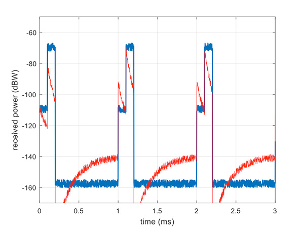
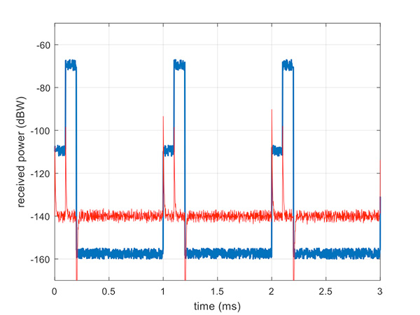
Figure 9 illustrates a slow AGC response, which is not particularly suitable. Compare this with Figure 10, where we have a fast AGC response, quickly adapting to the switches in power level. A receiver with this characteristic will be better able to track both pseudolite and satellite signals.
Figure 9. Pulsed pseudolites with slow AGC response (in red). (Figure: Michael Jones)Figure 10. Pulsed pseudolites with fast AGC response (in red). (Figure: Michael Jones)
Airborne Pseudolites
If you’ve read this far, you’ll now know that the main problems with ground-based pseudolites are lack of good geometry, signal blocking by terrain, and the horrendous near/far issues. Wouldn’t it be nice if we could raise the pseudolites to a really high altitude, and all these problems would go away? Wait, that’s the GPS satellite constellation!
Ok, let’s not put them that far up. But how about carrying pseudolites on high-altitude airborne platforms instead? Great idea, and that’s why this is a current thread of defense activity in various countries. High-altitude long-endurance (HALE) or HAPS (high-altitude pseudo-satellite; the clue is in the name) unmanned platforms can be used to carry pseudolites at high altitude.
This solution can provide excellent coverage, the pseudolites can be repositioned as necessary, and the near/far problem is also far less pronounced.
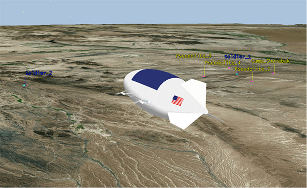
I leave you once again with our Afghanistan scenario, from the point of view of a high-altitude airship at 18,000 meters.
Figure 11. High-altitude platform, potentially carrying a pseudolite at 18,000 m. (Image: Michael Jones)
General Dynamics Mission Systems has introduced its HOOK3 combat survival radio.
The HOOK3 radio is 30 percent smaller and 40 percent lighter than the HOOK2 radio, and has a smaller, longer lasting battery, the company said.
In addition, the embedded GPS module has 32 channels enabling a faster position acquisition time, more accurate position reporting and better performance under forested or densely vegetated areas or near structures.
The radio transmits encrypted GPS, user identification, situation reports and other critical information to rescue teams and aircraft in short bursts to reduce the risk of detection. The radio can also use multiple GNSS.
The new radio provides direct line-of-sight voice and encrypted two-way data communications to help combat search and rescue teams quickly and accurately locate and rescue downed pilots and isolated military personnel, the company added.
The HOOK3 was designed using feedback from military personnel who rely on a survival radio in emergency situations. The new radio automatically activates and securely transmits location data when specific G-Force or the presence of salt water is detected by the radio.
“General Dynamics has delivered more than 36,000 combat search and rescue radios to 36 countries over the past 30 years,” said Paul Parent, a vice president of General Dynamics Mission Systems. “These radios have helped save the lives of military personnel isolated or in harm’s way during a mission.”
“The HOOK3 provides military personnel in emergency situations a highly reliable, easy-to-use, secure radio critical to their successful recovery.”
The General Dynamics HOOK3 radio is interoperable with all HOOK2 family radios, Quickdraw2 and SATCOM base stations currently used by U.S. and international military personnel.
The HOOK3 is designed for coalition operations, and the user-friendly transceiver is software-defined, enabling new features, waveforms and software upgrades to be added as they become available.
Drones have become a serious threat, able to penetrate airspace for surveillance or with an explosive payload.
The Islamic State has used weaponized drones against both Syrian and Iraqi forces; groups like Hezbollah and Hamas have sent drones into Israel and are said to be working on upgrading their UAVs for use in both intelligence gathering and offensive operations.
On April 27, Israel used a Patriot missile to take down a drone entering Israeli Airspace from Syria. At $3 million per missile, the Patriot system is an expensive way to down a device that may only be worth $200. Israel has also intercepted drones with fighter jets.
Systems developed by two Israeli companies provide less expensive — and quickly reactive — solutions.
The Drone Dome system uses Laser, RF and Radar. (Photo: Rafael)
Drone Dome.Rafael Advanced Defense Systems Ltd. has developed a radar and laser-beam system for detecting and destroying drones, with the company adapting its existing laser systems to handle the threat.
Once the system’s radar identifies targets, its laser system destroys them.
Drone Dome also features a jamming system for disrupting communications between the drone and its operator. Drone Dome’s range reaches several miles, but causes minimal interruptions to other systems in nearby urban areas.
The standard Drone Dome system comprises a RADA RPS-42 S-band multi-mission hemispheric radar, a Controp MEOS electro-optical (EO)/infrared surveillance suite, a communications package, and the C-Guard RD jamming and NetSense Wideband detection sensor systems developed by Netline. The UAV threat is neutralized by activation of directional GPS/GNSS and radio-frequency inhibitor/jammer devices.
The RPS-42 is a four-panel tactical air surveillance system delivering 360-degree coverage in azimuth and 90 degrees in elevation, with a detection range of 30 kilometers — including the detection of a minimum target size of 0.002 meters square at a range of 3.2 kilometers — at altitudes from 30 to 30,000 feet. The RPS-42 is designed to detect, track and classify all classes of UAV.
DROM Defense.ORAD’s DROM Drone Defense System can detect an approaching drone at more than 3.5 kilometers away and take command, neutralizing it and landing it far from the operator.
With a weight of 38 kilograms, ORAD’s DROM system comes pre-engineered and pre-assembled. It is mobile and easily deployed on land or at sea in any weather conditions and has an effective coverage range of 3.5 kilometers. It has a 2-kilometer neutralization capability.
Once intercepted, the system can land a hostile a UAV in a pre-defined location, keeping any intelligence it gathered out of enemy hands. It can also identify the location of the operator.
The system’s RF detection unit analyzes signal channels and radio transmissions to spot drones. Once detected, an alarm alerts the system operator.
ORAD has sold the system to clients in several countries including Portugal, Spain and Thailand. The company is in talks with Israeli agencies interested in purchasing the system.
L3 Technologies’ WESCAM division has received an order from Airbus Helicopters to provide 37 MX-15 electro-optical and infrared (EO/IR) imaging systems for installation on multiple fleets of H225M Caracal helicopters.
The systems will be installed in France before being delivered to two foreign governments for military deployment.
“This order expands L3’s international business base while creating a new market opportunity for our leading WESCAM products,” said Michael T. Strianese, L3 chairman and chief executive officer.
“L3 WESCAM is proud to have been chosen to supply its MX-15 systems, as it highlights our role as a trusted global supplier of advanced imaging technologies to the OEM marketplace,” added Mike Greenley, president of L3 WESCAM. “Additionally, it confirms that the highly specialized optics and leading technologies in L3’s systems continue to meet the needs of emerging mission portfolios, ranging from combative military to time-sensitive response and recovery operations.”
The first delivery of 19 units will support a variety of missions, including search and rescue, aeromedical evacuation and assistance and disaster relief.
The second delivery will provide a highly detailed, multispectral view of combat search and rescue, naval operations, medical evacuation and military transportation efforts to mission operators.
L3’s MX-15 can be configured with up to six imaging and laser payloads, each of which shares the highest level of stabilization. It incorporates a GPS receiver and antenna, with options available for a GPS time sync interface and GPS data interface.
Sensor options include a high-definition (HD) thermal imager, color low-light continuous zoom, daylight step zoom spotter, day/night spotter, laser rangefinder and a laser illuminator. L3’s MX-15 can be found on additional models of Airbus helicopters, including the H125 and UH-72A.
L3 WESCAM serves all segments of the airborne, land and maritime markets with advanced EO/IR imaging and targeting systems (MX-Series) and modular system solution kits (MatriX).
MX-Series turrets are operational across 74 countries and on more than 137 different types of platforms, and are supported by more than 14 globally deployed authorized service centers and a team of field service technicians who are available for dispatch 24/7 to anywhere in the world. L3 WESCAM is a unit of L3’s Sensor Systems business segment.
The government of Australia has launched the first $50 million Defence Cooperative Research Centre (CRC), announced July 6 by the minister for Defence Industry, the Hon Christopher Pyne MP.
The Defence CRC is a collaborative program that brings together academia, publicly funded research agencies and industry (particularly small to medium enterprises) to create an interlocking research and innovation capability focused on driving a Defence outcome.
The first Defence CRC will focus on Trusted Autonomous Systems to deliver game-changing unmanned platforms that ensure reliable and effective cooperation between people and machines during dynamic military operations.
“Existing autonomous and robotic systems that operate in the manufacturing and mining sector are effective in controlled environments, but not suitable for the uncertain situations in which Defence operates,” Pyne said.
“To be effective, Defence needs autonomous systems to be highly trusted, robust and resilient and this initiative will bring together the best researchers from industry and universities to develop the intelligent military platforms of the future.”
The CRC for Trusted Autonomous Systems will receive annual funding of $8 million with a maximum of $50 million over a seven-year period.
The CRC will be chaired by Jim McDowell, a businessman who has had an extensive career in the defence industry, and most recently at the University of South Australia.
“As Chair, Mr. McDowell will be responsible for leading the development of the research program and business plan and work with industry on transitioning the research results into capability outcomes,” Pyne said.
This is the first of several CRCs that the Australian government is announcing. Further CRCs will be established on projects also aligned with priorities in the country’s Next Generation Technologies Fund.
Defence will be a member of each CRC along with universities, research agencies and industry. Participating members will be selected on the basis of their research excellence and technology expertise.
“The CRC environment offers excellent synergies for Defence, industry and universities to collaborate closely on Defence innovation,” Pyne said.
The CRC is an initiative of the Next Generation Technologies Fund which complements the Defence Innovation Hub as the two core initiatives of the new Defence Innovation System outlined in the Government’s Defence Industry Policy Statement. These two signature innovation research and development programs, together with the Centre for Defence Industry Capability, deliver on the Government‘s $1.6 billion commitment to grow Australia’s defence industry and innovation sector.


 Surrounding sounds may not be a common way of determining location. But on the battlefield, warfighters need to know the direction of gunshots to enable a proper response.