The world population will soon need more food than we can currently produce. This article discusses some interesting GNSS agricultural innovations that have the potential for productivity improvements. Hemisphere, Septentrio, Case New Holland, and John Deere are all actively engaged in finding solutions using GNSS and are all overcoming technology and implementation limitations with new innovative approaches.
I’ve never felt entirely comfortable with GNSS in agriculture — basically because this is a specialized application area and discussion quickly turns to things like “yield, productivity, efficiency, costs, and inputs.” And if you haven’t lived in Iowa, or worked on a large acreage, or been employed by Deere — you just don’t have the vocabulary or the necessary technical background. But things have moved on in ag and all the technology is now basically enabled by GNSS, so maybe its time to take a new look.
It may be a good idea to try to understand the market drivers before we delve into the applications and who’s doing what. It seems that what drives Ag technology adoption is population growth. And people need food, and food production has to become more efficient for us to just keep up. If we can get 200 bushels (there’s another ag term) of crop per acre in a productive farm in North America, the challenge might be to improve how a typical small holding in India might move up from its current 20 bushels/acre by using ag automation. Or on a more global scale, over the next 50 years the world’s population is expected to require twice as much food, and a significant portion of this growth has to come from greater efficiency in food production from the same land.
So what are the technology drivers? It seems that auto-steer has been a major contributor, but GNSS accuracy improvements from decimeter wide-area networks, and more recently the widespread adoption of centimeter-level RTK, have improved machine guidance significantly. Then you have systems on tractors which can control these huge rigs and respond with complex “prescriptions” so field and crops alike specifically get what improves growth of specific crops. Gathering data as they proceed through these applications, farm databases are created and built upon, growing season after growing season.
Typical Asian farm operations.
Huge automated farm machine operating in North America.
I used to think that “down time” was a term more usual in the oil patch or in aviation, where high-value assets just cannot be left to idle because of a component failure or inadvertent human error. Down time for these huge ag rigs is big money nowadays, and systems are being constructed around their owners and farming customers to minimize non-productive time, lengthen their hours of productive use, and maximize the efficiency of the operation.
Hemisphere has been in the GNSS ag business for more than 20 years, and has evolved products from simpler mass-market light-bar guidance, folding in companies like Satloc, CSI, and Beeline technology and their applications, and growing its customer base in the process. As a consequence, ag systems opportunities in North America are now expanding into Brazil, Argentina, and elsewhere in South America where precision steering and application controls enable “controlled traffic” farming practices, variable rate input control, and simplification of high-value crop systems such as sugarcane where precise placement/spacing is required. An OEM partnership with Brazilian machinery manufacturer STARA has recently allowed integration of the eDriveX precision steering system and the A320/A321 dual-frequency RTK smart antenna with the STARA Topper 4500 application control terminal. Beyond South America, precision agriculture and automation is growing rapidly in China and Eastern Europe and is expected to ramp up over a much shorter period than seen in North America and Western Europe.
Hemisphere is tackling these opportunities with the Outback guidance series of products, which cover most of these different segments and degrees of Ag automation.
Outback S3 guidance display.
Outback AC110 automated rate and section control.
A321 RTK base station.
The Outback S3 combines a color touch screen with Crescent GPS receiver technology. This computer resource is at the core of the system where straight, contour, circle pivot, A+ direction guidance, and update B point is stored, controlled, and implemented. This display and control unit manages the automated steering system that drives the vehicle wherever the pattern requires and also controls automated section and chemical/fertilizer rate control. Automated section control is about preventing overlap and skip of inputs based on current GPS position and comparison with the vehicle’s actual location. Automated rate control is important for applying a constant rate of inputs regardless of changes in vehicle ground speed. Variable rate technology takes this a step further, allowing the system to automatically change the input rate as demanded by a stored application map related to field potential productivity zones. This program is customized for each farm/field and developed over time by gathering data on the growth of crops in response to various applications made in progressive growing seasons. This is where the real payback comes from in savings in previously wasted chemicals applied on the field — helps the economics of the operation, the efficiency of the application versus achieved crop growth, and minimizes the environmental impact of run-off.
RTK technology adoption is also growing in ag and machine control to enable centimeter-level vehicle steering to reduce skip/overlap and minimize soil compaction. In addition, RTK accuracy allows for new applications with accurate Z-positions such as water management and for better drainage, retention, and input management. For instance, more accurate elevation data can enable machine control for drain tile installation, surface ditch/drain installation, land leveling for even water distribution, and levee creation for irrigation retention. And accurate elevation maps combined with mapping layers for yield, soil-type and nutrient levels can give the grower a much clearer direction on how he may need to modify his input applications and drainage/irrigation strategy in order to maximize yield.
Hemisphere is clearly active in many phases of ag automation, including significant investments in the technology revolution which is bringing major changes to how automation can benefit farmers — but more about that later.
Septentrio in Belgium has also become involved in a number ag projects, mostly around the use of their AsteRx2eH dual-antenna receiver system.
Septentrio is working with customers who have applications in discrete crops such as flower bulbs, vegetables, and other ecological farming. These include mechanical weeding, which is needed in the very intensive and EU-controlled high-density farming in Western Europe. Designed to work with variable base-line lengths, this proven heading receiver continuously self-calibrates for antenna separation and has enjoyed success in many ag applications over the eight years it’s been in the field.
AsteRx2eH dual-antenna receiver.
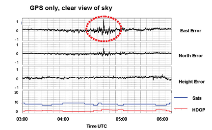
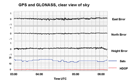
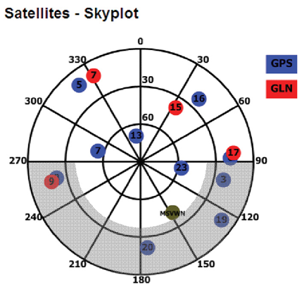
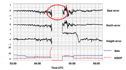
Then a problem of receiver interference encountered in farming applications in Russia became a practical application for Septentrio’s Advanced Interference Mitigation (AIM+) technology.
Near Tuymen in Russia, a local farming community was equipping their equipment with high-precision (RTK) GPS systems for autosteer and precision-farming applications. They had also set up a local base-station to provide the required correction signals. However, when they were trying to bring up the service, rovers receiving data from this base-station were unable to obtain an RTK position. Equipping the base-stations with Septentrio AIM+ technology, and activating the adaptive notch filtering feature, largely suppressed the interference and cm-accurate positioning became possible.
Case New Holland (CNH), the manufacturer of Case IH and New Holland agricultural equipment, also recognizes the importance of GNSS-based solutions to the future of agriculture production. A growing population will require that more food is grown on an ever-decreasing amount of land. GNSS-based solutions are allowing producers to meet this challenge.
Case IH Steiger 400.
New Holland T9.
CNH is seeing increased adoption of GNSS automation that is driven by the positive impact that agricultural producers are seeing in their operations. CNH partners with producers by providing GNSS solutions necessary for the producer to employ agronomic practices such as “site-specific farming.” This method, combined with machine automation, can improve profitability by applying the exact amount of inputs needed for optimal crop production. With the increased use of GNSS, awareness of how fertilization inputs are applied is proving to be the most accurate prediction mechanism for crop yields and is also increasing the safety of how this is done.
CNH farm equipment comes with options for factory-installed GNSS-based system solutions such as guidance, yield mapping, and product application control. CNH is responding to increased customer demand by providing more extensive GNSS solutions.
Now, whenever anyone thinks of automation in agriculture, it’s impossible not to talk about John Deere. Deere has been in the business of providing automation solutions to farmers on its platforms using GNSS for 16 years. The company felt this was so important to future growth that it integrated its own GNSS company (Navcom) into the Deere family. RTK corrections provided by many dealer networks in the U.S. and the StarFire worldwide correction distribution system form the core infrastructure necessary for its machine automation systems.
The highly accurate SF3000 is the latest addition to the Deere in-house receiver line. It comes with integrated StarFire and RTK capability, and in keeping with the tractor and machine installations it will see, is extremely rugged and reliable. Currently with integrated GPS and GLONASS, Deere intends to upgrade it for Galileo when it becomes available.
Deere SF3000 ag receiver.
Deere AutoTrac.
Deere AutoTrac uses high-precision GNSS combined with six-axis accelerometers and gyroscopes to measure vehicle dynamics/attitude and to automatically control vehicle steering. This enables hands-off agricultural operations and leads to large improvements in efficiency and productivity.
Overall, Deere Ag automation is aimed at enabling precision planting, precision seeding, and minimizing overlap — it used to be meters of potential overlap between successive passes down a field with huge rigs; nowadays it’s a matter of inches. These advances improve productivity, optimize water usage, and lead to precision-enabled decision-making, which brings us to the next revolution in ag automation.
Over the past 15 years, users have been collecting data in a manual fashion from in-cab devices such as yield monitors and controllers found in combines, sprayers, and planters. Growers and agricultural service providers traditionally have put this data into desktop application software, making it difficult and time-consuming to maintain and share large amounts of data especially between an ag service provider and the grower.
Deere’s new approach is called John Deere FarmSight enabled by telematics, and Hemisphere has gone as far as buying a company called Ag Junction with similar capabilities to join in this new approach as to how data gathered during automated ag operations is used, and how future operations can be monitored and controlled.
If you put a radio link in the cab of the tractor and use it to connect the system on the tractor to a central server, say at a local dealer’s, then data gathered by the equipment during regular operations can not only be collected in real-time, but can also be analyzed to develop prescriptions for successive treatments. Connecting growers, fertilizer/chemical/seed retailers, agronomist, and machinery supports increasing efficiency and data movement in the ag cycle.
Of course, you can also monitor equipment location and discover that it’s broken or moved from the place it’s supposed to be, so maintenance can be scheduled and theft can be reduced. Everyone will want more real-time support, direct use of data, asset tracking, and all the bells and whistles that being connected can bring to ag operations.
A new era in ag automation for sure, that could hopefully go a long way to achieving those major productivity increases in food production that we all will need in the future. We’ll learn more details about GNSS and ag from several experts in a GPS World webinar which is planned for August 2. Please watch for further announcements from GPS World.
Tony Murfin
GNSS Aerospace


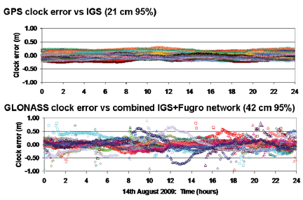
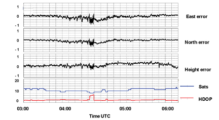
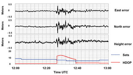
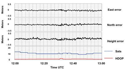
 RTK networks for agriculture are single-baseline solutions; the subscriber can only use one reference station at a time. There is no “network solution” or redundancy like there is in RTK networks used in the surveying and construction industries. Therefore, when a single reference station goes down, the subscribers in that area are down also.