Category: Applications

  • Directions 2023: BDS Development Continues Apace

    Directions 2023: BDS Development Continues Apace

    In 2022, the BeiDou Navigation Satellite System (BDS) continued to improve its service performance, expand global applications, and deepen and promote international cooperation.

    On Nov. 4, 2022, a white paper titled “China’s BeiDou Navigation Satellite System in the New Era” was published. The paper shows the continuous, stable and reliable operational capability of BDS, its applications achievements across the industries, international development with openness and integration, and unremitting pursuit of helping to build a community with a shared future for humanity and a better world.

    System Services Performances

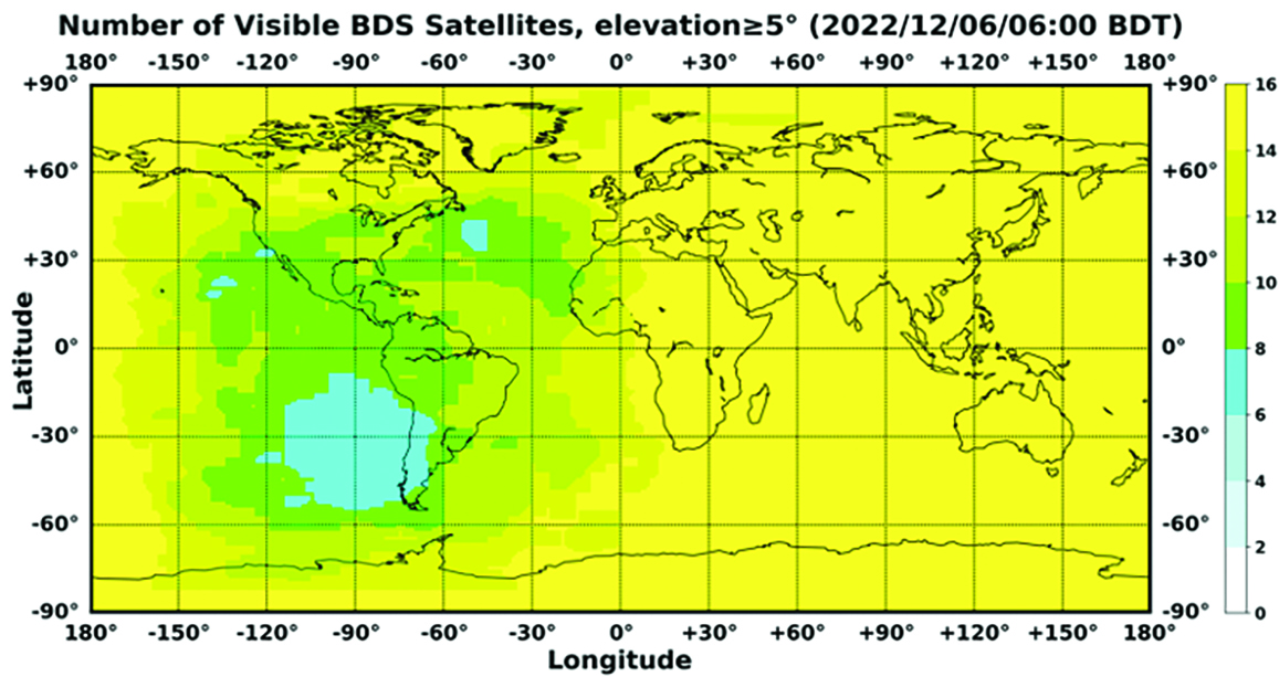
    In orbit are 45 BDS operational satellites, including 15 BDS-2 satellites and 30 BDS-3 satellites. Figure 1 shows the number of visible BDS satellites worldwide as of BDT 06:00 on Dec. 6, 2022.

    Picture1.Directions2023
    Figure 1. Number of visible BDS satellites. (Image: www.csno-tarc.cn)

    BDS has reached a continuity of 99.996% and an availability of 99%. The innovative constellation involves inter-satellite links, signal system optimization, intelligent operation and maintenance, software reconstruction and upgrading of in-orbit satellites, and global test and assessment.
    As measured by the International GNSS Monitoring and Assessment System (iGMAS), the BDS global positioning accuracy is less than 1.5 m horizontally and 2.5 m vertically (95% confidence) — better than the nominal service performance parameters.

    So far, the measured signal power spectrum envelope of the BDS satellites remains consistent with the superior signal quality; the signal-in-space accuracy of any BDS satellite is better than 4.6 m. The time offset between BDT and UTC (NTSC) remains within 26 ns.

    The BDS Coordination Framework has maintained consistency with the International Terrestrial Reference Frame 2014, and the accuracy is better than 3 cm. The orbital accuracy of the broadcast ephemeris of the BDS-3 medium Earth orbit (MEO) satellite is better than 0.5 m, and the clock offset of the broadcast ephemeris of the BDS-3 satellites is better than 5 ns.

    BDS concentrates on construction of the application infrastructure and has established four major characteristic service platforms:

    • Short Message Communication Service
    • Satellite-based Augmentation System Service
    • Search-and-Rescue Service
    • Ground Based Augmentation System Service.

    These platforms will expand and upgrade the applications and provide more efficient and convenient services for users.

    The BDS Short Message Communication Service platform realizes the interconnection with ground mobile communication systems and networks, and integrates the BDS short message communication functionality into smartphones without the need to change the SIM card or contact number.

    For the BDS Satellite-based Augmentation System Service platform, the system’s ground segment includes 30 monitoring stations and two data processing centers. The system will provide single frequency (SF) and dual-frequency multi-constellation (DFMC) services through GEO satellites. The Civil Aviation Administration of China has initiated and organized the technical testing and certification of SF service before applications.

    The BDS Search-and-Rescue Service provides users with distress alert information access and distribution, as well as return link services. It is currently at the initial operational stage with sound performances. The operational status of the BDS SAR payload has been submitted to Cospas-Sarsat.

    The BDS Ground-Based Augmentation System Service platform’s real-time positioning accuracy can reach 2 cm horizontally and 5 cm vertically. The post-processing accuracy can reach 2 mm horizontally and 5 mm vertically. At present, the BDS ground-based augmentation network has provided the A-BDS positioning and the BDS high-precision services for more than 1.5 billion users in more than 230 countries and regions, with services delivered 2 trillion times in total, equivalent to nearly 3 billion on average per day. BDS has provided high-precision positioning services for more than 20 million mobile phones in the country.

    The BDS Applications Industry

    The BDS applications industry has achieved sustainable development. In 2021, the total output of China’s satellite navigation and location-based service industry reached about 469 billion yuan (about 67.4 billion U.S. dollars), with a compound annual growth rate of more than 20%. A complete industrial chain covering chips, modules, antennas, boards, terminals and services has been established.

    Industrial applications. BDS has been fully applied in various industries — including transportation, agriculture, forestry and fishery, public security, disaster mitigation and relief — and has been integrated into infrastructure such as electric power, water conservation, finance and communications.

    As BDS applications fields expand, its in-depth applications have been growing as well. As of June 2022, more than 8 million BDS terminals had been installed in the transportation sector. More than 1.3 million terminals were used in the farming, forestry, livestock and fishing industries, and more than 1.8 million terminals were adopted by public security agencies. Large-scale BDS applications have been advanced in communication and timing services, meteorological monitoring, emergency response and disaster mitigation, and urban management. In emerging applications sectors, BDS has served epidemic prevention and control, telemedicine, caring for seniors, promoting the realization of intelligent health services that serve everyone, and accelerating intelligence and modernization in related fields.

    Mass market applications. BDS has been widely used in mass market applications, such as mobile phones and wearable devices. In the first half of 2022, among all types of smartphones that applied for network access in China, 128 supported the BDS-based positioning function. More than 130 million smartphones supporting BDS services were shipped, accounting for more than 98% of the country’s total volume. The BDS positioning service is used more than 100 billion times daily on average for a platform that supports mobile map navigation. In particular, mobile phones have been fitted with high-precision positioning services. Lane-level navigation has been implemented in eight cities in China, including Shenzhen, Chongqing and Tianjin. The first mobile phone in the world that supports BDS-3 regional short message communication services has been officially released, enabling users to send short messages through BDS.

    BDS international applications. BDS has been applied in more than half the countries and regions in the world, with more diversified application modes and application fields.

    BDS products, technologies and services have been recognized by more international users:

    • In Mozambique, BDS-based UAVs have greatly improved the efficiency of plant protection operations
    • In Lebanon, BDS-based high-precision technology has been successfully applied to the construction and measurement of the port of Beirut
    • In Burkina Faso, BDS supported surveying and mapping during the construction of hospitals to prevent and control local infectious diseases, such as COVID-19
    • In Saudi Arabia, BDS is widely used in fields such as surveying and the collection of geographic information, the construction of urban and municipal infrastructure, and the positioning of personnel or vehicles in deserts
    • In Asia, BDS-based high-precision positioning services are contributing to the monitoring of Sarez Lake Dam in Tajikistan, the completion of the China-Kyrgyzstan-Uzbekistan Highway, the China-Kazakhstan crude oil pipeline, and the routine operation of China-Europe Railway Express.

    International Cooperation

    Following the principles of openness, cooperation and resource sharing, BDS has been actively carrying out practical international cooperation and exchanges as well as facilitating the development of global satellite navigation.

    Multilateral cooperation. BDS representatives continue to participate in international activities under the framework of the United Nations International Committee on GNSS and other multilateral forums, to advocate joint development of global satellite navigation by contributing Chinese wisdom and proposals. BDS has also participated in international academic conferences in the field of satellite navigation, such as the Institute of Navigation meetings, the Munich Satellite Navigation Summit, and the Multi-GNSS Asia Conference.

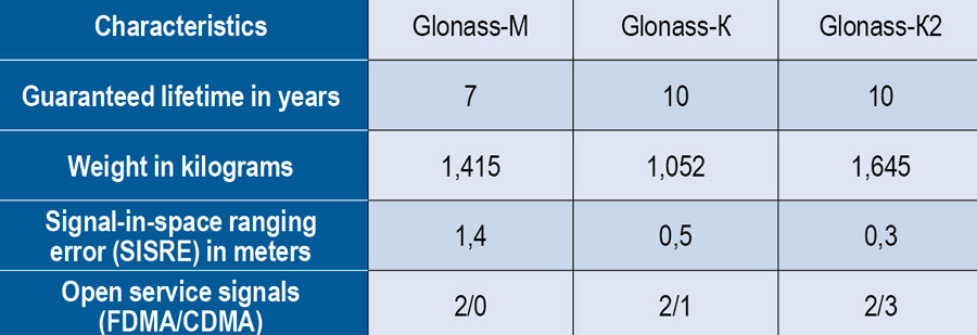
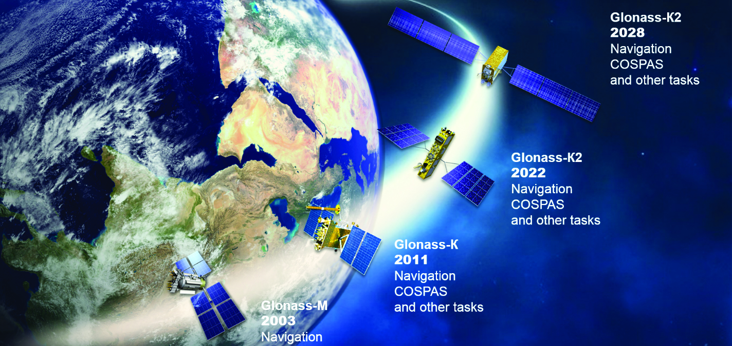
    Bilateral cooperation. The Ninth Meeting of the China-Russia Project Committee on Major Strategic Cooperation in Satellite Navigation was successfully held in September 2022. Under the framework of the Committee, BDS and GLONASS have carried out continuous cooperation in such areas as compatibility and interoperability, system performance testing and assessment, and joint applications. China’s Satellite Navigation Office signed cooperation documents in the field of satellite navigation with partners from the United Arab Emirates and the Arab Civil Aviation Organization, to carry out extensive cooperation and continue to deepen cooperation with Pakistan, Iraq, Thailand, Argentina, South Africa and other countries.

    International Standards. BDS is increasingly recognized by international organizations such as the International Maritime Organization (IMO), the International Civil Aviation Organization (ICAO), Cospas-Sarsat, IEC, 3GPP and RTCM. In November 2022, the BDS Message Service System (BDMSS) was ratified by the Global Maritime Distress and Safety System (GMDSS), making BDMSS the third GMDSS satellite communication system recognized by the IMO. The Declaration of Intent for Cospas-Sarsat MEOSAR Cooperation was signed between the cooperating agencies (from Canada, France, Russia, and the United States) of the International Cospas-Sarsat Program and the Maritime Safety Administration of China, meaning China formally becomes the provider of the Cospas-Sarsat space segment.

    The Future

    In the future, BDS will launch back-up satellites to ensure better performance by upgrading the constellation’s availability. While maintaining stable operation, BDS will speed up in combination with new technologies such as 5G, artificial intelligence and Big Data to build a more ubiquitous, more integrated, and more intelligent national comprehensive PNT system by 2035. BDS will continuously adhere to the development concept that “BDS is developed by China, dedicated to the world and aiming to be world class,” promote system development and make contributions to social development and construction of the community with a shared future for mankind.


    For analogous updates on the other three GNSS constellations, please see:

  • Directions 2023: GLONASS Renews Its Constellation

    Directions 2023: GLONASS Renews Its Constellation

    On Nov. 29, 2022, Russia launched the 51st Glonass-M satellite, completing a 20-year history that began on Dec. 10, 2003, with the launch of the first one. These satellites have been providing navigation signals in two frequency bands, L1OF and L2OF, to civil users since 2011.The average orbit lifetime for this type of satellite is more than 10 years, and 13 Glonass-M satellites operate beyond their guaranteed lifetime. The last set of seven satellites has been broadcasting the first CDMA civil signal, L3OC, by means of an additional antenna and onboard transmitter.

    Starting this year, the constellation will be renewed by Glonass-K and Glonass-K2 satellites, which provide CDMA signals to users. Furthermore, four Glonass-K satellites will be supplemented with additional Glonass-K satellites and the first Glonass-K2 satellite. The K2 satellite has passed all ground tests and is ready to be transported to the launch site (Figure 1). Table 1 lists the technical characteristics of GLONASS satellites.

    GLONASS image001
    Figure 1. Artist’s rendition of the Glonass-K2 satellite in orbit.
    Table 1. The evolutions of GLONASS satellites.
    Table 1. The evolutions of GLONASS satellites.

    The distinguishing feature of this satellite’s design is its two antenna arrays — one for CDMA signals with phase centers on the geometrical axis of the satellite, and the second for FDMA signals with phase centers shifted by 0.9 m relative to that axis.

    The optical reflector panel center is also located on the satellite’s geometrical axis and passed through its mass center. It seems to be a very interesting scientific task to estimate the satellite flight model parameters by International Laser Ranging Service stations with the objective to improve the accuracy of the navigation signals for both antenna arrays.

    Future GLONASS satellites will have a single antenna array for CDMA and FDMA signals (see Figure 2).

    GLONASS image002
    Figure 2. The evaluations of GLONASS satellites.

    For analogous updates on the other three GNSS constellations, please see:

  • Updates on NGS’s published heights in southeast Texas and NGS GPS on Benchmarks program

    Updates on NGS’s published heights in southeast Texas and NGS GPS on Benchmarks program

    First, happy New Year to everyone. As a follow up to my November 2022 column on the geodesy crisis, I’d like to highlight that the National Geospatial Advisory Committee (NGAC) of the Federal Geographic Data Committee (FGDC) just adopted a resolution on the need for the federal government to understand and aggressively address the US geodesy crisis. See below.  This is great news and, hopefully, the FGDC and others will follow up with discussions with other organizations such as the Office of Science and Technology Policy (OSTP) in the White House.

    Photo:
    Image: FGDC 

    Now for this month’s column. Last year the National Geodetic Survey (NGS) started suppressing height information in Southeast Texas (see my April 2021 and June 2021 columns).  See below for more information. Last year’s columns highlighted the potential effects of subsidence on published heights in the Houston, Texas, region which implied that most of the published heights, which are based on older surveys in the region, are not current or accurate.  At the time of NGS’s announcement, only 28 marks with orthometric heights were published on NGS datasheets in southeast Texas. Click here for more information and see below.

    This column will provide an update on the following: the current set of published orthometric heights in the southeast Texas region based on recent GNSS surveys performed during 2021 and 2022, NGS’s rules for estimating and publishing GNSS-derived orthometric heights using OPUS Projects, and the status of NGS’s GPS on Benchmarks program.

    Photo:
    NGS Announcement to Suppresses Height Information for Southeast Texas. Image: From NGS Website
    Photo:
    NGS Southeast Texas Orthometric Heights. Image: NGS

    This provides the benchmarks that are available to users (see also below).

    Photo:
    Link to Map SE TX Valid Ortho Heights. Image: NGS
    Photo:
    Image: NGS

    I always retrieve the latest published coordinates using NGS’s datasheet website routine. See the graphic below of the published NAVD 88 orthometric heights as of Nov. 20, 2022 (I used NGS’s monthly archive by State retrieval option).  There are currently 147 marks with published orthometric heights within NGS’s definition of the southeast Texas zone of subsidence. From mid-October to early December of 2022, another GNSS project sponsored by the Harris-Galveston Subsidence District (HGSD) was performed in the region.  In this project, 154 marks in the southeast Texas region were observed. The results of this project should be published and disseminated by NGS in the spring of this year.

    Photo:
    Latest Published Heights in Southeast Texas. Image: Dave Zilkoski

    The current version of OPUS projects allows the user to estimate NAVD 88 orthometric heights, providing they adhere to NGS’s recommendations and procedures. A presentation titled “Heights Suppression in Southeast Texas” by Boris Kanazir, NGS, provides guidance on estimating NAVD 88 orthometric heights using OPUS projects.

    See below for the requirements for number of occupations, duration of each session, and the spacing of marks with valid NAVD 88 published orthometric heights.

    The requirements include:

    • a minimum of two NAVD 88 control marks per new mark observed
    • a mark must be observed twice on different days and at different times of the day
    • the maximum distance between new marks and NAVD 88 control is between 30-50 km, based on session duration
      • 30 km for occupation sessions at least 2 hours
      • 40 km for occupation sessions at least 4 hours
      • 50 km for occupation sessions at least 6 hours
    Photo:
    Slide 42 of NGS Heights Suppression in Southeast Texas Presentation. Image: NGS

    The diagram below depicts how many marks with published NAVD 88 heights are required using a 30 km radius spacing.

    Photo:
    Slide 45 of NGS Heights Suppression in Southeast Texas Presentation. Image: NGS

    I like to think of this concept as drawing Venn diagrams around marks. See below for an example of the concept.

    Photo:
    Venn Diagram. Image: Dave Zilkoski

    So, what does this mean in the real world? The map below demonstrates the concept in the Houston-Galveston, Texas, region.  As shown, many of the 30 km circles overlap, indicating that in these overlapping areas there are two CORS with published NAVD 88 orthometric height.  This means that a user can occupy a mark for two hours and use the data from two CORS as NAVD 88 control.  Of course, the mark must be occupied twice for redundancy.

    Photo:
    30 km Radius Circles around SE TX CORS with NAVD 88 Heights. Image: Dave Zilkoski

    Increasing the radius to 40 km includes more overlapping areas.  This means that the user would have more overlapping areas with two CORS that have published NAVD 88 orthometric heights, but the marks would have to be occupied twice for at least four hours each time.

    Photo:
    Image: Dave Zilkoski

    Now, when you apply a 30 km radius around the current 147 marks that have published NAVD 88 heights, most of the region has overlapping areas (see below).  This means that the user could occupy two of the NAVD 88 marks along with any new marks for at least two hours.

    Photo:
    30 km Radius Circle Around all 147 NAVD 88 Marks in SE TX. Image: Dave Zilkoski

    The previous figure may seem confusing because of all the circles.  In the example below, based on only two marks, 11 marks fall inside the overlapping sections of the two circles. They could be established using the two NAVD 88 control marks that were used to make the 30 km circles.

    Photo:
    Example of Two 30 km Radius Circles. Image: Dave Zilkoski

    As depicted in my June 2021 column, the Houston-Galveston, Texas, region is subsiding.  The map below provides the latest estimates of subsidence in Houston-Galveston, Texas, region based on a Harris-Galveston Subsidence District (HGSD) report “Determination of Groundwater Withdrawal and Subsidence in Harris and Galveston Counties – 2021“ published in 2022.  Most of the rates are small, less than 0.5 cm/year, but some are greater than 1 cm/year.  This means that some marks may have subsided around 5 cm in five years.

    Photo:
    Estimate of subsidence in SE TX. Image: Dave Zilkoski

    The surveying and mapping community has done a tremendous job of increasing the number of published heights in the Houston-Galveston, Texas, region (from 28 to 147).  That said, the amount of movement in the Katy region is more than -2 cm/year (see box titled “Estimate of Subsidence in the Katy Area”).  That means, the marks in this area may subside 10 cm in five years.

    Photo:
    Estimate of subsidence in the Katy Area. Image: Dave Zilkoski

    Heights that change 10 cm cannot be considered NAVD 88 control marks. NGS’s OPUS Projects User Guide states the following about superseding a mark’s coordinates:

    “Users should review the newly adjusted coordinates on user marks to decide whether they recommend that the user mark be re-determined (re-published). Typically, this would happen if the coordinates have shifted by more than 2 centimeters horizontally or 4 cm vertically from the published coordinates marks.”

    Therefore, these marks in the Katy region may not be valid NAVD 88 control marks in about two years.  Even marks that are subsiding at 1 cm/year may not be valid NAVD 88 control marks in about four years.

    The community needs to maintain these marks to account for movement in the region. As previously stated, the Harris-Galveston Subsidence District (HGSD) has marks, denoted as PAMS, that are occupied continuously for a week several times throughout the year.  These PAMS and the CORS in the area could be used to estimate crustal movement rates and maintain a set of valid, published heights in the region.  See the boxes titled “ArcGIS Online HGSD Subsidence Rates” and “PAM 98 Subsidence Rate.” Additionally, the Texas Spatial Reference Center (TSRC) could provide the appropriate services to help maintain the published coordinates. The TSRC website states, “The technical mission of TSRC is to conduct basic and applied research contributing to NGS’s national Height Modernization program. TSRC is a repository for information used by researchers to develop improved understanding of elevation, geodetic and vertical datums in the state of Texas. The TSRC goal is to re-establish accurate evaluations throughout Texas in cooperation with qualified  geospatial scientists, professional engineers, and professional land surveyors.”

    Photo:
    ArcGIS Online HGSD Subsidence Rates. Image: Harris-Galveston Subsidence District
    Photo:
    PAM 98 Subsidence Rate. Image: Harris-Galveston Subsidence District

    In 2025, NGS will replace all three North American Datum of 1983 (NAD 83) frames and all vertical datums, including the North American Vertical Datum of 1988 (NAVD 88), with four new terrestrial reference frames and a geo-potential datum. As stated in my previous columns – April 2022, April 2021, June 2020 – the new reference frames will rely primarily on Global Navigation Satellite Systems (GNSS) as well as on a gravimetric geoid model.  These new reference frames will be easier to access and to maintain than the current NSRS. NGS will provide tools similar to the OPUS suite of routines that will facilitate users’ ability to submit data to NGS to maintain and publish survey marks. See the graphic below.

    Photo:
    Processing Data in the New NSRS. Image: NGS

    I would like to highlight that NGS has extended the cut-off date for submitting data for use in the 2022 Transformation Tool. The new cut-off date is Sept. 30 (see below).

    Photo:
    GPS on Bench Marks Cut-off Date Extended. Image: NGS

    In support of the GPS on Benchmarks program, on Jan. 12, NGS is hosting a webinar on using RTN data in OPUS Projects 5 for submitting GPS on Benchmarks data (see the box titled “NGS Webinar on OPUS Projects 5”)

    Photo:
    NGS Webinar on OPUS Projects 5. Image: NGS

    This column provided an update on the current set of published orthometric heights in the southeast Texas region based on recent GNSS surveys performed during 2021 and 2022, NGS’s rules for estimating and publishing GNSS-derived orthometric heights using OPUS Projects, and the status of NGS’s GPS on Benchmarks program. Additionally, it highlighted that the NGAC of the FGDC adopted a resolution on the need for the federal government to understand and aggressively address the United States geodesy crisis. This is a good step forward, and I hope that others will follow up with discussions with other organizations such as the OSTP in the White House.  Finally, “The Geodesy Crisis” white paper can be downloaded from the American Association for Geodetic Surveying (AAGS) website.

    I hope everyone has a happy new year filled with optimism, happiness and a generous amount of enthusiasm and fun.

  • EUSPA releases updated OSNMA documents

    EUSPA releases updated OSNMA documents

    EUSPA logoThe European Union Agency for the Space Programme (EUSPA) along with the European Commission, have published guidelines that specify the baseline applicable to the Galileo Open Service Navigation Message Authentication (OSNMA) receiver service provision phase. The new documents include the OSNMA Signal-in-Space (SIS) Interface Control Document (ICD), and OSNMA Receiver Guidelines.

    The OSNMA SIS ICD specifies, among other things, the interface between the Galileo Space Segment and the Galileo User Segment. This document is an addition to the Galileo Open Service (OS) SIS ICD.

    The OSNMA Receiver Guidelines provide generic instructions for the user segment implementation of the OSNMA functionality and complement the OSNMA SIS ICD. Additionally, the guidelines explain user capabilities and steps to implement to verify the authenticity of the Galileo navigation message.

    Both documents will be used for the upcoming OSNMA Service Provision Phase that will begin after the OSNMA Service Declaration. They have been developed as an evolution of the Galileo OSNMA User ICD for test phase (v1.0) and the Galileo OSNMA Receiver Guidelines for test phase (v1.1). Copies of the documents can be found here.

  • New California law targets OEMs of autonomous vehicles

    New California law targets OEMs of autonomous vehicles

    California lawmakers have passed a bill prohibiting OEMs of autonomous vehicles from marketing their vehicles as ‘fully self-driving.’ This law went into effect Jan. 1.

    This legislation was passed in mid-September of 2022 and states that manufacturers are prohibited from selling new passenger vehicles with autonomous driving features without fully disclosing their capabilities and limitations. Companies such as Tesla, and other OEMs in California, will no longer be able to market vehicles as ‘fully autonomous,’ as the new bill states that it is “considered a misleading advertisement.”

    Any violation of the new legislation will be punished as an infraction. Based on this, it is unclear what the exact punishment will be for OEMs that violate this policy.

    Senate Bill No. 1398 will be added to Section 24011.5 of California’s vehicle code. The full bill can be found here.

    Image: metamorworks/iStock/Getty Images Plus/Getty Images
    Image: metamorworks/iStock/Getty Images Plus/Getty Images
  • Atwell acquires Dempsey Surveying Company

    Atwell acquires Dempsey Surveying Company

    Photo:
    Image: sorn340/iStock/Getty Images Plus/Getty Images

    On Dec. 28, Atwell, a Michigan-based, full-service consulting, engineering, and construction services firm, announced its agreement to acquire Dempsey Surveying Company, expanding business in the Midwest. The deal is expected to close on Dec. 31.

    The acquisition of Dempsey Surveying Company, based in Cleveland, Ohio, broadens Atwell’s presence in the Midwest and expands surveying capabilities, as well as other services, to new and existing clients.

    Dempsey Surveying Company’s services include topographic surveys, construction staking, boundary services, Federal Emergency Management Agency (FEMA) flood elevation certificates, surface model TINs, GPS services, aerial mapping, and UAV services. The company has a variety of clients across several industries and has maintained more than 50 years of survey records.

    This is Atwell’s third acquisition this quarter. In November, Atwell acquired Cross Surveying, a Florida-based land surveying firm, and Ben Dyer Associates, a Maryland-based engineering firm.

  • Last first-generation Galileo satellite leaves test site

    Photo:
    Image: ESA

    On Nov. 11, the last Galileo satellite of first-generation series was shipped from ESA’s ESTEC Test Centre, Europe’s largest satellite testing facility. Galileo is Europe’s largest satellite constellation and one of the most accurate satnav systems in the world.

    Galileo’s development began two decades ago with two test GIOVE satellites, followed by a series of other operational launches to add to the constellation. The current constellation consists of 34 Full Operational Capability satellites, the initial two GIOVE satellites, and the Galileo In-Orbit Validation satellite. Galileo Second Generation satellites are already in development.

  • XenomatiX: Roadway assessment with solid-state lidar

    XenomatiX: Roadway assessment with solid-state lidar

    Multi-sensor clusters enable precise assessment of road conditions. (Photo: XenomatiX)
    Multi-sensor clusters enable precise assessment of road conditions. (Photo: XenomatiX)

    The success of higher levels of vehicular autonomy will depend on two types of roadway corridor digital twins: pre-mapped and augmented on the fly. No matter how well the corridors are pre-mapped, there will always be the need for the vehicle to be self-aware — not only of the proximity of other vehicles and pedestrians, but also of changes to fixed features. New vehicles are being provisioned with multi-sensor clusters, including GNSS, cameras, lidar, sonic and more. This provides an opportunity to more precisely assess the condition of the road surface, which affects the performance of vehicle suspension systems, tires, fuel efficiency and general wear and tear.

    “Imagine that your car navigation map system included roadway conditions,” said Karsten Bronowski, sales and business development manager for XenomatiX, “a global view where roads are color-coded based on their surface types and roughness. And all of this is mapped by systems like ours or added to the mobile systems mapping all the roads.

    “Our product actually came out of the automotive world, and we still have customers that use it as a reference system for active suspensions, for mass-spring damping systems,” Bronowski said. For these applications, the sensors were mounted facing forward for a preview mode. “We have worked with the Belgian Road Research Center and others with applications to readily provide the international roughness index.”

    XenomatiX was formed in 2013, focused on developing true solid-state lidar. “The idea was to get the motor out of lidar,” said Bronowski. “You have moving parts, you have wear and tear, the effects of vibration, problems with long-term reliability and with controlling temperature. With true solid-state lidar, you eliminate these issues.” Micro-electromechanical systems (MEMS) lidar systems still have moving, opto-mechanical components. Bronowski said that the solid-state systems feature a CMOS-based detector generating high-density point clouds in all weather conditions, and a multi-beam laser projector generating a high-resolution grid of points.

    The dual lidar sensor system gets its orientation and positioning from additional components, including GNSS and IMU. The system that Bronowski showed at Intergeo 2022 had Septentrio AsteRx-U3 GNSS/IMU units supporting dual antennas for heading. However, they are using other means to improve both relative and absolute positioning: “How we do this is one of our secrets. For one of our customers in Japan mapping local highways, we proved to have excellent compensation, even tracking precisely through a 4-kilometer-long tunnel.”

    XenomatiX has developed software to analyze data for many applications, automate feature recognition, and even validate other data. For instance, one customer in the United States is a big player in the satellite imaging sector that wants to match that data with pavement markings the XenomatiX system picks up.

    While there is a needed calibration step and the requirement to align the detector for the dedicated measurement vehicle, sensor systems such as this can be put on just about any type of vehicle — on- or off-road. The driver does not need to intervene much, and the processing is done on a standard PC or laptop. “The customer does not care about the systems, just the data that comes from it,” Bronowski said.

  • CHC Navigation: UAS use on the rise for corridor mapping

    CHC Navigation: UAS use on the rise for corridor mapping

    Tactical-grade IMUs enable UAVs to achieve the same locational accuracy as ground-based systems. (Photo: CHC Navigation)
    Tactical-grade IMUs enable UAVs to achieve the same locational accuracy as ground-based systems. (Photo: CHC Navigation)

    We often hear the anecdote about an early lidar scanner that could take a shot every few seconds, yet it held a value proposition for certain applications. As the capabilities of successive mapping and surveying systems change rapidly, so does the conventional wisdom about which are best for various applications. Transportation corridor mapping — be it for improvements design, as-built surveys, asset management or digital twinning — has always been a balancing act between precision and efficient large-scale data capture.

    “I remember 15 years ago, during my university time, the scanner was the size of a dining table,” said Andrei Gorb, segment manager for mobile mapping and unmanned aerial vehicle (UAV) systems, CHCNAV. At the top end of the mapping food chain were terrestrial scanners, targets, bore sighting, and registering point clouds mostly manually. As cumbersome and time-consuming as the legacy tools and methods were, these options still offered efficiency gains compared to conventional surveying with total stations. Then a decade ago, mobile-mapping systems began to change that paradigm. Departments of transportation found that mobile-mapping systems could meet their requirements for many design projects, and certainly for asset inventory and management. Unmanned aircraft systems (UAS) were not quite there yet.

    The tech used depended on the application. “First, there was road maintenance, to understand the road condition,” Gorb said. “Previously, UAS did not meet the high requirements: centimeter in absolute and millimeter in relative. We now have mobile-mapping solutions, from us and other suppliers, that can be in the 8-9 mm absolute accuracy range on short road surfaces.” Yet for many transportation applications, the absolute accuracy may not be as important as the relative precision. This is where years of development in UAS has made the difference.

    CHCNAV was not alone in recognizing that the gap was closing, and the company planned ahead. “Previously, UAS would fly for under an hour, and were mostly carrying cameras or early lidar, which was not suitable for highways,” Gorb said. “A few years of development, and we see it is practical to meet requirements with UAS flying between 50 and 100 meters — in Europe, many local regulations forbid flying above 120 meters anyhow.” Gorb attributes the advances to lidar sensors that UAS can carry. These sensors have become much better and less expensive. Plus, platforms like vertical-take-off-and-landing (VTOL) systems can stay in the air much longer.

    The UAS boom of the past 10 years saw the dominance of consumer-prosumer market UAV platforms becoming quite commoditized, with certain vendors gaining majority market share. CHCNAV, instead, sought to develop enterprise solutions, for both mobile and UAS systems — large-platform rotor, fixed-wing and VTOL platforms. The company offers an amalgam of hardware and software, from Riegl scanner heads on some of their mobile-mapping systems to Honeywell inertial navigation systems (INS) for some of their UAS solutions.

    Gorb echoes what we hear from many mapping practitioners, saying ground-control points are not as necessary in the densities required for legacy mobile and UAS mapping. He explained that everything from strip adjustments to processing of GNNS/IMU data has tightened both precision and accuracy. “We have a tactical-grade IMU in both our mobile mapping and UAS solutions, for a high-end trajectory,” Gorb said. “So, it means that we can get the same high-accuracy point cloud for highways from the ground and the air perspectives.”

  • Trimble: European company reduces emissions and improves deliveries

    Trimble: European company reduces emissions and improves deliveries

    Trimble Maps enables a shipping company to offer one-hour delivery windows. (Photo: Trimble)
    Trimble Maps enables a shipping company to offer one-hour delivery windows. (Photo: Trimble)

    To reduce its emissions, DPD Deutschland — a franchise of DPDgroup, one of the largest international parcel carriers in Europe — has asked Trimble Maps to help optimize its operations. DPD Deutschland’s parcel supply chain covers 80 franchise depots, 9,500 employees and more than 13,000 drivers, delivering about 2 million packages to businesses and consumers per day via a mixed fleet of vehicles, including electric ones.

    DPDgroup has a vision to become the international standard in sustainable delivery by 2030. Per parcel, it has reduced its CO2 emissions by 18.8% since 2013 and is on track to reach a 30% reduction by 2030, according to Trimble.

    One of DPD’s most popular service offerings, called Predict, allows parcel recipients to track the progress of their deliveries in real time, with an estimated one-hour delivery window and updated notifications along the way. Since 2014, Trimble Maps’ portfolio has helped calculate this one-hour delivery window and provided turn-by-turn navigation to DPD drivers, resulting in less overall travel time, more successful first-time deliveries and reduced emissions.

    DPD was the first, and still is the only, parcel carrier in Germany that provides recipients with an estimated one-hour delivery window, the company says, calculating it for every parcel. The service is made possible in part by the integration of Trimble Maps’ route optimization and mapping web services platform, known internally as DPD Maps. Recipients can reschedule deliveries as needed for future days and times, or perhaps to a convenient drop-off location. This reduces emissions created by multiple return trips.

    DPD Maps calculates an optimized route for drivers, who are then able to manually sort the stops and change the route to best fit their preferences. Once routes are locked in, Trimble’s commercial navigation application, CoPilot, provides drivers with real-time directions. Once a driver’s route is complete for the day, DPD can compare the actual route taken with the optimized route DPD Maps calculated in an easy-to-understand view that can be analyzed by the driver and the depot.

    DPD Maps allows the company to visualize, share and discuss results with different stakeholders within the organization. The solution also allows drivers to plan out their day as they see fit, while giving the back office access.

  • Orolia: Distress locator enhances aviation safety

    Orolia: Distress locator enhances aviation safety

    Airbus will install Orolia’s Ultima-DT emergency locator transmitter on its aircraft. (Photo: Airbus)
    Airbus will install Orolia’s Ultima-DT emergency locator transmitter on its aircraft. (Photo: Airbus)

    This fall, Orolia’s Ultima-DT was certified as an emergency locator transmitter with distress tracking (ELT-DT) by Cospas-Sarsat, an international humanitarian search-and-rescue system. Cospas-Sarsat uses space-based technology to detect and locate model 406 emergency beacons carried by ships, aircraft or individuals venturing into remote areas — often inaccessible by GNSS signals. The system consists of a network of satellites, ground stations, mission control centers and rescue coordination centers that work together when a 406 beacon is activated.

    I spoke about the certification with Christian Belleux, director, Aviation & Defense Beacons for Orolia.

    Matteo Luccio (ML): Has Orolia produced aviation safety products in the past?

    Christian Belleux (CB): Orolia has been supplying emergency locator transmitters for aviation since 1995 on a very large number of platforms to OEMs and airlines for use on commercial aircraft — Airbus, Boeing, Embraer and Bombardier aircraft. Orolia is also participating in industry groups creating standards (Eurocae, RTCA, ARINC) or contributing to the progress of the Cospas-Sarsat search-and-rescue satellite system as a member of the Expert Working Group.

    ML: What are the key challenges in making an aviation ELT?

    CB: With new requirements for lithium batteries and new regulations introducing distress tracking, recent times have been rich in innovation. We were granted the first ETSO certification ever for an ELT-DT and the same product, the Ultima-DT, was also the first ELT to be certified for its lithium battery.

    ML: What did Cospas-Sarsat certification of the ELT-DT entail?

    CB: The ELT-DT is a new type of beacon with a new communication protocol. The labs performing the certification tests must be approved by Cospas-Sarsat before we can apply. Then the Cospas-Sarsat organization and infrastructure must be updated to receive and consider the new ELT-DT protocol. The Cospas-Sarsat certification of our ELT-DT means that it complies with the performance requirements described in Cospas-Sarsat standards and can communicate with the infrastructure.

    ML: What is new about an ELT-DT?

    CB: The principle of an ELT-DT is to activate in flight before a crash, as opposed to a legacy ELT that is activated by the shock of a crash. This means that the aircraft and the ELT-DT can analyze the health of the aircraft and its parameters, and activate if a catastrophic event is about to occur. Once activated, the ELT-DT transmits a high-rate distress signal that makes it possible to track the aircraft until it crashes. The ELT-DT contains its own GNSS receiver that is independent the aircraft’s navigation system.

    ML: Did you cooperate closely with one or more avionics manufacturers to develop your device?

    CB: Orolia was in very close contact with Airbus, which designed the avionics components.

    ML: Do you already have contracts with airlines or aircraft manufacturers besides Airbus for the Ultima-DT?

    CB: We have several contacts with aircraft manufacturers and airlines interested in the Ultima-DT.

    ML: When will the first batch of the ELT-DT / Ultima-DT be operational?

    CB: We started flight tests months ago at Airbus and delivered production units. Airbus soon will announce its first delivery of an aircraft equipped with the Ultima-DT.

  • Hexagon | AutonomouStuff: Open-source software powers autonomous shuttle

    Hexagon | AutonomouStuff: Open-source software powers autonomous shuttle

    Hexagon | AutonomouStuff’s hardware rack inside the Ford Transit shuttle. (Photo: Hexagon | AutonomouStuff)
    Hexagon | AutonomouStuff’s hardware rack inside the Ford Transit shuttle. (Photo: Hexagon | AutonomouStuff)

    When it comes to ground transportation, most of the R&D regarding GNSS is aimed at developing driver-assist systems and, ultimately, driverless cars and trucks. For that purpose, GNSS receivers are integrated with inertial navigation systems, radar, lidar, computer vision and ultrasonics.

    Leveraging decades of robotics experience and knowledge of control algorithms, AutonomouStuff, part of Hexagon’s Autonomy & Positioning division, has developed a software stack for autonomous vehicles based on the Apollo open-source software stack.

    “Think of this software stack as a brain powering the autonomous platform,” said Kevin Fay, product manager for Hexagon’s platforms and vehicle software business. The software stack can be customized across platforms and to meet equipment needs.

    Most recently, in a collaborative project with the National Advanced Driving Simulator at the University of Iowa, AutonomouStuff worked with the Automated Driving Systems for Rural America project to outfit a Ford Transit 350HD shuttle for autonomous operation. First, it created a drive-by-wire system that enabled electronic control of the vehicle, and then it installed positioning, navigation and perception sensors. The result is a platform ready to be autonomous as soon as the software stack is integrated.
    Rural roads — which have a wider range of speeds than urban ones — may be encumbered by wildlife or heavy equipment. They also vary in surface from asphalt to gravel, providing a particularly challenging test environment for the autonomy software.

    “The Iowa vehicle has done a sizable amount of automated driving on a combination of urban and rural roads, where traditional sensing falls flat,” Fay said. “It has excelled in areas such as gravel roads that have limited or no lane markings, or are narrower than normal. We deployed it earlier this year to do things such as traffic-light detection with the cameras on board, so that it navigates traffic-light intersections appropriately.”

    While rural roads are generally free of the GNSS multipath challenges presented by urban canyons, they also provide fewer navigation landmarks. Another challenge is inclement weather. During snowstorms, Fay pointed out, country roads might be unplowed. “If you run on the right lane of the road all the time, you might be out of the ruts that are on the road, and then you’re struggling to get through.” The vehicle must learn to navigate appropriately in those conditions.

    The University of Iowa Ford Transit shuttle is a limited deployment, mainly to collect data for research purposes. Meanwhile, it is giving real rides to residents, though with a safety driver. “They’re always attentive, but their hands will be next to the wheel,” Fay said. “There will be times where they may have to take over.”

    Other universities and companies are using the platform to further their autonomy programs. Most of them are doing urban driving in complex routes with live traffic, for a total of a dozen vans nationwide.

    Hexagon equips the vehicles with a variety of sensors, including a front-mounted adaptive radar, a roof-mounted Velodyne lidar, a roof-mounted NovAtel GNSS receiver and cameras mounted inside the vehicle. “Which ones we provide depends largely on the customer and on which software they’re deploying,” Fay said. “We provide our customers a complete package that can be used with minimal work out of the box. It has the software, the interface to the vehicle, and sensors on it. But we can also provide them with a vehicle that simply has an interface for control, and they add their own computer and software on top of it.”
    Hexagon’s first Ford Transit was deployed in 2021. The company released the current version in the spring of 2022, and the Iowa project is slated to run through the middle of 2023. “We’ve not had something running in live traffic before,” Fay said, “so it allows us to continue to grow our skill sets and our overall expertise.”