By Kazuma Gunning, Juan Blanch and Todd Walter, Stanford University, and Lance de Groot and Laura Norman, Hexagon Positioning Intelligence
UAV and autonomous platforms can greatly benefit from an assured position solution with high integrity error bounds. The expected high degree of connectivity in these vehicles will allow users to receive real-time precise clock and ephemeris corrections, which enable the use of precise point positioning (PPP) techniques.
Until now, these techniques have mostly been used to provide high accuracy, rather than focusing on high-integrity applications. The authors apply the methodology and algorithms used in aviation to determine position error bounds with high integrity (or protection levels) for a PPP position solution.
PPP techniques can provide centimeter accuracy without local reference stations in kinematic applications. These techniques have so far mostly been used to provide high accuracy, and it is only recently that they have been proposed to provide integrity, that is, position error bounds with a very low probability of exceeding them.
There has been preliminary work on the application of integrity to PPP, but it remains a challenge to translate the benefits of PPP to accuracy while maintaining high integrity. Most of the integrity work in PPP and real-time kinematic (RTK) has dealt more with the ambiguity resolution process under nominal error conditions and less on the integrity of the position solution under fault conditions.
The authors overview their PPP filter implementation, and describe the threat model as well as two classes of integrity algorithms: solution separation and sum of squared residuals based (also called residual-based [RB], a misnomer, as all autonomous integrity monitors are based on the residuals.)
They present data sets used to evaluate the algorithms, compare the protection levels (PLs) obtained with different algorithms, and present the results obtained with the most promising PL formulation in four different data sets: static, dynamic in open-sky conditions, dynamic in midtown suburban conditions, and in flight.
Concluding, they state: “We have formulated RAIM protection-level formulas using either solution separation or the sum of residual squares. Both formulations consist of straightforward adaptations of snapshot RAIM to a Kalman filter solution.
“For solution separation, we have shown an implementation where the computational cost of running a bank of filters is far from being proportional to the cost of one filter. Instead, we could run 50 additional filters for the cost of one.
“For residual based RAIM we have developed a set of formulas to update the sum of square residuals from one time step to the next one. Because this test statistic is exactly the same as the one used in snapshot RAIM (when we consider the problem as a batch least squares), we could use the formula that ties the slope of a fault mode to the standard deviation of the solution separation. The slope can therefore also be updated recursively.”
Finally, “we have refined the PPP filter, added one scenario (suburban driving conditions), and examined the effect of considering multiple faults in the formulation of the test statistics and the protection levels. The results are very promising: protection levels below 2 m appear to be achievable, and the computation load is lower than expected.”
The Trimble TDC150 handheld is a new field computer designed for GIS data collection, inspection and management activities.
The TDC150 provides users with a rugged device that has the flexibility of a handheld, a modern interface with open Android operating system, and scalable high-accuracy positioning for professional field workflows.
The TDC150 provides advanced GNSS capabilities in a durable, ergonomic and lightweight form factor. With a built-in GNSS antenna, the TDC150 is a scalable solution that allows customers to choose their desired accuracy. Easy-to-use and carry in the field, it features a bright 5.3-inch sunlight-readable touch screen and an all-day battery for continuous work on the jobsite, the company said.
The handheld comes with Google Mobile Services certification to run Google core applications and access thousands of apps on the Google Play Store. Professional GIS field applications, including Trimble TerraFlex software — a cloud-based solution that enables users to easily collect, manage and edit their geospatial feature data — are supported, as well as Trimble Penmap for Android software and Esri’s Collector for ArcGIS mobile app.
A new innovative TerraFlex workflow uses the TDC150’s onboard rear-facing camera to capture features. This visual aid shows users when the camera and receiver are aligned over features, enabling horizontal centimeter accuracy when holding the device.
“The mapping and GIS industry, including utility companies, local government, and environmental management agencies, look to Trimble for continued innovation,” said Rachel Blair-Winkler, business area manager for Trimble Mapping & GIS solutions. “Adding the ability to get the level of horizontal accuracy required in a handheld configuration without the need for an external pole and antenna, and the new camera-based data logging workflow, gives our customers the flexibility to accomplish more while out in the field.”
Detailed 3D maps of the iconic and historic Notre Dame Cathedral in Paris hold out hope for accurate reconstruction after it was devastated by a massive fire April 15. Both the ceiling and the spire were destroyed, as well as internal woodwork.
But the information to restore the cathedral is abundant. Besides photos, in 2015 art historian Andrew Tallon used laser scanners to create an immaculately accurate model of the cathedral, as reported in this National Geographic feature.
Laser scans, with their exquisite precision, don’t miss a thing. Mounted on a tripod, the laser beam sweeps around the choir of a cathedral, for example, and measures the distance between the scanner and every point it hits. Each measurement is represented by a colored dot, which cumulatively create a three-dimensional image of the cathedral. “If you’ve done your job properly,” says Tallon, the scan is “accurate to within five millimeters [.5 centimeter].”…
Tallon figured out how to knit the laser scans together to make them manageable and beautiful. Each time he makes a scan, he also takes a spherical panoramic photograph from the same spot that captures the same three-dimensional space. He maps that photograph onto the laser-generated dots of the scan; each dot becomes the color of the pixel in that location in the photograph.
As a result, the stunningly realistic panoramic photographs are amazingly accurate. At Notre Dame, he took scans from more than 50 locations in and around the cathedral—collecting more than one billion points of data.
Assassin’s Creed Unity. Another source comes from a video game company. Immaculate models of the cathedral were collected for the creation of the best-selling “Assassin’s Creed: Unity,” where the hero/player is able to climb both the outside and inside of the massive edifice.
An artist for the Ubisoft game, Caroline Miousse, told The Verge:
In the case of the Notre Dame, easily the biggest structure in the game, it meant recreating a version of the cathedral that didn’t actually exist at the time. Level artist Miousse spent literally years fussing over the details of the building. She pored over photos to get the architecture just right, and worked with texture artists to make sure that each brick was as it should be.
After 2020, Super Cruise will will be available on all General Motors brands (Photo: GM)
Trimble has announced the availability of Trimble RTX Auto, a GNSS software library written for use in safety critical automotive applications.
The RTX Auto library can be integrated with any GNSS device and enables the decoding of Trimble’s RTX correction stream for centimeter-level absolute positioning accuracy, the company said.
RTX Auto works with other on-vehicle sensors to deliver a positioning solution that satisfies advanced driver assistance systems (ADAS) and autonomous driving requirements.
RTX Auto is both Automotive Safety Integrity Level (ASIL) and Automotive Software Process Improvement and Capability Determination (ASPICE) certified. These certifications validate that Trimble RTX Auto meets functional safety requirements for ADAS and autonomous applications in the auto industry.
“For over 35 years, Trimble has been at the forefront of positioning innovation, accelerating productivity for our users,” said Patricia Boothe, vice president of Trimble’s Advanced Positioning Division. “RTX Auto takes our technology leadership into functional safety applications and allows the automotive industry to leverage Trimble’s leading RTX correction technology. Trimble RTX technology is helping to safely accelerate vehicle autonomy, transforming how the world drives.”
While other correction service providers are validating their ADAS positioning products and services in test environments only, Trimble is on the road today providing RTX-based absolute positioning within General Motors’ Super Cruise, a hands-free driving system for the freeway.
Designed for demanding positioning and heading applications
The P2 Elite GNSS sensor. (Photo: CHC Navigation)
CHC Navigation has released the P2 GNSS sensor series, which the company says provides high-accuracy positioning and heading in a compact, rugged enclosure.
The P2 GNSS sensor series is suitable for a wide variety of applications such as reference station, marine systems, unmanned navigation, industrial automation, robotics and machine control.
Integration. The P2 GNSS series is designed to significantly reduce system integration efforts by combining numerous connectivity interfaces including RS232, low-latency PPS output, Ethernet, CAN bus protocol and a comprehensive web interface for configuration set-up.
The series integrates the latest GNSS technology in an extremely rugged IP67 and lightweight enclosure. It delivers reliable, uninterrupted, high-accuracy, real-time positioning and heading measurements.
Scalable with 3 models. The P2 GNSS series is available in three different models to match various application requirements.
The P2 GNSS sensor offers cost-effective and powerful real-time kinematic (RTK) positioning.
The P2 Pro GNSS adds a dual-antenna input for precise heading data.
The P2 Elite integrates additional 4G and UHF modems to provide a powerful, all-in-one, GNSS sensor.
“The P2 GNSS sensor series is leveraging our expertise in providing high-performance and reliable GNSS solutions,” said George Zhao, CEO of CHC Navigation. “Back-up by CHCNAV’s professional integration support, the P2 GNSS sensor series offers exceptional feature set to system integrators and machine manufacturer partners.”
Hemisphere GNSS has launched a single-frequency, multi-GNSS Vector V200 smart antenna with integrated Atlas L-band designed for general marine applications and markets.
The V200 is being featured in the Hemisphere/Saderet stand (K12) at Ocean Business 2019 in Southampton, UK, from April 9 through 11.
Powered by Hemisphere’s Crescent Vector technology, the V200 is a multi-GNSS compass system that utilizes GPS, GLONASS, BeiDou, Galileo, and QZSS (with future firmware upgrade and activation) for simultaneous satellite tracking to offer heading, position, heave, pitch and roll output.
With support for NMEA 0183 and NMEA 2000, integrating Atlas L-band corrections, and continuing to offer ease of installation, the V200 packages and offers exceptional value and performance. The V200 excels in providing accurate position and heading information to autopilots, chart plotters and other general marine navigation applications.
The all-in-one V200 GNSS compass combines Hemisphere’s Crescent Vector H220 OEM board, two superior multipath and noise-rejecting antennas (spaced 20 cm apart), a multi-axis gyro, and tilt sensors in a single easy-to-install and use enclosure.
The V200 delivers 1.5 degree (or optional 0.75 degree) heading accuracy and Atlas L-band accuracies of 30 cm to 60 cm and offers instantaneous sub-meter accuracy and DGPS-level accuracy.
Measuring only 35 cm in length, the V200 can be either pole or surface mounted and comes in either 5- or 12-pin options that require only a single power/data cable connection for fast and reliable installations, even in the presence of strong radio transmissions.
“The Vector V200 GNSS compass represents significant enhancements to our industry-leading models it replaces, providing even greater performance, improved robustness, and excellent value,” said Miles Ware, director of marketing at Hemisphere. “Users now have an even higher performing all-in-one Vector for their marine applications with the addition of BeiDou, Galileo and QZSS, as well as Atlas L-band corrections.”
Photo: U.S. Air Force / Staff Sgt. Scott H. Spitzer
Much development has been necessary to enable the new M-code capability on more than 700 weapon systems that require it. This article overviews M-code, the updates to antenna and receiver technology to make these varied platforms M-code ready, and perspectives from key stakeholders in the M-code community.
December 23, 2018, marked an important milestone for GPS. The successful launch of satellite USA-289 represented a key success in what has been a monumentally expensive government program, beset by delays and overspends.
The launch of the first GPS Block III satellite, the first that can provide the full military M-code capability, effectively commenced the physical roll-out of modern M-code hardware.
Ground Control. As far as the space segment is concerned, M-code is finally underway. What about the ground segment? The next-generation GPS operational control system, GPS OCX, is essential for use of the full capabilities of the new Block III satellites. It has been under development for some time.
OCX has drawn Congressional criticism and correlative media attention, but recent reports have been more positive. Since the Nunn-McCurdy breach of 2016, when the project’s future hung in the balance, accounts have grown gradually optimistic. Budget and schedule were re-baselined, and contractor Raytheon’s corrective actions generated results. In the fall of 2017 the Air Force took delivery of OCX Block 0, marking a significant milestone. Block 0, also known as the Launch and Checkout System (LCS), demonstrated compliance with contractual requirements and was accepted by the Air Force.
In spring 2018, Block 0 underwent a series of cybersecurity tests and passed, validating the security architecture of the system. All this puts Raytheon on track to deliver OCX Block 1 in 2021, providing full operational capability. Block 1 and Block 2 are intended to be delivered together, adding operational control of the modernized satellites and signals, including L1C and the modernized M-code.
“There have been no schedule slips with the GPS OCX program since 2017, and the GPS III launch last December was clear proof of our progress,” stated Dave Wajsgras, president of Raytheon’s Intelligence, Information and Services business. “We will continue to meet all of our commitments, and importantly, we will meet our June 2021 contractual deadline.”
Col. Steve Whitney of the GPS Directorate wrote in this magazine in December 2018 that “The journey over the past few years has been challenging, but we have emerged stronger, armed with better metrics, and a culture of integrated development (often called DevOps) which puts us on a path to success. There will be challenges and risks in the path ahead but rather than mountains to climb, I see these more as standard blocking and tackling of a software-intensive program.”
Meanwhile. The Air Force plans to deploy M-code capability in 2020, and OCX seems unlikely to be ready. For this reason, Lockheed Martin was awarded a contract to modernize the existing ground infrastructure as a “gap filler.”
The GPS Control Segment Sustainment II (GCS II) contract was awarded on Dec. 21, 2018, and is worth $462 million. GCS II will support operational capability of M-code in 2020, and continues until 2025, and so there will be a period of overlap between GCS II and OCX, essentially providing two options for controlling the new GPS III constellation. In one view, the Air Force is backing two horses to improve chance of winning: OCX the preferred solution, with GCS II almost like an insurance policy.
With the GPS III ground and space segments looking relatively healthy, attention turns again to the user segment.
WHY M-CODE?
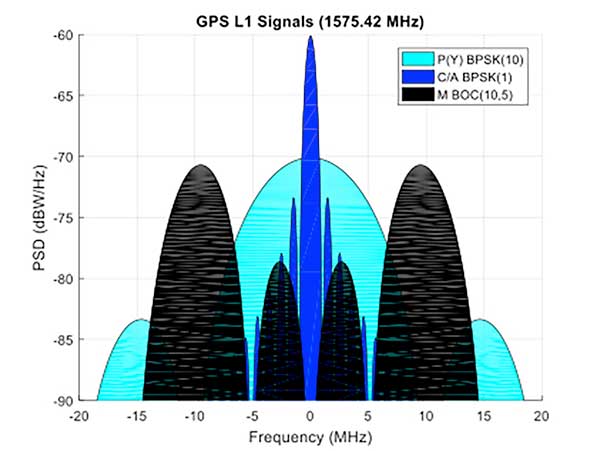
Until now, the military has used the classic P(Y) signal: a binary phase shift keying (BPSK)-modulated encrypted wideband signal. It offers both greater accuracy and increased jamming resistance when compared to the civilian C/A code still employed by the vast majority of GPS receivers.
But the P(Y) code has its drawbacks in the modern world: its wide main lobe sits directly over the top of the C/A code signal (see Figure 1), essentially occupying the same spectrum. When the civilian C/A signal is jammed, the military P(Y) signal is at the very least degraded, if not also jammed itself. It also uses a relatively simple encryption scheme that does not meet today’s cyber security requirements.
Figure 1. C/A, P(Y), and M-Code signal power spectra. (Graphics: Mike Jones)
The M-code signal, on the other hand, is the first military GPS signal to use the BOC modulation scheme. BOC modulation gives signals their distinctive two-lobe appearance, spreading the signal’s energy away from the band center.
The wide spacing of the two sidebands separates the M-code signal from the civilian signals (the legacy C/A signal or the new L1C signal on the L1 frequency, and the L2C signal on the L2 frequency).
Amongst other things, this allows the military to jam the civilian codes without noticeably degrading the M-code signal. Often referred to as blue force electronic attack (BFEA), this is essentially a new facet to navigation warfare (NAVWAR), where enemy use of GPS can be denied whilst allowing friendly forces to continue using it.
The wider occupied bandwidth and increased signal power also help to make M-code more resistant to jamming. M-code also makes use of more modern and flexible encryption methods, ensuring it will be secure and safer from threats such as spoofing attacks.
Scepticism. Defense programs are known for their long procurement cycles, but even by these standards, M-code has taken an extremely long time to get where it is today. Given the enormous cost of the program, and the fact that there is still, as yet, no operational benefit to show from it, many people have questioned its worth. At the time it was conceived it represented a dramatic step forward in military capability but, because it has been so long in development, its operational benefit is becoming diluted.
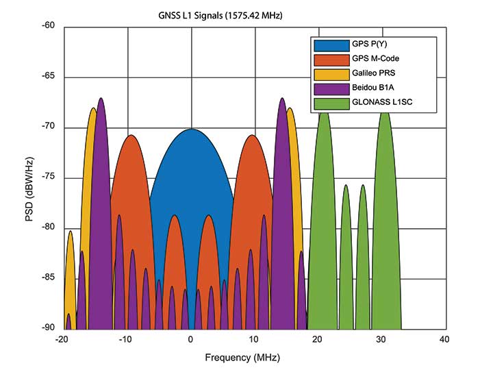
When M-code was conceived, GPS was still the only operational GNSS in town: everybody had to use GPS — or nothing. Today, the picture differs greatly. During M-code’s insanely slow progress, other GNSS systems have come along, offering their own encrypted signals of a similar ilk. Looking at Figure 2, M-code no longer appears as special as it once was. Its BOC(10,5) signal sits inside the main lobes of Europe’s Galileo PRS signal, which uses a BOC(15,2.5) scheme, and China’s Beidou B1A signal using BOC(14,2).
Figure 2. GNSS encrypted signals around the L1 frequency. (Graphics: Mike Jones)
If you were China, you might consider jamming the central 24 MHz of the L1 band, taking out M-code, whilst still having an operational military service for yourself. Or if you were Russia, you might jam 34 MHz of bandwidth, taking out the US, Chinese, and European systems, whilst still having your GLONASS L1SC military service to use. The situation is more complex than that, of course: each service has the potential to increase signal power in times of conflict, and there is more than one frequency that can be used. But it does demonstrate the essence of the problem: The modern battlespace has moved on, and M-code hasn’t.
CHALLENGES OF RECEIVER DESIGN
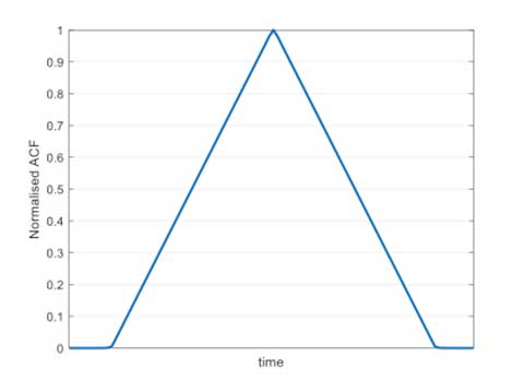
Figure 3. C/A code ACF.
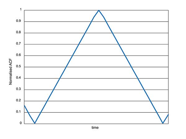
With complex signals come complex receivers, and there several headaches when it comes to M-code receiver design. The first is the nature of the BOC signal itself, which has a complex correlation function. Consider Figure 3, which shows the autocorrelation function (ACF) of the traditional civilian C/A code signal. The single peak of the function makes acquisition and tracking a simple process; traditionally early, prompt and late (E,P,L) correlator arms can be used in the tracking process.
Figure 4. L1Cd ACF.
The newer BOC-type signals have a more complex ACF. Figure 4 shows the ACF of the new L1Cd civilian GPS signal, which uses a form of BOS(1,1) modulation. In addition to the main lobe, there are now two side lobes. Receivers must be careful not to lock on to one of the side lobes instead of the main lobe: the receiver architecture starts to become a little more complex.
Figure 5. M-code ACF.
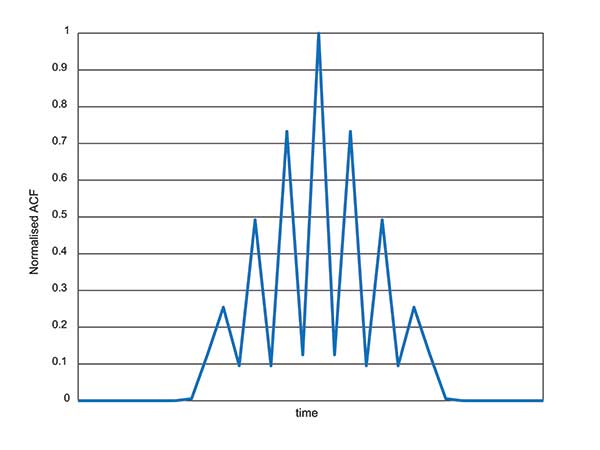
Now consider the ACF of the M-code signal, shown in Figure 5. Like other high-order BOC-type signals, M-code exhibits multiple lobes in the ACF, making robust acquisition and tracking a far more troublesome process. Furthermore, the high bandwidths require high sample rates, which lead to higher power consumption in the hardware.
Another major headache associated with M-code receivers is, of course, the encryption process. Not because encryption is difficult, but again because of the power consumption implications. Consider that each GPS receiver needs to run an encryption engine instance, for each satellite it might wish to receive. Running a high-grade encryption algorithm at a high chipping rate, for a dozen satellites, is a power-consuming process. For dismounted soldiers with limited battery capacity, this is a big deal.
Some people argue that the high-grade encryption process for M-code is too complex. Consider why we want to encrypt a GNSS signal in the first place: firstly to prevent someone from spoofing our signal, and secondly to prevent unauthorised users from using the service. Given that the encryption keys are rolled regularly, how much does it matter if an adversary manages to compromise the encryption? This isn’t a communications security problem: we are not talking about loss of classified information, so there’s an argument that a simpler, less power-hungry form of encryption might have been used instead.
ANTI-JAM ANTENNA COMPATIBILITY
Although M-code offers a certain level of jamming resistance, it is still vulnerable to attacks. As a signal it might have a bit more power, and a bit more bandwidth, than some other signals. But it is, after all, still a GNSS signal, and it can be jammed by an adversary. Where an operational threat analysis indicates that an increased level of jamming resistance is required, then M-code receivers need to be integrated with anti-jam antennas.
Anti-jam antennas, usually referred to in the GNSS community as controlled reception pattern antennas (CRPAs), have been the anti-jam tool of choice for several decades now. I overviewed these in an April 2017 newsletter column. CRPA manufacturers have had to ensure that their products are “M-code ready,” such that they can be seamlessly attached to M-code receivers as and when they appear.
This hasn’t been a recent process: as far back as 2002, the GAS-1 antenna (Raytheon) underwent a series of qualification tests to ensure compliance with M-code. Around 2005, the ADAP antenna (also Raytheon) was launched with a host of M-code features — again an illustration of just how slow the M-code program has moved, given that other technology has been “M-code ready” for 10 or 15 years already.
What’s involved in making a CRPA M-code compatible? Firstly the increased bandwidth: the antenna electronics must digitize the wider bandwidths. Along with the wider bandwidth comes new filtering shapes to ensure optimum performance.
Space-time adaptive processing (STAP) and space-frequency adaptive processing (SFAP) techniques potentially require more taps to ensure high null depths can be maintained across the full bandwidth. The increased power of the M-code signal, particularly if features like spot beam are used, presents another complication to CRPAs: they must not treat the high-power satellite signals as jammers, and try to remove them.
Testing CRPAs presents a challenge to manufacturers: how do you prove that your antenna doesn’t corrupt the M-code signal, when there’s no M-code signal to test it with? To work around this issue, pseudo M-code signals have been used for testing, where representative BOC(10,5) signals without the real encryption are passed through the CRPA and examined for distortion.
RECEIVER DEVELOPMENT STATUS
Due to the security considerations surrounding M-code, only three US organizations are authorized to produce modules: Collins Aerospace, Raytheon and L3. Here are the answers from Collins Aerospace and L3, the answers from Raytheon will appear in later issue.
What are the technical challenges associated with developing an M-code receiver?
Collins Aerospace. The Collins Aerospace Modernized GPS User Equipment (MGUE) Increment 1 development like the SAASM PPS receiver developments faced very challenging technical requirements to support our war fighter needs in an ever-evolving threat environment. Like other complex developments the challenges are initially technical and then transition to integration/test and certification. On the technical front optimizing receiver performance balanced against power consumption are always at the forefront. In addition, it is important to maximize backwards compatibility so as to minimize downstream integration costs while adding an entirely new signal that runs in parallel to the existing system. Collins Aerospace is pleased with the technical development and are actively supporting the integration with both receivers and technical support.
To date, we have delivered more than 770 MGUE receivers to the Air Force to support Air Force, lead platform and DoD-wide Integration and test. Soon the total will grow to nearly 1,100 receivers to support expanded integration and test following the completion of Collins Aerospace security certification.
L3. M-code GPS User Equipment (MGUE) technologies exist today.L3’s Ground Based GPS Receiver Application Module – Modernized (GB-GRAM-M) is a fully-functioning unit that is currently baselined and undergoing an independent Technical Requirements Verification (TRV) by the GPS Directorate.During TRV, each requirement from the Technical Requirements Document (TRD) is independently evaluated for compliance. Upon completion of the TRV, the design is baselined with complete documentation enabling platforms and prime equipment to integrate from a known baseline with low risk. Following integration, operational testing can start immediately to support fielding when M-Code Early Use (MCEU) becomes operational. The TRV of L3’s GB-GRAM-M is planned to be completed by the second quarter of 2019.
L3 resolved numerous technical challenges in developing M-code GPS technologies. The first and ever-present challenge is changing and evolving requirements. Most of these requirement changes are in response to evolving threats that have driven changes into the GPS receiver and/or to higher-level systems. Asan example, the U.S. Army’s Assured PNT (A-PNT) is implementing M- code GPS along with external sensors to establish and maintain an assured solution even in GPS-challenged environments. Other challenging requirements include meeting the security requirements, implementing and testing anti-spoofing algorithms, and ensuring backward compatibility with legacy receivers.
What are the intended platforms for your MGUE?
Collins Aerospace. The Collins Aerospace MGUE receivers are intended to support all warfighter domains: ground, airborne, maritime and munitions to support compliance with Public Law 111-383 SEC. 913 issued in Fiscal Year 2011. Per this directive, M-code is intended for all DoD applications with the exception of passenger vehicles or commercial vehicles with GPS installed. Now that the satellite and control segments of the capability are coming on line, we are working diligently to ensure that user equipment is available for all domains.
L3. L3 has products to meet current market demand. Under the MGUE program, L3 developed a GB-GRAM-M, which is a standard Modular Open Systems Architecture (MOSA) design. The GB-GRAM-M is designed to fulfill retrofit replacements of SAASM receivers, as well as being a primary component of A-PNT systems. L3’s M2GRAM ASIC is the core of our receiver, a GPS module that incorporates signal processing, cryptography, and positioning, velocity, and timing (PVT) processing. The M2GRAM ASIC is capable of being implemented in other form factors for applications beyond ground-based applications. As an example, the M2GRAM is implemented in a GPS receiver specifically designed for Precision Guided Munitions (PGM) applications and was used in a gun launched, guide-to-target demonstration operating as a PGM receiver.
L3 is also augmenting the GPS receiver through the integration of several other technologies, including controlled reception pattern antennas with digital antenna electronics, inertial systems and external sensors, and GPS-denied capabilities. M-code technologies are being implemented in Mounted A-PNT Systems (MAPS), Dismounted A-PNT Systems (DAPS), and handheld systems to bring capabilities to the warfighter.
What is the expected timeline for your MGUE development, acceptance testing, and delivery?
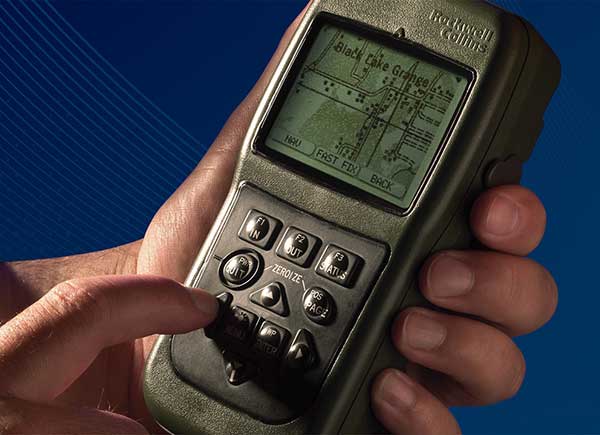
Defense Advanced GPs Receiver (DAGR) from Collins Aerospace, equipping infantry and other warfighters. (Photo: Collins Aerospace)
Collins Aerospace. The Collins Aerospace receivers are supporting ongoing DoD integration and test and our MGUE Increment 1 program is aligned with the Air Force GPS Enterprise roadmap. Ultimately, the Department of Defense (DoD) M-code programs will set the production delivery schedules.
We anticipate that the M-code production ramp-up and continued SAASM PPS receiver production will have a production overlap. Our Collins Aerospace in-house PPS GPS receiver manufacturing capability is ready to support the DoD demand for both M-code and SAASM. Collins Aerospace is fully committed to manufacturing Increment 1 M-code receivers to meet the warfighter’s needs across Airborne, Weapons and Ground, we know the transition from SAASM to M-code will take years. Therefore, Collins Aerospace will continue to manufacture SAASM receivers for years to come as the International MOD Policy for M-code use is still being formulated.
L3. L3’s GB-GRAM-M is now available. L3 received security certification and approval in 2016 and TRV is planned for completion in the second quarter of 2019. With TRV, L3 is receiving a new security certification and approval of the latest receiver update. Government agencies, prime contractors and laboratories can order GB-GRAM-M now with delivery in the fourth quarter of 2019.
What does testing and verification process involve?
Collins Aerospace. As with any Precise Positioning Service (PPS) GPS development, the testing involves functional verification of the receiver in a wide variety challenging of environmental, thermal, electromagnetic interference/ high-intensity radiated field (EMI/HIRF) environments. Collins Aerospace is leveraging proven test and verification approaches founded upon our long history of successful product introductions and field performance. As this is a PPS receiver it is also essential the receiver design comply with the government’s required Security Approval process.
L3. The testing and verification of L3’s GB-GRAM-M included internal testing and independent testing through the GPS Directorate’s TRV process. Further risk reduction testing within the MGUE program is planned as Phase IV testing where the GB-GRAM-M is integrated into a lead platform for the U.S. Army and a lead platform for the U. S. Marine Corps. An operational assessment is performed on both lead platforms to assure common problems associated with integration and operational testing are addressed prior to implementing M-Code GPS Receivers across all of the platforms.
Will the MGUE be compatible with CRPA anti-jam antennas; are there any special considerations for this?
Collins Aerospace. The Collins Aerospace product family includes our Digital Integrated Anti Jam Receiver (DIGAR) product family that leverages CRPA anti-jam antennas for enhanced anti-jam (AJ) performance. Our DIGAR AJ technology enhances the performance with fixed reception pattern antenna (FRPA), CRPA and is compatible with all PPS waveforms. Regarding the interfaces between the receiver and the anti-jam antenna electronics, a GPS receiver with a standard RF interface is compatible with a CRPA in nulling mode and FRPA antennas. Advanced capabilities such as beamforming/beamsteering require tight coordination and additional interface with the GPS receiver.
L3. The GB-GRAM-M is designed to operate with a fixed reception pattern antenna (FRPA). A CRPA antenna using digital antenna electronics to generate signals matching the characteristics of a FRPA is fully compatible with the GB-GRAM-M. With a higher level of integration of a GPS receiver and a CRPA, the system capabilities are greatly enhanced. L3 has performed this integration and can perform advanced capabilities such as angle of arrival and beamforming using M2GRAM, digital antenna electronics, and CRPA technologies. These capabilities can be found in L3’s Mounted Assured PNT System (MAPS) and Anti-Jam Antenna System (AJAS) products.
Army Stryker ground combat vehicle. (Photo: Karolis Kavolelis / Shutterstock.com)
OPERATIONAL DEPLOYMENT
The U.S. Air Force GPS Directorate provided answers to the following questions regarding MGUE.
Which platforms will be equipped with M-code-capable MGUE, and how many of each?
GPS Directorate. The Air Force is developing M-code-capable GPS receivers under the MGUE Increment 1 program. The receivers in development will be provided to four service-specific lead platforms for integration, developmental, and operational testing. Lead platforms are:
the Army Stryker ground combat vehicle,
the Air Force B-2 Spirit bomber,
the Marine Corps Joint Light Tactical Vehicle (JLTV),
and the Navy Arleigh-Burke class destroyer (DDG).
Following the lead platform efforts, procurement of M-code-capable GPS receivers will be decided by the Services and executed by individual platforms and programs.
What are the timelines for rolling out M-code on these platforms?
GPS Directorate. Early integration and test activities have already begun for each MGUE lead platform. Operational testing is expected to begin in 2020 and complete in 2021, which is a key activity to enable the fielding of M-code-capable systems.
B-2 Spirit multi-role bomber capable of delivering both conventional and nuclear munitions. In December 2017, the Air Force completed a series of successful flight tests of M-code GPS using a Raytheon Company receiver on board a B-2 Spirit at Edwards Air Force Base, California. (Photo: U.S. Air Force/Bobby Garcia)
What advantages will M-code bring, over existing military GPS receivers?
GPS Directorate. Modernized GPS receiver cards under development with the Air Force MGUE Increment 1 program will enable the use of M-code and provide U.S. forces with enhanced position, navigation, and timing capabilities, in addition to improving resistance to threats, such as jamming efforts by adversaries.
How will keys and key distribution be managed?
GPS Directorate. None of this is publically releasable.
Will M-code be made available to other friendly nations? If so, how is this managed?
GPS Directorate. The current policy allows for the sale of M-code equipment to all 57 authorized GPS PPS nations. The M-code technology will be made available to these nations through the Foreign Military Sales process.
USER PERSPECTIVE
The Department of Defense supplied answers to the following questions for users and warfighters.
What are the benefits you perceive will come from new M-code GPS equipment?
DoD. Provides U.S. forces with enhanced position, navigation, and timing capabilities, in addition to improving resistance to threats, such as jamming efforts by adversaries.
Will it change how you perform military operations, or enable any new ones?
DoD. Modernized GPS receivers provide the next-generation GPS capabilities to the warfighter. Operational testing will enable the services to determine operational utility of MGUE. It will ensure our soldiers, sailors, airmen, and marines have the ability to get in, accomplish their mission, and get home accurately.
How will M-code-based GPS receivers be brought into operational service? Will there be a mass upgrade of assets, or a phased introduction?
DoD. Procurement of M-code-capable GPS receivers will be decided by the Services and executed by individual platforms and programs.
Belgium has launched its first smart highway test environment. Septentrio GPS/GNSS receivers are integrated into vehicles and infrastructure to provide dependable, high-accuracy positioning and to aid sensor fusion in driverless navigation and truck platooning.
Septentrio’s high-precision GPS/GNSS technology will be one of the key components in a Smart Highway system, which launched April 8 with a live demonstration in Antwerp, Belgium. A section of a highway will be dedicated as a test environment for technology which prepares Belgium for automated driving and truck platooning.
When vehicles are aware of each other’s position and velocity, road efficiency and safety can be significantly improved by smoothing traffic flow and automatically breaking if slowing traffic is detected ahead.
Roadside units along the highway will feature GNSS receivers acting as reference stations, sending out continuous positioning corrections. Onboard GNSS units will use these corrections together with built-in quality indicators to calculate trustworthy, sub-decimeter positioning. They will also provide precise timing for syncing the multitude of sensors onboard these “smart vehicles.”
“We are excited to be a part of the Smart Highway testbed which is aimed at improving road safety and traffic flow,” said Jan Van Hees, business development director at Septentrio. “The automotive ecosystem is undergoing a shift towards automation enabled by the latest technology in communications, sensors and precise positioning. Our role in this project builds upon our strategy to continue providing high-accuracy, reliable positioning solutions aimed at the automotive industry.”
The Advanced Interference Mitigation (AIM+) technology shields Septentrio receivers from interference. On a highway, an increasing number of trucks are equipped with illegal jamming devices to avoid road tolling. These jamming devices can interfere with GPS signals used by other vehicles and infrastructure.
Smart Highway is a project of the Flemish government coordinated by imec, a world-renowned research and innovation hub of nano-electronics and digital technology. Septentrio, Toyota, Ericsson and Telenet are contributing industry partners for the project, while UAntwerpen, UGent and others are research partners.
On the European level, the CONCORDA project supports research and development of automated vehicle technology and infrastructure in Germany, Spain, France, Netherlands and Belgium.
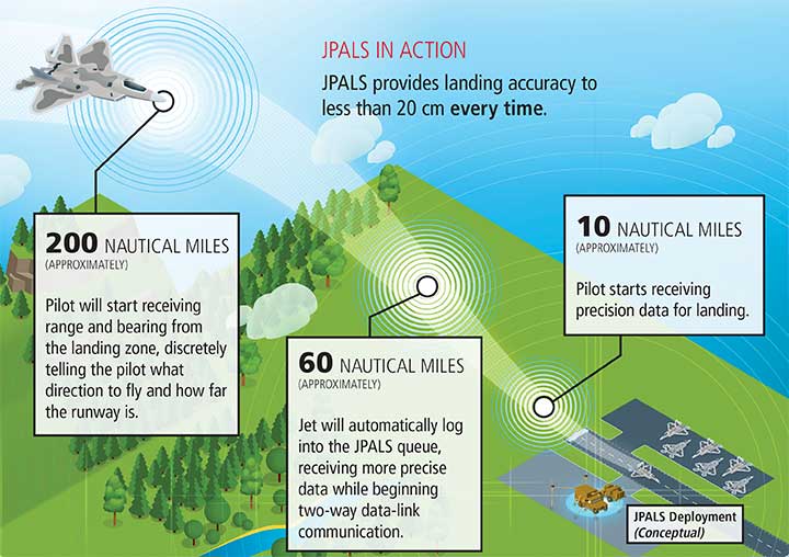
Earlier this year, Raytheon Company demonstrated a land-based expeditionary version of its Joint Precision Approach and Landing System (JPALS) for the first time to U.S. Air Force, Navy and Marine Corps officials at Marine Corps Air Station, Yuma, Arizona.
During the demonstration, F-35B pilots used the JPALS system on the jet to connect with the expeditionary system on the ground from 200 nautical miles away. From there, the system guided the pilot to a designated landing point on the runway.
“The need for precision landings in harsh environments isn’t limited to one military service and one airplane,” said Matt Gilligan, vice president at Raytheon’s Intelligence, Information and Services business. “JPALS can help any fixed or rotary-wing aircraft land in rugged, low-visibility environments at austere bases worldwide.”
The proof-of-concept event showed how the GPS-based system, which is currently used to guide F-35Bs onto ships in all weather, could be reconfigured into a mobile version to support landings in a traditional airport setting.
Infographic: Raytheon
Expeditionary JPALS supports the U.S. Air Force’s desire to use more austere, bare-base locations for future flying operations.
Currently in five transit cases, it could be repackaged for a variety of small transit vehicles transportable by C-130. Once on the ground, the system can be fully operational in under 90 minutes.
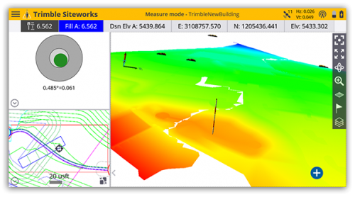
Trimble has introduced Siteworks Software version 1.1, featuring full GNSS tilt compensation functionality in standing, walking and vehicle modes, and support for the Android operating system.
Construction surveyors can now capture accurate points without leveling the pole, making surveying in areas such as building corners accurate, fast and easy.
In addition, Siteworks version 1.1 now supports the Android operating system, giving contractors the flexibility to choose the field device that best fits their needs and budget.
The announcement was made at the bauma 2019 trade fair for construction machinery, building material machines, mining machines, construction vehicles and construction equipment. Bauma 2019 takes place this week in Munich.
“GNSS tilt compensation makes site positioning more accessible and easier to learn for beginners, while experienced surveyors can see significant time savings,” said Scott Crozier, general manager for Trimble’s Civil Engineering and Construction Division. “And now Trimble Siteworks gives contractors more choices. They can run Siteworks on either Windows 10 or Android.”
GNSS Tilt Compensation
Using Trimble Siteworks and a Trimble SPS986 GNSS smart antenna, construction surveyors can take measurements faster and perform more efficient stakeouts.
The solution was designed to shield magnetic interference, and it can be used effectively anywhere on a construction site.
There are three modes available that support tilt compensation, so contractors can record accurate points while standing, walking or driving the site in a vehicle. Tilt compensation in vehicle mode is designed to capture higher accuracy measurements on steeper slopes from a moving vehicle, and more accurate volume measurements to save time and money on material planning.
Easy to use for beginners and users without traditional training, tilt compensation allows points to be recorded more safely, eliminating the need to stand in the road to measure a traffic lane, for example. Surveyors can also measure points that they couldn’t before, such as building corners, edges of trenches and utility flowlines.
Trimble Siteworks for Android
Trimble Siteworks can now support a contractor’s bring-your-own-device (BYOD) strategy with Android compatibility. This is helpful for price-conscious users such as owner operators and utility contractors, or users who need a less rugged solution for lighter use.
The option gives contractors the freedom to choose the device that works best for them, increasing the flexibility and affordability of the Trimble Siteworks Positioning System.
Availability
Trimble Siteworks Software version 1.1 is expected to be available through the worldwide SITECH distribution channel in the second quarter of 2019.
Hemisphere GNSS introduced its GradeMetrix platform, a machine guidance solution for high-precision GNSS-based machine control and guidance applications and systems, at bauma 2019.
GradeMetrix positioning systems — as well as the new Earthworks OEM solution toolkit — will be featured in the Hemisphere stand (A2.228) at bauma 2019 in Munich, Germany, April 8-14. Bauma 2019 is a construction machinery trade show.
GradeMetrix
Hemisphere’s GradeMetrix portfolio includes solution offerings for dozer and excavator earth-moving applications. Hemisphere continues to make significant strides forward with its next-generation GradeMetrix solutions through its network of machine control dealers and value-added resellers (VAR). Whether it is grading, mining, excavating, or compaction applications, GradeMetrix solutions provide superior performance at an exceptional value.
“GradeMetrix and Earthworks OEM platforms and design services empower dealers, VARs, and original equipment manufacturer (OEM) customers with unparalleled flexibility and price points for designing, complementing, and delivering their own scalable solutions,” said Randy Noland, vice president of global sales and business development at Hemisphere. “These offerings deliver a new generation of positioning systems by removing multiple barriers to entry and higher adoption rates, especially to smaller customers, machines, and markets.”
Earthworks OEM toolkit
Hemisphere also announced its Earthworks OEM toolkit ,which allows manufacturers to select components as à la carte or complete solutions, based on their accuracy and durability requirements to integrate into their machines and design their own IP, enabling them to maintain a competitive advantage in the marketplace.
The customizable and flexible toolkit provides the ability to tailor displays and outputs, per their requirements, providing OEMs with flexible options to build their own branded systems. This allows for much faster times to market, driving increased revenue streams for OEMs, and provides a high cost/value ratio. From grading, to mining, to excavation, Hemisphere’s Earthworks OEM toolkit increases accuracy, efficiency and profitability.
Speeding time to market and customer
In the increasingly competitive OEM marketplace, manufacturers are scrambling to get positioning and other non-native technologies out to market on their machines. As the uptake of this technology becomes more mainstream with the customer base, each OEM, VAR and even super distributor are all racing to define a profitable system design they can deploy through their own channels.
With the release of GradeMetrix and Earthworks OEM product lines, Hemisphere is addressing this demand. Typical development times for OEMs with vendors for positioning systems is measured in years, not months. With these new product lines, Hemisphere is providing a new avenue for these customers to get their own system established and into the marketplace, much faster and with lower development costs.
Spirent Federal Systems, a provider of GPS/GNSS test equipment, announced that Col. (retired) Bernard Gruber, former program director of what is now the U.S. Air Force GPS Directorate, has joined the company’s board of directors as government security committee chairman. Also joining as the chairman of the board is Robert Lollini.
Spirent Federal President/CEO Ellen Hall stated, “We are happy to have retired Col. Gruber and Bob Lollini joining our dynamic company. We are leading the industry in innovation and quality products for the U.S. government and these two new leaders will help us continue that momentum.”
Col. Bernie Gruber in 2012. (Photo: U.S. Air Force)
Bernard Gruber brings to the position the experience gained from a long and distinguished career in the government and military sector. Mr. Gruber has held several positions in important commands focused on navigation in space, including serving as the chief of Space and Global Integrated Intelligence at the Pentagon from 2009-2010, and director of the Global Positioning System (GPS) at the Los Angeles Air Force Base from 2010-2013. He is currently the director of Precision Guidance and Advanced Programs, Armament Systems at Northrop Grumman.
Robert Lollini is currently the chief executive officer and president of BioFire Defense LLC, a subsidiary and proxy company of bioMerieux. Lollini contributes to the board his broad understanding of strategic financial and executive management.
Spirent Federal Systems was formed in July 2001 by Spirent Communications as a wholly owned subsidiary and U.S. proxy company. Spirent Federal markets and sells Spirent Communications’ GNSS products in North America. The company also provides value-added features and ongoing customer support. Spirent Federal Systems is headquartered in Pleasant Grove, Utah, with support and sales offices throughout the U.S.