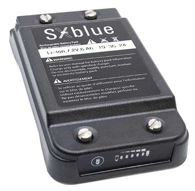
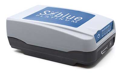
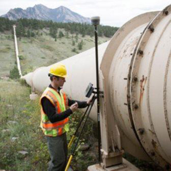
Geneq inc. has released a redesigned, ultra-efficient battery for its SXblue receivers.
The new battery is equipped with 4 Li-ion rechargeable cells that boost its capacity from 3900 mAh to 6000 mAh. The upgrade boosts the receiver’s autonomy by up to 50 percent, greatly increasing its field work efficiency, the company said.
When fully charged, the battery can last up to 16 hours depending on the SXblue model and Bluetooth connectivity.
Photo: Geneq
The colored LEDs for the battery charge indicator have been enhanced for a better contrast even when working under sunny conditions. Like previous versions, the new battery is field replaceable and can be charged separately or while it is connected to the receiver. With only a 6-mm increase in thickness and the same weight as previous models, the user will not notice any change in handiness and ergonomics, Geneq added.
The new battery is compatible with all past SXblue II and III models and current iSXblue II+ GPS, SXblue II+ GPS, iSXblue II+ GNSS, SXblue II+ GNSS and SXblue Platinum. It is also compatible with the new pole clamp accessory for the survey kit.
Orolia has successfully installed the first operational Cospas-Sarsat second-generation technology on search-and-rescue ground stations for the National Oceanographic and Atmospheric Administration (NOAA) in Florida and Hawaii.
The ground stations have been upgraded with second-generation beacon (SGB) signal-processing capabilities to more accurately and quickly locate the source of distress signals.
The NOAA Florida and Hawaii ground stations are the only operationally ready Medium Earth Orbit Search and Rescue (MEOSAR) ground stations in the world to receive the SGB signal specification capability.
The Cospas-Sarsat global search-and-rescue system developed specifications for the second-generation 406-MHz search-and-rescue beacon, which uses a modern, spread-spectrum signal to achieve more accurate and robust performance.
“The work performed by Orolia was exceptional, as the process of upgrading an operational system to a higher set of requirements, years after its initial design, involves minimizing downtime while validating the new requirements and revalidating the previous requirements,” said Mickey Fitzmaurice, NOAA SARSAT Systems Engineer. “The successful result makes it obvious that the engineering and operations team at Orolia put a great deal of time and effort into planning the upgrade, as the execution was seamless.”
“This series of world firsts demonstrates Orolia’s broad technical leadership in the global search and rescue ecosystem,” said Orolia Director of SARSAT Operations, Steve Ludwig. “We continually innovate to enhance the usefulness of these technologies, from generating encrypted beacon alert signals to including alert authentication through the use of Galileo Return Link Service.”
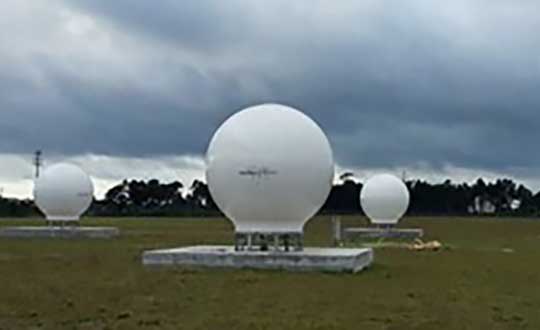
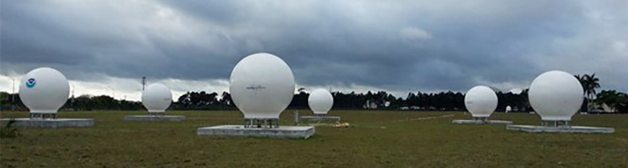
Cospas-Sarsat ground stations are called Local User Terminals (LUTs). These satellite receiving units are the ground stations that receive emergency beacon distress alerts. (Photo: NOAA)
Portlandia Prediction: Fred Armisen and Carrie Brownstein have a few questions about their chicken dinner. (Screenshot: IFC)
In 2011, the first-ever episode of a TV comedy called “Portlandia” debuted. In one sketch, concerned diners played by series stars Fred Armisen and Carrie Brownstein question their waitress about the origins of their chicken dinner.
The waitress shows the couple the chicken’s papers and photo — Colin the Chicken lived a free-range life on a four-acre woodland farm only 30 miles away, dining on sheep’s milk, soy and hazelnuts, in the company of his chicken friends. Unconvinced even by these details, the couple decides to drive to the farm to see it for themselves.
Enter GoGo Chicken
In a case of comedy becoming reality, Chinese insurance company ZhongAn Online has outfitted more than a 100,000 chickens with GPS trackers. People who buy a chicken with a tracker strapped to its leg will know every step that that chicken has taken. Using a smartphone app called GoGo Chicken, customers can monitor the animal’s diet, exercise and environment.
The company says its technology will be on 2,500 farms in China by next year. It is also working on facial-recognition technology so that consumers can make sure the organic chicken they saw on the farm is the same one that ends up on their plate.
While this all sounds a bit much for many of us who grew up on Chicken McNuggets, there is a practical side. The company hopes GPS tracking will help prevent food safety problems, such as a 2014 crisis in China in which a supplier was caught selling rotting and expired meats to fast-food chains. In the event an issue does arise, the data tracked by the devices could help find the source of the problem.
An Arizona electric cooperative that serves more than 33,000 customers is helping prove the value and potential of unmanned aerial systems (UAS) in enhancing the utility’s geospatial information system (GIS) effort.
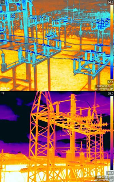
Using an Intel Falcon 8+ Drone — Topcon Edition, UAS specialist Skynetwest is performing missions to illustrate the viability of UAS technology. Initial work for the Navopache Electric Cooperative (NEC) included inspection of a substation, conducted on a windy day that might have grounded traditional aircraft.
Windspeed limits for the Falcon 8+ in GPS mode are set at 26 mph; in height mode that threshold is extended to windspeeds as high as 35 mph.
Using ContextCapture and Agisoft PhotoScan software, Skynetwest created a detailed georeferenced 3D model of the substation.
The Falcon 8+ also has triple-redundancy inertial measurement units (IMUs), double redundant compasses, dual-constellation GPS, eight propellers and two batteries. An algorithm selects the most accurate of the redundant systems to use when the UAS is flying near the electromagnetic frequencies emitted by power lines.
The team easily switched between a camera payload for inspections and one for mapping. Skynetwest’s mapping package takes high-resolution geo-referenced aerial images from various heights within set GPS tolerances. Its RGB camera delivers both orthophotos and 3D models in Topcon ContextCapture software, powered by Bentley Systems.
Autotalks, a V2X (vehicle-to-everything) communication company, is gaining momentum in the Chinese market following the successful completion of the C-V2X field test with a Chinese technology giant.
The field trial evidenced Autotalks’ C-V2X capabilities on a public road, including 3GPP release 15 compliant transmit diversity, and remarkable communication range of over 2 kilometers with a nominal range of over 1.5 kilometers.
As part of its momentum in China, Autotalks is growing its Chinese partner ecosystem and hiring for its operation in this giant market. Autotalks is a member of IMT-2020, CAICV and China ITS Industry Alliance, working on standardization and testing of C-V2X towards mass deployment. The company has also launched a Chinese website.
China is a fast-growing region in the automotive and intelligent transportation systems (ITS) segments. LTE-V2X technology has been gaining strong momentum in China. In November 2018, Autotalks announced that it has recruited Xiaobing Yang, to lead Autotalks’ business development efforts in China out of Autotalks’ new branch in Beijing. Yang brings to Autotalks more than 25 years of experience in the Chinese telecom industry.
In 2018, Autotalks launched a global V2X solution supporting both DSRC and LTE-V2X (also known as C-V2X) based on its second-generation mature chipset with the intention of expanding its global footprint into China. Autotalks’ LTE-V2X direct communications (PC5) solution is separated from the cellular Network Access Device (NAD), resulting in a secure and cost-effective standalone LTE-V2X solution.
Autotalks announced in February that it has partnered with MediaTek. a global fabless semiconductor company that enables 1.5 billion connected devices a year. The two companies are cooperating on integrating V2X and telematics and have completed a joint reference design for Telematics Control Unit (TCU) integrated with a global V2X chipset.
The reference design is based on Autotalks’ global V2X chipset and MediaTek’s newest technology, an automotive-grade cellular modem SoC, enabling a secure, robust and cost-effective global TCU architecture.
The WingtraOne vertical take-off and landing (VTOL) fixed-wing mapping drone now carries the RedEdge-MX multispectral sensor for vegetation mapping.
The WingtraOne is a VTOL drone that allows for flexible take-off and landing, with automated vertical take-off and landing even on gravel or in forest isles.
The WingtraOne provides wide coverage for comprehensive and high-quality multispectral image gathering, with coverage of up to 160 ha (395 ac) with 8.2 cm (3.2 in)/px GSD at 120 m/ 394 ft in one flight.
The Terrain Following feature provides for intuitive flight planning with fully automated functionality, the company said.
The RedEdge-MX features a patent-pending DLS 2 and a calibrated reflectance panel that enhances radiometric calibration and provides useful data for comparison of results over time, improving crop and stand monitoring.
The camera captures five narrow spectral bands: red, green, blue, near infrared and red edge. It generates plant health indexes and RGB (color) images from one flight, and is calibrated for precise, repeatable measurements.
Standard data outputs are compatible with almost all processing platforms.
Trimble has expanded its CenterPoint RTX Fast GNSS correction service coverage area in North America.
Additional states and provinces now covered by Trimble RTX Fast include Alabama, California, Florida, Georgia, Michigan, Mississippi, New Mexico, North Carolina, Ohio, Oregon, South Carolina and Washington, and Alberta and Ontario Canada.
Trimble RTX Fast reduces convergence time, allowing customers to achieve horizontal positioning accuracy of better than one inch (2 centimeters), in as fast as one minute.
Now, with CenterPoint RTX more farmers, surveyors, GIS professionals and construction contractors can experience the RTK-level accuracy of traditional cellular-based Virtual Reference Station (VRS) networks, while benefiting from the versatility of a satellite-delivered correction service, Trimble said.
“Trimble RTX technology has continually evolved since its launch in 2011 with improving accuracy and reduced convergence times,” said Patricia Boothe, vice president of Trimble’s Advanced Positioning Division. “This network expansion demonstrates our commitment to bringing the market-leading performance of Trimble RTX Fast to more users, in more geographies around the world.”
Trimble’s RTX network is currently available throughout most of the world, with the RTX-Fast network coverage available in select geographies in the U.S., Canada and throughout most of Europe, when using Trimble RTX compatible GNSS receivers. Subscriptions are available through Trimble’s Authorized Business Partners or Trimble’s online store.
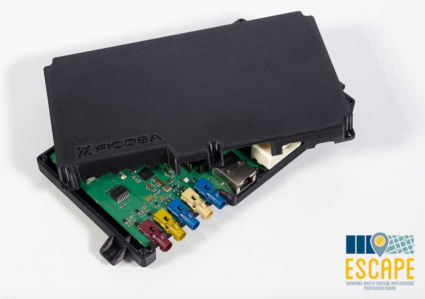
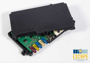
A European Union project has designed and prototyped the ESCAPE GNSS Engine (EGE), a positioning module intended to enable autonomous or semi-autonomous driving functions.
Automated vehicles are on the way, and the European GNSS Agency (GSA) sees satellite navigation as a core technology that will help to ensure their safe operation. At the recent Mobile World Congress in Barcelona, the GSA shared its space with the ESCAPE project, an EU-funded initiative that has developed a unique positioning module for autonomous or semi-autonomous driving.
Autonomous vehicles will feature both sensor-based and connection-based solutions for a variety of vehicle services. Ultimately, the GSA sees a “converged solution” as the best alternative, combining the strengths of both approaches. By integrating sensor data and connectivity-based information, operators can reduce the need for the most expensive sensors and at the same time save money on infrastructure.
The Fundamental Elements-funded ESCAPE project has designed and prototyped the ESCAPE GNSS Engine. It is a unique positioning module that combines precision GNSS and 4G connectivity, for the highly accurate and reliable positioning capabilities required to make automated driving a reality.
The ESCAPE GNSS Engine. (Photo: GSA)
“This is an onboard unit for autonomous vehicles,” said Jessica Garcia Soriano, R&D engineer of the Advanced Communications Business Unit at Ficosa. “It is equipped with a very good GNSS receiver made by STMicroelectronics. This was actually the first dual-frequency GNSS receiver made for the automotive market.”
Dual-frequency is of course a real differentiator for Galileo, as the world’s leading provider of dual-frequency GNSS signals. This means added precision and robustness and it helps enormously with multi-phase errors and other urban canyon issues in city-driving scenarios.
“We also have a very good positioning solution provided by GMV, another Spanish company. They are experts in these kinds of solutions. The outputs from this solution are very accurate. So we have GNSS of course, including Galileo, and apart from this you have a modem inside, a 4G modem that gets GNSS corrections from the internet, so this helps to provide better positioning. And apart from this you have inside the same module an inertial measurement unit [IMU]. This is a sensor, a device that senses acceleration and has a gyroscope, so this information also helps in providing good positioning.”
The ESCAPE unit also provides for the integration of other data from the vehicle. “That means vehicle odometry, for instance, you can have camera information, or information from maps that are stored in the vehicle, among others” Garcia said.
The market is ready
“One of our important goals is to provide a low-cost system,” Garcia said. “There are other very good positioning systems that are being developed that can be based on some very advanced technologies, such as LiDAR for instance, but this is very expensive. So our target is to develop and build a prototype of a system that could be installed in all vehicles, for the whole market. And so we are combining GNSS, 4G, IMU and all of these other data sources from the vehicle in an intelligent way, in an affordable way.”
Indeed, one of the things that make ESCAPE unique is the way it brings together high-end GNSS processing capabilities with an industrialisation process that targets high volumes and comparatively limited cost and size. It also encompasses hardware and software safety procedures required for certification for the automotive market.
Garcia explained, “At Ficosa, we are a top-tier global provider devoted to the research, development, manufacturing of vision, safety, connectivity and efficiency systems for the automotive sector. We provide solutions directly to vehicle manufacturers. Based on our expertise and thanks to the work we have done on this project, we understand very well that GNSS is a central focus for a lot of applications. From the moment we started working on this project, at Ficosa we realised that this is a new and very important market. Right now we are working on a positioning system for autonomous driving based on this unit. This is part of our roadmap at the moment. This is a positioning system that we are ready to offer to the customer.”
The unit is ready now, but we have yet to see autonomous cars in large numbers on the road. Is this a problem for the ESCAPE system? Garcia answered, “From the very first moment that you have an autonomous car in the street, you will need high-accuracy positioning, because these vehicles will need this positioning to maintain themselves safely on the road. But we don’t have to wait for autonomous cars. The vehicles on the road today can already benefit from this technology.”
Garcia pointed to Europe’s eCall system, where a call centre automatically receives location information from vehicles in distress, thanks to on-board GNSS. “You already have this emergency call technology in the vehicles,” Garcia said, “and it provides a location, so the better the location is, the easier it is to locate the people in an emergency situation. No, we don’t have to wait.”
Location and more
One thing everyone seems to agree on is that autonomous vehicles will soon be appearing on European road networks, and most driving-related decisions will be based, one way or another, on the location of the vehicle and of other vehicles and objects in its vicinity. So vehicle location and positioning will be a critical component for the effective transportation of people and goods by self-driving road vehicles. That positioning will be enabled mainly by GNSS technologies, including Europe’s Galileo, which is expected to offer significant benefits in terms of accuracy and authentication compared to the other satellite-based navigation systems.
GNSS-based location will have to be complemented by other technologies in order to get to the integrity level needed in all driving situations, but the GSA also believes the combination of dual-frequency GNSS and 4G/5G connectivity can do more than just navigation, enabling as well a diverse range of in-vehicle location-based services (LBS), much like what we see emerging in smartphones. The EU-funded ESCAPE project, with its innovative GNSS engine, represents an important step forward in the pursuit of accurate, reliable and affordable positioning and connectivity for the emerging autonomous and connected cars markets.
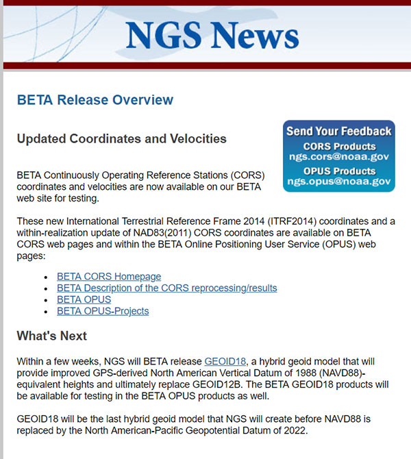
My last column discussed the preliminary results of NGS’ second Multi-Year CORS Beta Solution of the National CORS. Since my last column, NGS announced the release of the beta version of the hybrid geoid model GEOID18 and, on Feb. 15, NGS officially released the Beta CORS ITRF2014 coordinates and velocities.
This column provides the official links to NGS website that provide the beta coordinates and information about the latest multi-year CORS solution. Below is the NGS announcement of the beta release of the updated coordinates.
Excerpt from Feb. 15, 2019, “NOTICE: New BETA Coordinates Available for CORS and OPUS”. (Screenshot: NGS)
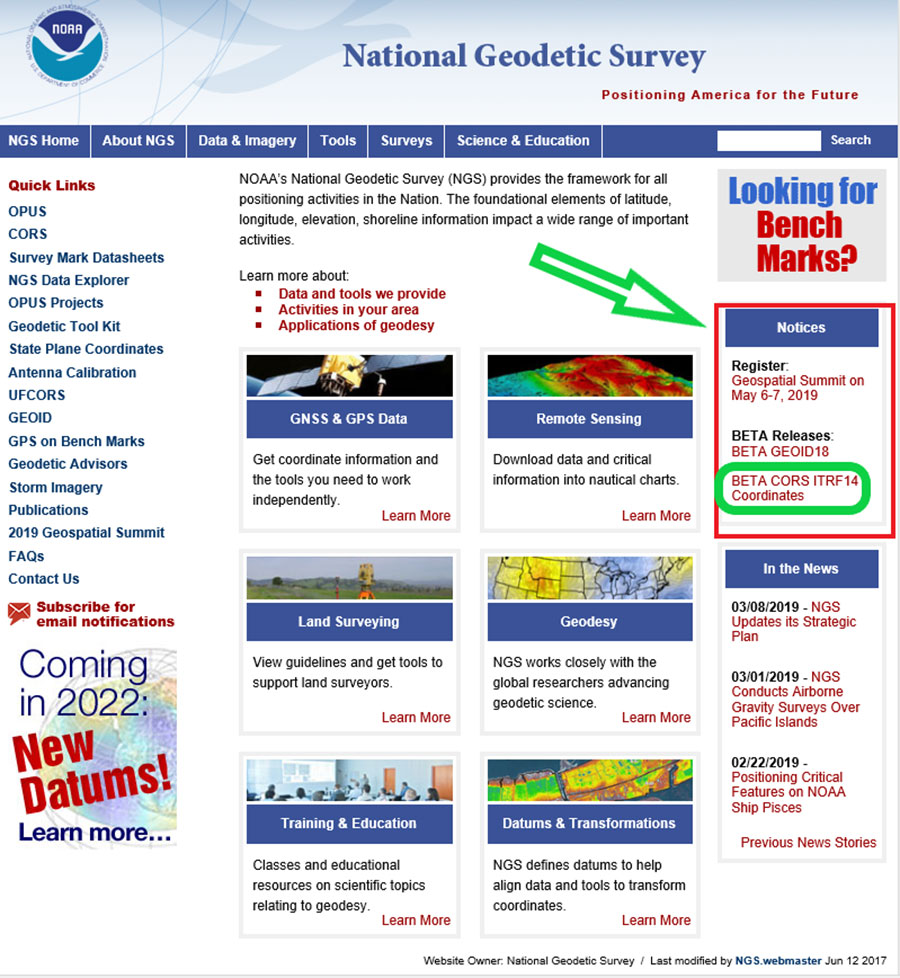
NGS also provides a notice of the new beta coordinates on the National Geodetic Survey homepage, with a link to the Beta CORS ITRF14 coordinates (see the highlighted section below).
National Geodetic Survey homepage. (Screenshot: NGS)
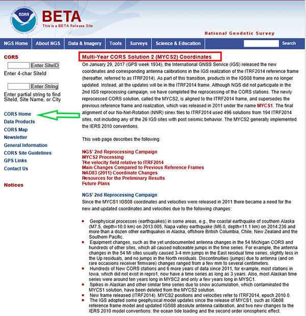
Information on Multi-Year CORS Solution 2. (Screenshot: NGS)
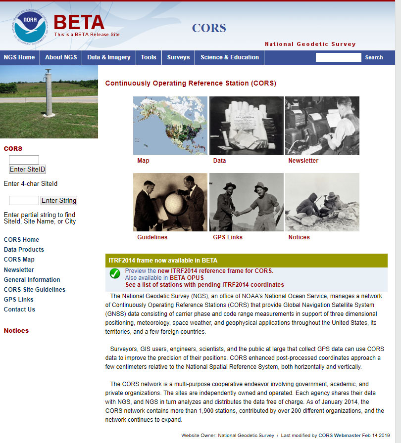
By clicking on the CORS Home button, the user is directed to the Beta CORS page.
Beta CORS release page. (Screenshot: NGS)
This page clearly states that the ITRF2014 reference frame for CORS is available as a beta product. It also implies that these coordinates are being used in other beta products such as OPUS. I’ll address this later in this column.
Users can obtain information about the MYCS and other related products and services such as Beta OPUS by clicking on links provided on the Beta CORS homepage.
Accessing information about ITRF2014 frame in NGS beta products. (Screenshot: NGA)
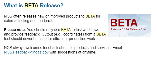
It should be noted that these values are considered “beta” and are available to users for testing and feedback. NGS provides a statement about its beta release products. Basically, it states that users should only use beta products to test their workflows and never for official or production work.
The NGS beta release statement. (Screenshot: NGS)
To facilitate testing of the beta CORS coordinates and velocities, NGS provides links to other beta products that will use the MYCS 2 coordinates and velocities.
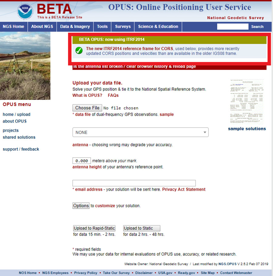
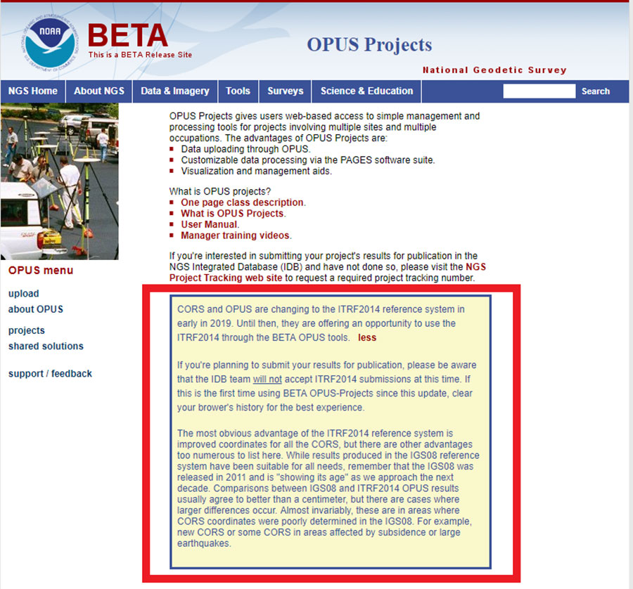
By clicking on the link labeled BETA OPUS on the beta CORS homepage, the user is directed to the BETA OPUS webpage. This page clearly states that the beta OPUS routine uses the new ITRF2014 reference frame for CORS.
Once again, the Beta OPUS Projects website clearly states that the beta version is using the CORS coordinates and velocities from the MYCS2. It also states that, at this time, NGS will not accept ITRF2014 submissions for publication. As previously stated, NGS’ beta products are for users to test their workflows and should never be used for official or production work.
The Beta CORS webpage provides a lot of valuable information on the processing and establishment of the multi-years CORS solution. I’ve highlighted several of the sections below.
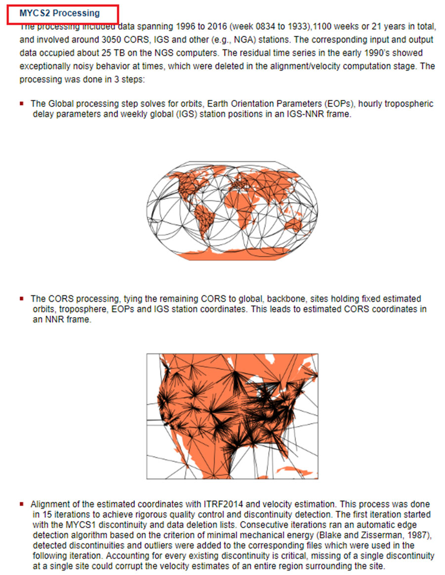
First, by clicking on the link MYCS2 Processing, the user is directed to the section that describes the data used and the processing strategy.
Excerpt from Beta CORS Webpage – MYCS2 Processing. (Screenshot: NGS)
The following are highlights from the section:
The processing included data spanning 1996 to 2016 and involved around 3050 CORS, IGS and other (e.g., NGA) stations.
The corresponding input and output data occupied about 25 TB on the NGS computers.
The residual time series in the early 1990s showed exceptionally noisy behavior at times, which were deleted in the alignment/velocity computation stage.
The processing was performed in 3 steps:
1. The global processing step solves for orbits, Earth Orientation Parameters (EOPs), hourly tropospheric delay parameters and weekly global (IGS) station positions in an IGS-NNR frame.
2. The CORS processing step ties the remaining CORS to global, backbone, sites holding fixed estimated orbits, troposphere, EOPs and IGS station coordinates. This leads to estimated CORS coordinates in a no net rotation (NNR) frame.
3. The last step is the alignment of the estimated coordinates with ITRF2014 and velocity estimation. This process was done in 15 iterations to achieve rigorous quality control and discontinuity detection.
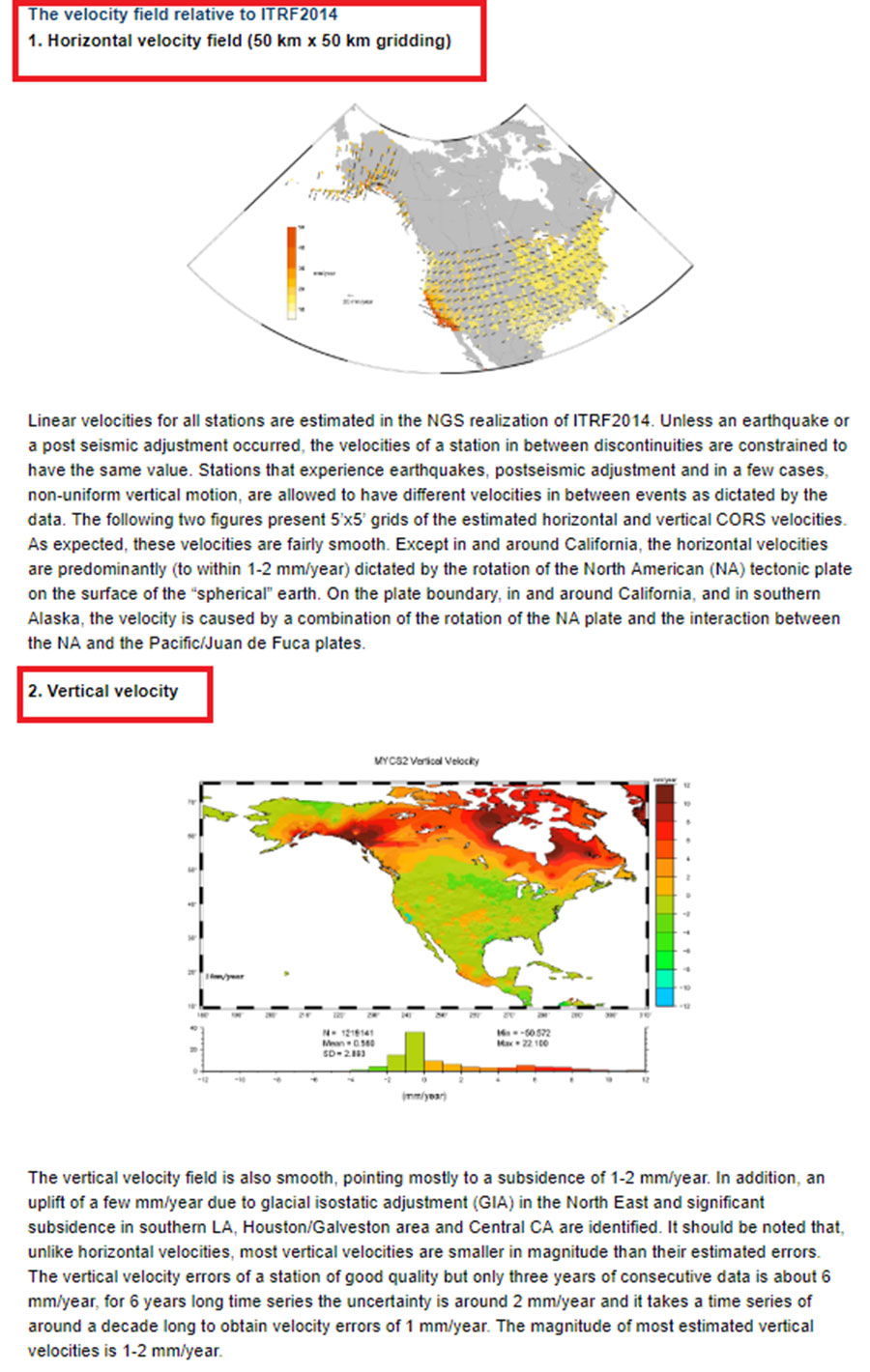
Linear velocities for all stations are estimated in the NGS realization of ITRF2014. NGS explains how this was implemented in the section titled “The velocity field relative to ITRF2014” (see box titled “Section Describing the Velocity Field Relative to ITRF2014”). The website provides figures that depict the horizontal and vertical velocities used in the processing.
The following are a few highlights from the section:
Unless an earthquake or a post seismic adjustment occurred, the velocities of a station in between discontinuities are constrained to have the same value.
Stations that experience earthquakes, post seismic adjustment and in a few cases, non-uniform vertical motion, are allowed to have different velocities in between events as dictated by the data.
The webpage provides figures that depict the estimated horizontal and vertical CORS velocities.
Section describing the velocity field relative to ITRF2014. (Screenshot: NGS)
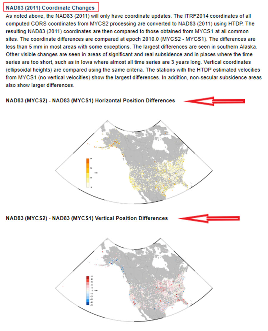
What users usually want to know is how much the coordinates have changed and what it means to their surveying activities. The section titled “Main Changes Compared to Previous Reference Frames” provides information and plots that depict the changes of coordinates.
Section on changes in coordinates. (Screenshot: NGS)
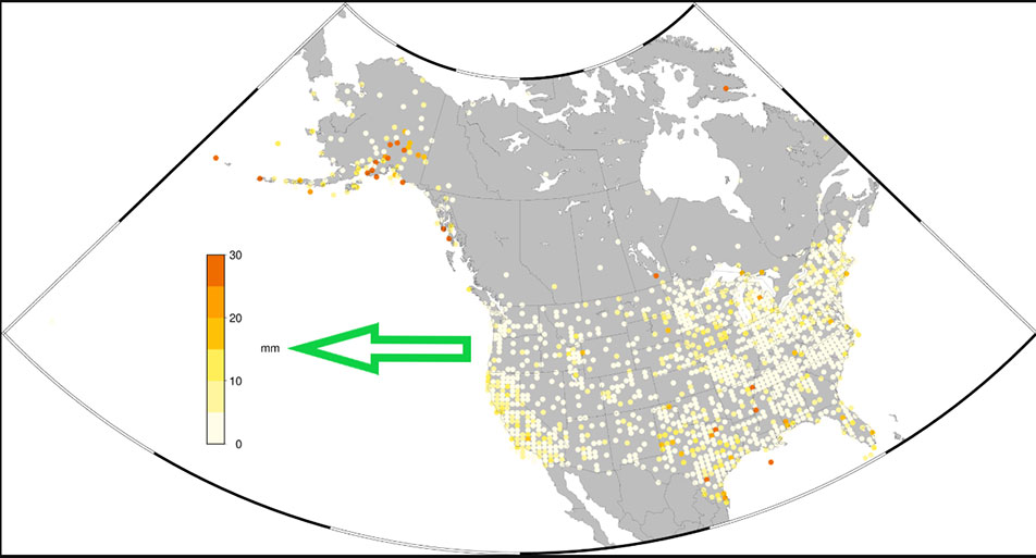
This section provides NAD83 (MYCS2) coordinate values minus NAD83 (MYCS1) coordinate values.
The following are a few highlights from the section:
The ITRF2014 coordinates of all computed CORS coordinates from MYCS2 processing are converted to NAD83 (2011) using HTDP.
The resulting NAD83 (2011) coordinates are then compared to those obtained from MYCS1 at all common sites.
The coordinate differences are compared at epoch 2010.0 (MYCS2 – MYCS1).
The differences are less than 5 mm in most areas with some exceptions.
The largest differences are seen in southern Alaska.
Other visible changes are seen in areas of significant and real subsidence and in places where the time series are too short, such as in Iowa where almost all time series are three years long.
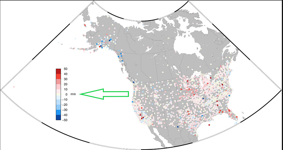
Vertical coordinates (ellipsoidal heights) are compared using the same criteria.
The stations with the HTDP estimated velocities from MYCS1 (no vertical velocities) show the largest differences. In addition, non-secular subsidence areas also show larger differences.
By clicking on the plots, the user is directed to a larger figure that is easier to interpret. (See boxes titled “NAD83 (MYCS2) – NAD83 (MYCS1) Horizontal Position Differences” and “NAD83 (MYCS2) – NAD83 (MYCS1) Vertical Position Differences.”)
NAD83 (MYCS2) – NAD83 (MYCS1) Horizontal Position Differences. (Screenshot: NGS)NAD83 (MYCS2) – NAD83 (MYCS1) Vertical Position Differences. (Screenshot: NGS)
NGS has done a tremendous job of explaining the MYCS2 process and results. As the results indicate, most differences between the MYCS1 and MYCS2 are small. Saying that, I would encourage all users to look at the NGS Beta webpages and obtain an understanding of the MYCS2 process and results. Users should also use the beta products and compare their results to the current production products to evaluate the CORS beta coordinates and velocities in their region of interest.
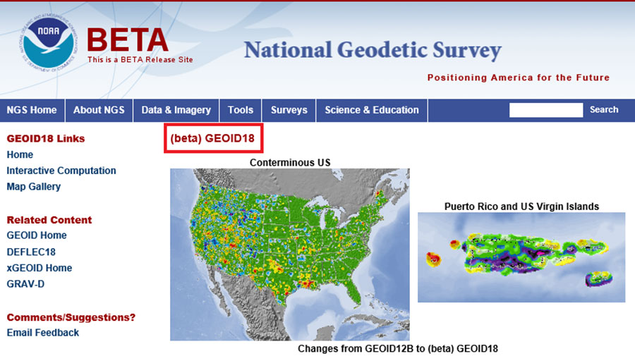
Notice announcing beta version of Geoid18 on NGS homepage. (Screenshot: NGS)
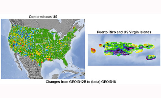
It should also be noted that in late February, NGS released a beta version of the latest hybrid geoid model, Geoid18. This model can be accessed here; the site provides an opportunity for users to compute a beta Geoid18 value for a particular station.
Excerpt from beta Geoid18 website. (Screenshot: NGS)
I would encourage all users to obtain an understanding of the new hybrid model. Once again, it should be noted that this model is a beta model for users to test their workflows and should never be used for official or production work.
My next column will discuss the beta hybrid Geoid18 model, and the differences between the beta model and the official hybrid geoid model, Geoid12B.
Inertial 2019, the sixth annual Institute of Electrical and Electronics Engineers (IEEE) International Symposium on Inertial Sensors and Systems, took place in Florida earlier this month. Events of particular note included two keynote talks from experts at the U.S. Defense Advanced Research Projects Agency (DARPA) and the Air Force Institute of Technology (AFIT), and a technical paper on the “Design and Performance of Wheel-mounted MEMS Inertial Measurement Unit (IMU) for Vehicular Navigation.”
Miniature Sensors. Ronald Polcawich from DARPA addressed “Miniature Navigation Grade Inertial Sensors: Status and Outlook.” The agency’s Precise Robust Inertial Guidance for Munitions (PRIGM) program has focused for more than three years on developing inertial sensor technologies to enable PNT in GPS-denied environments. PRIGM has developed a navigation-grade inertial measurement unit (NGIMU) based on micro-electromechanical systems (MEMS) platforms. The device has a mechanical/electronic interface compatible with drop-in replacement for existing tactical-grade IMUs on legacy U.S. Department of Defense (DoD) platforms.
PRIGM’s second main area of interest is advanced inertial micro sensor (AIMS) technologies for future gun-hard, high-bandwidth, high-dynamic-range, GPS-free navigation. It explores alternative technologies and modalities for inertial sensing, including photonic and MEMS-photonic integration, as well as novel architectures and materials systems.
Map-Matching. Aaron Canciani from AFIT educated the many computer scientists, software developers, information technology professionals, physicists and electrical and electronics engineering attendees on “The Importance of INS Accuracy for Map-Matching Navigation.”
The GPS-alternative technique matches measurements from a sensor to a map to provide navigation information. With repeatable measurements, almost any map may be used to navigate. Common maps used for navigation include terrain height, gravity, magnetic fields, Wi-Fi RSS and more. The inertial navigation system often plays a critical role in the accuracy of these methods, and increased INS accuracy plays a synergistic role in an overall map-matching navigation system.
WHEEL-MOUNTED IMUS
In today’s automobiles, MEMS gyroscopes and accelerometers provide essential measurements for enhancing stability and control. Both types of sensors have significant noise at low frequencies, limiting the measurement accuracy, particularly in low-dynamic conditions. Further, uncompensated accelerometer tilt causes large bias to acceleration estimates. For gyroscopes, physical rotation of the sensor can remove the constant part of the gyro errors and reduce low-frequency noise. In ground vehicles, such rotation occurs conveniently in wheels.
When inertial sensors are attached to the wheel, both types of sensors provide information on the rotation, gyroscopes naturally and accelerometers via specific force measurement. As a result of carouseling, accurate wheel heading, roll and pitch estimation can be estimated with high resolution, and the result is nearly bias-free. Combining the wheel orientation to distance traveled via known radius enables classic dead-reckoning mechanization (assuming zero slip) and other vehicle dynamics monitoring systems (considering wheel slip as unknown to be solved).
Authors Jussi Collin of JC Inertial Oy, Finland, and Oleg Mezentsev, Pacific Inertial Systems Inc., Canada, provided details of wheel-mounted inertial system hardware and algorithms and showed test results for several system configurations and applications. They discussed future system improvements — in particular, system miniaturization and an energy-harvesting development progress for next-generation inertial systems.
They have designed a wheel-mountable sensor system that contains MEMS sensors, battery, Bluetooth module and electronics to run computations and navigation algorithms on board. It operates in several programmable modes:
Computes navigation parameters real time and sends them via Bluetooth to an onboard computer (can be any other integrated system, data logger or a tablet).
Sends real-time raw data to an onboard computer.
Records high-rate raw sensor data (up to 2 kHz) to an embedded micro-SD card.
The onboard computer is a MEMS-array IMU with 48 gyro and accelerometer channels, with a BT receiving and sync controller, data storage and Wi-Fi interface. They can connect up to four such units to one onboard computer and have all their data in sync with the in-cabin inertial data. All of this data can be used for navigation, wheel dynamics measurements or road quality monitoring applications.
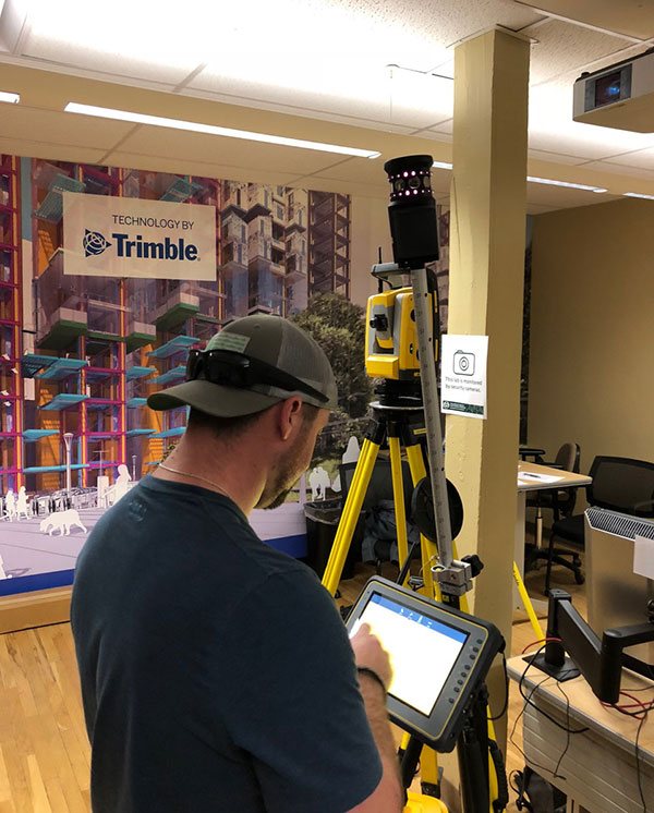
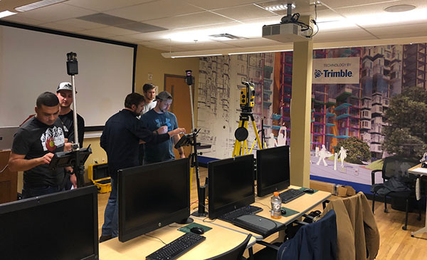
Trimble has awarded a significant in-kind gift to the Department of Construction Management at Colorado State University (CSU) that will expand the university’s leadership in training and research for 3D building design, construction management, digital fabrication, civil infrastructure, geomatics and the sustainable built environment.
The gift will enable CSU to integrate across its curricula Trimble solutions that are rapidly transforming how building and living environments are designed and constructed.
Trimble’s portfolio of building construction solutions support the Constructible Process, Trimble’s approach for enabling digital transformation of architecture, engineering and construction (AEC) workflows. This process empowers disparate teams across the construction lifecycle with actionable data to improve productivity and reduce waste.
The gift will be recognized as “Technologies by Trimble” throughout the Department of Construction Management.
Photo: Trimble
The department’s labs will include Trimble laser scanning, Trimble Field Link and Rapid Positioning Systems, UAS and surveying systems, and GNSS receivers. Trimble’s software packages will include RealWorks scanning software, Trimble Business Center, Vico Office Suite, Tekla Structures, Sefaira Architecture and its 3D modeling software SketchUp Pro, along with MEP software such as AutoBid SheetMetal and Mechanical, Sysque and AccuBid Electrical estimating packages.
Potential applications of these technologies include scanning historic and other buildings to ensure their preservation as well as planning future renovations; designing and 3D printing of architectural building models; surveying and layout; and improving construction estimating and scheduling to reduce costs.
“Working with Trimble represents the culmination of a fruitful, multi-year collaboration between CSU’s Department of Construction Management and Trimble,” said Jon Elliott, assistant department head and undergraduate program coordinator in the Department of Construction Management.
“Through numerous pieces of Trimble hardware and software applications, students gain important exposure to cutting edge technologies in surveying, virtual design and construction (VDC)-based estimating, site logistics, 3D modeling, building energy performance analysis, laser scanning, photogrammetry, and so on.
“Beyond the applications, Trimble’s dedicated employees provide outstanding educational opportunities through software demonstration and training. Through this exciting collaboration, Trimble is making significant contributions to our goal of preparing construction management students for a technologically advanced and dynamic construction industry.”
“Collaborating with CSU’s Department of Construction Management has been exciting. Trimble’s portfolio is highly relevant for students at the university,” said Roz Buick, Trimble vice president. “It will be rewarding to see the next generation of architecture, engineering, construction and building operations professionals experience the breadth and depth of our construction lifecycle solutions. We also look forward to supporting and learning from these new professionals as they experience and apply our solutions to real-world applications in their curricula.”
The gift was made to CSU’s Construction Management Program in the College of Health and Human Sciences.
Komatsu Australia and Skycatch Inc. are partnering to boost the efficiency of construction, mining and quarry sites across Oceana with the High Precision Package.
The High Precision Package is also known as Komatsu’s Everyday Drone Solution, a key component to the Smart Construction workflow.
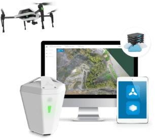
The Everyday Drone contains the Explore1 high-precision UAV, the Edge1 integrated GNSS base station and edge compute module, and the Viewer, an online data visualization and analysis tool, packaged into a commercial-grade kit.
High-precision package. (Photo: Skycatch)
The Everyday Drone allows a user to experience time to data without needing ground control points (GCP), and the ability to seamlessly integrate precision aerial data into their Smart Construction Workflow.
In common construction workflows, the time to data using traditional surveying methods could take weeks until project stakeholders can view or analyze their job site data. With the Edge1, customers are able to leverage a seamless GCP free workflow that consistently delivers sub 50-mm accurate data, in arbitrary or local coordinate systems within 30 minutes, saving countless hours and labor costs.
“We are now using the Everyday Drone at the start of projects to collect whole site information for pre-tender and bidding capability, comparing against 3D design surface to provide fleet and project managers real, accurate information viewed in the Smart Construction Application,” said Aaron Marsh, national technology solution expert manager, Smart Centre, Komatsu Australia. “This allows them to work out their cut and fill volumes with accuracy from the beginning, and enables the project tender team to select the right machines for the project optimising fleet recommendation and empowering the team to make the right, data-based decisions from the start.”
“Skycatch is proud to offer a better way of accessing precision data on-site. With traditional methods, the solutions are piecemeal, cumbersome, and time-consuming,” said Christian Sanz, Skycatch founder and CEO. “Now, customers are able to make informed decisions about changes to what was planned and what is actually happening on site in near real-time, ultimately providing greater productivity, increased profit and reducing project risk from beginning to end,”
Customers tested the receptiveness of the Everyday Drone Solution, said James Mackenzie, national remote support manager at Komatsu Australia. They first tested in civil construction, and then quickly expanded into quarry sites. Mackenzie was able to survey six quarries in five days for different customers, post-processed in the cloud, receiving the data back the next day.
“Compared to a traditional survey, this is 100% more productive and efficient,” Mackenzie said. “By using the Everyday Drone, customers are no longer putting themselves in harm’s way, surveying around heavy machinery or climbing up unstable stockpiles at risk of twisting an ankle.”
He also noted that customers appreciated the fast turn-around time, the ease of use, and the ruggedness of the products.
“Skycatch’s ability to provide near real-time data throughout the entire project is vital, and being able to deliver that to the customer, supervisor and give project teams the ability to make decisions throughout the project easily with usable, accurate data is key to the success of the project as a whole, not just in siloed environments is priceless,” Marsh said.