WaterOne found itself stuck in the past. The independent public utility knew that its workflow for collecting geospatial data was broken.
WaterOne serves a 272-square-mile area on the Kansas side of the Kansas City, Missouri, metropolitan area, which has a population of 420,000, 145,000 metered accounts and 2,685 miles of water pipes. The survey/geospatial staff consisted of three analysts, two editors, one programmer and one GPS collector. By 2016, less than 40 percent of the water features had been captured with GPS.
The staff was using legacy GNSS handhelds — operators had to return to the office every night and physically download their data.
Besides being time-consuming, the operators would become frustrated by the antiquated system. Sometimes the handhelds wouldn’t sync to the computer, or files for download would be hard to find. Also, the GNSS handhelds had a tiny screen, making it difficult for operators to see background data in the field. The handhelds’ limited computing power meant the entire water system couldn’t be loaded onto it.
WaterOne turned to a new workflow using Panasonic ToughPad tablet computers and Eos Positioning Systems’ Arrow 200 RTK GNSS receivers mounted on a range pole (see photo).
The Arrow 200 receiver connects to the Panasonic ToughPad via wireless Bluetooth link. The ToughPad has a Verizon SIM card for internet connectivity, used for two purposes:
Connecting to the Missouri Department of Transportation RTK network to receive RTK corrections for centimeter accuracy;
Connecting to the WaterOne ArcGIS server in real time from the field.
Whenever the field tech collects data, the data syncs up with ArcGIS server. This eliminates the task of having to physically download the data at the end of the day.
The new workflow also provides near real-time updates to WaterOne’s geospatial information system. This means that if five techs are in the field collecting data, they can each see the map updated in near real time.
The ToughPad tablets have a large, sunlight-readable 10-inch display. The large displays combined with the new data-collection software allows the field techs to view the entire GIS water system on the tablets. The field tech can now “see” all of the water system assets — pipes, valves, fittings, hydrants — around them. This significantly improves productivity over the legacy GNSS handhelds.
Street maps and aerial photos were loaded on the ToughPad to give the field techs a choice of background data to view.
The result? Compared to the 1,767 GPS points collected in 2016, the WaterOne team has collected 5,770 just in the first four months of 2017.
u-blox, Bosch, Geo++ and Mitsubishi Electric are establishing the joint venture Sapcorda Services to bring high-precision GNSS positioning services to mass markets, including autonomous driving.
Bosch, Geo++, Mitsubishi Electric and u-blox have created Sapcorda Services GmbH, a joint venture that will bring high-precision GNSS positioning services to mass-market applications.
The four companies recognized that existing solutions for GNSS positioning services do not meet the needs of emerging high-precision GNSS mass markets.
As a result, they decided to join forces to facilitate the establishment of a worldwide available and affordable solution for system integrators, OEMs and receiver manufacturers. Each partner brings its unique expertise to the joint venture Sapcorda Services.
Sapcorda will offer globally available GNSS positioning services via internet and satellite broadcast and will enable accurate GNSS positioning at centimeter level. The services are designed to serve high-volume automotive, industrial and consumer markets.
The real-time correction data service will be delivered in a public, open format and is not bound to receiver hardware or systems. More information will be made available later this year.
“We believe this initiative with Bosch, Geo++ and Mitsubishi Electric to create Sapcorda Services will bring a truly disruptive GNSS service offering to the market,” said Daniel Ammann, executive VP and co-founder at u-blox. “Key characteristics such as security, safety and mass-scalability, coupled with an attractive business model and an open approach — serving all interested GNSS receiver manufacturers alike — will be a game-changer across a large number of established and emerging applications.”
“We are looking forward to collaborating with our partners in this joint venture,” said Jumana Al-Sibai, member of the executive management of the Chassis Systems Control division of Robert Bosch GmbH. “Together, we want to create a GNSS positioning service that fully supports the requirements for positioning sensors in the automotive sector. Only with built-in safety and the highest levels of precision will we be able to make automated driving reality.”
“Geo++ anticipates defining the future of high precision positioning services with our partners at Bosch, Mitsubishi Electric and u-blox. The combination of the partners’ longstanding leadership in automotive and mass market solutions with Sapcorda’s commitment to push open formats will pave the way for a raft of next generation GNSS applications,” said Gerhard Wübbena founder & president of Geo++.
“Mitsubishi Electric aims to create a border-less global market for high-precision positioning systems where receivers will be able to enjoy real-time correction data services potentially interoperable with the Japanese government’s Centimeter Level Augmentation Service (CLAS) via the Quasi-Zenith Satellite System,” said Masamitsu Okamura, executive officer in charge of Electronic Systems at Mitsubishi Electric Corporation. “We believe that this venture will accelerate adoption of automated driving and safe driving support.”
Figure 1. Galileo constellation and occupation status of orbital slots (RAAN: right ascension of the ascending node, May 9, 2017). (Source: ESA)
What to Expect with the Current Constellation
This article demonstrates the benefits of Galileo integration for high-precision real-time kinematic (RTK) through representative case studies, considering baseline length, multipath impact and tree canopy.
The results confirm usability of the current Galileo constellation in high-precision RTK applications and show improved availability, accuracy, reliability and time-to-fix in difficult measuring environments.
Plus, Galileo-only RTK positions are compared with GPS-only and GLONASS-only solutions.
By Xiaoguang Luo, Jun Chen and Bernhard Richter, Leica Geosystems AG
Until now, based on simulated and observed data, the benefits of Galileo (FIGURE 1) for high-precision RTK have been investigated in single-base RTK and network RTK solutions. Building on the results of previous studies that frequently employed theoretic analysis and simulation, we present the benefits of Galileo for high-precision RTK based on real observations from the current Initial Operational Capability (IOC) satellite constellation. Using up-to-date real-time corrections including Galileo, we analyze the performance of network RTK under different measuring conditions with respect to availability, accuracy, reliability and time-to-fix.
To achieve the maximum inter-operability with other GNSS con-stellations, all the Galileo signals in the E1 and E5 band, i.e. E1, E5a, E5b and AltBOC (alternative binary offset carrier), are used for positioning in the latest proprietary firmware and receivers (see “Manufacturers” section for details).
The Galileo E1 signal is overlapped with the GPS L1 signal at a center frequency of 1575.420 MHz, whereas the Galileo E5a and GPS L5 signals are overlapped at 1176.450 MHz. As far as BeiDou is concerned, the E5b frequency of Galileo corresponds to the B2 frequency of BeiDou-2 at 1207.140 MHz.
The AltBOC signal is also supported in order to benefit from its superior performance in multipath suppression. The availability of more than two frequencies is beneficial for ionospheric modeling, which plays an important role in ambiguity resolution on the fly.
In addition, multi-frequency RTK provides more immunity to temporary interruption of GNSS signals caused by interference or by site-specific effects like multipath. When forming linear combinations, the incorporation of multi-frequency signals enhances flexibility and robustness, where the mathematical correlations introduced by including the same signal in different linear combinations of the same type need to be handled properly in RTK algorithms.
By enabling the tracking of Galileo satellites in the aforementioned firmware, the Galileo signals will be used in different RTK position types by default, including navigation position, phase-aided differential code position, extended RTK (xRTK) position and RTK fixed position. When compared to a standard RTK fix, an xRTK fix is provided at a slightly lower accuracy level, but with higher availability in difficult environments such as urban canyons and dense canopy.
In terms of RTK correction data formats, Galileo is included in the standardized RTCM v3 MSM format and in the proprietary 4G format. To use Galileo in network RTK, the real-time products provided by network correction services need to include Galileo as well. In the latest version of a proprietary GNSS network software, Galileo is used in network processing to provide RTK corrections via the individualized master-auxiliary (iMAX) method and the virtual reference station (VRS) method in the RTCM 3.2 MSM formats.
RTK PERFORMANCE CHARACTERISTICS
Multi-constellation and multi-frequency GNSS RTK is a complex real-time process, aiming to provide cm-level positioning accuracy with as few as possible data epochs for variable user kinematics and even in difficult measuring environments. Therefore, RTK performance characteristics need to be carefully selected to be able to evaluate the system as a whole and to address users’ concerns in their applications.
The following parameters are used in this article to assess the benefits of Galileo for high-precision RTK:
Satellite usage. Number of satellites used in RTK fixed solutions with an elevation cut-off angle of 10°;
Availability. Percentage of RTK fixed positions relative to all positions obtained during a time period;
Accuracy. Deviation of RTK fixed positions from ground truth with a higher degree of accuracy, where the ground truth can be determined by means of a total station or by post-processing long-term GNSS data;
Reliability. Percentage that the position error (with respect to ground truth) is less than 3 x coordinate quality (CQ) indicator;
Time to Fix. Time needed to regain an RTK fixed solution after losing ambiguity fix provided that GNSS signal tracking is not interrupted.
OPEN-SKY CASE STUDY
The open-sky case study was performed in the Heerbrugg testbed. Two receivers were connected to a single antenna via a four-way antenna splitter. One receiver received four-system iMAX corrections in the RTCM v3 MSM format over a short baseline of 2 km, whereas the other received RTK data of the same type over a long baseline of 116 km. By considering different baseline lengths, the open-sky experiment focused on the usability of the current Galileo constellation in GNSS RTK under normal conditions. Two days of 1-Hz GNSS data were investigated with respect to satellite usage and positioning accuracy.
Using different combinations of GNSS to analyze the short baseline data — GPS+GLO (GG), GPS+GLO+BDS (GGB) and GPS+GLO+GAL+BDS (GGGB) — the mean numbers of used satellites are 15, 17 and 20, respectively, where the elevation cut-off angle was set to 10°. On average, three Galileo satellites contribute to RTK fixed solutions.
For the four-system combination GGGB, Figure 2 shows the satellite usage for each individual system over the two-day period. It can be seen that for a short baseline of 2 km, a maximum number of four Galileo satellites can be used for positioning. In fact, during 80.3% of the whole test period, the number of Galileo satellites used in RTK fixed solutions is equal to or greater than the number of BeiDou satellites used.
Figure 2. Number of satellites used in RTK fixed positions with GGGB under open sky (iMAX, RTCM v3 MSM, baseline length: 2 km, GGGB: GPS+GLO+GAL+BDS, DOY: day of year).
Table 1 provides statistics on Galileo satellite usage in case of GGGB for different baseline lengths. As would be expected, the number of Galileo satellites used decreases with an increasing baseline length. In approximately 41% of the cases, three Galileo satellites are used in the short baseline test, whereas two Galileo satellites are used in the long baseline test.
Moreover, the probability that no Galileo satellites are involved in a four-system combined solution grows significantly from 1.9% to 15.0% as the baseline length increases from 2 km to 116 km. The probability that only one Galileo satellite is used under open sky is relatively small, amounting to around 0.5%. This is reasonable since no benefits for high-precision RTK are expected in this particular situation. Regarding the short baseline case, there is a 97.7% probability that at least two Galileo satellites are used for positioning, whereas this probability decreases to 84.4% in the long baseline case.
Table 1. Probability [%] that n Galileo satellites are used in RTK fixed positions with GGGB during the two-day period of the open-sky experiment (iMAX, RTCM v3 MSM, GGGB: GPS+GLO+GAL+BDS).In terms of positioning accuracy, Figure 3 compares the 3D errors from analyzing the long baseline data with different GNSS constellations. Regarding the entire two-day period illustrated in Figure 3a, the integration of BeiDou (GG vs. GGB) and Galileo (GGB vs. GGGB) results in higher position repeatability with more consistent errors. For a selected period of 12 hours, Figure 3b highlights the advantages of Galileo in reducing large 3D errors from 6–8 cm to 3–4 cm, where two or three Galileo satellites are used in case of GGGB.
Figure 3. 3D errors of RTK fixed positions under open sky (iMAX, RTCM v3 MSM, baseline length: 116 km, GG: GPS+GLO in green, GGB: GPS+GLO+BDS in blue, GGGB: GPS+GLO+GAL+BDS in red, DOY: day of year) (a) Entire two-day period, (b) Selected 12-hour period (28–40 h).
MULTIPATH CASE STUDY
In this case study, a GNSS smart antenna was set up in a location with strong multipath effects, where GNSS signals were obstructed and reflected by the surrounding buildings (Figure 4). This test setup simulates the use case that a user measures a point near a building with degraded GNSS signal reception, even at high elevation angels.
Figure 4. Test setup in a strong multipath environment in Heerbrugg (rover: GS16, antenna height: 1.8 m) (a) View from the south, (b) View from the north.
The default elevation cut-off angle of 10° was applied. The receiver received four-system VRS corrections in the RTCM v3 MSM format, where the distance to the physical reference station was approximately 200 m. Three hours of 1-Hz GNSS data were analyzed with respect to accuracy, reliability and time to fix.
Figure 5 illustrates the 3D errors from multi-GNSS RTK with and without Galileo (GGGB vs. GGB), along with the number of used satellites. Regarding the periods marked with dashed rectangles, the inclusion of two or three Galileo satellites (Figure 5b) leads to significant improvements in positioning accuracy at the few cm to dm level (Figure 5a). By comparing the empirical cumulative distribution function (CDF) of the 3D errors, the probability that 3D error is within 5 cm increases from 70% to 85% if Galileo is used, even with a maximum number of three satellites.
Figure 5. Impact of Galileo integration on RTK positioning accuracy under strong multipath (VRS, RTCM v3 MSM, GGB: GPS+GLO+BDS in blue, GGGB: GPS+GLO+GAL+BDS in red, DOY: day of year) (a) 3D errors of RTK fixed positions, (b) Number of used satellites (Galileo in green).
Tables 2 and 3 provide the root mean square (RMS) errors and reliability of RTK fixed positions from the multipath experiment, respectively. By using Galileo in high-precision RTK, the 3D RMS error is significantly reduced by 56.3% in this case study, from 0.080 m (GGB) to 0.035 m (GGGB). When compared to the horizontal components, the height RMS error shows a larger relative improvement of 58.7% due to Galileo integration. The reliability reflects the consistency between the actual position error with respect to ground truth and the CQ indicator estimated based on mathematical models in RTK algorithms. As shown in Table 3, the 3D reliability improves by 7.3%, from 88.2% (GGB) to 95.5% (GGGB), where the increases for the horizontal components and height are comparable.
Table 2. Root mean square errors [m] of RTK fixed positions under strong multipath (VRS, RTCM v3 MSM, GGB: GPS+GLO+BDS, GGGB: GPS+GLO+GAL+BDS).Table 3. Reliability [%] of RTK fixed positions under strong multipath (VRS, RTCM v3 MSM, GGB: GPS+GLO+BDS, GGGB: GPS+GLO+GAL+BDS).The time to fix (TTF) was determined by constantly re-initializing RTK once an ambiguity fix was gained. During the whole period of repeatedly resetting the RTK filter, the GNSS signals were tracked continuously without interruption. A total of 765 TTF values were obtained with GGB, whereas 1,128 TTF estimates were available with GGGB. The significantly larger number of the TTF samples from GGGB indicates higher availability of RTK fix if Galileo is used.
Figure 6 shows the statistical distribution of TTF with respect to Galileo integration. As can be seen in the empirical CDF in Figure 6a, it takes shorter time for GGGB to regain an ambiguity fix. As an example, GGGB allows ambiguity resolution within 5 s (10 s) with 46% (87%) probability, which is 29% (16%) higher than GGB. Regarding the boxplots of TTF in Figure 6b, GGGB shows a smaller median (by 25% from 8 s to 6 s) and a smaller interquartile range (IQR; by 50% from 4 s to 2 s) than GGB, where the IQR is the length of the box. This indicates that the integration of Galileo enables a faster ambiguity resolution with more consistent fixing performance.
Figure 6. Impact of Galileo integration on time to fix (TTF) statistics under strong multipath (VRS, RTCM v3 MSM) (a) Empirical cumulative distribution function (CDF) of TTF, (b) Boxplot of TTF with median and interquartile range (IQR).
CANOPY CASE STUDY
In this case study, a receiver was connected to an antenna under tree canopy (Figure 7), where GNSS signals are blocked, attenuated and reflected, leading to decreased number of observations, low data quality and degraded RTK performance.
Under these circumstances, the inclusion of Galileo satellites transmitting multi-frequency signals could be particularly beneficial for high-precision RTK. Using an elevation cut-off angle of 10°, the receiver received four-system iMAX corrections in the RTCM v3 MSM format, where the baseline length was 116 km. A long baseline was intentionally selected as an additional challenge for the RTK system. About seven hours of 1-Hz GNSS data were investigated regarding availability, accuracy and reliability.
Figure 7. Test setup under canopy in Heerbrugg (rover: GS10, antenna: AS10).
Figure 8 illustrates the impact of Galileo integration on RTK availability and accuracy under canopy, along with the number of used satellites. As can be seen in Figure 8a, the inclusion of Galileo improves the availability of RTK fixed positions by 12.2%, from 65.7% (GGB) to 77.9% (GGGB). Moreover, dm-level position errors are largely reduced, as shown in FigURE 8c. The improvements in availability and accuracy are achieved by using up to three Galileo satellites (Figure 8b). This demonstrates that the current Galileo constellation in the IOC phase brings considerable benefits to high-precision RTK under canopy conditions.
Figure 8. Impact of Galileo integration on RTK availability and accuracy under canopy (iMAX, RTCM v3 MSM, baseline length: 116 km, GGB: GPS+GLO+BDS in blue, GGGB: GPS+GLO+GAL+BDS in red, DOY: day of year) (a) Availability of RTK fixed positions over time, (b) Number of used satellites (Galileo in green), (c) 3D errors of RTK fixed positions.
Tables 4 and 5 provide the RMS errors and reliability of RTK fixed positions from the canopy experiment, respectively. The main factors degrading the RTK accuracy in this case study are not only the canopy environment, but also the long baseline length of 116 km. It can be seen in Table 4 that the integration of Galileo leads to a significant reduction of 3D RMS error by 23.7%, from 0.114 m (GGB) to 0.087 m (GGGB).
By comparing the 2D and 1D RMS errors, the benefits of Galileo for the height are more dominant than for the horizontal components, which was also observed in the multipath experiment (Table 2). In terms of reliability, only slight (below 2%) increases are visible in Table 5. 116km baseline length and heavy canopy are considered extreme conditions and beyond the standard conditions relevant for specifications. Considering reliability together with availability (Figure 8a), it is encouraging to see that both the RTK performance characteristics are improved in this case study.
Table 4. Root mean square errors [m] of RTK fixed positions under canopy (iMAX, RTCM v3 MSM, baseline length: 116 km, GGB: GPS+GLO+BDS, GGGB: GPS+GLO+GAL+BDS).Table 5. Reliability [%] of RTK fixed positions under canopy (iMAX, RTCM v3 MSM, baseline length: 116 km, GGB: GPS+GLO+BDS, GGGB: GPS+GLO+GAL+BDS).
GALILEO-ONLY RTK
To optimize the performance of multi-GNSS RTK positioning, the individual systems need to be fully understood and mastered. With a previous firmware release in August 2014, mass-market devices were able to perform GLONASS-only and BeiDou-only high-precision RTK. In 2014 tests, we compared the performance of GPS-only, GLONASS-only and BeiDou-only RTK at different accuracy levels. Considering that Galileo has reached the IOC phase, it is reasonable to assess the Galileo-only RTK performance with the latest firmware.
Due to the limited number of usable Galileo satellites, Galileo-only RTK positioning was carried out in the Heerbrugg open-sky testbed over a very short baseline of 1 m. In addition, the elevation cut-off angle was set to 0° in order to track as many Galileo satellites as possible simultaneously. Two receivers were connected to two choke-ring antennas with good low-elevation tracking ability. Single-base RTK positioning was performed with four-system corrections in the RTCM v3 MSM format. About one hour of 1-Hz GNSS data was analyzed with a special focus on positioning accuracy.
Figure 9 shows the 3D errors from GPS-only, GLONASS-only and Galileo-only RTK positioning, where the numbers of used satellites are 8–11, 7–9 and 5–6, respectively. During the test period, only three or four BeiDou satellites were tracked with poor geometry, making BeiDou-only RTK impossible. As the figure shows, the 3D errors from GPS-only and Galileo-only RTK are at a comparable level with similar RMS values, whereas the 3D RMS error from GLONASS-only RTK is almost twice as large as the GPS/Galileo-only case. Note that when compared to GPS-only RTK, almost half as many satellites are used in Galileo-only RTK.
Figure 9. 3D errors of RTK fixed positions from GPS-only, GLONASS-only and Galileo-only RTK under open sky (single-base RTK, baseline length: 1 m, RTCM v3 MSM, DOY: day of year, RMS: root mean square).
Figure 10 displays the statistical distribution of the 3D errors from GPS-only, GLONASS-only and Galileo-only RTK positioning. Regarding the empirical CDF in Figure 10a, GPS/Galileo-only RTK shows a clearly more favorable error distribution than the GLONASS-only case. Using only GPS or Galileo, the probability that 3D error is within 1 cm is above 80%, which is approximately 30% higher than using only GLONASS. For 3D errors ranging between 5 mm and 1.7 cm, Galileo-only RTK even provides a slightly higher cumulative probability than the GPS-only case. The 3D error boxplots in Figure 10b illustrate a similar pattern between GPS-only and Galileo-only RTK, which is superior to GLONASS-only RTK due to the significantly smaller median and IQR.
Figure 10. 3D error statistics from GPS-only, GLONASS-only and Galileo-only RTK under open sky (single-base RTK, baseline length: 1 m, RTCM v3 MSM). (a) Empirical cumulative distribution function (CDF) of 3D errors, (b) Boxplot of 3D errors (IQR: interquartile range).
CONCLUSIONS
With the declaration of Galileo Initial Services in December 2016, for the first time ever all GNSS users worldwide are able to use the positioning, navigation and timing information provided by Galileo’s global satellite constellation. Upon full system completion by 2020, Galileo will play an important role in high-precision GNSS applications for users around the world. This article showed representative case studies to understand the benefits of the current Galileo constellation for high-precision RTK. In addition to a multi-GNSS solution, the performance of Galileo-only RTK was presented. The main findings from the case studies can be summarized as follows:
In the open-sky test, with an elevation cut-off angle of 10°, on average three Galileo satellites can be used for high-precision multi-GNSS RTK. This leads to cm-level improvements in coordinate repeatability over a long baseline of 116 km.
In the multipath case study, the additional use of two or three Galileo satellites produces significant enhancements in positioning accuracy at the few cm to dm level, where the benefits for the height component are more significant. Moreover, the integration of Galileo increases the 3D reliability of RTK fixed positions by 7.3% and reduces the median time to fix by 2 s (25%).
In the canopy experiment, the inclusion of Galileo improves the availability of RTK fixed solutions by 12.2%. Furthermore, dm-level position errors are largely reduced.
When compared to GPS-only RTK, Galileo-only RTK provides a similar positioning accuracy over a 1-m baseline under open sky, where almost half as many satellites are used. The 3D RMS error from GLONASS-only RTK is approximately twice as large as the GPS/Galileo-only case.
The promising results achieved through Galileo integration already indicate the very important role of the European GNSS in high-precision, multi-frequency and multi-constellation RTK positioning. During the deployment of the Galileo system, more benefits can be expected in the near future.
ACKNOWLEDGMENTS
The staffs of Leica Geosystems AG (Heerbrugg/Switzerland), Christian Waese and Youssef Tawk, are gratefully acknowledged for support in setting up the variety of RTK network streams.
MANUFACTURERS
SmartWorx 6.16 of Leica Viva GNSS is the latest firmware cited and used in these high-precision RTK tests. Leica GNSS Spider 7.0.0 furnished the GNSS real-time corrections. The open-sky case study used two Leica Viva GS10 units connected to a Leica Viva AS10 antenna via a four-way antenna splitter. The multipath case study used a Leica Viva GS16 GNSS smart antenna. The canopy case study used a Leica Viva GS10 receiver and a Leica Viva AS10 antenna. The Galileo-only RTK test used two Leica Viva GS10 receivers and two Leica AR25 choke ring antennas.
In the battle for reliable positioning and timing, the U.S. Army is engaged in a multitude of activities, including mounted and dismounted A-PNT (assured position, navigation and timing) systems, anti-jam technology and pseudolites.
The idea is simple: Take some GPS satellites, and put them on or near the ground. Now you have a navigation system where you have full control over the locations and power of the transmissions. You can ensure that the transmissions reach places that GPS normally struggles with, such as deep urban canyons, forests and valleys.
You can turn up the transmit power, so they are much harder to jam than spaceborne GPS signals. These pseudo-satellites, commonly referred to as pseudolites, have seen steady interest over the years for a variety of applications.
Now the U.S. Army is pursuing the use of pseudolites as part of its initiative to maintain operation in GPS-denied environments.
Pseudolite Basics
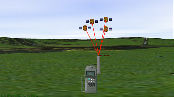
There are various types, and use-cases, of pseudolites. In this column we’ll consider the direct-ranging pseudolite, which can be simply considered as a ground-based GPS satellite. If we deploy several pseudolites on the ground, we can imagine that a normal GPS receiver would be able to receive the GPS-standard transmissions and derive a position, just as we would from the space-based satellite transmissions.
The fact that the pseudolites are ground-based introduces us to the first consideration: The locations of the transmitters are no longer described by orbital parameters. Instead of calculating the position of satellites, we need to describe the location of the pseudolites in geographical terms, perhaps with a fixed position described in Earth-centered, Earth-fixed (ECEF) coordinates.
The transmitted navigation data message, which would normally contain almanac and ephemeris information, may now need to contain the geographical position of the pseudolite. Not a problem, but our GPS receivers will need a software upgrade to be able to handle this situation.
The deployment of the pseudolites themselves poses an interesting problem. Imagine a military scenario, where the army is deployed to a region of interest. Navigation warfare is taking place, and GPS is frequently jammed in the region.
High-power pseudolites are deployed to allow the army to navigate despite the jamming, using the same standard-issue GPS receivers that soldiers are familiar with.
The first problem is, having placed your pseudolites in position, how do you know where they are?
You might choose to place your pseudolites at locations that have previously been surveyed, so you know where they are in advance. But this isn’t likely, particularly if you’ve just moved your troops into an unfamiliar area. You might also want to move the pseudolites regularly, as the army moves to new ground. So the pseudolites need to determine their own position, and the easiest way for at pseudolite to determine its own position is with GPS, of course.
Isn’t this a bit incestuous? If we’re using pseudolites because GPS is jammed, how does the pseudolite get its position? This is why military pseudolites will typically be fitted with some form of anti-jam technology, such as a controlled radiation pattern antenna. This allows the pseudolite to receive GPS satellite signals in the presence of jamming, determine its own position, and transmit that as part of its own navigation message.
So, now that we can get pseudolite locations, the next consideration is: Where should pseudolites be placed?
A-DOP-ting a Good Layout
If you know about GNSS, you’ll be familiar with the concept of dilution of precision (DOP). This is essentially a measure of how accurate your position estimate is likely to be, due to the geometry of the satellites: a good wide spread of satellite positions gives us better accuracy.
Figure 1. Poor satellite geometry, resulting in high DOP. (Image: Michael Jones)Figure 2. Good satellite geometry, resulting in low DOP. (Image: Michael Jones)
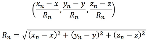
The DOP can be easily calculated by forming a covariance matrix of the geometry, expressed in an appropriate coordinate frame. If (xn, yn, zn) denotes the position of the nth pseudolite, and (x, y, z) the position of the receiver, we can express the unit vectors from the receiver location to the pseudolite location:
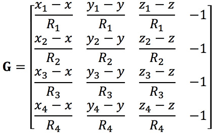
We then form a matrix of these unit vectors:
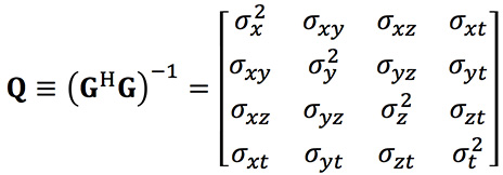
Finally, we form the covariance matrix from which we can extract the DOP values:
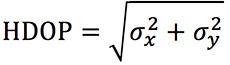
From the elements of this matrix we can determine the various DOP metrics. Let’s concentrate on horizontal DOP (HDOP), given by:
When positioning using GPS satellites, we are blessed with a Walker constellation that generally gives us a nice spread of satellite locations (unless we’re in an urban canyon). On the battlefield, using pseudolites, we do not have the same luxury.
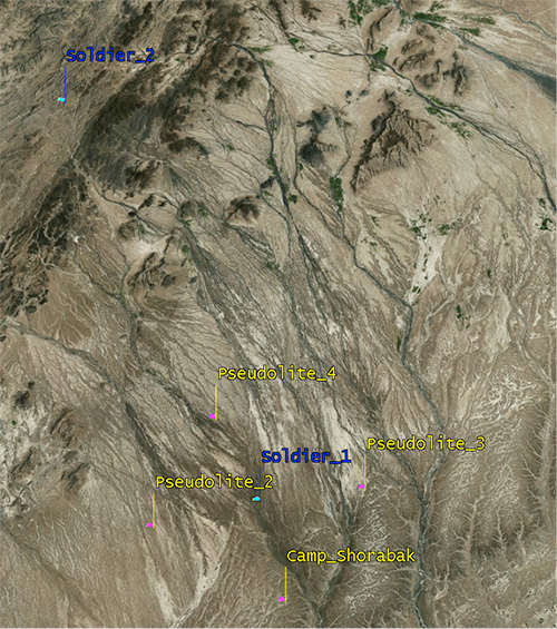
Let’s consider a scenario: a conflict in Helmand province, Afghanistan. An operating base is established at Camp Shorabak, where a pseudolite is operating, and three further pseudolites are deployed in the field. This is shown in figure Figure 3.
Figure 3. Scenario with four pseudolites. (Image: Michael Jones)
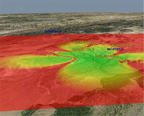
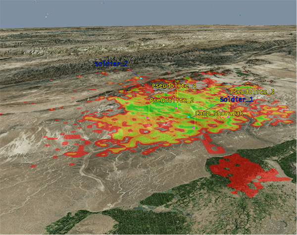
Taking a look at Figure 4, we can see what this means for HDOP. The regions shaded green represent locations where our HDOP is less than 2.5, and the red areas represent an HDOP greater than 50.
Soldier #1 is surrounded by the four pseudolites, which is a pretty nice arrangement: We get an HDOP of around 2.4. But if we now consider soldier #2, located a bit further out, we get a very different picture.
Here we have an HDOP of 64, which is fairly terrible. It’s not really that surprising looking at the geometry — to soldier #2 the pseudolites all appear in a similar direction. Soldier #2 cannot expect to achieve good positional accuracy in this arrangement.
Figure 4. HDOP for the Afghanistan scenario. (Image: Michael Jones)
So getting a good geometric spread of ground-based pseudolite locations could be a bit of a challenge, especially if the operating area is constantly moving and changing. The next thing to think about is getting enough height.
Getting the Height Right
When we perform positioning using GPS, we typically track several satellites, which have a range of elevations. Many GPS receivers will choose to ignore the satellites at low elevations, such as those within 5 degrees of horizontal, because those satellites are generally the least reliable. They may be partially obscured, and subject to more noise and fading.
Ground-based pseudolites all have very low elevations by definition. Unless the terrain is perfectly flat and smooth, pseudolites quickly become obscured. Even with flat ground, pseudolite signals will disappear behind the horizon after a few kilometers.
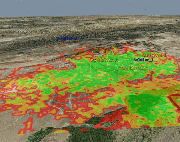
Let’s go back to our Afghanistan scenario again. This time, instead of looking at DOP, let’s look at the geographical coverage of our four pseudolites. Here we’ll assume that our user, the soldier, is 2 meters (m) high, and the pseudolite antennas are mounted at a height of 20m above the ground. That’s pretty high — the army will need to erect some masts.
Figure 5 shows what we get. The green areas are locations where our soldier can see all four pseudolites; yellow three, orange two, and red one. At all other locations, no pseudolite signals can be seen at all. You can quickly see that the range isn’t great — terrain, even small undulations in the ground, is a line-of-sight killer. Add some buildings and trees and the situation gets worse. Reduce the height of our pseudolites below 20m, and the situation gets worse. Soldier #1 can receive three pseudolite signals, but soldier #2 has no hope in this case.
Figure 5. Pseudolite visibility at 20m antenna height. (Image: Michael Jones)
Let’s raise the height of the antennas to a fairly crazy 100m above ground (Figure 6). As expected, we get much better coverage, but soldier #2 still has a problem. To get good signal coverage over any sizable area, you really do need to get those antennas as high as possible.
Figure 6. Pseudolite visibility at 100-m antenna height. (Image: Michael Jones)
Augmenting GPS
Often, we don’t want to rely on pseudolite signals alone. If GPS is available, we clearly want to make use of it, and so we want to use a mixture of both GPS satellites and pseudolites. Consider working in a region of sporadic GPS reception, such as an urban environment or forest. We can usually receive a couple of good GPS satellites, but we also need a couple of pseudolites to help us get a complete navigation solution.
Coming back to one of our original objectives, which is to avoid redesigning the GPS receiver hardware, we need to make sure that our receivers can receive and process both GPS satellite signals and pseudolite signals simultaneously. To achieve this, we can decide to make our pseudolites transmit GPS-standard signals, and make use of unassigned spreading codes to essentially create new satellites in the constellation.
But we quickly run into a problem. GPS satellites are always a distance of around 20,000 kilometers away, and the received signal strength is also fairly constant: around –158.5 dBW. This is a very small signal, as we all know, sitting well below the noise floor. When we suddenly bring high-power pseudolites into the mix, we have quite a nasty problem to deal with.
Near, Far, Wherever You Are
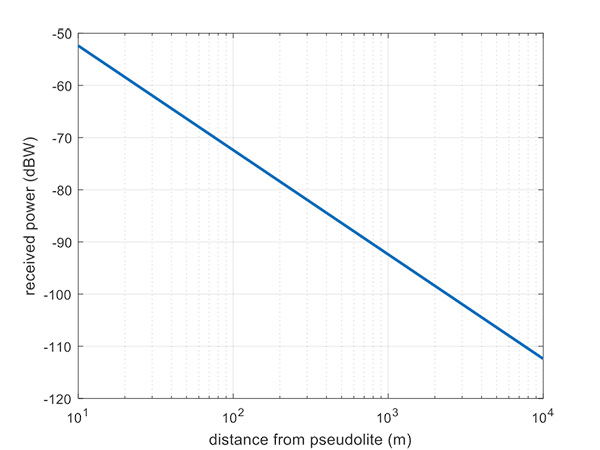
Let’s say, for argument’s sake, we have a pseudolite transmitting with a power of 1 watt. Conducting a basic link budget analysis gives us the plot below and suggests that, at a distance of 10 km from the pseudolite, we can expect to receive the signal at around –112 dBW. This is way above our GPS satellite signal level, but might be manageable by a receiver. Now consider a receiver at a distance of 100 m from the transmitter: we receive a power of –72 dBW, which is huge.
In our quest to augment GPS and make it more robust, we have in fact created a GPS jammer, and achieved exactly the opposite. As with any radio communications link, the received power is extremely sensitive to the distance (varying with the square of distance). In pseudolite terminology, this is known as the near/far problem.
Figure 7. Theoretical received power for a 1-W pseudolite, under ideal conditions. (Figure: Michael Jones)
The near/far problem has given engineers headaches for quite some time. Essentially, the problem comes down to: How can our GPS receivers handle such a massive dynamic range of expected signals? Especially if our objective is to avoid modifying the GPS receiver hardware, if at all possible.
How can a receiver handle the high power of a close-up pseudolite, which is to all intents a jammer, whilst simultaneously receiving the tiny GPS satellite signals from space? Various solutions have been proposed over the years, but one of the current favorite techniques involves pulsing the pseudolite signal.
The idea, then, is to only turn on the pseudolite periodically, essentially applying a duty cycle to the transmission. If a pseudolite isn’t transmitting, it can’t interfere with the normal GPS signals. There are a couple of things to take into consideration here:
What should the pulse duty cycle be, to enable both satellites and pseudolites to be tracked?
How does the GPS receiver behave when presented with alternating large and small signals?
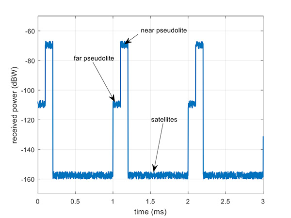
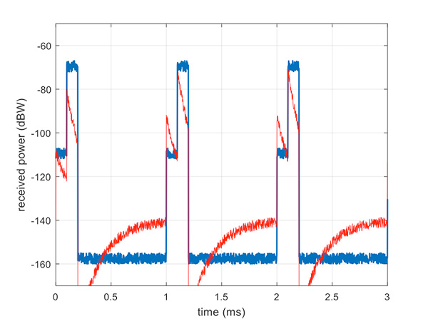
A mathematical analysis of duty cycle effects is beyond the scope of this column, but consider Figure 8 for a qualitative view. Here we have two pseudolites operating alongside GPS satellites. The duty cycle chosen here is for the pseudolite to be operational for 10% of a 1 millisecond integration period. This gives enough time, when the pseudolite is not transmitting, for the low-level GPS satellites to be tracked.
The second pseudolite, which is closer and therefore higher power, transmits for a further 10% slot after the first pseudolite. You can see that each additional pseudolite eats into the time available for tracking GPS satellites, and degrades the signal-to-noise ratio. There are some tricks you can play, such as transmitting multiple pseudolites at the same time if you know they will be similar power levels, but it can get complicated.
Figure 8. Received power versus time, for a pulsed pseudolite scenario. (Figure: Michael Jones)
The Importance of Gain Control
How the receiver copes with the large differences in received power level depends largely on the design of the RF front-end in the receiver. Most GPS receivers will have a certain amount of automatic gain control (AGC), which is a feedback loop designed to keep power levels constant. Many GPS receivers, though, simply aren’t designed with enough AGC to handle pseudolite-level signals (think GPS jammers again).
Military receivers, though, tend to have greater RF handling capabilities, and more bits in the ADC, so are better-suited to the situation. It is then a question of making sure the AGC loop responds in an appropriate time, compared to the duty cycle of pulses.
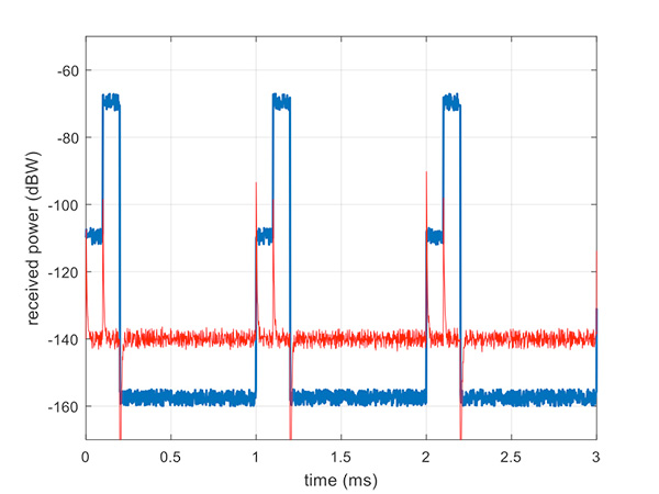
Figure 9 illustrates a slow AGC response, which is not particularly suitable. Compare this with Figure 10, where we have a fast AGC response, quickly adapting to the switches in power level. A receiver with this characteristic will be better able to track both pseudolite and satellite signals.
Figure 9. Pulsed pseudolites with slow AGC response (in red). (Figure: Michael Jones)Figure 10. Pulsed pseudolites with fast AGC response (in red). (Figure: Michael Jones)
Airborne Pseudolites
If you’ve read this far, you’ll now know that the main problems with ground-based pseudolites are lack of good geometry, signal blocking by terrain, and the horrendous near/far issues. Wouldn’t it be nice if we could raise the pseudolites to a really high altitude, and all these problems would go away? Wait, that’s the GPS satellite constellation!
Ok, let’s not put them that far up. But how about carrying pseudolites on high-altitude airborne platforms instead? Great idea, and that’s why this is a current thread of defense activity in various countries. High-altitude long-endurance (HALE) or HAPS (high-altitude pseudo-satellite; the clue is in the name) unmanned platforms can be used to carry pseudolites at high altitude.
This solution can provide excellent coverage, the pseudolites can be repositioned as necessary, and the near/far problem is also far less pronounced.
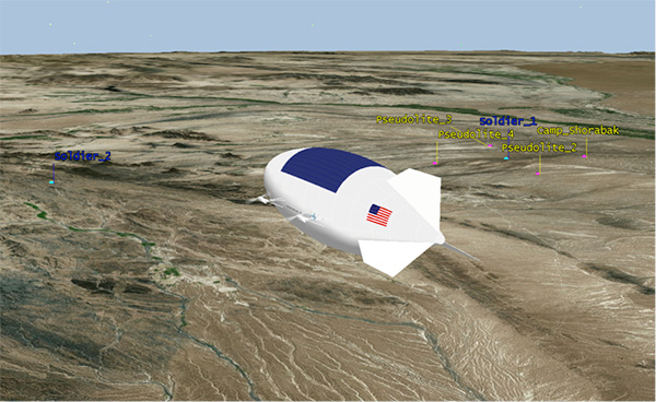
I leave you once again with our Afghanistan scenario, from the point of view of a high-altitude airship at 18,000 meters.
Figure 11. High-altitude platform, potentially carrying a pseudolite at 18,000 m. (Image: Michael Jones)
New features are now available for TerraGo Magic, including laser-rangefinder integration, offset data capture, Apple and Google turn-by-turn navigation, and proximity alerts. Also new is extended waypoint guidance for finding off-road assets and infrastructure.
TerraGo Magic is a zero-code platform-as-a-service that enables customers to build their own custom mobile apps without writing any code by choosing from a menu of available, field-tested features.
TerraGo Magic is also the underlying platform used to build TerraGo Edge, which includes these latest features in version 4.1, available for download from the iTunes App Store and Google Play.
“With the addition of laser positioning and offsets for remote data collection, TerraGo helps us rapidly capture high-accuracy data for more assets and infrastructure, even those in difficult to reach locations,” said Fernando Mutia, IS supervisor for San Jose Water Company.
Partnership with Laser Technology
TerraGo is now partnering with Laser Technology Inc. (LTI) to enable all custom apps built by TerraGo Magic to seamlessly utilize LTI’s professional-grade laser rangefinders.
TerraGo Magic partners and customers can now add TruPulse rangefinder support to their custom iOS and Android apps with the click of a button using the TerraGo Magic zero-code app platform.
Also, Seiler Instrument – Geospatial, a partner of both LTI and TerraGo, will now add TruPulse support to its new Field2GIS app, which was built using TerraGo Magic and is now available from iTunes and Google Play.
“We’re very happy to launch this partnership that we feel responds directly to our customers’ goals and the industry’s demand for improving the quality and productivity of their field data collection work,” said Derrick Reish, senior product manager at LTI. “By leveraging laser precision and cloud-based mobility, we can help our joint customers collect the accurate data they need at a level of efficiency that wasn’t possible just a few years ago.”
“With TerraGo Magic, we totally change the traditional way of thinking about how custom mobile app versions get built, released and upgraded,” said Dave Basil, vice president of product development at TerraGo. “When we publish a new feature in Magic, it’s immediately available to all customer apps but doesn’t force it on all customers or require an upgrade beyond their control.”
“With TerraGo Magic’s platform-as-a-service, customers can evaluate and include features based on their priorities, timeline, business requirements and users’ needs, giving them the flexibility and control of a custom solution without the cost of custom app development,” Basil said.
Webinars
TerraGo is hosting a webinar on Aug. 15 at 12 p.m. ET with a live demonstration of the latest features in TerraGo Magic Apps and TerraGo Edge.
To learn more about the technical details and operational benefits, join TerraGo and LTI in the webinarAdvanced Mobile Data Collection Finds the Range with Laser-Precision, on Aug. 22 at 12 p.m. ET.
General Dynamics Mission Systems has introduced its HOOK3 combat survival radio.
The HOOK3 radio is 30 percent smaller and 40 percent lighter than the HOOK2 radio, and has a smaller, longer lasting battery, the company said.
In addition, the embedded GPS module has 32 channels enabling a faster position acquisition time, more accurate position reporting and better performance under forested or densely vegetated areas or near structures.
The radio transmits encrypted GPS, user identification, situation reports and other critical information to rescue teams and aircraft in short bursts to reduce the risk of detection. The radio can also use multiple GNSS.
The new radio provides direct line-of-sight voice and encrypted two-way data communications to help combat search and rescue teams quickly and accurately locate and rescue downed pilots and isolated military personnel, the company added.
The HOOK3 was designed using feedback from military personnel who rely on a survival radio in emergency situations. The new radio automatically activates and securely transmits location data when specific G-Force or the presence of salt water is detected by the radio.
“General Dynamics has delivered more than 36,000 combat search and rescue radios to 36 countries over the past 30 years,” said Paul Parent, a vice president of General Dynamics Mission Systems. “These radios have helped save the lives of military personnel isolated or in harm’s way during a mission.”
“The HOOK3 provides military personnel in emergency situations a highly reliable, easy-to-use, secure radio critical to their successful recovery.”
The General Dynamics HOOK3 radio is interoperable with all HOOK2 family radios, Quickdraw2 and SATCOM base stations currently used by U.S. and international military personnel.
The HOOK3 is designed for coalition operations, and the user-friendly transceiver is software-defined, enabling new features, waveforms and software upgrades to be added as they become available.
A major new global-scale venture by China’s Internet giant Baidu aims to put artificial intelligence behind the wheel of fully autonomous vehicles on the road by 2020.
Regulatory considerations aside, the technical challenges are considerable, but like its U.S. counterpart Google, Baidu is pushing a big pile of chips onto its artificial intelligence (AI) bet.
Similar to Android, it has made much of the Apollo program’s code, which is completely open-source and available on Github.
The ecosystem, launched at the Baidu developers conference in Beijing in April, has enlisted at least 50 partners worldwide, with more anticipated.
A key participant is AutonomouStuff, which started out as an autonomous components supplier, but lately self-transformed into a full-fledged system integrator, with core GNSS and inertial capabilities drawn from manufacturers in the positioning, navigation and timing (PNT) industry.
Other Apollo partners include major Chinese auto manufacturers; tier 1 suppliers such as Bosch, Continental Automotive and ZF Friedrichshafen AG; components providers such as NVIDIA and Microsoft Cloud; mapper TomTom; and drive-sharing companies.
AutonomouStuff kitted out two standard Lincoln MKZ sedans for demonstration drives at the Beijing conference, with one technician completing each vehicle in about three hours — a task that would normally take a team of workers up to six weeks. The two Lincolns then drove simultaneously, driverless, around a test track.
The technology has been developed to be transferrable to other vehicles. Models already demonstrated include the Ford Fusion, a street-legal golf-cart-type electric vehicle called the Polaris GEM, and an off-road Ranger buggy platform.
AutonomousStuff presents the Apollo kit at the Baidu developer’s conference in April. (Photo: AutonomousStuff)
How It Works
Each car is modified by adding lasers, camera, radar sensors, GPS and inertial measurement unit (IMU), a drive-by-wire computer interface and computer engine.
Laser Sensors. A 64-beam lidar sensor on the roof gives a 360-degree field of vision for mapping, and lidar localization algorithms drawing on more than 2.2 million points of data per second generate a point cloud giving distance, angle and intensity values. This data is integrated with data from the GPS and IMU to generate a base map. Two smaller lidar sensors on the front corners of the vehicle provide obstacle detection and tracking.
Rotating four-beam laser sensors with 110-degree view and 200-meter range cover blind spots and facilitate fusing all raw data into one scan. Together, they detect other cars, trucks, bikes, pedestrians and background objects, and generate detailed data on their position, motion and shape. Distance and angular resolution data are used to offset camera and radar data.
Cameras. The platform uses two visible-light cameras mounted on the windshield, relying on laser sensors for nighttime operation. An image-processing chip provides real-time detection of lanes, vehicles and pedestrians, and measures dynamic distances from the vehicle.
Radar. Five radar sensors provide object detection, with various placements around the vehicle, and varying ranges and fields of view. Jointly, they provide a 360-degree bubble around the car.
Navigation. The kits provide GPS navigation combined with a tightly coupled IMU to provide data when GPS is not available.
Together, this provides accuracy to 2 cm, according to the company, when used with a real-time kinematic (RTK) base station; this obviously limits vehicle range. Another option is to use correction data from satellite-based correction services such as TerraStar, yielding achievable accuracies on the order of 4 cm.
Documentation
The aim of the Apollo project is to enable partners and customers to develop their own self-driving systems. The information supplied by Baidu encompasses a complete set of end-to-end instructions to convert a regular car to an autonomous-driving vehicle:
Software Instructions. A set of files that contain:
architecture of the classes and the files within each class.
code instructions for:
coordinate system
third-party libraries
calibration table.
Hardware Documents. Instructions to install the hardware and software for the vehicle include:
Vehicle:
industrial PC (IPC)
GPS
inertial measurement unit (IMU)
controller area network (CAN) card
hard drive
GPS antenna
GPS receiver
Software:
Ubuntu Linux
Apollo Linux kernel
Hardware reference guides:
vehicle
IPC
GPS
CAN card
https://youtu.be/eiSfP-Rn6n4
Manufacturers
The AutonomouStuff Apollo kit incorporates a choice, depending on user needs, of a selection of NovAtel GNSS receivers, including the ProPak6 GNSS receiver and the SPAN-IGM-A1 GNSS+IMU combined system, IMUs such as the IMU-ISA-100C incorporating Northrop-Grumman Litef GMBH’s inertial measurement technology, and antennas such as the GNSS-703-GGG-HV high vibration triple-frequency GPS, GLONASS, BeiDou, and Galileo antenna.
A 64-beam Velodyne lidar sensor and 16-beam HDL-16E provide laser data.
The onboard computer system is the AStuff Nebula embedded controller, an IPC powered by an Intel Skylake core i7-6700 CPU. The CAN card used for the IPC is the ESD CAN-PCIe/402.
Drones have become a serious threat, able to penetrate airspace for surveillance or with an explosive payload.
The Islamic State has used weaponized drones against both Syrian and Iraqi forces; groups like Hezbollah and Hamas have sent drones into Israel and are said to be working on upgrading their UAVs for use in both intelligence gathering and offensive operations.
On April 27, Israel used a Patriot missile to take down a drone entering Israeli Airspace from Syria. At $3 million per missile, the Patriot system is an expensive way to down a device that may only be worth $200. Israel has also intercepted drones with fighter jets.
Systems developed by two Israeli companies provide less expensive — and quickly reactive — solutions.
The Drone Dome system uses Laser, RF and Radar. (Photo: Rafael)
Drone Dome.Rafael Advanced Defense Systems Ltd. has developed a radar and laser-beam system for detecting and destroying drones, with the company adapting its existing laser systems to handle the threat.
Once the system’s radar identifies targets, its laser system destroys them.
Drone Dome also features a jamming system for disrupting communications between the drone and its operator. Drone Dome’s range reaches several miles, but causes minimal interruptions to other systems in nearby urban areas.
The standard Drone Dome system comprises a RADA RPS-42 S-band multi-mission hemispheric radar, a Controp MEOS electro-optical (EO)/infrared surveillance suite, a communications package, and the C-Guard RD jamming and NetSense Wideband detection sensor systems developed by Netline. The UAV threat is neutralized by activation of directional GPS/GNSS and radio-frequency inhibitor/jammer devices.
The RPS-42 is a four-panel tactical air surveillance system delivering 360-degree coverage in azimuth and 90 degrees in elevation, with a detection range of 30 kilometers — including the detection of a minimum target size of 0.002 meters square at a range of 3.2 kilometers — at altitudes from 30 to 30,000 feet. The RPS-42 is designed to detect, track and classify all classes of UAV.
DROM Defense.ORAD’s DROM Drone Defense System can detect an approaching drone at more than 3.5 kilometers away and take command, neutralizing it and landing it far from the operator.
With a weight of 38 kilograms, ORAD’s DROM system comes pre-engineered and pre-assembled. It is mobile and easily deployed on land or at sea in any weather conditions and has an effective coverage range of 3.5 kilometers. It has a 2-kilometer neutralization capability.
Once intercepted, the system can land a hostile a UAV in a pre-defined location, keeping any intelligence it gathered out of enemy hands. It can also identify the location of the operator.
The system’s RF detection unit analyzes signal channels and radio transmissions to spot drones. Once detected, an alarm alerts the system operator.
ORAD has sold the system to clients in several countries including Portugal, Spain and Thailand. The company is in talks with Israeli agencies interested in purchasing the system.
The Apex tracker has Taoglas inside. (Photo: STATSports)
When the world’s best athletes take the field, many are equipped with a GPS-based performance monitor that tracks a wealth of data. By monitoring in real time the players’ actions, professional sports teams can collect and analyze data that gives them an edge over the competition.
STATSports is a provider of GPS player tracking and analysis solutions for some of the biggest sports franchises in the world. Teams in the English Premier League, La Liga, National Football League, National Basketball Association and other leagues rely on STATSports to help them improve performance and strategy, and reduce injuries.
Tracking Key Metrics. STATSports’ Apex System includes the Apex Pod and Apex Software. The Apex Pod is an ergonomically designed unit that curves to fit players’ backs. The pod is inserted into a specially designed vest or base layer.
It tracks a variety of metrics, including a player’s total distance, speed, accelerations, decelerations, heart rate, fatigue level and other variables that teams can use in real time or alongside post-game reviews. The data is processed through Apex Software, which creates reports and visual tracking mechanisms to compare players, track players over time and provide metrics personalized for each team.
A tablet app gives coaches portable functionality. (Photo: STATSports)
Apex Live Streaming uses multiple channels and synchronized mesh networking to deliver data streams from players to Apex Software for analysis. Apex delivers GPS speed and positional data; heart-rate variability; and digital compass, gyroscopic and accelerometer data. It transmits half a million numbers every minute during training and games for a squad of more than 30 players.
Accurate Antenna
In devices so small and sensitive, antennas can be the most common point of failure in the communications chain, said Dermot O’Shea, co-CEO of Taoglas. STATSports evaluated several antenna options before selecting Taoglas.
Taoglas’ 25×25-mm AGGBP.25B is a two-stage 28-dB active GPS patch antenna module that provides positional accuracy in a small form factor.
With a few dozen players and coaches on the field in training and at games, highly accurate positioning is critical. Players move quickly and are often clustered around a ball, making it difficult to accurately track player movement. STATSports required location accuracy within 1 meter, precision that
Taoglas delivered.
The LA Galaxy team uses STATSports. (Photo: LA Galaxy)
Because the STATSports technology captures data in real time, teams can make real-time tactical and strategic decisions and adjustments instead of waiting for post-game analysis.
However, with that many antennas and transmissions in close proximity, interference can be an issue. Taoglas’ solution includes a front-end surface acoustic wave (SAW) filter in front of the two-stage low noise amplifier (LNA) to reduce out-of-band noise, such as signals from nearby cellular transceivers.
The real-time nature of STATSports’ solution means the company also requires a condensed time to first fix — when the devices are turned on, STATSports needs them to register a signal quickly and begin to receive data. The Taoglas antenna is ready within 30 seconds of powering on.
STATSports’ proximity to Taoglas’ Wexford, Ireland, headquarters and development labs means the teams can collaborate on new functionality as STATSports develops increasingly advanced performance-tracking solutions.
My last column highlighted some of the feedback provided by guest presenters at the NGS’ 2017 Geospatial Summit held on April 24-25 in Silver Spring, Maryland. That column also provided a discussion on the approximate differences between NAPGD2022 and NAVD 88 (and NGVD 29) at a national and local level. It was mentioned that to prepare for the new datums and develop implementation plans, users should obtain an understanding of the differences between NAPGD2022 and NAVD 88. The last column provided figures that depicted the approximate absolute and relative differences between the new vertical reference frame, North American-Pacific Geopotential Datum of 2022 (NAPGD2022) and NAVD 88. This column is the second in a new series of columns addressing topics associated with transitioning to the new North American-Pacific Geopotential Datum of 2022 (NAPGD2022).
The name of the National Geodetic Survey’s new vertical reference frame is the North American-Pacific Geopotential Datum of 2022 (NAPGD2022). So, what is a geopotential model? The following is the definition of a geopotential model from Wikipedia: “In geophysics, a geopotential model is the theoretical analysis of measuring and calculating the effects of Earth’s gravitational field.” [See the box titled “Definition of geopotential and geopotential model from Wikipedia.”]
Definition of geopotential and geopotential model from Wikipedia
In order for a height to a have physical meaning, the height system must have some relation to the Earth’s gravity field. Basically, for geodesists, a geopotential model is a way of measuring the effects of Earth’s gravitational field and the means to deriving a geoid model. So, what does the Earth’s gravity field look like? The box titled “Static Gravity Field – Anomalies” is a good image of the Earth’s gravity field created by the GRACE program.
It was mentioned in the last column that stakeholders across the federal, public and private sectors provided feedback and impacts of NGS New 2022 Datums on their products and services. All of these presentations are now available on NGS’ website. [See box titled “Website that contains the NGS 2017 Geospatial Summit Presentations.“] NGS did an excellent job of recording these presentations. The website allows the user to download the video and/or slides, as well as watch the presentations on their computer.
Many surveyors and mappers will be providing services to Federal, state, and local agencies to assist them in their transitioning activities. I would encourage all users to watch the presentations by the partners to obtain an understanding of how these agencies’ products and services are going to be effected by a datum change. For example, the presentation by the Federal Emergency Management Agency (FEMA) can be found here.
This column will focus on two of the presentations by NGS employees – “Modernizing the Geopotential or Vertical Datum” and Monitoring Changes in the Geoid.” These two presentations are very important to obtaining an understanding of NAPGD2022. [See box title “NGS Presentation at the 2017 Geospatial Summit – “Modernizing the Geopotential or Vertical Datum.”]
Slide 33 from the presentation titled “Modernizing the Geopotential or Vertical Datum” depicts the relationship between the ellipsoid, geoid, and orthometric heights. (See box titled “Slide 33 From “Modernizing the Geopotential or Vertical Datum.”)
A previous column discussed how NGS developed their scientific and hybrid geoid models. The NAPGD2022 will begin with the best 3-dimension geopotential model available and derive the most accurate geoid model, e.g., GEOID2022, for establishing NAPGD2022 GNSS-derived orthometric heights. Just like NAVD 88 leveling derived heights need accurate gravity values to compute accurate orthometric heights and height differences, the geopotential model needs accurate, current gravity data to estimate local variations in the global model. The bottom line is that an accurate geopotential model is necessary for deriving an accurate geoid model that is necessary for establishing accurate GNSS-derived orthometric heights and height differences.
In the presentation “Modernizing the Geopotential or Vertical Datum,” Monica Youngman discussed the NGS project called “Gravity for the Redefinition of the American Vertical Datum (GRAV-D).” The goal of GRAV-D is to create a gravimetric geoid accurate to 1 cm where possible using airborne gravity data. The overall target is to enable users to obtain 2-cm accuracy orthometric heights from GNSS and a geoid model. View this website for more information on GRAV-D.
Once a geoid model is computed, e.g., GEOID2022, it will need to be validated to estimate the accuracy of the derived product. What does this mean to surveyors and mappers? In my opinion, the NAPGD2022 will help the surveying community maintain a vertical reference frame that’s reliable and traceable. Saying that, it is extremely important to know the relative accuracy of the geoid model used to establish GNSS-derived orthometric heights in NAPGD2022. As mentioned in my April column, NGS is performing geoid slope validation surveys (GSVS) to evaluate the current experimental geoid models being developed using GRAV-D data. In the presentation “Modernizing the Geopotential or Vertical Datum,” Derek Van Westrum discussed the GSVS projects. Evaluation of the experimental gravimetric geoid model is critical to the implementation of NAPGD2022 and should be part of a transition plan to the NAPGD2022. Performing a geoid slope validation project similar to NGS may be too expensive to be performed by most agencies. However, some agencies may be able to perform low budget geoid slope evaluation surveys. These surveys could include performing combined GNSS and leveling surveys to evaluate the relative accuracy of the gravimetric geoid model in areas that require accurate orthometric heights. Performing several of the gravimetric geoid evaluation surveys in major cities and/or areas that require accurate heights would help to facilitate the implementation of NAPGD2022.
These types of geoid evaluation surveys should be performed in areas of the country that are influenced by crustal movement. For example, in southern Louisiana and other parts of the Gulf Coast of the United States that are being influenced by subsidence (https://www.ngs.noaa.gov/heightmod/NOAANOSNGSTR50.pdf, https://www.ngs.noaa.gov/PUBS_LIB/Subsidence_at_Houston_Texas_TR_NOS131_NGS44.pdf). There is no doubt that NAPGD2022 will provide a more efficient and cost-effective way to maintain consistent and accurate orthometric heights; however, evaluating the relative accuracy of the geoid model is critical to a successful implementation of NAPGD2022.
The first phase of the GRAV-D project is the airborne gravity survey of entire country and its holdings; the second phase is the long-term monitoring of the change in the geoid. Not only is the NAVD 88 being replaced with a new datum but the geoid model, the underlying foundation of establishing GNSS-derived orthometric heights in NAPGD2022, will be constantly changing. The geoid will change but it will change very slowly. Saying that, it is still important for NGS to monitor changes in the geoid if users are going to establish and maintain GNSS-derived orthometric heights at the centimeter level. As part of the modernization of the vertical reference frame, NGS has outlined four components of a long-term monitoring plan. [See box titled “Components of a Long-Term Monitoring Plan.”]
Components of a Long-Term Monitoring Plan
(From presentation titled “Monitoring Changes in the Geoid” given by Dr. Theresa Damiani at the NGS 2017 Geospatial Summit)
What and Where to Monitor
How to Monitor in the Near-Term (next 1 to 3 decades)
Which Products Need to be Available
Long-Term Program Adaptation
The two most important components of the plan, in my opinion, are “What and Where to Monitor” and “How to Monitor in the Near-Term.” There are small changes in the geoid that occur over long periods of time. [See box titled “Slide 5 from presentation titled “Monitoring Changes in the Geoid.”]
Slide 5 from presentation titled “Monitoring Changes in the Geoid”
(From presentation titled “Monitoring Changes in the Geoid” given by Dr. Theresa Damiani at the NGS 2017 Geospatial Summit)
Dr. Damiani presented a slide that outlined NGS’ vision for vertical datum products as they are related to the geoid model. [See the box titled “NGS’ Vision for Vertical Datum Products, 2022 +.”] NGS will be publishing both static geoid models (S) and dynamic geoid models (D). The “S” static model will be a typical geoid model, aimed to capture the 1 cm-accurate model at a specific epoch, and the “D” dynamic model will capture the rate of change of the geoid at all places. Dr. Damiani mentioned in her presentation that NGS has initiated a program called “The Geoid Monitoring Service.” This service is a new project, initiated in January 2017, that is planned to be operational and produce NGS’ first “D” dynamic geoid by 2022.
NGS’ Vision for Vertical Datum Products, 2022 +
(From presentation titled “Monitoring Changes in the Geoid” given by Dr. Theresa Damiani at the NGS 2017 Geospatial Summit)
➢ In 2022, NGS will release “S” and “D” geoid models: static (S) and dynamic (D).
➢ The “S” static will be a typical geoid model, aimed to capture the 1 cm-accurate model at a TBD epoch.
➢ The “D” dynamic will capture the rate of change of the geoid at all places. In 2022, it will capture at least the continuous, permanent change signals such as Glacial Isostatic Adjustment (GIA).
➢ Both models will be integrated into OPUS, mostly invisible to users. Orthometric heights provided by OPUS will be time-sensitive, so that they are the combination of the static geoid model plus the geoid rate of change indicated by the dynamic model.
➢ NGS will provide separate tools to directly access both the “S” and “D” models.
This column discussed the basic foundation parameters of the North American-Pacific Geopotential Datum of 2022 (NAPGD2022); that is, a global geopotential model, the GRAV-D project, and the GEOID2022 geoid model. It emphasized that NAPGD2022 will provide a more efficient and cost-effective way to maintain consistent orthometric heights, but evaluating the relative accuracy of the geoid model is critical to a successful implementation of NAPGD2022. Performing GNSS/Leveling evaluation surveys will help in evaluating the relative accuracy of GEOID2022. NGS is developing geodetic routines and tools to assist users in transforming heights from NAVD 88 to NAPGD2022, and enabling the incorporation of geodetic leveling data into NAPGD2022 to establish NAPGD2022 orthometric heights. Future columns will address some of these tools and routines.
Trimble Earthworks for Excavators and Earthworks for Dozers brings integrated 3D aftermarket excavator automatics capability to machine control.
A new dozer configuration moves the receivers from the blade to the roof of the cab. Reengineered from the ground up, Trimble’s next-generation grade-control platform features intuitive software that runs on Android.
(Photo: Trimble)
Android System. The Trimble Earthworks grade-control application is built on the Android operating system. It was developed based on feedback from construction equipment operators, resulting in an interface optimized for productivity.
Colorful graphics, natural interactions and gestures, and self-discovery features make the software easy to learn. Each operator can personalize the interface to match their workflow, and a variety of configurable views make it easier to see the right perspective for maximum productivity, the company said.
Using Android, users can download other applications that provide the operator with useful tools inside the cab. Contractors can use the Trimble TD520 display or a third-party Android device.
Excavator Automatics. When the excavator is placed in Autos mode, the operator controls the stick, and Trimble Earthworks controls the boom and bucket to stay on grade, reduce overcut and increase production. This allows operators to achieve grade consistently, with high accuracy and in less time.
Mastless Dozer Configuration. Trimble Earthworks for Dozers mounts dual GNSS receivers on top of the cab to eliminate masts and cables traditionally located on the blade. The dual GNSS receivers are designed for steep slope work and complex designs with tight tolerances. According to Trimble, the new configuration keeps valuable receivers safer and can also save contractors time by reducing the time needed to remove and reinstall them each day.
Earthworks Highlights
Grade-control app runs on the 10-inch Trimble TD520 touchscreen
Android display.
Excavators can work semi-automatically, allowing operators to create smooth, flat or sloped surfaces more easily.
Software and hardware give operators of all skill levels the ability to
work faster and more productively.
Allows data files to be transferred to or from the office wirelessly and automatically, keeping designs current.
The ALT1250 narrowband CAT-M1 and NB1 (NB-IoT) chipset includes GNSS functionality. Its extreme level of integration eliminates the need for most external components required to design a cellular Internet of Things (IoT) module. Less than 100 x 100 square millimeters, the ALT1250 module features support for both Release 13 standards — CAT-M1 and NB1. It includes a wideband RF front end supporting unlimited combinations of LTE bands within a single hardware design; a multi-layered and hardware-based security framework; an internal application MCU subsystem; and packaging that enables standard, low-cost printed circuit board (PCB) manufacturing.
Carrier-grade, packet-based timing and synchronization
Hardware on the TimeProvider 5000 IEEE 1588 Precision Time Protocol (PTP) grandmaster clock has been updated to support Internet Protocol version 6 (IPv6) and multi-GNSS constellations to ensure better reception and higher security in a wide variety of telecommunications network applications. Looking forward to mobile infrastructure with LTE-Advanced (LTE-A) and 5G services, support for IPv6 and alternate GNSS constellations is rising in importance for deploying a robust, secure and future-proof synchronization network. The device offers multiple constellations in accordance with the directives in certain countries to remove sole dependency on GPS. Support for GLONASS and Galileo also makes systems more robust and secure to certain GNSS vulnerabilities. The TimeProvider 5000 provides redundant hardware, user-configurable PTP profiles and Synchronous Ethernet (SyncE) support with optical small form-factor pluggable (SFP) modules.
Designed for effective data collection, management
The Precis-BX316R is a GNSS Post-Processing Kinematic (PPK) board for accurate positioning. It supports raw measurement output from two antennas: GPS L1/L2, GLONASS G1/G2 and BeiDou B1/B2 from the primary antenna and GPS L1/L2 from the second antenna. The SD card on board (up to 32 GB) makes it convenient for users to collect data for post processing. Working with GNSS antennas, it can output stable measurement in challenging conditions. Integrated with versatile interfaces and connectors, Precis-BX316R aims to facilitate applications such as precision navigation, precision agriculture, surveying and UAV, and enforcing effective GNSS data management.
The u-blox SAM-M8Q GNSS receiver with integrated antenna is housed in a 15.5 x 15.5 x 6.3 millimeter package. It can be embedded in small devices that require location information, such as asset tracking and telematics systems, and generic automotive after-market applications. The module offers simultaneous reception of GPS, GLONASS and Galileo. The combination of an integrated wide-band antenna along with the module’s SAW filter and low-noise amplifier (LNA) architecture ensures that the SAM-M8Q receiver delivers robust performance in the presence of high-frequency signals from other electronic equipment that can cause interference, such as cellular modems.
Tight pre-filter protects against high-level cell signals
The TW3892 is a through-hole mount dual-band plus L-band GNSS antenna. It employs Tallysman’s Accutenna technology and is capable of receiving GPS L1/L2, GLONASS G1/G2, BeiDou B1, Galileo E1 plus L-band correction services (1213MHz to 1261MHz + 1525MHz to 1610MHz). The TW3892 is a precisely tuned antenna with a tight pre-filter to protect against intermodulation and saturation caused by high-level cellular 700 MHz and other signals.
The credit-card sized AsteRx-m2 offers all-in-view multi-frequency, multi-constellation tracking and centimeter-level real-time kinematic (RTK) position accuracy for low power. It can receive TerraStar satellite-based correction signals for precise point positioning (PPP). The board features Septentrio’s AIM+ interference mitigation system that can suppress a wide variety of interferers, from simple continuous narrowband signals to complex wideband and pulsed jammers. The RF spectrum can be viewed in real time in both time and frequency domains.
Spirent’s TTsuite-WAVE-DSRC (Wireless Access in Vehicular Environments – Dedicated Short-Range Communications) conformance test solution includes a set of tests required for U.S. Department of Transportation (USDOT) certification. TTsuite-WAVE-DSRC consists of four different protocol conformance test suites as per the USDOT Certification Operating Council (COC) conformance test specifications. It enables full test automation, includes frameworks for individual adaptation, and it is extensible with many plug-ins to meet constantly changing development requirements. TTsuite-WAVE-DSRC is targeted at companies supplying or testing WAVE-DSRC ITS technology.
The SP90m GNSS receiver is a powerful, highly versatile, ultra-rugged and reliable GNSS positioning solution for a wide variety of real-time and post-processing applications. Integrated communications options include Bluetooth, Wi-Fi, UHF radio and cellular modem as well as two MSS L-band channels to receive Trimble RTX correction services. The SP90m can be used as a base station, campaign receiver, continuously operating reference station (CORS), real-time kinematic (RTK) or Trimble RTX rover, or be integrated on-board a machine. The receiver uses all available GNSS signals to deliver fast and reliable positions in real time, and allows the connection of two GNSS antennas for precise heading or relative positioning determination without a secondary GNSS receiver. It features an internal removable battery, internal memory and optional accessory kits for specific applications.
For total stations, robotics and GNSS rover systems
GeoPro Field provides a graphical user interface designed to collect field measurements for land surveying and construction activities. GeoPro Field is a tool to collect and import measurement data into design and drafting software, increasing productivity with CAD functionality in the field. It is compatible with various software workflows, and point files are easily exported to third-party software. Sokkia GeoPro Office is the office-processing complement to the field software — designed to clean, process, and analyze field data into its easiest-to-use form. The office software can also be expanded with an optional 3D and road design module, for further versatility to design roads with the processed field measurements.
Hemisphere GNSS’ C321 GNSS Smart Antenna is designed for heavy highway and site construction. When paired with SiteMetrix Site Management software, the multi-frequency, multi-GNSS C321 antenna can be used as an all-in-one construction base and rover site controller. The C321 combines the Athena GNSS engine and Atlas L-band correction technologies. The ruggedized antenna is designed for the most challenging environments and meets IP67-standard requirements. Powered by Athena GNSS engine, the C321 provides best-in-class, centimeter-level RTK. Athena excels in virtually every environment where high-accuracy GNSS receivers can be used. Tested and proven, Athena performs with long baselines in open-sky environments, under heavy canopy, and in geographic locations experiencing significant scintillation. The C321 ships pre-configured to test-drive corrections from Hemisphere’s Atlas L-band corrections service. C321 also uses Hemisphere’s aRTK technology, powered by Atlas. This feature allows the receiver to operate with RTK accuracies when RTK corrections fail. If the C321 is Atlas-subscribed, it will continue to operate at the subscribed service level until RTK is restored.
Toughpad is Panasonic’s newest professional-grade notebook, specifically designed for precision agriculture, machine control and robotic guidance applications in harsh environments and conditions. Embedded in the tablet is a u-blox NEO-M8 GNSS receiver module delivering high integrity and precision in demanding applications worldwide. First tested for collecting snow in Hokkaido, Japan, the Toughpad tablet uses Panasonic’s own satellite positioning technology combining a satellite radio receiver module, wireless WAN, and a single-band real-time kinematic (RTK) GNSS receiver connected to an external antenna. The system enables high-precision positioning down to centimeter level in open-sky conditions.
Esri has released an Ecological Marine Units (EMU) app for mobile devices. The app provides a new way to measure marine environments on a 3D interactive map for more cost-effective fishery planning and informed conservation. It is a resource for scientists, educators, governments and industries seeking accessible information and imagery about the ocean’s long-term physical and nutrient properties. The EMU app puts data such as temperature, salinity and dissolved oxygen from 52 million locations throughout the world’s oceans at any user’s fingertips. This data informs how livable marine environments are for ocean-dwelling species as well as the overall health of the ecosystem. The app is free from the App Store and Google Play.
Delivers CAD drawings from ground-penetrating radar data
DX Office Vision is a utility post-processing software for mapping ground-penetrating radar (GPR) data from the field into a CAD drawing. It allows even non-experienced users to obtain professional 3D CAD drawings and visualize the detected underground utilities in a simple way. The intuitive interface enables users to filter, select, identify and make annotations of the located targets. With DX Office Vision, post-processing for all ground-penetrating data requires no add-on or third-party software.
Averna has entered a strategic partnership with M3 Systems to distribute their StellaNGC GNSS Simulator on VST NI platforms for the infotainment segment of the automotive market. M3 Systems’ GNSS simulator, based on National Instruments’ Vector Signal Transceiver (NI VST), will now be available as part of Averna’s AST-1000 platform, extending its capability to navigation and GNSS testing. Launched in July 2016, the AST-1000 is an RF solution designed for radio, navigation, video and connectivity testing. Also based on the NI VST, the software-defined AST-1000 supports infotainment RF signals, including AM/FM, DAB, RDS, HD Radio and Sirius/XM as well as GNSS navigation. The combination provides a comprehensive solution and enables applications for testing infotainment systems.
The LE940A9 automotive-grade module is designed to support LTE Advanced Category 9 (Cat 9) networks. The series offers three multi-band, multi-mode variants — including voice-over-LTE (VoLTE) — and is optimized for automobile manufacturers to deploy next-generation connected-car technology in world markets. The LE940A9 delivers 450 Mbps download and 50 Mbps upload speeds with extremely low latency and advanced security. The xE940A9 40×40 mm LGA form factor nests with the 34x40mm Telit xE920 automotive module family, offering flexibility for the OEM or tier-one integrator. It powers the entire connected-car platform, supporting current needs while including advanced features that enable future integration of upcoming services. The module can run in-vehicle applications inside a secure processing environment from the built-in application processor, storage and memory. Automotive application programs can run entirely and securely on the module itself, protected by advanced cyber-security capabilities.
Nine antennas including four LTE, two Wi-Fi, GNSS, SDARS and DSRC
The Axiom is a reference design for a low-profile, compact multiple-antenna solution for the next generation of connected cars. The Axiom reference design helps automobile manufacturers more quickly advance antenna configurations that work for their particular make and model. As many as 18 antennas are needed to power the next-generation connected car, including multiple cellular antennas for network connectivity; Wi-Fi for hotspot connectivity; GNSS for navigation, emergency call systems and other location-based technologies; satellite radio (SDARS); AM/FM antennas; radar antennas for object detection; Bluetooth antennas for smartphones and other devices, and dedicated short-range communications (DSRC) antennas for vehicle-to-vehicle/infrastructure applications.
Ruggedized module based on military design principles
The Duro is a ruggedized version of Swift Navigation’s Piksi Multi dual-frequency RTK GNSS receiver. Built for outdoor operations, Duro combines a rugged enclosure with centimeter-accurate positioning. Leveraging design principles typically used in military hardware, the GNSS sensor is protected against weather, moisture, vibration, dust, water immersion and unexpected circumstances that can occur in outdoor long-term deployments. It is ready to connect out of the box. Primary industries for this product include robotics, precision agriculture, mapping, military, outdoor industrial and maritime.
The μINS is a precision miniature GPS-aided inertial navigation system (GPS-INS) designed to provide high-quality direction, position and velocity data for drones and robotic applications. It uses a u-blox L1 GPS receiver. Advanced algorithms fuse output from micro-electro-mechanical system (MEMS) inertial sensors, magnetometers, barometric pressure, and a high-sensitivity GPS (GNSS) receiver to deliver fast, accurate and reliable attitude, velocity and position even in the most dynamic environments. Sensor calibration, standard on all units, minimizes undesirable effects of manufactured variation and maximizes sensor performance. Features include GPS UTC time synchronization; an inertial measurement unit with comprehensive calibration for bias, scale factor and cross-axis alignment; –40°C to 85°C temperature compensation; a measurement of 15.6 x 12.5 x 6.3 millimeters; and a weight of 2 grams.
The Scout B-330 UAV helicopter is built with a payload capacity of up to 50 kg. (110 pounds), flight endurance of at least three hours, and the capability of flying at high altitudes (up to 3,000 meters above sea level) in a typical mission scenario. This includes a full autonomous take-off sequence, a mission flight at variable speed, and a landing sequence. The Scout B-330 is specifically designed for lidar-based powerline mapping missions. It pairs with Riegl airborne and unmanned lidar sensors such as the Riegl VP-1 Helicopter Pod, the Riegl VUX-1UAV lightweight UAV laser scanner, and the Riegl VUX-1LR lightweight, long-range airborne laser scanner.
Certifiable application for unmanned traffic management
The IRIS UAS Airspace Situational Awareness application meets the requirements of the DO-278A Assurance standard for Air Traffic Management systems, providing a certifiable option to monitor drones and airspace. By anticipating the regulatory requirements for airspace visualization with Unmanned Traffic Management or UTM, the IRIS display will be a regulatory-approved component increasing the safety of commercial drone flight operations — especially when operating beyond visual line of sight (BVLOS). The application had its genesis in supporting military UAV flight operations and was developed to help operators safely pilot UAVs in BVLOS operations. It was also used by regional airspace UTM managers to monitor the operations of multiple drones simultaneously. The DO-278A standard is used by certification authorities such as FAA, EASA and Transport Canada.
The miniature Epsilon series of gyro-stabilized gimbals now have a precision geo-pointing feature. The feature, Precision Geo-Lock, combines a GPS-aided inertial navigation system (GPS/INS) with dedicated software algorithms and payload operator software. Precision Geo-Lock provides the user with highly accurate target geo-location, range-to-target, as well as Geo-Lock functionality and moving map user interface. It incorporates VectorNav’s VN-200, which offers a high-level of performance in a form factor small enough to be integrated directly into the optical bench of the gimbal. Precision Geo-Lock provides better than 0.3-degree accuracy and is plug-and-play, so the customer can install the Epsilon gimbal and get accurate results on any platform and in a high-vibration environment.
 WaterOne turned to a new workflow using Panasonic ToughPad tablet computers and Eos Positioning Systems’ Arrow 200 RTK GNSS receivers mounted on a range pole (see photo).