Category: Applications

  • Geneq’s iSXBlue receivers fully compatible with Collector 10.4

    Geneq’s iSXBlue receivers are now fully compatible with Esri’s Collector for ArcGIS 10.4. for iOS, according to Geneq.

    The high sub-metric accuracy which characterizes the iSXBlue receivers is thus available in real time for field workers and Collector users.

    Users of the high-recision receivers can take advantage of new features of data collection with the Collector software, particularly:

    • Detailed information about the location and its related accuracy
    • An easy way of setting a minimal precision value during data collection
    • A new simple interface for Bluetooth connection setting with the iSXBlue receiver
    • New correction profile setting to define datum transformations
    • Capture GNSS metadata (accuracy, correction type, DOP,…) and attach it to features you collect
    • Improved notifications for receiver changes or configuration issues

    Users that need centimeter accuracy can use Geneq’s iSXBlue RTN software, available at the Apple App Store. iSXBlue RTN allows users to receive and use RTK corrections via an Internet Protocol (IP) connection (NTRIP or DIP) along with iSXBlue receivers.

  • Latest version of TerraGo Edge improves quality of field data collection

    Latest version of TerraGo Edge improves quality of field data collection

    TerraGo Edge 3.9.5 is now out. The new version offers a number of new, powerful features for iOS, Android and web users, the company announced.

    terrago-logo-200TerraGo Edge is a mobile platform that combines customizable smart forms and workforce management with advanced GPS and GIS features for fast, accurate asset inspections, field surveys, site audits and mobile data collection projects.

    video on the TerraGo website showcases TerraGo Edge v3.9.5 and highlights its features, which include:

    • Measurement Tool: Easily measure and save distances, perimeters & areas for all types of map features.
    • Required Form Field Management: Ensure completion of required form fields with user display, alert and control options.
    • GeoPackage Raster Support: Import GeoPackage raster layers as basemaps for online and offline data collection.
    • Additional Online Map Sources: Access additional free, online map sources and options for building offline maps.

    A demo of TerraGo Edge is available at both the Google Play Store and the Apple App Store.

    “Quality management guides everything we do and the newest version of TerraGo Edge will help us eliminate data entry errors and capture mobile inspection data efficiently and correctly the first time,” said Matthew Colvin, junior team lead, Corrosion Service. “TerraGo’s agile development teams have worked together with us, listened to our ideas and rapidly turned them into valuable features, versus waiting months or years for a new version. For our fast-paced engineering projects, this translates directly into continuous quality improvement, service innovation and successful projects for our customers.”

    “We work closely with our customers as part of our agile development process so we can deliver customer-driven innovation with each and every release of TerraGo Edge,” said Dave Basil, vice president of product development at TerraGo. “In this release, we were able to provide measurement tools and quality assurance features that we think are the best in the market. It’s not because we designed them internally, but based on the assessment of our end users, who tested them under real-life working conditions and gave us the feedback and insights you can’t get from sitting at a keyboard, allowing us to design the optimal user experience.”

  • Establishing orthometric heights using GNSS — Part 8

    Establishing orthometric heights using GNSS — Part 8

    Upcoming Survey Scene newsletters will carry additional columns in this series.


    Basic procedures and tools for determining valid published NAVD 88 GNSS-derived orthometric heights for constraints

    These columns have provided the reader with basic concepts, routines and procedures for understanding, analyzing, evaluating and estimating GNSS-derived ellipsoid and orthometric heights.

    In my last column, Part 7 (June 2016), we analyzed the changes in adjusted heights due to different leveling-derived NAVD 88 height constraints and compared the results with the published NAVD 88 leveling-derived orthometric heights. My column demonstrated how every constraint has an influence on the final set of adjusted heights.

    As mentioned in previous columns, when incorporating new geodetic data into the National Spatial Reference System (NSRS), it is important to maintain consistency between neighboring stations. If the station has moved since the last time its height was established then not constraining the published value and superseding the height is the appropriate action to take. As I emphasized in Part 6 (April 2016), if the difference is not due to movement but due to some other reason such as the results of a previous adjustment distribution correction then superseding the height may not be the appropriate action to take. In Part 6, we looked at the network design of the NAVD 88 project and estimated the potential NAVD 88 distribution correction between two benchmarks involved in the original NAVD 88 general adjustment. It was also mentioned in the last newsletter that all of the analysis and recommendations have been based on using the latest scientific geoid model xGeoid15b.

    However, in practice, GNSS-derived orthometric heights are incorporated into the NAVD 88 using the latest hybrid geoid model, i.e., GEOID12B. I recommend first performing the analysis using the scientific geoid model because the hybrid geoid model has been warped to be consistent with the published NAVD 88 values. This was described in detail in my October 2015 newsletter. The analysis using the scientific geoid should be included in the project report especially if the user finds significant differences between the results using the two different geoid models. In my last column, I stated that “maintaining consistency between closely spaced stations is extremely important when incorporating data into an existing network. Based on the information so far and the results using GEOID12B, I would not recommend constraining the published NAVD 88 heights of stations PHANIEL and PLAZA in the final NAVD 88 GNSS-derived orthometric height adjustment. These two stations resulted in significant changes in relative adjusted heights when they were constrained. (See Part 6.)”

    It was also noted in a previous column (Part 5, February 2016) that 10 of the 2015 GNSS Rowan County Height Modernization project’s stations have published NAVD 88 GNSS-derived orthometric heights. These station are denoted as Height Modernization stations and are important because they are on the edge of the network where there’s a void of published NAVD 88 leveling-derived orthometric heights. In this newsletter, for these 10 stations we will look at the differences between their published NAVD 88 heights and their adjusted GNSS-derived orthometric heights from the Rowan County project.

    First, we need to briefly look at one of the leveling-derived stations — Station PLAZA — that was identified as a potential outlier in Part 7. In that column, I provided the following information about station PLAZA:

    The geodetic data and information for station PLAZA is listed below:

    • As described in Part 6 (April 2016), station PLAZA and station FIFTH have a large relative difference between the adjusted GNSS-derived orthometric height and the published NAVD 88 orthometric height value (-3.2 cm);
    • Four other stations in the vicinity have small relative differences between the adjusted GNSS-derived orthometric heights and the published NAVD 88 orthometric heights values, 37 DRD (0.6 cm), Midtown (-0.1 cm), Midway (1.0 cm), and J 181 (1.1 cm) — indicating a problem with station PLAZA;
    • Station FIFTH and PLAZA are only 400 meters apart, and their adjusted heights were established in two different adjustments: station FIFTH was leveled in 2013 (adjustment date of March 2015) and station PLAZA was leveled to in 1989 (adjustment date of September 1997) — indicating a potential inconsistency between adjustments;
    • PLAZA’s datasheet states that “the station was recovered as described in 2012 except the area between the curb and sidewalk has been filled with concrete. Mark is now part of the sidewalk but does not appear to have been disturbed.”

    Based on the available information to date, I would not recommend constraining the published height of station PLAZA in the final adjustment. Once again, this station’s published height should not be superseded by the GNSS project until new leveling has been performed between station FIFTH and PLAZA.

    As I mentioned, Station PLAZA’s published height should not be superseded by the GNSS project until new leveling has been performed between station FIFTH and PLAZA. Well, ask and you will receive. Gary Thompson, the director of the North Carolina Geodetic Survey, had one of his field crews, which was in the area, relevel the section between station FIFTH and PLAZA. The newly leveled results changed the leveling-derived height of PLAZA relative to FIFTH by 3.5 cm. The new leveling-derived orthometric height of PLAZA now agrees with the GNSS-derived orthometric height to within a centimeter.

    This means that the published height of PLAZA should not be constrained in the final adjustment and should be superseded by the GNSS-derived orthometric height. If the leveling data is submitted to NGS for inclusion into the NAVD 88, then the NAVD 88 height resulting from the new leveling data should be constrained in the final adjustment.

    Now, let’s look at the 2015 GNSS Rowan County Height Modernization project’s stations that have published NAVD 88 GNSS-derived orthometric heights. The user can identify stations that have been established following NGS Height Modernization procedures by looking at NGS datasheets. The datasheets for Height Modernization stations have the following statement at the top of the datasheet: “This is a Height Modernization Survey Station.” In addition to that statement, the NAVD 88 orthometric height is published to the centimeter level with the attribute code of “GPS OBS.” (See the example titled “Excerpt from the NGS Datasheet for Station GOODMAN.)

    Excerpt from the NGS Datasheet for Station GOODMAN

    1 National Geodetic Survey, Retrieval Date = JULY 2, 2016
    DL9977 ***********************************************************************
    DL9977 HT_MOD – This is a Height Modernization Survey Station.
    DL9977 DESIGNATION – GOODMAN
    DL9977 PID – DL9977
    DL9977 STATE/COUNTY- NC/STANLY
    DL9977 COUNTRY – US
    DL9977 USGS QUAD – GOLD HILL (1983)
    DL9977
    DL9977 *CURRENT SURVEY CONTROL
    DL9977 ______________________________________________________________________
    DL9977* NAD 83(2011) POSITION- 35 30 06.47415(N) 080 15 37.24680(W) ADJUSTED
    DL9977* NAD 83(2011) ELLIP HT- 171.358 (meters) (06/27/12) ADJUSTED
    DL9977* NAD 83(2011) EPOCH – 2010.00
    DL9977* NAVD 88 ORTHO HEIGHT – 201.76 (meters) 661.9 (feet) GPS OBS
    DL9977 ______________________________________________________________________
    DL9977 NAVD 88 orthometric height was determined with geoid model GEOID09
    DL9977 GEOID HEIGHT – -30.377 (meters) GEOID09
    DL9977 GEOID HEIGHT – -30.402 (meters) GEOID12B
    DL9977 NAD 83(2011) X – 879,427.184 (meters) COMP
    DL9977 NAD 83(2011) Y – -5,123,507.841 (meters) COMP
    DL9977 NAD 83(2011) Z – 3,683,429.929 (meters) COMP
    DL9977 LAPLACE CORR – 1.70 (seconds) DEFLEC12B
    DL9977
    DL9977 Network accuracy estimates per FGDC Geospatial Positioning Accuracy
    DL9977 Standards:
    DL9977 FGDC (95% conf, cm) Standard deviation (cm) CorrNE
    DL9977 Horiz Ellip SD_N SD_E SD_h (unitless)
    DL9977 ——————————————————————-
    DL9977 NETWORK 0.41 0.80 0.18 0.15 0.41 -0.01103221
    DL9977 ——————————————————————-
    DL9977 Click here for local accuracies and other accuracy information.
    DL9977

    The procedures for analyzing the published NAVD 88 GNSS-derived orthometric heights are the same as those used to analyze the NAVD 88 leveling-derived orthometric heights. These procedures and routines have been documented in my previous columns. There is, however, one major difference between incorporating new leveling data into NAVD 88 and incorporating new GNSS data into NAVD 88. That is, when a station gets superseded in a leveling network adjustment due to previous adjustment distribution corrections, to maintain consistency the older leveling data in the area are readjusted to be consistent with the newly observed leveling data and latest published adjusted heights.

    An adjustment distribution correction from the NAVD 88 general adjustment was discussed in the Part 7 (See Figure 6, “An Example of an Estimate of the NAVD 88 Distribution Correction Between two Stations Established with Old Leveling Data and Large Loops.”). So, what’s the difference?

    Both NAVD88 leveling-derived orthometric heights and GNSS-derived orthometric heights are based on adjustments constraining NAVD 88 published orthometric heights. However, GNSS-derived orthometric heights are also computed using the latest NGS hybrid geoid model. If a station’s GNSS-derived orthometric height gets superseded, the previous GNSS data are not readjusted to be consistent with the latest observations and published heights. Once again, if the station physically moved then superseding the height is the appropriate action and there is no requirement to readjust the older GNSS data.

    However, if the station did not physically move then the new published height may be inconsistent with its neighboring stations. I’m not saying that this is right or wrong, I’m only mentioning it so the user considers this information in their analysis.

    The procedures outlined in NGS’ NGS 59 document, which was discussed in Part 5, were developed to minimize the effect due to different geoid models and superseded heights. (See excerpt titled “Four Basic Control Requirements for Estimating GNSS-Derived Orthometric Heights.”) The requirements include surrounding the project with valid NAVD 88 benchmarks and, if necessary, enlarging the project area to occupy enough leveling-derived benchmarks. The intent of these requirements are to help control any small relative differences between previously published hybrid geoid models. It should be noted that some of the latest hybrid geoid models are significantly different the older hybrid geoid models.

    Therefore, when comparing a project’s adjusted heights with published NAVD 88 GNSS-derived orthometric heights, the user needs to consider which hybrid geoid model was used to establish the published GNSS-derived orthometric height. The NGS datasheet provides the hybrid geoid model and geoid height value used to establish the height. This was highlighted on the datasheet for station GOODMAN (see the example titled “Excerpt From the NGS Datasheet for Station GOODMAN). The statement NAVD 88 orthometric height was determined with geoid model GEOID09 means that station GOODMAN’s GNSS-derived orthometric height was established in a GNSS project using the hybrid geoid model GEOID09. The question is, what’s the difference between GEOID09 and the latest hybrid model?

    The datasheet provides the hybrid geoid model value used to establish the height (in this example, GEOID09 = -30.377 m) as well as the latest hybrid geoid model value (in this example, GEOID12B = -30.402 m). Based on station GOODMAN’s published datasheet, the difference is only 2.5 cm. This difference may be much larger in the mountains of North Carolina.

    Four Basic Control Requirements
    for Estimating GNSS-Derived Orthometric Heights:

    Requirement 1: GNSS-occupy stations with valid NAVD 88 orthometric heights; stations should be evenly distributed throughout project.

    Requirement 2: For project areas less than 20 km on a side, surround project with valid NAVD 88 benchmarks, i.e., minimum number of stations is four; one in each corner of project. [NOTE: The user may have to enlarge the project area to occupy enough benchmarks, even if the project area extends beyond the original area of interest.]

    Requirement 3: For project areas greater than 20 km on a side, keep distances between valid GNSS-occupied NAVD 88 benchmarks to less than 20 km.

    Requirement 4: For projects located in mountainous regions, occupy valid benchmarks at the base and summit of mountains, even if the distance is less than 20 km.

    Station BLACK BEAR, located in the mountains near Asheville, North Carolina, is an example of a significant difference between GEOID09 and GEOID12B; the difference is -14.9 cm. (See the example titled “Excerpt from the NGS Datasheet for Station BLACK BEAR.) This may not be a problem if all stations in the area are effected by the same difference but that’s not the case in this area.

    Station BUCK is a nearby station (about 11 km away from BLACK BEAR) and according to the NGS database “mark_source option”, stations BLACK BEAR and BUCK were involved in the same GNSS project so their GNSS-derived orthometric heights most likely were established in the same adjustment project. [NOTE: The use of the “mark_source” option of the NGS datasheet was described in Part 7.] The GEOID09 and GEOID12B difference at station BUCK is 1.0 cm. The relative difference in hybrid geoid models between stations BLACK BEAR and BUCK is almost 16 cm.

    Excerpt from the NGS Datasheet for Station BLACK BEAR

    PROGRAM = datasheet95, VERSION = 8.9
    1 National Geodetic Survey, Retrieval Date = JULY 26, 2016
    DM2549 ***********************************************************************
    DM2549 HT_MOD – This is a Height Modernization Survey Station.
    DM2549 DESIGNATION – BLACK BEAR
    DM2549 PID – DM2549
    DM2549 STATE/COUNTY- NC/YANCEY
    DM2549 COUNTRY – US
    DM2549 USGS QUAD – MT MITCHELL (1946)
    DM2549
    DM2549 *CURRENT SURVEY CONTROL
    DM2549 ______________________________________________________________________
    DM2549* NAD 83(2011) POSITION- 35 46 00.04321(N) 082 15 54.04248(W) ADJUSTED
    DM2549* NAD 83(2011) ELLIP HT- 1974.465 (meters) (06/27/12) ADJUSTED
    DM2549* NAD 83(2011) EPOCH – 2010.00
    DM2549* NAVD 88 ORTHO HEIGHT – 2004.48 (meters) 6576.4 (feet) GPS OBS
    DM2549 ______________________________________________________________________
    DM2549 NAVD 88 orthometric height was determined with geoid model GEOID09
    DM2549 GEOID HEIGHT – -29.990 (meters) GEOID09
    DM2549 GEOID HEIGHT – -29.841 (meters) GEOID12B
    DM2549 NAD 83(2011) X – 697,556.510 (meters) COMP
    DM2549 NAD 83(2011) Y – -5,135,618.055 (meters) COMP
    DM2549 NAD 83(2011) Z – 3,708,370.482 (meters) COMP
    DM2549 LAPLACE CORR – -6.14 (seconds) DEFLEC12B
    DM2549
    DM2549 Network accuracy estimates per FGDC Geospatial Positioning Accuracy
    DM2549 Standards:
    DM2549 FGDC (95% conf, cm) Standard deviation (cm) CorrNE
    DM2549 Horiz Ellip SD_N SD_E SD_h (unitless)
    DM2549 ——————————————————————-
    DM2549 NETWORK 0.47 0.86 0.21 0.17 0.44 -0.05699591
    DM2549 ——————————————————————-
    DM2549 Click here for local accuracies and other accuracy information.
    DM2549

    chart

    Figure 1 is a contour plot of the differences between GEOID12A and GEOID09 in the area surrounding stations BLACK BEAR and BUCK. [NOTE: The ESRI raster plots are based on GEOID12A not GEOID12B. GEOID12A is identical to GEOID12B everywhere, except in Puerto Rico and Virgin Island region. Therefore, in North Carolina, GEOID12A is equivalent to GEOID12B.] Looking at the plot it is obvious that there is a significant difference between the two hybrid geoid models in this region of North Carolina. What does this mean to someone performing a new GNSS-derived orthometric height adjustment in the area? If they occupied station BLACK BEAR and compared their adjusted GNSS-derived orthometric height using GEOID12B to the NAVD 88 published GNSS-derived orthometric height that was established using GEOID09, they most likely will get a large residual due to the difference between the two hybrid geoid models. As previously mentioned in this newsletter, NGS’ NGS 59 guidelines were developed to minimize the effects of different hybrid geoid models, but in these extreme cases the procedures may not have been able to minimize the total effect. It is important for the user to understand the differences between the various published hybrid models and experimental geoid models being developed by NGS. This topic was discussed in detail in the October 2015 newsletter.

    Figure-1
    Figure 1. A contour plot of the differences between GEOID12A and GEOID09 in the area surrounding stations BLACK BEAR and BUCK.

    Now, let’s look at the published NAVD 88 GNSS-derived orthometric heights occupied in the Rowan County Height Modernization project. Table 1 is a list of the stations occupied in the Rowan County project that have published NAVD 88 GNSS-derived orthometric heights. The table provides the hybrid geoid model value used to establish the published NAVD 88 height as well as the latest hybrid geoid model value, GEOID12B. Figure 2 is a contour plot of the differences between the GEOID12A and GEOID09 in the Rowan County Height Modernization project area. Looking at the plot, the user can see that most of the differences are all less than 3 cm between GEOID12A and GEOID09 in the Rowan County Project area.

    Figure-2
    Figure 2. A contour Plot of the differences between GEOID12A and GEOID09 in the Rowan County Height Modernization project area.

    Table1

    As we can see from Table 1, all of the differences between the two hybrid geoid models are less than or equal to 2.5 cm. (See highlighted rows and column in Table 1.)

    Figure 2 plots the adjusted GNSS-derived orthometric height (using GEOID12B) from a minimally constrained adjustment minus the published NAVD 88 GNSS-derived orthometric heights. Most of the differences are less than 3 cm which for some stations could be a result of the difference hybrid geoid models to establish the published GNSS-derived orthometric heights.

    Looking at figure 2, almost all of the differences between the GNSS-derived orthometric heights (using GEOID12B) from the minimum-constraint least squares compared with the published NAVD 88 GNSS-derived orthometric heights are less than 3 cm. No station appears to be an obvious outlier. The fact that all differences except for one are negative is interesting and is worth investigating at a later date. More analysis will need to be performed to understand if this is significant or not. Table 2 provides the adjusted GNSS-derived heights from a minimally constrained adjustment minus the published heights (both ellipsoid and orthometric).

    The last item to look at is a comparison of the adjusted heights from a constrained adjustment where all valid published leveling-derived heights were constrained. Figure 3 and Table 2 provide the constrained adjustment results (where all of leveling-derived published heights except for the 3 suspect heights were constrained) compared with the published NAVD 88 GNSS-derived orthometric heights. All of the differences are less than +/- 2 cm except for station NATHAN which is -2.1 cm. All of the relative differences of closely-spaced stations are less than 2 cm and most are less than 1 cm. This means constraining these stations should not adversely influence the unconstrained stations. Note that after constraining the published NAVD 88 leveling-derived heights, the negative bias is gone but the differences do not appear to be random. That is, the northern stations are all negative and the southern stations are positive (See figure 3).

    Table2

    Figure 3. A plot of the constrained adjustment results (where all of leveling-derived published heights except for the 3 suspect heights were constrained) compared with the published NAVD 88 GNSS-derived orthometric heights.
    Figure 3. A plot of the constrained adjustment results (where all of leveling-derived published heights except for the 3 suspect heights were constrained) compared with the published NAVD 88 GNSS-derived orthometric heights.

    These newsletters have focused on procedures and routines for establishing GNSS-derived orthometric heights. There are many ways to analyze and investigate GNSS data and adjustment results. I have provided some basic concepts that I believe are important for users to understand. The selection of constraints is a very important part of establishing accurate and consistent NAVD 88 GNSS-derived orthometric heights. It is just as important to document all decisions and results so others know how the published heights were established. NGS has a prescribed set of data and information that are required when submitted data for inclusion into the NSRS. This information is available from the NGS website (see section titled “MATERIALS NEEDED TO SUBMIT FOR THE PROJECT” in the document “adjustment_guidelines.pdf.”). We will address submitting the results in future columns.

    In my next column, I will focus on the NGS GPS on BMS (GPSBM) dataset. This is the dataset used to create the hybrid geoid models; I mentioned this in Part 3. As mentioned in Part 3, the hybrid geoid model is designed to fit the published NAVD 88 leveling-derived orthometric heights. This file can be used to identify potential issues in the NAVD 88 network. GNSS users should be familiar with this dataset and how it can be useful to their analysis. My next column will address this topic.

  • Red Hen’s isWhere 3.1.0 offers fast processing for geotagged imagery

    Red Hen Systems has released isWhere 3.1.0, a media mapping add-on tool for viewing geotagged imagery on Google Earth.

    isWhere 3.1.0 is for professionals and enthusiasts who want a quick, straightforward, affordable way to view, analyze, compare and organize geotagged videos and their corresponding track logs, the company said.

    The decoding and capture speed of isWhere 3.1.0 has increased ten-fold. Its georeferencing capabilities have expanded to include text files and image files. Anyone with a camera and a GPX logger can view a video track on Google Earth using this tool.

    Screenshot from isWhere 3.1.0 shows a video tracklog. The larger purple arrow (in the larger red circle) indicates where the video was collected and the video at the top is of that point. The timecodes within the red circles match. A white bubble on the right displays collected data. The window at lower left is used for selecting styles and customizing colors.
    Screenshot from isWhere 3.1.0 shows a video tracklog. The larger purple arrow (in the larger red circle) indicates where the video was collected and the video at the top is of that point. The timecodes within the red circles match. A white bubble on the right displays collected data. The window at lower left is used for selecting styles and customizing colors.


    isWhere 3.1.0:

    • decodes geospatial enabled media 10X times faster than earlier versions
    • captures frames 10X faster than with previous versions
    • georeferences .doc, .docx, .pdf and all other text files
    • georeferences tagged image file format (.tiff)
    • displays videos with GPS Exchange Format(.gpx) overlay companion files for Garmin VIRB cameras.

    “Our reasons for adding these significant features are twofold,” Director of Software Engineering Bogdan Besfamylnyy said. “We want to improve the user experience by accommodating more file formats and make decoding GEM videos and extracting frames faster.”

    “We also want to put isWhere into the hands of those who want to use our tools with video taken with action cameras or cameras from manufacturers who output georeferenced companion files with captured video,” Besfamylnyy said.

    Visit the Red Hen website for a video demonstration and to see more screenshots demonstrating isWhere’s capabilities.

  • Verizon to acquire fleet management company Fleetmatics

    Verizon to acquire fleet management company Fleetmatics

    Transaction to accelerate Verizon’s position as a provider of fleet and mobile workforce management solutions, companies say

    Verizon Communications Inc. and Fleetmatics Group PLC have entered into a definitive agreement under which Verizon will acquire Fleetmatics, a global provider of fleet and mobile workforce management solutions, for $60 per share in cash — representing a value of approximately $2.4 billion.

    In June, Verizon Telematics announced the acquisition of Telogis Inc., a global, cloud-based mobile enterprise management software company based in Aliso Viejo, California. That transaction closed on July 29.

    With approximately 1,200 employees, Fleetmatics is headquartered in Dublin, Ireland, with North American headquarters inWaltham, Massachusetts. The company’s web-based solutions provide fleet operators with visibility into vehicle location, fuel usage, speed and mileage, and other insights into their mobile workforce, helping them to reduce operating costs, as well as increase revenue.

    Verizon Telematics, a subsidiary of Verizon Communications, operates in more than 40 markets worldwide and offers comprehensive wireless, software and hardware solutions to consumers, enterprises, automakers and dealers to power connected-vehicle products around the world.

    “Fleetmatics is a market leader in North America — and increasingly internationally — and they’ve developed a wide-range of compelling SaaS (software as a service)-based products and solutions for small- and medium-sized businesses,” said Andrés Irlando, CEO of Verizon Telematics.

    “The powerful combination of products and services, software platforms, robust customer bases, domain expertise and experience, and talented and passionate teams among Fleetmatics, the recently-acquired Telogis, and Verizon Telematics will position the combined companies to become a leading provider of fleet and mobile workforce management solutions globally,” Irlando added.

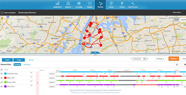
    Fleetmatics Routist is an intelligent routing optimization tool for fleet management.
    Fleetmatics Routist is an intelligent routing optimization tool for fleet management.

    “Verizon and Fleetmatics share a vision that the SaaS-based fleet management solution market is extraordinarily large, lightly penetrated, global and fragmented which can best be attacked together with a world class product offering and the largest distribution channel in the industry,” said Jim Travers, Chairman and CEO of Fleetmatics.

    “Fleetmatics brings over 37,000 customers, approximately 737,000 subscribers, a broad portfolio of industry leading products, and a team of 1,200 professionals focused on solving the critical challenges of businesses that deploy mobile workforces. We are excited to partner with Verizon in fulfilling the mission of becoming the largest mobile workforce management company in the world,” Travers added.


    The acquisition is subject to customary regulatory approvals and closing conditions, including the approval of Fleetmatics’ shareholders and the sanction of the Irish scheme of arrangement by which Verizon will acquire Fleetmatics by the Irish High Court, and is expected to close in the fourth quarter of 2016.

    PJT Partners and Wells Fargo Securities, LLC are acting as financial advisors to Verizon. Cleary Gottlieb Steen & Hamilton LLP, A&L Goodbody and Macfarlanes LLP are acting as legal advisors to Verizon. Morgan Stanley is acting as financial advisor to Fleetmatics. Goodwin Procter LLP and Maples and Calder are acting as legal advisors to Fleetmatics.

  • PNT Roundup: Remote and autonomous ships coming to high seas

    PNT Roundup: Remote and autonomous ships coming to high seas

    Remote and Autonomous Ships

    Coming Soon to the High Seas Near You

    Image courtesy of Rolls-Royce.

    The Advanced Autonomous Waterborne Applications Initiative (AAWA) published a white paper in June as part of presentations at the Autonomous Ship Technology Symposium 2016 in Amsterdam. The white paper outlines the Project’s vision of how remote and autonomous shipping will become a reality.

    Oskar Levander, Rolls-Royce vice president of Innovation – Marine, said, “This is happening. It’s not if, it’s when. The technologies needed to make remote and autonomous ships a reality exist. The AAWA project is testing sensor arrays in a range of operating and climatic conditions in Finland and has created a simulated autonomous ship control system which allows the behaviour of the complete communication system to be explored. We will see a remote controlled ship in commercial use by the end of the decade.”

    The AAWA white paper explores the research carried out to date on the business case for autonomous applications, the safety and security implications of designing and operating remotely operated ships, the legal and regulatory dimensions and the existence and readiness of a supplier network to deliver commercially applicable products in the short to medium term.

    Positioning Technologies. The proposed system draws on a range of sensors (see Figure 1) including GPS, inertial, lidar, cameras, short-range radars, and electronic charts. “When combined witha global or local positioning reference such as GNSS, and with wind sensors and inertial measurement units, the ship is able to keep its position even in rough weather conditions,” states the report. “The main question is therefore not whether the implementation of autonomous ship navigation is technically possible, but what is the combination of technologies and methods that provides the level of performance and reliability that is required for practical operation of large vessels, and at a reasonable cost.”

    The white paper draws on a wide range of expertise from academic researchers at some of Finland’s leading universities. Industry input has been provided by leading members of the maritime cluster including Rolls-Royce, Brighthouse NAPA, Deltamarin, DNV GL and Inmarsat.

    The project also has the support of shipowners and operators. The tests of sensor arrays are being carried out aboard Finferries 65-metrer double ended ferry, the Stella, which operates between Korpo and Houtskär. ESL Shipping Ltd is helping explore the implications of remote and autonomous ships for the short sea cargo sector.


    Iran Reiterates Loran Effort

    Researchers at Iran’s Malek-Ashtar University have developed a 1-megawatt transmitter with half-cycle technology for a national project announced as a replacement for GPS, which is currently employed for all positioning, navigation and timing services across the country. Given the lack of control on the GPS’s accuracy and quality and a possible outage of the system in critical conditions, the country’s defense ministry has set out to develop a local positioning system (LPS) for positioning and timing.

    Experts at the U.S.-based Resilient PNT Foundation say the description of the system make it appear to be a variant of Loran, probably similar to those operated in Russia and China. If it is such a Loran variant and if it complies with international standards, it should complement Saudi Arabia’s Loran signals in the Persian Gulf, they said.

    Iran will establish five stations with powerful transmitters in appropriate locations to provide navigation, positioning and timing services in compliance with international standards, according to the country’s defense minister.

    Iran made a similar announcement about a land-based navigation system in December 2013. The country’s military experts and technicians have reportedly logged significant progress in manufacturing a broad range of indigenous equipment.


    U.S. eLoran August demonstration

    The Wildwood, New Jersey, eLoran transmitter will continuously broadcast from July 29 through 12 p.m. Eastern time on Aug.15. Wildwood will broadcast as 8970 Master and Secondary most of the time but occasionally may operate at other rates.

  • Launchpad: OEM, UAV and survey/mapping products

    OEM

    Geodetic Antennas

    For RTK, PPP, and other precision applications

    TW6000 rendered[1]

    The VP6300 is a triple-band antenna for reception of GPS L1/L2/L5, GLONASS G1/G2/G3, BeiDou B1/B2 and Galileo E1/E5a+b (1165MHz to 1254MHz + 1560MHz to 1610MHz). The VP6200 is a dual-band antenna for reception of GPS L1/L2, GLONASS G1/G2, BeiDou B1/B2, Galileo E1 and the L-Band correction services (1195 MHz to 1254 MHz + 1525 MHz to 1610 MHz). Both antennas have been calibrated by the U.S. National Geodetic Survey and are designed for high-precision applications such as real-time kinematic, precise point positioning and other applications where precision matters. The antennas feature an available, uncommitted printed circuit board for integration of custom electronics such as precision GNSS receivers. Both antennas feature the VeraPhase technology used in the VP6000 all-band reference antenna.

    Tallysman, www.tallysman.com


    ‘Future Proof’ RTK

    For rover or base station

    Image_Altus_APS3G_external_use

    The Altus APS3G is a real-time kinematic (RTK) receiver that brings technology from scientific receivers into the field for professional surveyors. The new multi-constellation APS3G addresses major concerns about compatibility with new satellite constellations, as well as interference and jamming. Built on Septentrio’s AsteRx4 engine, the APS3G tracks all-in-view GPS, GLONASS, BeiDou, IRNSS, SBAS, Galileo and QZSS, including E6/L6 and all other signals known to be available in the medium term. The APS3G incorporates Septentrio’s AIM technology with three notch filters for in-band jamming and chirp jammer resistance, ensuring the highest possible levels of accuracy and resilience under all conditions. It provides optimum GSM signal reception, as well as a built-in advanced UHF receiver for reliable performance on longer baselines, yielding real-time 25-Hz RTK.

    Septentrio, www.septentrio.com


    GNSS Receiver

    Offshore surveys, machine control, crustal deformation

    N72_Hi-res

    CHC’s N72 GNSS series offers high-end receivers for GNSS applications including offshore surveys and machine control, national geodetic networks, crustal deformation monitoring and bathymetry. It was designed to provide all the necessary technical features required for geodetic surveying and demanding applications such as Continuously Operating Reference Stations (CORS), on-board machine control and disaster monitoring. Embedded battery supports 15 working hours without external power supply; 32-GB internal memory integrated and 1TB+ external memory supported; Eight threads of logging with circulating storage and FTP push functions; Wi-Fi, LAN, Bluetooth and serial ports for data communications; and LCD display and function buttons for direct configuration.

    CHC, www.chcnav.com


    Anti-Jam Antenna

    Suitable for airborne platforms

    GAJT-AE 34 view

    The GAJT-AE-N anti-jam antenna is designed for size- and weight-constrained applications such as small airborne and ground unmanned platforms where it is preferable to mount the antenna electronics inside the vehicle. Users can select from a variety of four-element Controlled Reception Pattern Antennas (CRPA) and cabling lengths to meet the form factor requirements of their installation. Interference mitigation is achieved by applying proprietary digital beamforming algorithms to the signals, creating dynamic nulls to give protection against narrowband and broadband interference sources. GAJT-AE-N comes in variants that protect L1 and L2 signals in wide or narrow band. The wide bandwidth version ensures future compatibility with M-code GPS.

    NovAtel, www.novatel.com


    Transportation

    GNSS Modules

    Automotive-grade positioning modules

    UB052(Fig1)

    The NEO-M8Q-01A and the NEO-M8L-01A positioning modules provide concurrent reception of GPS, GLONASS, Beidou and Galileo. The NEO-M8L-01A is suited to providing 100 percent dead-reckoning positioning coverage even in areas of weak signal such as in tunnels or multi-story car parks or those experiencing poor signal quality such as caused by multipath reflections. This module is qualified to operate in the -40 to +85 degrees temperature range. The NEO-M8Q-01 GNSS module is the first GNSS module able to operate across the extended automotive temperature range from -40 to + 105 degrees Celsius.

    u-blox, www.u-blox.com


    Connected Car Reference Platform

    Simplifies integration of advanced connectivity technologies into new vehicles

    2016-06-06-ch-qualcomm-cc-reference-platform

    The Qualcomm Connected Car Reference Platform is aimed at accelerating the adoption of advanced and complex connectivity into the next-generation of connected cars. The product is designed to maintain pace with an ever-increasing set of automotive use cases facilitated by the latest advances in 4G LTE, Wi-Fi, Bluetooth and vehicle-to-everything (V2X) communications. The platform is also designed to solve for challenges such as wireless coexistence, future-proofing and support for a large number of in-car hardware architectures. The Connected Car Reference Platform is built upon Qualcomm Technologies’ broad automotive product and technology portfolio, including quad-constellation GNSS, Snapdragon X12 and X5 LTE modems, and 2D/3D dead-reckoning location solutions, Qualcomm VIVE Wi-Fi technology, Dedicated Short Range Communications (DSRC) for V2X, Bluetooth, Bluetooth Low Energy and broadcast capabilities such as analog and digital tuner support using software-defined radio via Qualcomm tuneX chips. In addition, the platform features in-vehicle networking technologies such as Gigabit (OABR) Ethernet with Automotive Audio Bus (A2B) and Controller Area Network (CAN) interfaces.

    Qualcomm Technologies, www.qualcomm.com


    SURVEY & MAPPING

    TotalStationSurveyTotal Station App

    Connects Android device to information gathered 

    Total Station Survey helps land surveyors and civil engineers view and inspect on any Android device the information gathered by the total station. It connects to the total station using Bluetooth or a USB-serial adapter/converter cable. It can measure horizontal and vertical angle, slope and horizontal distance, and set the horizontal angle on the total station. The app is available free on Google Play.

    Systranova Software, play.google.com


    Laser and Android App

    Collect survey-grade accuracy with an Android device 

    TP300_QM3D_Cedar_TriPod_CloseUp_001

    The TruPoint 300 is a lightweight, compact point-and-shoot laser with survey-grade accuracy. It measures the distance between two remote points and has onboard solutions for volume, heights and 2D and 3D areas. Users can collect 3D measurements from a single location using a personal smart device and capture a photo of every shot taken, using LTI’s MapSmart on Android software. MapSmart combines sophisticated technology typically required to collect field data and puts it into a straightforward app for smart devices. It simplifies the mapping process by allowing users to establish an origin quickly and begin mapping in just minutes. Users can integrate location data using the GPS from a smart device or improve accuracy with an external antenna.
    Laser Technology, www.lasertech.com

    Laser Technology, www.lasertech.com


    Smartphone App

    Quick land measurements 

    GPS Fields Area

    GPS Fields Area Measure Pro is easy, intuitive, app to manage area, distance, perimeter. It enables fast area/distance marking, and ha a Smart Marker Mode for accurate pin placement. Its GPS tracking enables auto measurement while walking or driving around a boundary. Users can share an auto-generated link with boundary/selected area/ direction/route. GPS Field Area Measure useful as map measurement tool for outdoor activities, sports, range finder applications, bike tour planning, or run tour planning, explore golf area, land survey, golf distance meter, field pasture area measure, garden and farm work and planning, area records, construction, agricultural fencing, solar panel installation – roof area estimation, trip planning.

    Studio Noframe, play.google.com


    Dedicated 3D Tablet

    Capture and review 3D images in the field  

    3DTablet

    The EyesMap tablet is a versatile instrument for modeling 3D scenes indoors and outdoors. It provides results while working in the field with real-time measurements. The tablet has a stereocamera, depth sensor scanner, GPS and inertial measureent unit. It also supports external cameras and other topographic instruments. Applications include crime scene investigation, archaeology and architecture documentation, as-built measurements and inspections, industrial and civil maintenance.

    eCapture, www.ecapture.es


    Handheld Collector

    Entry-level GNSS device for GIS 

    TDC100_FrontThe TDC100 handheld data collector is an entry-level GNSS device for a variety of geographic information system (GIS) applications. It combines both smartphone and ruggedized data collection capabilities in a single, mobile device. The Android-based TDC100 can run commercially available or in-house developed applications on a professional, IP-67 ruggedized platform with a sunlight readable display and user replaceable batteries. The built-in GNSS receiver also provides real-time accuracy. It supports GPS, GLONASS and BeiDou, as well as satellite-based augmentation system (SBAS) capabilities.

    Trimble, www.trimble.com


    UAV

    RedHen-UAVreconnaissanceReconnaissance Kit

    Situational awareness for disaster relief

    The Digital Mapping Reconnaissance Toolkit (DMRT) provides real-time reconnaissance for disaster relief and other time-sensitive situations. . It is a custom configuration of cameras, laser rangefinder, GPS unit and software all linked through the Red Hen VMS-333 multiplexing system. Users can create up-to-date orthomosaic maps and 3D models, as well as geotag reference points in impacted areas without a time lag. Users can create search patterns and map with situational awareness. Both modular aerial and land-based solutions are available

    Red Hen Systems, www.redhensystems.com


    UAV Backpack

    Intelligent Obstacle Navigation

    Yuneec Typhoon H with Intel RealSense Technology (PRNewsFoto/Yuneec International)

    The Typhoon H UAV with Intel RealSense Technology comes with a factory installed Intel RealSense R200 Camera and quadcore Intel Atom processor, an ST16 controller with a Wizard controller for dual operator mode, two batteries and extra propellers, all packed in a custom designed backpack. RealSense Technology enables Typhoon H to fly autonomously, intelligently navigating around objects. The Intel RealSense R200 Camera and the Atom processor work seamlessly with the flight-control firmware to add intelligent obstacle navigation. With a combination of specialized cameras and sensors, this Intel system maps and learns its environment in 3D, recognizing each obstacle, planning an alternative route, and safely navigating around it — an advancement over ultrasonic collision prevention, which automatically stops short of obstacles but cannot model the environment or intelligently reroute around obstacles. The module also adds downward facing sensors to improve stability, enabling flight indoors or outdoors close to the ground, even with poor GPS reception.

     Yuneec International, www.yuneec.com


    Intelligence Platform

    Insight for complex missions

    Advanced alerting

    Mission Insight provides UAS operators in deployed situations with a common operating picture in a customized graphical interface. The commercial off-the-shelf application processes and analyzes large streams of data from disparate sources in real-time. It ensures real-time, in-depth data access for mission-critical events even in remote environments or low-bandwidth situations. Complex data filtering, advanced processing and timing techniques enable Mission Insight to prioritize data and allow transmission as low as 2400 baud. The complete information management solution —including archival and replay capabilities in addition to the correlation, fusion and analytical tools — aid in training, post-operation analysis, incident investigation and review of operational effectiveness.

    Simulyze, www.simulyze.com


    Multi-Spectral Camera

    Situational awareness for disaster relief

    Sensefly_Camera_2

    Sequoia is a small, light multispectral UAS sensor that captures images of crops across four highly defined, visible and non-visible spectral bands, plus RGB imagery. Sequoia is fully compatible with the eBee Ag and other eBee platforms via senseFly’s proprietary Integration Kit. It has four 1.2 megapixel sensors (near-infrared, red-edge, red and green) plus one 16 megapixel RGB sensor, providing multispectral and RGB imagery from a single flight. An upward-facing Sunshine Sensor automatically calibrates Sequoia’s multispectral sensors for accurate imagery, whatever the light conditions. The camera unit can be configured over Wi-Fi and has 64-GB of built-in storage; the Sunshine Sensor has GPS, an IMU, a magnetometer and SD card slot

    senseFly, www.sensefly.com


  • Esri and Leica partner to offer GIS/GPS grants to governments

    Geographic information system (GIS) provider Esri has partnered with Swiss-based spatial measurement instrument manufacturer Leica Geosystems to encourage innovation of mobile field data collection in government by offering grants totaling $143,250 in goods and services.

    Projects should combine GIS and GPS.

    esri-logo

    Known as the Smart Communities Innovation Challenge, 10 governments that submit detailed project proposals demonstrating increased efficiencies in collecting data for decision support or improved productivity in delivering governmental services will be selected to receive a grant.

    Project proposals will be accepted from Aug. 15, 2016, until the official submission deadline at 5 p.m. (Pacific daylight time) on Oct. 14, 2016. Grant recipients will be announced on Oct. 31.

    leica_logoTo be entered for consideration, proposal submissions must be uploaded in conjunction with the organization’s identifying information through a form on the Smart Communities Innovation Challenge landing page.

    So long as operations are based in the United States, any government or department, whether municipal, regional, special districts, state, city, county, or otherwise, is qualified to receive a grant.

    To be selected, it is necessary that a project confirm the value of combining GIS and Global Positioning System (GPS) technologies for data collection, optimizing workloads, and providing real-time information that supports field mobility. Proposal reviewers will look for ideas that support complete workflows extended to back-office processes such as operational dashboards.

    Priority will be given to projects that tie GIS and GPS to daily workloads, influence sharing of geographically enabled data across multiple jurisdictions or interdepartmental ventures, and clearly convey a perceived benefit or return on investment.

    The intent of the joint program is to supply governments with the tools to succeed as they implement progressive methods to streamline workflows. By providing technology, training, and technical support grants, Esri and Leica aim to inspire legislative bodies to devise transformational approaches to improving the efficiency of mobile fieldworkers.

    As innovative ideas from the government community are brought forward for solving real-world problems, the best applications will be those of universal appeal and the ability to be shared between governments through an open exchange hub.

    The challenge’s grant winners will be thought-leading governments that have plans in place to jump-start projects such as facility inspections, emergency reporting, asset inventory, environmental management and monitoring, efficient employee routing, code enforcement, population and housing enumeration, mosquito abatement and/or sign inventory.

    To learn more about the Smart Communities Innovation Challenge and other grants sponsored by Esri, visit go.esri.com/pr-mobilegrant.

  • Trimble acquires Axio-Net GmbH to reinforce European presence

    Trimble acquires Axio-Net GmbH to reinforce European presence

    Trimble has acquired Axio-Net GmbH from Airbus Defence and Space. Based in Hannover, Germany, Axio-Net is a provider of GNSS corrections and professional data services serving Germany, the United Kingdom and Benelux. Financial terms of the transaction were not disclosed.

    AXIO-NET_logoAxio-Net, founded in 2008, delivers both real-time and post-processed network real-time kinematic (RTK) solutions to a broad range of users including surveyors, GIS professionals and farmers. In addition to traditional correction services, Axio-Net performs a variety of data-based professional services for the geospatial market, including coordinate transformation services as well as network set-up, configuration and operations consulting.

    “Our philosophies are highly complementary and together, we will extend Trimble’s position as a global leader of GNSS corrections,” said Patricia Boothe, general manager of Trimble’s Advanced Positioning Division. “We are committed to supporting Axio-Net’s brand-agnostic position, while we leverage their experience with professional services, not only in traditional markets such as geospatial and agriculture, but in emerging high-accuracy GNSS markets such as automotive.”


  • Oshkosh gives nod to GPS Networking on light-tactical defense contract

    Oshkosh Defense, a subsidiary of Oshkosh Corporation, has approved GPS Networking as a supplier on the Joint Light Tactical Vehicle (JLTV) Program.

    After going through rigorous qualification testing and thorough vetting, GPS Networking was approved to supply GPS Networking products for the JLTV. During the contract, which includes both Low Rate Initial Production (LRIP) and Full Rate Production (FRP), Oshkosh expects to deliver approximately 17,000 vehicles and sustainment services.

    The JLTV Program is a U.S. Department of Defense (DoD) response to unconventional threats such as IEDs and other explosives, pointing to a need for lightweight, protected vehicles.

    The Oshkosh JLTV solution uses parts and services of more than 350 suppliers in more than 30 states.

    GPS Networking, based in Colorado, supplies products for GPS signal distribution and acquisition. It has been a major supplier for cellular infrastructure, worldwide military applications and all facets of public safety, including but not limited to signal acquisition. GPS Networking is Certified ISO 9001:2008 and is currently preparing for ISO 9001:2015. Its products are available with military certification to Military Standard 810F, EMI certified and have CE approval.

  • Eos offers sub-meter and RTK for Esri’s Collector 10.4 for iOS

    Eos offers sub-meter and RTK for Esri’s Collector 10.4 for iOS

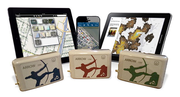
    Eos Positioning Systems has announced that its Arrow series of GNSS receivers is compatible with Esri’s Collector for ArcGIS running on iPads and iPhones. The Arrow receivers have been tested and certified as high-accuracy GNSS receivers compatible with Collector 10.4.0 for iOS.

    ipad-iphone-samsung-arrow-O

    The full range of Arrow GNSS receivers from sub-meter to decimeter to centimeter RTK accuracy all work flawlessly with Collector for ArcGIS running on all iPhones and iPads running iOS 8.x or later, according to the company. GNSS metadata — including estimated accuracy, correction status, correction age and number of satellites used — is displayed in real-time in Collector, so the user can monitor data quality in the field.

    “We worked closely with Esri during their development of Collector to ensure the best high-accuracy GNSS user experience with the Arrow GNSS series receivers, and I think we’ve achieved that,” said Eos CTO Jean-Yves Lauture. “Whether it’s our Arrow Lite, Arrow 100 or Arrow 200 receiver, they all work smoothly with Collector for iOS for sub-meter, sub-foot, decimeter and centimeter accuracy.”

    Eos Tools Pro.
    Eos Tools Pro.

    As a companion software to Collector, Eos offers a free iOS app called Eos Tools Pro that allows the user to connect to an RTK network and to set alarms for estimated accuracy, HDOP, correction age and others. If a threshold is exceeded (such as estimated accuracy greater than 10 centimeters), an alarm sounds on the iPhone or iPad to alert the user.

    “We have tested Arrow receivers and confirmed that Collector for ArcGIS (iOS) is completely compatible with the Arrow GNSS series receivers,” said Esri Product Manager Jeff Shaner. “The tight integration between Collector and Arrow GNSS receivers really enhances the high-accuracy user experience, and during our recent beta program, customers like Le-Ax Water District have shared their success using Collector and the Arrow receivers.”

    Collector for ArcGIS (iOS) is a geographic information systems (GIS) data collection program that runs on iPhone and iPads. It records data directly, in real time to ArcGIS Online, Portal for ArcGIS and ArcGIS Server at sub-meter, decimeter and centimeter accuracies when using the Arrow GNSS receivers. No post-processing or other specialty software is required.

    Collector 10.4.0 can be configured to automatically transform between horizontal datums on-the-fly, so no matter which datum the user’s GNSS data is referenced to, it can be configured to be compatible with the user’s geodatabase, and Esri provides scripts for transforming between vertical datums when back in the office.

    Eos GNSS Tools and Arrow receivers are targeted at high-accuracy applications such as GIS; environmental monitoring; agriculture; electric, gas, water utilities; surveying; machine control; and federal, state and local government.

  • Decawave ships 1 million ultra-wideband micro-location chips

    Decawave ships 1 million ultra-wideband micro-location chips

    Decawave-DW1000Chip4-WDecawave, which specializes in precise location and connectivity applications, has reached a milestone for its micro-location, impulse radio ultra-wideband (IR-UWB) technology, surpassing one million Decawave chips shipped.

    The chip’s popularity reflects the increasing demand for accurate micro-location solutions from end users and customers within Internet of Things (IoT), consumer and industrial markets. According to the company, Decawave has a target to reach five million units shipped in the course of 2017.

    Decawave offers IR-UWB wireless technology for precise location and connectivity applications that can identify the specific location of any object or person within a guaranteed indoor location accuracy of 10 centimeters.

    IR-UWB is becoming a key factor in the IoT market and is impacting how developers are taking devices and smart applications to the next level of context awareness, Decawave said in a press release.

    The increase in demand for accurate location-based applications is evident across sectors including consumer markets such as connected homes, phone accessories, drones and sports analytics; industrial with connected buildings, factory automation and healthcare.

    Decawave technology also will be embedded in cars in 2017.

    The industrial market has been the first market to leverage Decawave’s technology and several Decawave customer solutions are already in the field. Decawave has 15 industrial partners that can deliver software, hardware or turn-key systems to end customers.

    “The market for next-generation indoor location technologies with improved accuracy is beginning to advance with solid use cases and adoption. UWB is clearly carving out its space, with ABI Research forecasting strong growth across a range of verticals,” said Patrick Connolly, Principal analyst at ABI Research. “The market opportunity is quite large and companies like Decawave that are leading the charge in UWB are well positioned to experience continued growth.”

    Consumer products. The consumer products —  some of which were presented at the Consumer Electronics Show (CES) in January — are starting to ship now. For instance, Pixie tags allow customers to accurately locate, protect and organize their valuables.

    Also at CES, Decawave highlighted ShotTracker, developed with sporting-goods company Spalding, for multi-player basketball tracking. The chip was also featured in Jaguar’s connected car demonstration.

    ShotTracker captures every player statistic for multiple players in real time.
    ShotTracker captures every basketball player’s statistic for multiple players in real time.

    In the consumer segment, there will also be opportunities in access control, remote controls, connected light, home robot and trusted-zones applications that leverage IR-UWB accuracy, reliability and immunity to relay attack schemes to grant or deny access to wireless-networks and connected devices.

    “Two years after launching the technology, Decawave continues to gain traction with 1,800 customers across 68 countries using Decawave’s IR-UWB and an extra 70 to 80 new customers each month,” said Ciaran Connell, CEO of Decawave. “This is phenomenal and shows our commitment as well as market interest and future demand. We’re thrilled that UWB is finally seeing market momentum. We know its potential and now our customers are experiencing it as well.”

    Decawave’s partner Quantitec showed its RTLS indoor positioning at Nokia’s booth at Mobile World Congress and at the Bosch Connected World where it was featured in the company’s advanced localization technology, as a key element of a Track and Trace solution.