Rohde & Schwarz’s FSW85 high-end signal and spectrum analyzer, including an analysis option for FMCW chirp signals, is suitable for testing advanced driver assistance systems (ADAS). It analyzes automotive radar sensors designed for designated frequency bands around 24 gigahertz and 79 gigahertz.
It can cover the frequency range from 2 gigahertz to 85 gigahertz in a single sweep. Its optional analysis bandwidth of up to 2 gigahertz makes it possible to demodulate and thoroughly analyze even extremely broadband signals.
R&S also offers an eCall test system consisting of the R&S CMW500 and the GNSS-capable R&S SMBV100A vector signal generator, a hardware-in-the-loop solution for standard-compliant end-to-end tests for wireless communications and GNSS-capable components in in-vehicle systems.
Chaminda Basnayake, Principal Engineer, V2X Systems, Renesas Electronics
In the basic V2X concept of operation, everybody will be talking to each other, will be aware of each other. Any car will be broadcasting BSMs, pedestrian or personal devices will be broadcasting an equivalent message, called personal safety messages (PSM), and then all the control devices like traffic control will broadcast signal-based timing information, SPAT messages, intersection maps and GPS correction data.
The expectation in the system design is that all vehicles will provide position information and location accuracy, and the vehicle should be able to get this from itself and from others.
The idea is that every vehicle should be able to relatively position everyone else, and then with the onboard device, the vehicle should be able to position itself with respect to the roadway.
A lot of applications are out there. A good source of further information on these is put together by the Connected Vehicle Reference Implementation Architecture, a U.S. Department of Transportation initiative.
Connected Car Gateway for applications such as emergency calling, telematics, infotainment data distribution and usage-based insurance. (Image: u-blox)
John Kenney, Director and Principal Researcher, Network Division, Toyota InfoTechnology Center
A couple of issues are hot today with regard to spectrum and how we’re going to use it: what kinds of technology to use to support V2X, in the United States and around the world, and also whether that spectrum can be shared by other technologies for other purposes.
V2X is an inherently ad hoc network, and that makes evolution across generations a much more challenging task than we are used to seeing in the cellular environment.
Dedicated Short-Range Communication (DSRC) technology is now mature, and it’s entering the deployment phase. The cellular V2X technology that’s in the initial standardization is interesting; it offers benefits by complementing DSRC, but we don’t want to see it positioned as a competitor. The auto industry wants to remove uncertainty (regarding spectrum sharing) but only in a way that does not threaten DSRC’s safety-of-life mission.
Nikolaos Papadopoulos, President, u-blox America
The adjacent figure shows an in-vehicle module for emergency calling, other positioning applications and infotainment. The blue boxes show the components that we supply: the GNSS with three-dimensional dead reckoning, and in the future with lane-level accuracy, the TOBY 4000 with the customer application, as well as Wi-Fi, Bluetooth and near-field communications.
I have shown examples in this webinar where we can clearly identify lane changes with a combination of GNSS technologies.
We very much encourage both Tier Ones and OEMs to keep the cellular technology, the short-range communication technology, and the GNSS positioning technology separate. The advances in GNSS and positioning for autonomous vehicles are truly extraordinary, and can only be done in the separate GNSS technology.
How to put the car on a nap? Positioning technology options. (Image: Renesas Electronics)
Roger Berg, Vice President, Wireless Technologies, DENSO North American R&D Laboratories
The video example that I showed here, of advance warning of a braking car hidden from your line of sight ahead of you, used a Toyota vehicle, a u-blox positional element, and a Renesas V2V component.
We’ve learned through experience that one company can’t do it all. This is an ecosystem that requires connectivity and cooperation. No longer is a vehicle its own entity; it does not operate separate from infrastructure and other road users. And finally, we can’t necessarily predict how connected and automated drivers interact with so-called regular vehicles, those controlled by human drivers. It’s going to take a lot of collaboration between industry, academia and government to be effective.
The ancient city-kingdom of Kourion on the southwestern coast of Cyprus can now be “seen” by those with impaired vision.
Kourion, part of the UNESCO World Heritage Site of Paphos, was once an important urban center. While most of the archaeological remains — including several buildings with well conserved floor mosaics — date to the Roman and Early Byzantine periods, the most ancient finds connect to settlements and tombs of the Ceramic Neolithic period (circa 5500-4000 BCE).
A tactile map: In summer 2015, sections of the virtual 3D model, including the amphitheater, were printed in 3D and displayed in the visitor center with Braille explanations, providing an interactive history to those with visual impairments.
British drone manufacturer QuestUAV, in cooperation with the Cyprus University of Technology, acquired high-resolution aerial images of Kourion Archaeological Park with a surveying drone, and then created a virtual 3D model from the images with Pix4Dmapper Pro.
The QuestUAV team (a pilot and laptop commander) flew over 100 hectare of the archaeological park at 400 feet with a Q-200 Surveyor drone equipped with a Sony A6000 camera and a 16mm wide-angle lens, taking 330 aerial photographs during a 20-minute, fully autonomous flight.
The automatic camera trigger and the gimbaled camera system enabled acquisition of pin-sharp pictures, even at wind speeds of up to 40 kilometers per hour.
The images have a ground sampling distance of 2.5 centimeters with an overlap of 80 percent in flight direction and 65 percent sidelap. During the flight, the Q-200 Surveyor recorded the GPS coordinates of each camera position in a log file, allowing for image geo-location.
The entire survey took no longer than an afternoon.
Komatsu America Corp., a global heavy equipment manufacturer, is offering its first fully radio controlled machine with Komatsu’s intelligent Machine Control (iMC) technology.
The 155AXi-8 Radio Control dozer is part of a line of next-generation machines operating semi autonomously with intelligent machine control.
The D155AXi-8 is designed for applications where customers may want to remove the operator from the machine and still maintain high levels of efficiency and productivity. The dozer uses Komatsu’s automated rough-cut-to-finish-grade technology.
For many operators, the ability to feel machine response to blade load is important to effective dozing. To compensate, the D155AXi-8 RC dozer uses iMC, which automates operation whether dozing heavy material or during fine grading. iMC can sense and control the load the blade carries by using stroke-sensing hydraulic cylinders and an inertial measuring unit.
It can optimize the start of the cut, lowering the blade to the correct grade, then raising the blade when the system senses that a maximum load.
Equipping the machine with remote control was done to accommodate quarry, pit and other applications where concerns over high water or extremely rocky conditions may put the operator in harm’s way or give the operator an uncomfortably rough ride.
The Komatsu 155AXi-8 Radio Control dozer is one in a line of next-generation machines operating semi-autonomously with intelligent machine control.
Intellgent machine control
Base station corrections fix satellite errors and usemachine settings to generate an accurate current position of the blade, which is compared to the 3D model of the project.
An automatic hydraulic interface moves the blade to the exact design grade.
The cab displays a simple interface to provide grading information, including cut or fill values.
Benefits include faster grading operations, fewer passes, less rework and lower machine operating costs.
Secondary receiver uses eLoran to back up GPS time
Spectracom has been selected to provide Interference, Detection and Mitigation (IDM) capability to its SecureSync precision time and frequency reference system to support Rohde & Schwarz Benelux B.V. and the Netherlands Ministry of Defence for secure long-range military communications systems.
The upgrade, which is based on a secondary receiver that extracts precision timing signals from the eLoran system when GPS signals are not available, will increase the reliability of the overall communication system by further enhancing the resiliency of the precision timing core.
As part of its expanding set of resilient PNT solutions, Spectracom systems synchronize to a variety of precision references whenever and wherever available.
In this deployment, signals from the eLoran system are constantly monitored and act as the primary reference when GNSS signals are not available due to interference or jamming. This new capability supports the goal of a sustainable and reliable network for ongoing global operations.
The modularity of the SecureSync precision time and frequency platform allows customers and integrators to easily and incrementally increase system capabilities, such as multiple reference signals, as they become available.
Integrated with images and dense distance measurements from a range camera using active illumination, inertial navigation produces real-time results on a tablet computer. Experiments demonstrate that the system provides good positioning and mapping performance in a range of indoor environments, including darkness and smoke.
Soldier with prototype system mounted on tactical vest.
Positioning and mapping abilities for indoor environments can speed search and rescue, keep firefighters from getting lost, and help a commander track soldiers searching a building. Accurate results from these environments increase personnel safety in unknown, dangerous environments and can also facilitate remote control of unmanned ground vehicles (UGVs).
A new iteration in the Chameleon family of positioning systems that we have developed, the Tiger Chameleon, combines an inertial measurement unit (IMU) with an active camera that measures distances using modulated laser light. This type of camera provides dense and accurate distance measurements, and has the added advantage of working well in darkness.
The main goal of the Chameleon systems is to provide soldiers and first responders with position information and approximate overview maps, preferably without affecting their operating procedure. The Tiger Chameleon does not require any infrastructure, such as visual markers or radio beacons. Positioning and mapping results are computed in real time based on data from the IMU and the active camera, and wirelessly transmitted to a visualization interface running on a tablet computer or smartphone.
Sensors and Hardware
In initial experiments, the Tiger Chameleon’s components are enclosed in a wooden box which can be mounted on a soldier’s tactical vest. FIGURE 1gives a schematic overview.
FIGURE 1. Schematic overview of how the components are connected.
Image Sensor. The image sensor includes two cameras: one high-resolution visual camera and one lower-resolution depth sensor. The latter uses a modulated near-infrared (NIR) light source and a special type of sensor to measure distance. Essentially, each pixel is divided into two halves, one of which integrates incoming light when the light source is turned on, while the other integrates light when it is turned off. If the light hitting a pixel has bounced off an object located close to the sensor, almost all light will be integrated by the first half of the pixel. If the object is moved further away, it will take longer for the light to return, and hence more light will be integrated by the second half of the pixel.
In addition to measuring the depth of the scene, the NIR camera provides an intensity image where the value of each pixel is determined by the total amount of light hitting the two pixel halves. The intensity image is similar to an ordinary visual image. Unlike an image from a passive camera, however, it is largely independent of ambient light, since it mostly measures reflected light from the illuminator. Hence, both the intensity and the depth images are available even in completely dark or obscured environments. Coming from the same sensor, the intensity and depth images are perfectly registered to each other. Images are produced at 30 Hz.
The high-resolution visual camera is not used by this prototype.
Inertial Sensor. The IMU provides calibrated measurements of acceleration and angular velocity at 400 Hz. The sensor itself does not perform any inertial navigation or attitude estimation. Since we fuse the inertial data with image-based features for navigation, however, the basic acceleration and angular velocity measurements are more useful in our application than pre-filtered position or orientation estimates. The sensor measures acceleration up to 5 g, and angular velocity up to 1,000 degrees/ second, since relatively high-dynamic motion is common in the intended application. The IMU also contains a magnetometer and a barometer, but these are not used since air pressure and magnetic fields are not always reliable for navigation indoors.
Algorithms
The positioning algorithm is based on EKF-SLAM, simultaneous localization and mapping (SLAM) implemented as an extended Kalman filter (EKF). The EKF fuses data from the IMU (three-dimensional accelerations and angular velocities) with image data, according to the uncertainties of the different types of data. It tracks the system state, composed of the position, velocity and orientation of the system, the IMU biases (slowly varying offsets in the acceleration and angular velocity measurements), and the positions of a number of landmarks in the images.
The landmarks are points observed in the images, which are used for navigation. These are chosen to be points which are recognizable, well-defined and stationary. This essentially means that it should be easy to recognize a landmark when it appears in a new image, and that the image coordinates of a landmark should be stable in both the horizontal and vertical directions. Thus, corner points are good candidates for landmarks, while line structures in an image are not. The world coordinates of a landmark should not change over time.
Theoretically, it would be possible to navigate using only IMU data. The system orientation would then be obtained by integrating the angular velocities, while the acceleration (after removing the effect of gravity) would be integrated to obtain the velocity, and double-integrated to obtain the position. Due to the high bias variability and noise of micro-electro-mechanical systems (MEMS) IMUs — the only type sufficiently small, lightweight and inexpensive for use by soldiers or firefighters — this only works for a few seconds before the accumulated error grows to an unacceptable level.
In theory, it would also be possible to navigate using only landmarks extracted from the image sequence. This, however, is also problematic in practice. If the system moves too rapidly, successive images may not share any landmarks at all. Additionally, no landmarks are found in featureless environments. This causes image-only navigation to fail in many realistic scenarios.
By fusing the inertial data with landmark observations, we alleviate most of these problems. While the IMU provides good short-term performance, the image data provides long- term stability. Hence, the IMU can overcome short periods with few or no landmarks, while the image data limits the error growth of the system (assuming that the periods without landmarks are not too long).
FIGURE 2. Overview of the algorithm.
Algorithm Flow. In the data fusion FIGURE 2, potential landmarks are found in an intensity image from the NIR camera, by identifying points that can be well localized. The potential landmarks are found by using an interest-point detector. The visual appearance of a point is represented using the SIFT descriptor. The distance to each potential landmark is determined by using the depth image. Potential landmarks are matched to landmarks that are already tracked by the system, based on a combination of their visual appearance and their coordinates (the spatial distance between the observed points and the predicted image coordinates of the tracked points, and the difference between the predicted and the observed distance to the points).
IMU data is used to predict where tracked points should appear. Pure inertial navigation is relatively accurate in the time interval between successive frames (approximately 30 images per second are processed). Observed points, which match tracked points, are used to update the estimated state (position, velocity and so on). Tracking is started for observed points, which do not match any tracked points unless a predetermined number (30 in the current implementation) of points are already tracked. Points that are tracked but not observed in a number of consecutive image pairs are removed from the point tracker.
Each depth image corresponds to a local point cloud, where points lie on the surfaces of objects in the scene observed by the camera. The intensity of each point can be obtained from the corresponding intensity image. Since the position and orientation of the system are estimated by the SLAM algorithm, these local point clouds can be transformed into a common coordinate system, thereby creating a large point cloud representing the entire environment along the trajectory of the system. This point cloud can either be used as a three dimensional model, or projected onto a horizontal plane for an overview map.
Implementation
To accurately predict where tracked landmarks will appear in a new image, it is important to synchronize the image stream and the inertial data. While the IMU handles this well (it can either trigger, or timestamp the trigger pulse from, a camera), synchronization is potentially difficult when working with consumer hardware such as the the one selected for this prototype. However, while the camera cannot be triggered externally, it does perform internal synchronization between the NIR and the visual cameras, which both run at 30 Hz. (It is unknown to us which camera triggers the other, or if there is a third piece of hardware which triggers both cameras.) Using an oscilloscope, we found that a pulse train at 30 Hz can be accessed at a solder point inside the camera.
This 30 Hz signal is active whenever the camera is powered. It is therefore not possible to synchronize the camera to the IMU using only this signal, since it only indicates that an arbitrary image was acquired at the time of each pulse. To synchronize the sensors, we need to know exactly when each specific image was acquired. Thus, a synchronization pulse, which is only transmitted when image acquisition is enabled, is needed. In addition to the 30-Hz pulse train, a signal that is high only when the cameras are active can also be found inside the camera. We perform a logical AND to combine these signals into the desired synchronization pulse.
We obtain the timestamp of each image from the IMU by connecting the combined synchronization signal to its synchronization input. There is a small delay between the first pulse in the combined signal and the time when the first image is acquired. This was measured by recording inertial data and images while first keeping the system stationary, and then rotating it quickly. Manual inspection of the image sequence and the angular velocities reveals that the delay is approximately 8 intra-frame intervals (0.267 s).
Software. The recording and analysis software are written in C++, and run in real time under Linux. It makes heavy use of multi-threading in order to optimize the computational performance of the algorithms.
The software is divided into two subsystems: one that communicates with the sensors, and one that performs the image analysis and SLAM computations. These subsystems communicate using the Robot Operating System (ROS). There is also a subsystem (or “node” in ROS terminology) for playing back previously recorded data. The playback node publishes the same type of messages as the sensor node, and these nodes can therefore be used interchangeably.
FIGURE 3. Overview of the analysis node. Blue boxes represent threads, while red boxes are queues. Purple boxes are other software components, and the orange and the red/green boxes represent the sensors. Orange, red and green lines represent data from the respective sensors. Black lines represent data based on more than one sensor.
FIGURE 3 shows how data flows through the analysis node. Queues buffer data between the different threads. Incoming images from the recording or playback node are initially put in the image queues for feature extraction. After feature extraction (where the depth image is used to determine the distance to each observed landmark), the resulting image features are stored in the potential landmarks queue. The features are then processed by the EKF-SLAM thread, which also reads from the IMU data queue. The resulting pose estimates (positions and orientations) are sent to the communication module, where they are transmitted to the visualization device. In parallel with this, images are also processed by the rectification and mapping threads, where they are paired with poses from the SLAM algorithm to create map data. The map data is also sent to the communication module. A number of efficient libraries exist for low-level image processing, and also for the linear algebra computations needed by the EKF. The following libraries are used:
VLFeat for finding landmarks and extracting SIFT features
OpenCV for image rectification
Armadillo for high-level math operations
ROS for communication between the subsystems
A modified version of IAI Kinect2 for ROS communication with the sensor
A slightly modified version of Libfreenect for low-level communication with the sensor.
Evaluation
The prototype has been evaluated in a number of experiments, in cooperation with soldiers and first responders. Three experiments are reported here. All were performed during soldier or smoke-diver training. Mapping results in the figures are presented along with estimated soldier and smoke-diver trajectories (bluegreen lines) from the positioning system. The results are evaluated based on the mapping, since the ground truth trajectories are unknown. Positioning is still evaluated implicitly, as inaccurate positioning would cause poor mapping performance such as double or skewed walls, since the mapping is based on estimated camera positions and orientations.
Searching for Biological Hazards. Collection of evidence at a crime scene is commonly performed using a camera, taking numerous pictures of the scene from different positions at different angles and distances. To keep track of all images and where they were captured is cumbersome work, which can easily be automated by integrating the camera with a positioning system.
Several variations of this experiment were performed, all in cooperation with soldiers from the Swedish Armed Forces National CBRN Defence Centre. The main task was to document different areas in the building, to be able to handle any encountered dangerous biological objects in a safe way, and to preserve evidence for later use. If a dangerous object is found, the mapping result from the system could be used to plan how the object should be taken care of and what exit path the soldiers could use to minimize the time being exposed to a dangerous environment.
FIGURE 4. Map estimated by the prototype positioning and mapping system while two soldiers searched for biological hazards. The trajectory is also shown. The grid spacing is two meters.
The photo above an image from the NIR sensor in the prototype system, captured in the building while two soldiers searched for biological hazards. A map estimated by the prototype system appears in FIGURE 4.
For evaluation of the mapping performance, a part of this building was also measured using a highly accurate scanning laser system. FIGURE 5 shows the point clouds from both the Tiger Chameleon (black) and the scanning laser (white). Locally (within a room), the errors are less than 5 centimeters. Over larger distances, heading drift causes larger errors, which are visible as slightly misaligned walls. In this case, there are no significant errors. (The structures that are only visible in the laser scanner data are parts of the ceiling and its supporting beams, which were never observed by the positioning system.)
FIGURE 5. Map produced by the Tiger Chameleon (black) overlaid on reference data (white).
Searching a Building. A group of eight soldiers searched and cleared a part of a building. This required them to move more quickly than in the first experiment, since the building could not be assumed to be safe. Additionally, one or several soldiers often appears in the field of view of the positioning system. We requested the soldier carrying the system to avoid walking too close behind another soldier, to avoid covering the entire field of view. Apart from this, the soldiers were asked to act as they normally would during the exercise.
FIGURE 6 Map estimated while eight soldiers cleared a building.
Positioning and mapping results are shown in FIGURE 6. The map is slightly distorted due to errors in the estimated heading, but still good enough to understand the building layout. The distortion is visible as double walls in the top part of the figure. We believe that most of the errors were caused by the system not being entirely stationary during the sensor initialization at the start of the experiment. No reference map is available for this location. We also performed experiments where the soldiers fired their weapons near the positioning system. This affects the IMU, severely degrading the measurements of acceleration and angular velocity. Hence, the positioning system was not able to present correct position or mapping estimates in these cases.
Smoke-Diver Searching a Building. The smoke-diver experiments indicated how the positioning system performs when used in a smoke-filled environment. During the experiments, the system was exposed to different levels of smoke.
FIGURE 7. Map estimated while a smoke-diver searched a (partly) smoke-filled building. The trajectory is also shown.
Positioning and mapping results from the experiment are shown in FIGURE 7, while FIGURE 8shows the result from the Tiger Chameleon (black) overlaid on reference data from the laser scanner (white). The estimated map is in good agreement with the reference map data, although a heading error affects some walls (bottom right).
All smoke densities affect the image quality from the NIR sensor, since the active illumination is reflected by the smoke particles. In light smoke, the main effect is that the smoke appears as spurious points in the point clouds, eventually ending up in the map, while positioning performance is not significantly affected. Most spurious points were removed by adding the constraint that points very close to the camera are not added to the map, although smoke still causes more interior points to be visible in Figure 7 than in the other maps. The effect on the positioning system increases with the smoke density. In thick smoke, most illumination is reflected, effectively rendering positioning impossible using this type of image sensor.
Discussion
FIGURE 8. Maps from the experiment in smoke. The map produced by the Tiger Chameleon (black) is overlaid on reference data (white).
The current positioning algorithm works well, but over longer experiments its position estimate slowly drifts away from the true position. This is caused by both the inertial sensors and the landmark-based positioning updating the current position estimate only relative to recent estimates. Since landmarks are discarded after not being observed for a short time, no loop closures ever occur. Saving landmarks could solve this in specific scenarios, where landmarks are re-observed after long times, but doing so would increase the computational complexity considerably. Additionally, for landmark-based loop closure to work well, the landmarks would need to be reobserved from approximately the same position, further limiting the scenarios where this could be expected to work well. Ongoing work aims instead at closing loops by recognizing the scene geometry, as represented by the point-cloud models.
When using active illumination, the mapping performance does not depend on texture on walls and other surfaces. This is an advantage compared to passive stereo cameras. Further, active illumination enables positioning and mapping in darkness.
Comparison to Other Systems. The prototype system was not constructed with the purpose of creating high accuracy models of small, detailed environments. Rather, the purpose was to enable soldiers to create approximate maps of entire buildings with minimal impact on their operating procedure. Detailed reconstruction is handled better by other systems, but these have the disadvantage of requiring the user to survey the environment systematically, adapting his or her work methods to the sensor.
SWaP-C and Hardware. Size, weight, power and cost (SWaP-C) are constant issues for soldier equipment. Ideally, the equipment should be disposable: cheap enough to throw away after being used just once, or fit into some type of disposable container.
Since this is a prototype system built for research and demonstration purposes, components with convenient electrical and programming interfaces have been selected. Therefore, the system is considerably larger than a final end-user product would be. In such a product, sensors and computation hardware with similar performance, but considerable smaller size, lower weight and lower power consumption, would be selected instead. Such components are commercially available.
Outdoor/Indoor Use. Though this positioning system is primarily designed for indoor use, seamless transition between indoor and outdoor environments is desired. Ongoing work aims at integrating a GPS receiver to achieve this. Adding GPS would also enable positioning in a georeferenced coordinate system; currently, all results are presented in a local coordinate system defined by the start position and orientation. This requires an algorithm for making robust decisions regarding when GPS measurements should be considered reliable.
Visualization Interface. The visualization interface currently runs on a tablet computer, and is therefore most useful to a commander or group leader who remotely tracks the soldier or firefighter. By adapting the interface to the smaller screen of a smartphone, it would be possible to also give the user access to position and map information.
An important advantage of automatic mapping, according to several users, is the ability to detect hidden spaces in buildings. In certain types of operations, the ability to document a building before leaving it is also considered valuable.
Real-Time Implementation. An interesting aspect of performing all computations in real time is that it effectively precludes tuning of algorithm parameters to individual data sets. When analyzing data offline, this is far too common, and typically overestimates the performance of the system or algorithms. All experiments reported in this article have been performed without any such parameter tuning.
Autonomous or Remote-Controlled Platforms. The system can also be used on an unmanned ground or
aerial vehicle (UGV or UAV). This could be suitable for searching buildings too dangerous to enter. The system would continuously distribute its position and mapping estimates while traveling through the building. This could provide soldiers and rescue teams with a preview of the unknown environment and a possibility to plan their operations in a safer way. Many robotics projects use ROS, which makes integration of the Tiger Chameleon relatively straightforward.
Firing of Weapons. During some experiments, we discovered that the measures of acceleration and angular velocity are affected by close-range gunfire. Relatively long segments of measurements are affected, which makes interpolation of missing values difficult. During these periods, it may be possible to disregard the inertial measurements, resorting to only image-based positioning.
Summary
This prototype system for indoor positioning and mapping, based on inertial navigation and distance measurements using active illumination, does not require any infrastructure or prior knowledge about the environment. The system has been designed for experiments and demonstration purposes, and has been shown to provide good performance in real time in a variety of different indoor environments when carried by potential end users.
Manufacturers
The Tiger Chameleon consists of a Microsoft Kinect v2, an Xsens MTi-10 IMU and a small computer with a mobile Intel i7 CPU.
Acknowledgments
The authors thank the soldiers from South Scania Regiment (P7), Sweden, who participated in the initial tests with the prototype. We also thank the smoke divers from Södertörn Fire Prevention Association, Sweden, for carrying the prototype in smoke-filled environments. Also, we really appreciated the feedback from the Swedish Armed Forces National CBRN Defence Centre during the prototype development. Finally, we acknowledge Hannes Ovrén at Linköping University, Sweden, for improving the Libfreenect library.
The material in this article is based on a technical paper presented at ION/IEEE PLANS 2016.
All-in-one time-and-frequency master time and clock server
Spectracom’s VelaSync time server and grandmaster clock.
When the VelaSync time server platform was introduced in 2014, it met the needs of financial trading networks’ move to 10 gigabit-per-second networking. Now available with 40-GbE network interfaces, it offers high-performance synchronization for time-sensitive networks. Matching network speeds between timing and data on a single low-latency high-throughput network enhances synchronization accuracy and eliminates queuing delays and hidden time errors caused by slower connections. The availability of a network timing appliance with 40-GbE interfaces benefits any deployment of critical network infrastructure at high data rates.
The TW3970 / TW3965 antennas have superior cross polarization rejection to enhance multi path signal rejection, tight phase center variation and an excellent axial ratio. The TW3970 is a pole mount or through-hole mount antenna; the TW3965 is an embeddable form. Bothemploy Tallysman’s Accutenna technology and are capable of receiving GPS L1/L2/L5, GLONASS G1/G2/G5, BeiDou B1/B2, Galileo E1/E5a+b plus L-band correction services (1164 MHz to 1254 MHz + 1525MHz to 1606 MHz). The antennas are designed for precision agriculture, autonomous vehicles and other precision applications. The ability of the antennas to access L-band correction services extends its utility to a wider range of applications.
The Tactical Series of inertial navigation systems (INS) is a next-generation family for high performance. Built on a common tactical-grade proprietary micro-electro-mechanical (MEMS) inertial sensing core, the Tactical Series includes the VN-110 inertial measurement unit and attitude heading reference system (IMU/AHRS), the VN-210 GPS-aided INS (GPS/INS), and the VN-310 dual-antenna GPS/INS. The Tactical Series offers the same functionality and features as the Industrial Series for integrators of SWaP-C (size, weight, power and cost) constrained manned and unmanned systems. The Tactical Series takes advantage of the latest developments in solid-state MEMS technology to incorporate a three-axis gyro with <1°/hour in-run bias stability, leading to an attitude accuracy of 1 to 2 milliradian. In addition to the improved IMU core, the Tactical Series enclosure is designed to DO-160G airborne standards and rated IP68 for deployment in harsh and extreme environments.
Plug n’ fly control system for UAV, UAS, USV and UGV systems
Veronte Autopilot is a miniaturized fail-safe avionics system with an embedded suite of sensors and processors for advanced control of unmanned systems. The OEM version weighs 90 grams, and the version with an aluminum enclosure weighs 200 grams. Both versions include a datalink radio. The control system is fully configurable — payload, platform layout, control phases, control channels and the user interface layout can be user defined, making it cost effective for a wide range of professional applications. The embedded GPS module offers RTK-like positioning with centimeter precision. It meets DO-178C / ED-12, DO-254 and DO-160G aircract regulations.
Critical coverage for autonomous driving development
TomTom’s HD (high-definition) Map and RoadDNA are highly accurate digital map products helping automated vehicles precisely locate themselves on the road and plan maneuvers, even when traveling at high speeds. These technologies are being rolled out in strategic geographies and are the subject of key partnerships with other automotive suppliers. TomTom now offers more than 122,000 kilometers of HD Map coverage globally, including Interstates in Connecticut, Delaware, District of Columbia, Georgia, Idaho, Kansas, Louisiana, New Hampshire, New Mexico, North Carolina, Ohio, Pennsylvania, Rhode Island, South Dakota, Tennessee, Texas, and Vermont; Interstates and highways in California, Michigan and Nevada; and the Autobahn network in Germany.
Applications range from infrastructure to infotainment
Smart Antennas by Laird Technologies combine antenna elements and radio receivers in the same robust package. Compared to traditional architectures, the Smart Antenna provides signifcant performance improvement and system-wide cost savings. Custom solutions are available, including 4G LTE cellular, GNSS, Wi-Fi and Bluetooth, as well as the emerging dedicated short-range communications (DSRC) technology with a 1,000-meter range for V2X. Applications include navigation systems, vehicle-to-vehicle communication,vehicle to infrastructure communication and infotainment. Operating temperature range is –40 C to 85° C.
The CEESCOPE-USV is a waterproof one-box echo sounder, GNSS and broadband radio telemetry package that can be installed on practically any remotely operated unmanned surface vehicle (USV). The self-contained unit requires no interface with the USV, eliminating challenges of instrument data integration on the vehicle. Using real-time broadband radio telemetry, detailed 20-Hz dual-frequency soundings, up to 20-Hz RTK GNSS and a 3200-sample-per-ping digital echogram are available to the USV operator on shore via the CEE-LINK radio base station. Data from the CEESCOPE-USV telemetry link allows the operator to steer the USV along the survey line like in any manned boat survey. The CEESCOPE-USV offers users a range to their vehicle of more than 1,000 meters.
The new ALS80-UP airborne sensor enables even more flexible data acquisition with extended range measurement capability. It takes advantage of the dual-output optical system pioneered in the ALS70 and enhanced in the originl ALS80. The AL80-UP has higher Multiple Pulse in Air (MPiA) operation settings, enabling data collection in extreme terrains with minimal variation in swath width due to terrain elevation variations. The ALS80-UP works perfectly in a wide variety of scenarios, including wide-area mapping, detail mapping from high-flying heights and detail mapping over mountainous terrain. With its expanded maximum range, the system has demonstrated good results at up to 6,000 meters above terrain and with terrain relief of up to 2,300 meters.
The Settop Repeater allows rover-RTK network users in areas of low or no GSM coverage to receive differential corrections via radio. It can connect to any external radio model on the market for precision agriculture systems or machine control. Repeater field application versatility is managed by an intuitive software controlled using a touchscreen. It can also be used for land surveying and marine work. It reduces the need for an RTK base station and offers flexible field configuration.
Expanded toolsets and capabilities for speed and accuracy
FieldGenius 8 software takes advantage of the high-power processors, high-definition displays and larger memory in modern Windows Mobile powered data collectors and Windows 7 powered tablets. It provides tight control through expanded toolsets. Features include easy GNSS local transformation with the ability to export and import localization files; enhanced DXF support; advanced point averaging, which allows users to take multiple GNSS measurements and calculate an averaged position; support for integrated inertial sensors; native unicode support;and simplified GIS mapping. FieldGenius 8 also has improved road alignments, an onboard basic measurement mode, dynamic screen rotation and expanded ASCII export options. Supported coordinate systems, geoids, instruments and data collectors have been expanded, making it easier to integrate into existing survey operations.
The FLIR Vue Pro R adds radiometric functionality to the Vue Pro camera, giving drone operators the ability to save pictures for post-flight image analysis and accurately measure the temperatures of individual image pixels. Calibrated radiometric imaging allows it to capture the temperature data of every pixel in an image. When saved in Radiometric JPEG format, still images can be imported into FLIR Tools software for detailed analysis and reporting. FLIR Tools, a free download on FLIR.com, lets drone operators adjust settings including object emissivity, background temperature, target distance, relative humidity and thermal sensitivity, as well as assigning various color palettes for each image. The Vue Pro R records digital thermal video, along with radiometric thermal still images, to an on-board micro-SD card. For applications such as electrical inspection, infrastructure assessment and precision mapping, the onboard recording allows operators to capture high-quality thermal data for post processing and analysis.
Reconnaissance for disaster relief, time sensitive situations
The Digital Mapping Reconnaissance Toolkit (DMRT) creates up-to-date orthomosaic maps and 3D models. Users can fly a drone to survey the landscape for real-time solutions, and geotag reference points in impacted areas without a time lag. Seeing what the drone sees, pilots can create search patterns and map with situational awareness. Modular aerial and land-based solutions are available.
Manufactured according to the ISO/TS 16949 automotive supply-chain quality management standard, the modules are thoroughly tested with an extended qualification process aimed at achieving the lowest level of failure rates, u-blox said.
Leveraging the early production experience of tens of millions of professional grade modules, u-blox automotive-grade modules consistently reach excellent quality levels. With long product life-cycle characteristics, u-blox manufacturing management includes industry-recognized processes such as automotive PCN, PPAP and 8D failure reporting.
The NEO-M8Q-01A and the NEO-M8L-01A positioning modules provide concurrent reception of GPS, GLONASS, Beidou and Galileo. The NEO-M8L-01A is suited to providing 100 percent dead-reckoning positioning coverage even in areas of weak signal such as in tunnels or multi-story car parks or those experiencing poor signal quality such as caused by multipath reflections. This module is qualified to operate in the -40 to +85 degrees temperature range, and the NEO-M8Q-01 GNSS module is the first GNSS module able to operate across the extended automotive temperature range from -40 to + 105 degrees Celsius.
The SARA-G350-02A is a quad-band GSM/GPRS data and voice connectivity module that is certified for provisioning global connectivity. The LISA-U201-03A also provides global connectivity with 5 HSPA bands, with data rates up to 7.2 Mbps. Both these modules accommodate the automotive operating temperature range of -40 to + 85 degrees Celsius, have a compact footprint and consume very little power.
With these product additions, u-blox is able to supply a complete range of automotive grade connectivity and positioning modules for use in navigation systems, telematics, e-Call, road tolling and advanced driver assistance system (ADAS) applications. The recently announced V2X and Wi-Fi modules THEO, EMMY and ELLA complete this portfolio.
Samples are available in August and full production will commence in September 2016, the company says.
Imagine life without GPS. For those of us old enough, that might not be hard to do. For younger people, it’s almost unimaginable. Now imagine that GPS — for whatever reason — is suddenly unavailable. What if you’re not on land, where printed maps are filled with landmarks? What else do you rely on?
Before GPS, early explorers navigated by the stars using celestial navigation and a sextant, the same basic techniques that guided ancient Polynesians in the open Pacific and Magellan around the world (the first sextant device was invented in 1757 by John Bird).
As Don Jewell describes in his gripping Defense PNT newsletter column “Lost Over the Pacific,” a massive electrical failure on his aircraft caused the crew to rely on his skills navigating with a sextant. “The crew regarded me with some skepticism as they realized I intended to use an old-fashioned sextant to determine the speed and heading and then navigate a multi-hundred-million-dollar modern reconnaissance aircraft,” he recalls.
Despite its usefulness when things go sideways, celestial navigation was pulled from the curriculum at the U.S. Naval Academy in the late 1990s, considered “outdated.” The course time was replaced with GPS and electronic navigation. Among the fleet, the Navy ended training in celestial navigation in 2006. A similar course at the U.S. Coast Guard Academy ended 10 years ago, but some instruction remains in theories of celestial navigation, and cadets use a sextant aboard the tall ship Eagle.
Now, however, what’s old is new again. The Naval Academy has brought back celestial navigation courses, recognizing the importance of giving future naval officers the ability to find their position out at sea in case GPS is unavailable through jamming or hacking.
After all, an old-fashioned sextant can’t be hacked.
Hexagon AB, a global provider of information technologies, will showcase its geospatial enterprise solutions at XXIII ISPRS (International Society for Photogrammetry and Remote Sensing) Congress 2016, July 12-19 in Prague, Czech Republic.
Hexagon’s technologies encompass the complete geospatial information life cycle — from data capture to industry-specific information delivery. Its portfolio includes sensors for capturing data from land and air, as well as sensors for positioning and navigation.
All of these sensors are complemented by a range of software applications and solutions that enable processing, interpretation and analysis of geospatial data for more informed decision making in industries such as surveying, construction, public safety and agriculture.
Hexagon’s solutions support multiple sources of content coupled with meaningful analytics. They not only model the world as it is, but also how it can and should be. The main focus from Hexagon at ISPRS 2016 will be reality-capture solutions that leverage geospatial information in aerial urban mapping applications and comprehensive Smart City solutions. The newest technologies within Hexagon’s expansive geospatial offerings will be on display and available for hands-on demonstrations.
“We are excited once again to present at ISPRS and showcase our comprehensive portfolio of solutions with geospatial professionals across diverse industries,” said Hexagon President and CEO Ola Rollén. “This event offers a valuable platform to shape smart change in the geospatial arena by sharing new ideas with industry thought leaders from around the world.”
At stand 42-49, 2nd Floor, Hexagon will be represented by its Geospatial and Geosystems businesses. During the event, Hexagon executives will address digital advancements in the geospatial industry:
Digital Realities
Geosystems President Juergen Dold will share how Hexagon’s technologies are effectively managing the rapid change in the latest digital disruptions of the geospatial industry.
The M.App of the Future is Now
Geospatial President Mladen Stojic will express the power of a new form of delivering dynamic information through digital visualisation.
The I-want-free-advice syndrome was once called the “Doctor Syndrome” or “Expert Syndrome.” I have recently heard it referred to as the “unsolicited advice” syndrome, because there is a new version that involves shaming the expert in to giving free advice.
Occasionally those of us with expertise in an area of interest, which certainly include doctors and lawyers, are faced with tough decisions involving rules, regulations, laws and conflicts of interest.
We are all guilty of these ethical violations in one way or another. On an airplane you discover your seatmate is a doctor of osteopathic medicine; not five minutes have gone by and you are telling him or her about all your aches and pains and seeking advice. My daughter, a clinical psychologist, says this frequently happens to her, but legally it is not a syndrome, although it could certainly be described as a phenomenon.
Regardless of the nomenclature, the newest wrinkle goes like this, as stated by a congressman at our table at a fundraiser I attended recently, when he was asked about the troubled OCX program (Next Generation GPS Operational Control System) and GPS funding in general. “Well, I don’t know much about GPS or navigating, but this is what I know about OCX and GPS. I am sure Don will correct me if I am wrong…”
I mention this phenomenon because for position, navigation and timing (PNT) issues, it is growing at an alarming rate. For instance, my 10-20 emails per day asking about PNT issues have grown over the past few weeks more than tenfold. I perceive that many of you are confused and concerned about the future of GPS, PNT and GNSS in general.
With the House Armed Services Committee deleting more than $420 million from the GPS budget line for OCX in the 2017 budget and canceling funding for certain Acquisition, Technology and Logistics (AT&L) positions dealing with acquisition, there are all kinds of rumors and innuendo floating around. [Editor’s Note: the Senate did not make the same deletions, so this must be worked out in congressional committee meetings before the end of September]. So, I went out and formally asked the experts (GPS Directorate, Lockheed Martin and Harris Corp among others) what they think the future holds for GPS. Here is what I learned…
Artist’s concept of the nextgen GPS III satellite (courtesy of the USAF).
GPS III Spacecraft. According to Colonel Steve Whitney (USAF), the director of the Global Positioning Systems Directorate, Space and Missile Systems Center (SMC), Air Force Space Command (AFSPC), Los Angeles AFB, California: “The GPS III program is actively engaged in production of the first eight [GPS III] satellites (SV), while proceeding ahead with contracting actions for the ninth and tenth spacecraft. “
Colonel Whitney went on to explain, “We have had several notable successes over the last year, including delivery of the first two navigation payloads [from Harris Corp] and completion of the first spacecraft’s environmental tests (acoustic, thermal vacuum and electromagnetic compatibility). As we prepare to accept delivery of the first spacecraft, the directorate is gearing up for the Mission Readiness Campaign and satellite launch.”
I spoke independently with representatives from both Harris Corp and Lockheed Martin, and they expressed the same opinions. Work is progressing toward a launch of the first GPS III SV hopefully sometime in 2017.
Of course, all of the companies mentioned and many others are also involved in the follow-on production of GPS III satellites known officially, oddly enough, as the:
GPS III SV11 + Follow-On Production Phase One (1). According to Colonel Whitney, “The GPS SV11+ program is implementing a phased acquisition approach to determine first if viable alternate sources exist for a production-ready spacecraft. We successfully awarded three Phase 1 contracts on 5 May 2016, and are working with all three vendors to inform our follow-on approach.”
For those of you who have not been keeping up, the three Phase 1 contracts were in the amount of $5M to each company. LMCO is included in the competition and was one of the three companies. To go into a bit more detail, the three GPS III awards are firm-fixed-price contracts that are not-to-exceed $6 million; the base contract plus two $500,000 options. The base contract period of performance is 26 months, and each option extends that time by six months for a total period of just over three years or 38 months.
At the end of the competition, the GPS Directorate will award one GPS III Phase 1 Production Readiness Feasibility Assessment contract to one or more of the three companies:
Colonel Whitney’s boss, Lt. Gen. Sam Greaves, who is the Space and Missile Systems Center commander and Air Force program executive officer (PEO) for space, said: “Industry told us they were ready to compete for the GPS III space vehicles. We look forward to working with Boeing, Lockheed Martin, and Northrop Grumman to assess the feasibility of a follow-on, competitive production contract.”
The USAF has issued an artist’s concept of the GPS III satellite, but seriously, I have listened to the proposals from all three companies in detail, and the proposals are all so radically different that the picture is just that, an artist’s concept, it may not even be close to reality.
Artist’s concept of the nextgen GPS III satellite (courtesy of the USAF).
Certainly, $5-6M is not much money in the scheme of things, certainly not enough to design and build a GPS satellite from scratch, but it is a show of good faith on behalf of the U.S. government, proving they are serious in their search for a new and improved PNT satellite in the GPS III family.
Next-Generation Operational Control System (OCX). The original OCX contract was awarded for somewhere slightly south of $900M for a six-year total effort to deliver a new Full Operational Capability (FOC) ground control system for all GPS satellites except the long-lived GPS IIAs. The federal government, having watched programs like OCX go south before, took the Raytheon bid and quietly doubled it and assured everyone they had the program well in hand. The government assured us time and again that OCX would never breach Nunn- McCurdy levels as they planned for double the cost. Smart move, but OCX costs finally reached double the original estimate plus 25 percent, which triggered the Nunn-McCurdy breach on June 30.
Now Raytheon and the government have until October to decide whether to continue with the OCX program. However, Colonel Whitney and the folks at SMC remain confident; he kindly describes the current status of OCX this way: “The OCX team continues to pursue a restructured plan approved by the Defense Acquisition Executive [USD (AT&L)] and will hold its next deep dive with the Secretary of the Air Force [SECAF] and USD (AT&L) in early July [maybe this week]. Raytheon is driving for Functional Qualification Testing of the GPS III Launch and Checkout System (GPS LCS and OCX Block 0) in August 2016.”
My sources tell me that a realistic date for OCX FOC, based purely on past performance, software issues and cyber-security concerns, is 2023 with a total cost of $4.2B. This may all be academic if OCX cannot clear the Nunn-McCurdy hurdles.
The interesting story here is that there are alternatives. This brings us to the…
GPS III Contingency Operations or Cops, which Colonel Whitney described this way when I asked him about it. “We [USAF, SMC] awarded the GPS III Contingency Operations effort on 3 February 2016 on an expedited basis with the task of delivering the capability to put on-orbit GPS III spacecraft into operations, providing legacy mission capabilities. We successfully completed the Preliminary Design Review (PDR) on 11 May 2016 and are on-track for Critical Design Review (CDR) in November 2016.”s
What the Colonel meant to say — my words, not his — is that we (the U.S government) are finally hedging our bets. Just in case OCX does not come to fruition, both for launch and operations, we know we need to put a GPS III satellite on orbit soon so we can check it out before all the satellites are produced and sitting in a warehouse and we discover a major anomaly. We are running out of time.
If all of the GPS satellites are produced (and there are only six or eight more to be built under the current contract depending on the future award schedule), and not one of them has been launched, then the program is in trouble. If LMCO does not win the follow-on contract, then the GPS III production line will be shut down at LMCO and experts scattered to the winds. Spare parts for a satellite in storage will be hard if not impossible to find, much less repair or install. If the first GPS III satellite is not launched until after production ceases and a major flaw or anomaly is discovered, then the government’s options are slim to none.
To prevent a worst-case scenario, the government must launch a GPS III satellite, and soon. Certainly a date in 2016 is preferable, but a 2017 date will suffice, according to my sources. However that is doubtful with an OCX-based launch program that has yet to launch a satellite.
Kudos to the government for looking at OCX alternatives, and for looking down the road at…
Military GPS User Equipment or MGUE. Colonel Whitney, who successfully ran this program for several years before becoming the overall GPS SPO director, knowledgeably described the current MGUE effort this way. “We have taken delivery of the first GPS Military GPS User Equipment (MGUE) Final Test Articles this past month. These articles are going through initial checkout in the test labs as we prepare for integration into our lead platforms, like the B-2 Bomber.”
Approving the final test articles is a big deal for MGUE because it not only puts the products in the hands of operational integrators and users, but opens the door for a multitude of changes necessary to incorporate the latest up-to-date technology. This technology hopefully includes the use of GNSS signals and capabilities as well as other PNT signals and augmentations that can now be incorporated.
By the way, the congressman at the fundraiser dinner that I mentioned at the beginning did a credible job, but managed to get most of it wrong. But then, congress has so much more on its plate than GPS. That’s why the real experts need to make sure they keep everyone informed.
Wooldridge and Ramo on the cover of Time Magazine, 1957.
Simon Ramo
I hate to end on a sad note, but I must acknowledge the passing of a legend in the aerospace industry. Dr. Simon “Si” Ramo, who I knew well and worked with for many years early in my career, passed away on June 27 at the age of 103.
Si, who held two doctorates, was already a leader in the aerospace industry when I was born, and I credit many of his well-known books (he was a prolific author) for drawing many a young person to space, rockets, the dynamics of space launch, and engineering.
Dr. “Si” Simon Ramo
Si cofounded TRW Inc. in the late 1950s by taking two companies — Ramo-Wooldridge and Thompson Products — and leading them into the ICBM (Intercontinental Ballistic Missile) world. He was a tireless promoter of the space industry. The world will not soon see another character, gifted leader and entrepreneur like Si Ramo.
Until next time, happy navigating, and remember: GPS is brought to you free of charge by the United States Air Force.
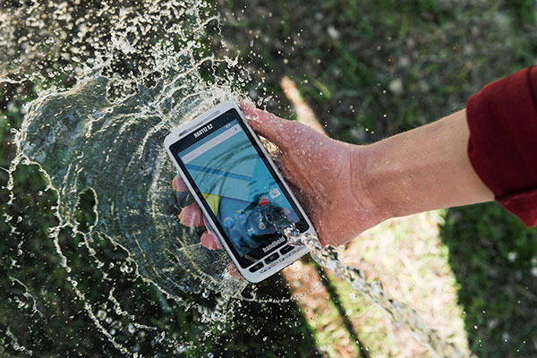
Handheld Group has launched the new Nautiz X2 enterprise handheld, which integrates a high-quality scanner, camera and mobile phone.
The rugged Nautiz X2, available now, can be used in challenging outdoor environments with moisture, dust, extreme temperatures and potential drops, the company says.
The Nautiz X2 features include:
Computing power from a quad-core processor and Android 5.1 Lollipop OS.
High-quality, high-speed scanners with 1D or 2D capability.
An integrated camera with8-megapixel clarity, autofocus and flash.
4G/LTE Android phone functionality.
Google GMS, which gives users access to Google Maps and Play Store apps.
A sunlight-readable, 4.7-inch capacitive display with multi-touch sensitivity.
“The challenge in designing market-leading devices in a given product category is to balance key factors like technology, design, materials and general usability as well as keeping the cost in mind,” says Johan Hed, Handheld Group director of product management. “The brilliance of the Nautiz X2 is that it has that tangible in-the-hand sense of form and fit of a high-end technology device, and we are still able to offer it at an impressive value.”
The Nautiz X2 measures 150 millimeters by 73.5 millimeters, is 16 millimeters deep at the keyboard and weighs 230 grams.
It has an IP65 ingress protection rating against dust, sand and water immersion, the company says. The handleld also meets stringent MIL-STD-810G military test standards for overall durability and resistance to humidity, shock, vibrations, drop, salt and extreme temperatures, and the touchscreen is made of Gorilla Glass for durability.


 Imagine life without GPS. For those of us old enough, that might not be hard to do. For younger people, it’s almost unimaginable. Now imagine that GPS — for whatever reason — is suddenly unavailable. What if you’re not on land, where printed maps are filled with landmarks? What else do you rely on?