Trimble and Exyn Technologies are developing multi-platform robotic autonomy for complex, GPS-denied environments. (Photo: Trimble)
Trimble and Exyn Technologies are working on a proof of concept for a fully autonomous surveying solution for construction.
The solution will integrate the Boston Dynamics Spot robot, the ExynPak powered by ExynAI, and the Trimble X7 total station. It will enable fully autonomous missions inside complex and dynamic construction environments, which can result in consistent and precise reality capture for production and quality-control workflows.
Autonomous robots powered by ExynAI can sense and avoid obstacles, dynamically adapting to the complexity of construction environments. To ensure safety and efficiency, the ExynPak integrates with a robot, supporting Level 4 of autonomous exploration missions without requiring the robot to “learn” about its environment beforehand.
A surveyor can define a 3D volume for a mission, and then the integrated robotic solution handles the complexities of self-navigation without needing a map, GPS or wireless infrastructure.
The integration of the Trimble X7 provides high-speed, high-accuracy 3D laser scanning to capture the state of the environment. The captured data can be uploaded to the Trimble Connect collaboration platform and shared with project stakeholders for further analysis, including a comparison to building information models (BIM) and previous scans to monitor quality and progress. The result is a detailed and accurate map collected with minimal human intervention and risk.
Exyn and Trimble will be demonstrating their technology at the Trimble Dimensions+ Conference Nov. 7-9 in Las Vegas.
Leica Geosystems, part of Hexagon, has launched of Leica iCON gps 160 — a significantly enhanced, next-generation construction smart antenna with features that increase productivity in all stakeout and measurement applications on the jobsite.
The Leica iCON construction portfolio offers a broad range of smart antennas to fit every construction professional’s needs. From basic level to sophisticated high-end applications, Leica Geosystems’ smart antennas are designed and built to withstand challenging site conditions. All of them seamlessly integrate with all Leica iCON construction instruments and controllers as well as the iCON field software for precise, real-time verification.
To expand its portfolio of smart antennas, Leica Geosystems has launched the iCON gps 160, a versatile solution for various applications. It can be used as a base station, as a rover or for machine guidance. The Leica iCON gps 160 is a modernization and enhancement of the successful Leica iCON gps 60, which has been well accepted in the market. The result is a smaller, more compact GNSS antenna with additional features and a larger display for ease of use.
The new Leica iCON gps 160 is particularly suited to complex construction environments with different GNSS requirements — the ability to switch between the different applications is at the users’ fingertips. Besides checking grade, cut and fill, stakeout points and lines, users can also benefit from using this solution for basic-level GNSS machine guidance.
Construction technology must be easy to adopt. Thus, the iCON gps 160 comes with an integrated color display, a user-friendly interface, smart setup wizards and an intuitive construction-specific workflow to help contractors get the most out of their investment from day one.
Size and weight reductions make the iCON gps 160 easy to handle, while the latest GNSS and communication technologies improve data reception, resulting in increased productivity and efficiency.
Photo: Leica Geosystems
The optional tilt feature allows users to measure and stake out points with a tilted pole, which saves time and extends the measurement possibilities on any construction site.
“At Leica Geosystems, we understand that construction surveyors are under pressure and tight schedules to provide accurate, on-demand data that helps deliver projects on time and on budget,” said Matthias Schmidt, manager, Portfolio Field and GNSS, Leica Geosystems. “The iCON gps 160 Smart Antenna sets new standards in construction GNSS antennas. It solves several challenges simultaneously, enabling precise measurement, avoiding mistakes and extra trips on-site, ultimately helping to work toward a more sustainable future.”
Last year I was privileged to be part of a Blue-Ribbon Review Panel for an American Society of Civil Engineers (ASCE) surveying publication. The book is Surveying and Geomatics Engineering: Principles, Technologies, and Applications. I recently received my copy of the published book in the mail and decided to highlight some sections. While preparing this column, the chapters reminded me of how geodesy has expanded into so many different disciplines.
I first mentioned this in my July 2020 article for the “First Fix” column of GPS World, where I stated that the shortage of American trained geodesists poses a significant economic risk for the United States. In that column, I mentioned how geodetic science and technology now underpin many sciences, large areas of engineering (such as driverless vehicles and drones), navigation, precision agriculture, smart cities and location-based services. That is why I believe understanding geodesy is more critical today than ever. In January 2022, Mike Bevis, collaborating with others, prepared a white paper titled “The Geodesy Crisis,” documenting the concern about the lack of trained geodesists in the United States.
Image: Dana Caccamise II
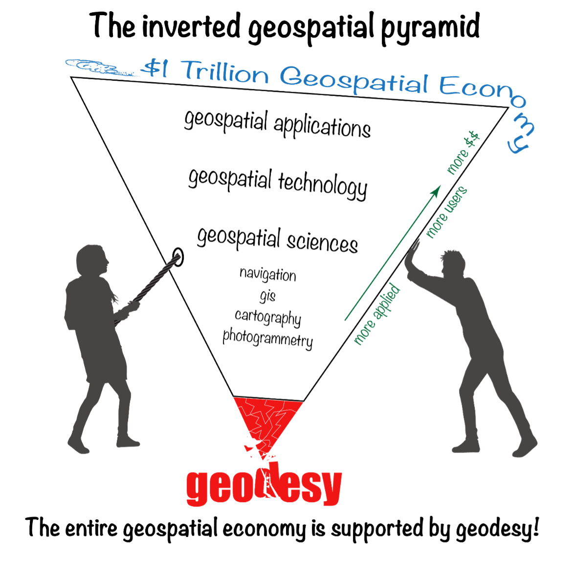
“The inverted geospatial pyramid” graphic depicts how the entire $1 trillion geospatial economy is supported and dependent on geodesy, and how it’s close to collapsing without an increase of support for geodesy. A lack of geodetic expertise in the United States presents a significant challenge, with future impacts on positioning, navigation, mapping and dependent geospatial technologies.
In my opinion, without investment in geodesy, the United States will not have the available skills and knowledge to develop new geodetic technologies and improve models to address challenges to society, such as
how the Earth’s surface is changing as sea level rises and the Earth’s glaciers and ice sheets change on timescales of months
how the tectonic plates are deforming and what physical processes control earthquakes, and
the ability to monitor the temporal changes in Earth’s water reservoirs by measuring changes in Earth’s gravitational field as it responds to the moving water mass and the deformation of the solid Earth caused by moving water.
These challenges need a well-maintained, stable terrestrial reference frame (TRF) with sub-1 mm/year vertical accuracy. Errors in TRF heights can propagate systematically into estimates of atmospheric water vapor, sea level, satellite orbits and other parameters. An accurate TRF can lead to important observations and discoveries because it enables revelations from coherent global motions. (My previous column described the latest International Reference Frame of 2020 [ITRF2020].)
Geodesy has been a significant part of my life for 50 years. I’ve seen a lot, and unless we address the Geodesy Crisis, the innovations in geodetic science of the past will not continue in the future. At least not in the United States.
The Geodesy Crisis paper was mentioned in the Fall 2022 ION Quarterly Newsletter by Everett Hinkley (see the box below). Hinkley noted, “The geospatial community relies on geodesists, though few in the community are fully aware of this connection nor understand the importance of geodesy to their work.” I encourage everyone to download the white paper and the ION Quarterly Newsletter to understand the importance of the need for more trained geodesists.
Excerpt from Everett Hinkley’s Article
“In January 2022, a white paper entitled America’s loss of capacity and international competitiveness in geodesy, the economic and military implications, and some modes of corrective action was released (Bevis et al.). This collaborative paper paints an alarming picture of the dwindling pool of trained geodesists within the United States. The report highlights America’s loss of capacity and international competitiveness in geodesy and states: ‘The U.S. is on the verge of being permanently eclipsed in geodesy and the downstream geospatial technologies. This decline in capability threatens our national security and poses major risks to an economy strongly tied to the geospatial revolution, on Earth and, eventually, in space.’ Though the word crisis correctly describes the dire predicament well, it didn’t occur overnight. Due to several converging trends, the geodesy crisis has been decades in the making. A national lack of geodetic expertise presents a significant challenge with downstream impacts on positioning, navigation, mapping, and dependent geospatial technologies. The Department of Defense, intelligence community, and federal civil agencies’ mapping entities rely on accurate and precise maps for a broad range of purposes, and reliable maps depend on an accurate geodetic underpinning. The geospatial community relies on geodesists, though few in the community are fully aware of this connection nor understand the importance of geodesy to their work.” (Reproduced with permission from ION.)
In my “First Fix” column, I mentioned that I attended The Ohio State University (OSU) to obtain my graduate degree in Geodetic Science in 1979. Therefore, I admitted that I am a little biased — once a geodesist, always a geodesist. That said, in OSU’s geodesy heyday (1960–1990s), many Americans trained were sent there by federal agencies: National Geospatial-Intelligence Agency (NGA), NOAA/National Geodetic Survey (NGS), USGS, Army, Navy and Air Force. During the 1970s, NGS sent two employees back to school every year. These agencies needed geodesists because they were undertaking significant projects, such as the NGS projects to readjust the U.S. national horizontal (NAD83) and vertical geodetic (NAVD88) networks. I was one of the employees NGS sent to OSU to be trained to support the NAD83 and NAVD88.
Today, the environment is different. U.S. federal agencies still need geodesists to develop enhanced and refined geodetic models and tools. However, major U.S. companies, such as Google and FedEx, the automobile industry, the construction industry (automated machine guidance), precision farming companies and mining companies also need more accurate geodetic models, tools and algorithms. Therefore, these companies also need trained geodesists to perform essential research on topics that address their geodetic requirements. As indicated in “the inverted geospatial pyramid” graphic, the entire $1 trillion geospatial economy is supported by geodesy.
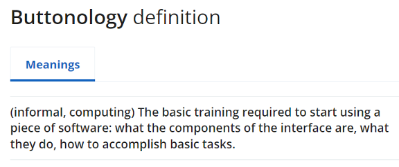
As implied in Hinkley’s article, geodesy has played a role in developing geospatial products but most users didn’t realize that it was their foundation. Since it’s been in the background, everyone assumes it will always be there. A participant at one of my workshops stated that “GPS has made geodesists out of all of us.” In my opinion, the advancements in GNSS equipment and processing software provided some users with a “false sense of knowledge or security” that they understood what was happening within the “black box.” One of my colleagues at NGS said that the new equipment and software programs were creating a field force of “buttonologists.”
These statements concerned me at the time and concern me today. With the last generation of trained geodesists either retired or getting ready to retire, we are at a critical stage of not being able to meet the geospatial needs of the future. As indicated in the white paper, there are significant challenges in rebuilding programs that support the training of geodesists.
Hinkley’s article summarized several action items that could help improve the lack of trained geodesists in the United States. I’ve provided his list in the box below. I’ve highlighted several items the surveying and mapping community can help achieve.
So how do we build and educate the next generation of geodesists?
Make the White House and Congress aware of this crisis, particularly its national security implications; seek direct support in the federal budget to correct this issue. It has become clear that, without engagement at the highest echelons of the U.S. government, averting this current crisis and its eventual outcome is unlikely.
Teach rigorous math in our public schools; follow the scholastic math approach used in many Asian and European countries.
Encourage creative thinking!
Actively market geodesy in high schools as a rewarding career for the math stars before college entry.
Build back, support and sponsor geodesy programs at select universities. This support needs to be strategic, with backing from the highest levels of the U.S. government.
Break our cultural trend of reactions to crises and seize the opportunity to be proactive and prevent the foreseen consequences of this crisis.
Encourage U.S. government support in the form of grants, professional development of staff, and research collaborations/affiliations. There are early efforts underway to bring new talent into the pipeline:
the National Geospatial-Intelligence Agency (NGA) is forming an emerging scientist consortium (ESCON) with partnerships that exist with Ohio State, UT-Austin, and other industry/academic/government partners
a pilot Ph.D. geodesy educational program with three NGA and one NGS employee is in place; the NGA expects to continue growing this program.
the NGA’s new western headquarters in St. Louis will bring 350 companies and organizations into the regional GEOINT ecosystem.
If we answer this call to action collectively, there is hope that a new cadre of U.S. geodesists can be cultivated before it’s too late to recover.
(Reproduced with permission from ION.)
With all that said about the need for more geodesists, one thing that this ASCE publication may do is make some readers realize how much they don’t know about the roots of the technology that they’re using to create geospatial products and services. This knowledge gap is not just correctly using GNSS and other geospatial technology to perform a survey, but also integrating various instruments to create an accurate mapping system, such as mobile mapping and terrestrial laser systems. My intent is not to criticize the expertise or knowledge of anyone, and I only mean to point out that in today’s use of computers and programs, many technical concepts are hidden in “black boxes.” I learned many things about some topics by reviewing this book.
The book is 556 pages and has 15 chapters. As part of my responsibilities as a Blue-Ribbon Panel member, I read every word in the book, and not many people will read the entire book. Still, I would encourage surveyors, engineers, geodesists, photogrammetrists and GIS and remote-sensing practitioners to obtain a copy of the book for reference and to understand the limitations of geospatial technology.
Now to the book’s content. I want to highlight that the forward is written by Juliana Blackwell, director of the National Geodetic Survey (NGS). She states that “A common thread running through the manual is the importance of the National Spatial Reference System (NSRS) to modern geospatial applications.”
Most of my columns highlight something relevant to the NSRS. That’s because the NSRS is the foundation layer for United States federal geospatial products, and geodesy provides the foundation for all geospatial products and services as indicated in the “The inverted geospatial pyramid” figure.
I would also like to highlight a statement by Gene Roe in the preface. He states, “Because entire books could be devoted to each of these topics, this manual only provides a summary, and it points the readers to important references where they can find more details. The manual is meant to provide a comprehensive but general overview to help support education and inform practicing engineers on the important role of the surveying engineer. It is too important for this not to occur.”
I agree with Roe’s statement that the book is important for surveying engineers. Still, I would add that this book is important to anyone working with GNSS and other geospatial data, especially geodesists, surveyors and GIS practitioners.
This publication is edited by three individuals that are licensed surveyors; two of them are geodesists who work for NGS. These individuals have performed a fantastic job of ensuring that all chapters have been reviewed for correctness and that the information provided is current and essential for users of geospatial data.
Readers can download copies of the book and specific chapters here. You can buy it as an e-book or in print. The “Abstract” box summarizes the book from the ASCE Library website.
Abstract
Sponsored by the Surveying Committee of the Surveying and Geomatics Division of the Utility Engineering and Surveying Institute of ASCE and the National Geodetic Survey of the US National Oceanic and Atmospheric Administration
Surveying and Geomatics Engineering: Principles, Technologies, and Applications, MOP 152, is a comprehensive yet general overview to help support education and inform practicing engineers on the important role of the surveying engineer. It provides a much-needed update on the modern practice of surveying and geomatics engineering.
Topics include:
• geodesy
• coordinate systems and transformations
• least squares adjustments and error propagation
• modern surveying and remote sensing technology
• analysis and establishment of control
• geographic and building information systems
• construction surveying, and
• best practices.
MOP 152 can be used as a summary and a reference for practicing engineers, surveying and otherwise, to help provide a solid understanding of the state of the surveying and geomatics engineering field.
Below is a list of the chapters and their authors. This column cannot highlight everything important in this book, but I will select a few items to which I believe users of geospatial data should pay attention.
Chapter Titles
Chapter Number
Chapter Title
Author(s)
Forward
Juliana P. Blackwell
Preface
Gene V. Roe
Acknowledgments
Daniel T. Gillins
1
Engineering Surveying Within ASCE
Gene V. Roe
2
Geodesy and Geodetic Computations
Earl F. Burkholder
3
Map Projections and Local Coordinates Systems
Michael L. Dennis
4
Local, Regional, and Global Coordinates Transformations
Michael L. Dennis
5
Analysis and Adjustment of Observational Errors
Charles D. Ghilani
6
Satellite-Based Surveying Technology
Jan Van Sickle
7
Leveling and Total Stations
N.W.J. Hazelton
8
Terrestrial Laser Scanning
Michael J. Olsen
9
Mobile Terrestrial Laser Scanning and Mapping
Michael j. Olsen, Jaehoon Jung, Erzhuo Che, Chris Parrish
10
Aerial Surveying Technology
Michael J. Starek, Benjamin E. Wilkinson
11
Survey Control
Daniel T. Gillins
12
Construction Surveys
Marlee A. Walton
13
Survey Records
Andrew C. Kellie
14
Information Systems in Civil Engineering
Yelda Turkan, Dimitrios Bolkas, Jaehoon Jung, Matthew S. O’banion, Michael Bunn
15
Professional Services and Design Professionals Agreements
David E. Woolley, Lisa D. Herzog
As a geodesist, I usually focus on topics relevant to geodetic science. This book has a lot of topics that use geodesy concepts to create an engineering product or service. For example, chapter 2, “Geodesy and Geodetic Computation” by Earl Burkholder, provides a good summary of geodetic concepts that anyone using or generating geospatial products should know and understand. It gives basic equations without lengthy derivations of how they were developed.
In my opinion, chapter 3, “Map Projections and Local Coordinates Systems” by Michael Dennis, does the best job of explaining the concepts of map projections that are relevant to the surveying and mapping community. Many GIS practitioners use map projections in their software but don’t have a working knowledge of what’s happening to their original data. This chapter describes the current United States State Plane Coordinate System of 1983 (SPCS83) and the future State Plane Coordinate System of 2022 (SPCS2022) that is scheduled to be adopted in 2025. Dennis uses figures and diagrams to describe map projections, angular and linear distortion, and methods for reducing map projection distortion to make it easier for readers to understand the concepts. One section of interest to many surveyors after SPCS2022 is adopted is the Low-Distortion Projection (LDP) Coordinate Systems section. This is useful because, in SPCS2022, many states have designed LDP systems for their state’s SPCS2022. The box below provides a diagram with the number of zones for each state.
Image: NGS Presentations Webpage “Grids for the Future: A New Approach for Designing State Plane Coordinate System Zones” by Michael Dennis.
One purpose of an LDP is to reduce linear distortion; it is not a new concept. Many surveyors have performed a simplified form of it for decades. It’s known by many as a “modified” or “scaled” State Plane. The American Congress on Surveying and Mapping (ACSM) taught a workshop for decades describing how to compute a “modified” State Plane Coordinate. I was an instructor of this class in the 1980s and 1990s. “Modified” State Plane Coordinates had several issues, but they worked reasonably well in small areal extents. Today, with the advancements in computers and computer software, there are better ways to accomplish an LDP. Dennis’ section does a great job explaining the new SPCS2022 and the design of LDPs in the SPCS2022. The use-case examples provide a simplified description of understanding the linear distortion behavior in an area.
Chapter 4, “Local, Regional, and Global Coordinate Transformation” by Michael Dennis, is one that every surveyor and GIS practitioner should read. Dennis highlighted the differences between “equation-based” transformations and “grid-based” transformations, as well as combined equation-based transformations with grid-based transformations. Understanding the information provided in chapter 4 will be important when NGS replaces the NAD 83 (2011) and NAVD 88 datums with the new, modernized NSRS in 2025. NGS will provide models and tools for users to perform coordinate transformations, but hopefully, some users will want to understand what’s happening behind the scenes.
Chapters 8 and 9 discuss laser scanning systems. In chapter 8, “Terrestrial Laser Scanning,” the “Data Quality Considerations” section highlights common artifacts or limitations encountered with terrestrial lidar system data. The authors provide many examples of these artifacts, making the concept easy to understand. At the end of this chapter, there are 14 pages of references that will be very helpful to users involved with terrestrial laser scanning systems.
Chapter 9, “Mobile Terrestrial Laser Scanning and Mapping,” is very informative, especially the section on georeferencing. This section is not just the description of properly using GNSS to perform a survey, but also the integration of various instruments to create an accurate mobile mapping system. I like how the authors discussed the error sources in georeferencing the system, listed the source, and provided an explanation of the error.
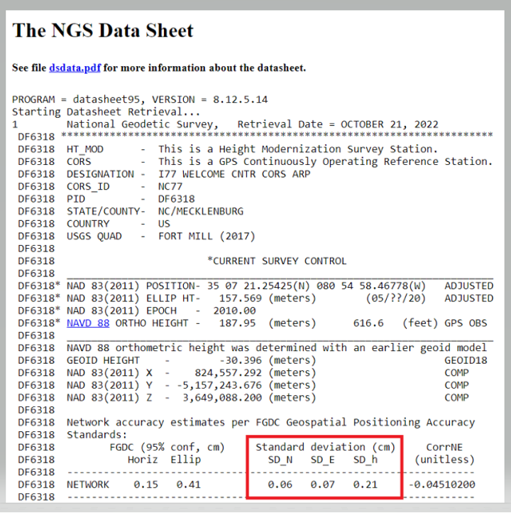
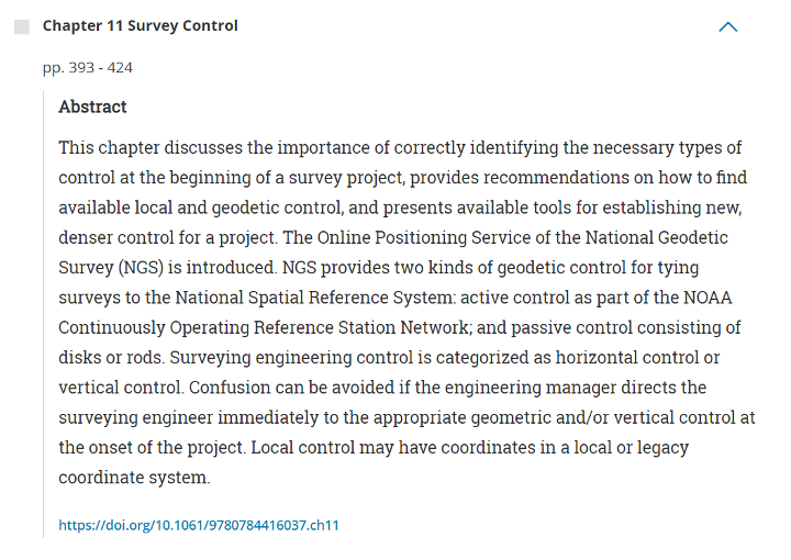
Anyone performing a GNSS survey project that meets NGS’s requirements needs to read chapter 11. I like the section describing how users should evaluate CORSs before using them as control. Evaluating CORS is something all users should do before using any CORS in their project, because not all CORS are created equal. See the excerpt from chapter 11 below for the recommended steps from the author.
Excerpt from Chapter 11 – Steps for Evaluation of CORS
The author recommends the following steps:
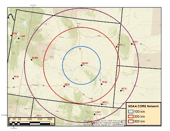
1. Choose stations that are within 100-300 km of a project site. It is well known that errors in GNSS baseline processing are directly correlated with baseline length (Chapter 6). Tropospheric delay is reduced when baselines are shorter and atmospheric conditions at each end of the line are similar. In addition, mutual satellite visibility at each end of the line for differencing diminishes as baselines grow longer. That said, errors in GNSS processing are more occupation time-dependent than baseline length-dependent (Eckl et al. 2001). Therefore, for short GNSS sessions (i.e., < 2 hours), choose CORS within approximately 100 km as control; for moderate GNSS sessions (i.e., 2 to 8 h), choose CORS within approximately 300 km. Note that even longer baselines can be successfully processed when GNSS sessions are very long in duration (e.g., up to 2,000 km for 24 h sessions).
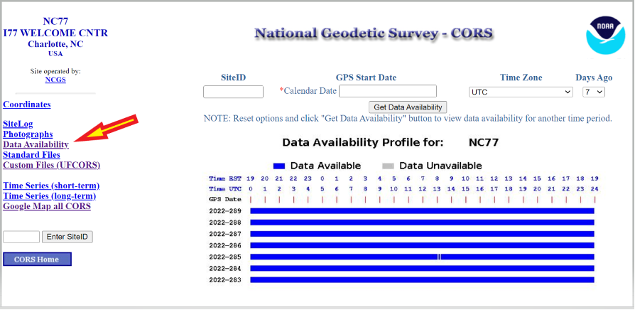
2. Determine if GNSS data are available at a given CORS during the time of your survey. Of course, if data are unavailable, then the station simply cannot be used as control. NGS provides a tool known as “User Friendly CORS (UFCORS)” for entering a date and time range to view available data at a given station (NGS 2021c). This tool can also be used to download the raw GNSS data for processing and adding a station to the survey network.
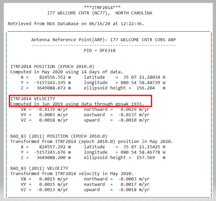
3. As discussed previously and when possible, choose a CORS with computed velocities rather than modeled velocities from HTDP. NGS provides tables of official coordinates with “computed” versus “htdp” coordinates and velocities on the website for CORS.
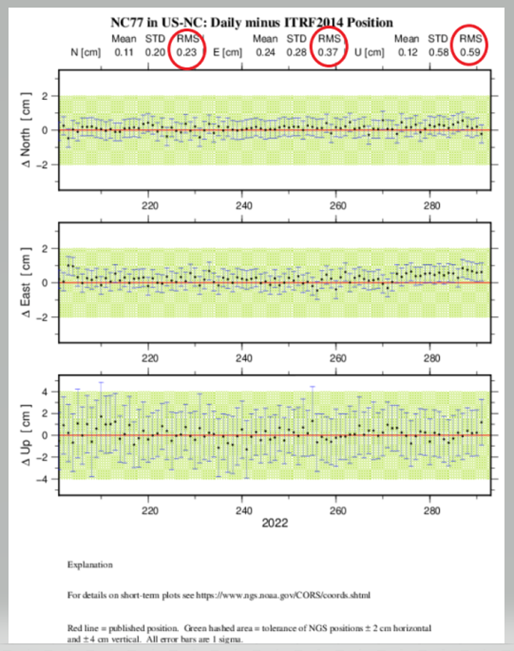
4. Review the aforementioned short-term time-series plot for the station, ideally at the time of the project. Stations with large spikes, data gaps, bias from the published “red” line, or large standard deviations should be avoided. A good rule-of-thumb is for the RMS in the short-term time-series plot (Figure 11-2) to be less than 1.0 cm in north and east and 2.0 cm in the up direction in a local geodetic horizon frame at the station.
5. Examine the formal uncertainties for the official coordinates of the CORS. Standard deviations in north, east, and up are provided on the station’s datasheet, accessible from the webpage for the CORS (more on datasheets are discussed in the following under Passive Control). Stations with unusually large standard deviations (> 3 cm) should be avoided. Note that standard deviations are not available for CORSs with modeled velocities.
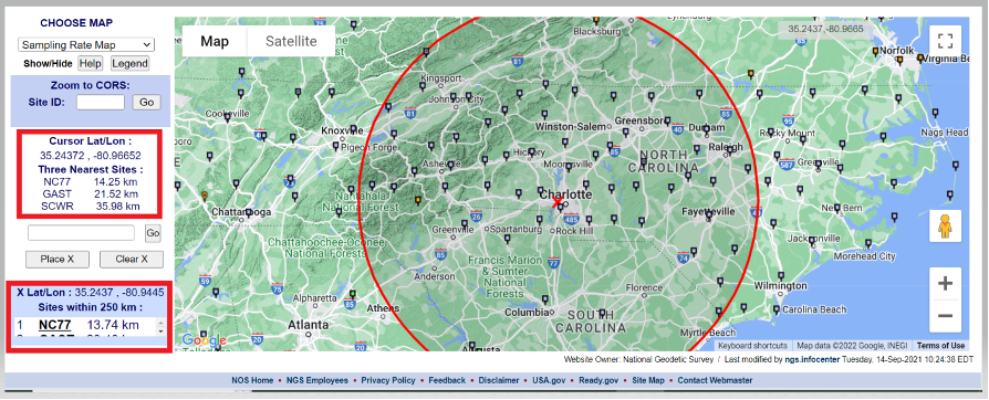
I believe that the evaluation of NOAA CORS is critical, so I’ve described Dan Gillins’ “Steps for Evaluation of CORS” below. First, users can access the NOAA CORS using the NGS CORS Map utility. After the map appears, users can move the cursor over the center of the project area, where it provides the location of the cursor and the three closest CORS. Users can click on a CORS icon and get coordinates and other information about the CORS. Also, they can place an X on the map, and the utility will draw a 250-km circle around the point. The box in the lower left-hand side of the map provides a list of the sites within 250 km of the marked location.
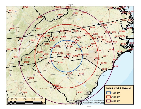
Users can download the NOAA CORS coordinates and velocities (computed and modeled). I downloaded the files and plotted three circles (with radii of 100, 200, and 300 km) around CORS NC77 in Charlotte, North Carolina. I only plotted CORS that are operational and have computed velocities. North Carolina has a lot of CORS to select from. In contrast, I’ve plotted three circles (also with radii of 100, 200 and 300 km) around CORS WYRF in Casper, Wyoming.
Buffer Zones around Charlotte, NC
Image: Dave Zilkoski
The plot depicting the buffer zones around Casper indicates that there are no CORS within the 100-km circle and only a few between 100 and 200 km.
Buffer Zones around Casper
Image: Dave Zilkoski
The data availability of the CORS site can be obtained by clicking on the CORS icon, selecting “Get Site Information,” and then selecting “Data Availability.”
There are too many chapters to describe each one, but I encourage users to check each chapter’s abstract on the ASCE website and decide which ones would be the most beneficial to them (see the box titled “Abstract for Chapter 11 Survey Control”). The manual provides numerous references and can serve as a helpful resource for finding further details on the fields of geodesy and surveying.
A goal of mine is for some readers of this column to obtain enough knowledge to “whet their appetite” and encourage them to pursue an education in geodesy and surveying. Others who are influential in federal government programs and those responsible for geospatial research for industries will recognize the need for more trained geodesists in the United States and help by doing the following:
actively market geodesy in high schools as a rewarding career for the math stars before college entry
build back, support, and sponsor geodesy programs at select universities; this support needs to be strategic with backing from the highest levels of the U.S. government
encourage U.S. government support in the form of grants, professional development of staff, and research collaborations/affiliations.
Leica Geosystems, a part of Hexagon, received the prestigious Wichmann Innovations Award at this year’s Intergeo in Essen, Germany, for its Leica AP20 AutoPole.
The Wichmann Innovations Award honors new technology that stands out for innovation, user-friendliness and practicality. A panel of industry leaders shortlisted the submissions. Subsequently, the public was able to weigh in by casting a vote for their favorite finalist.
The Leica AP20 AutoPole is an innovative solution for automated total stations that features tilt compensation, automatic pole height readings and unique target identification. The technological convergence in the AP20 addresses core pain points in today’s total station workflows by making it possible to measure with a tilted pole, adjust height readings in the software automatically and prevent the station from locking onto unwanted targets.
Photo: Leica Geosystems
“The Leica AP20 AutoPole boosts efficiency by removing the last analog steps in robotic total station workflows. We were pleased when customers told us they were able to double their productivity on some projects,” says Hans-Martin Zogg, business director TPS at Leica Geosystems, part of Hexagon. “This award represents the acknowledgment of the expert jury as well as the broader surveying community, and winning it is a wonderful recognition of our team’s accomplishment.”
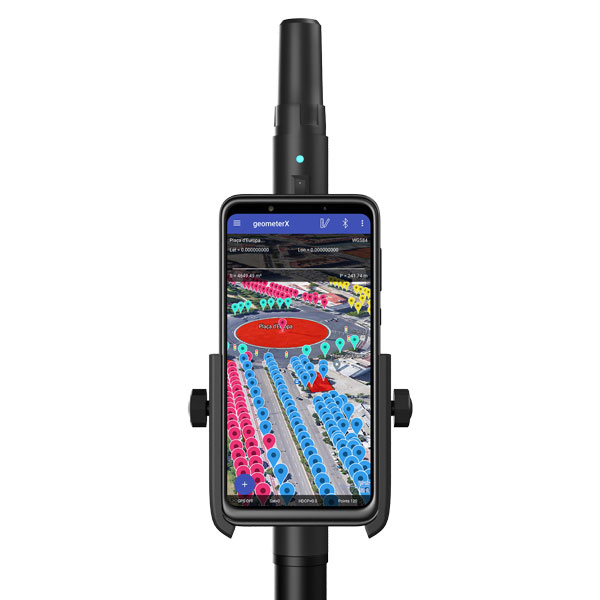
Geometer International, a Ukrainian developer of GNSS/RTK instruments and applications for satellite positioning, has introduced the Walker RTK, a dual-frequency L1, L2 RTK receiver in the compact form factor of a portable RTK device.
The Walker RTK is a lightweight, small-sized, affordable and full-featured device for collecting, storing and processing geo-referenced data on the survey site. According to the developer, a GNSS receiver in a convenient and affordable format will significantly expand the use of RTK technology. The new technology will be suited to most tasks requiring centimeter precision positioning and measurements in a 3D coordinate system.
Compact and lightweight, Walker RTK is the ideal solution for field workers working away from the office. The new device can be operated with just one hand, significantly improving the productivity of service personnel.
Possible applications for GNSS Walker RTK include surveying, utilities, solar power plant engineering, trenching and pipeline installation, drilling, forestry and municipal infrastructure control.
What’s under the bonnet of Walker RTK?
The Walker RTK is built around a 2-frequency L1/L2 184 channel board and a sensitive Helix antenna, satisfying up to 90% of basic user requirements. The tube-shaped housing geometry allows it to fit with any universal mount. The receiver weight is only 0.25g (0.470 with smartphone holder) due to the aluminum alloy housing with a protective coating. The Walker RTK has a built-in Li-Ion battery with enough power for 24 hours of continuous operation without additional recharging. The new energy-efficient architecture of the unit achieves this.
The GNSS receiver has the minimum amount of leading interfaces, resulting in high IP67 dust and waterproof rating. The device can be paired with a smartphone or tablet via Bluetooth, while connection via Bluetooth low energy is also planned for a future release.
Compatible with satellite systems
Walker RTK can track and determine geo-position using signals from all known existing satellite systems. This feature makes it possible to achieve the centimeter-level accuracy of an RTK solution within seconds.
GNSS signals processed by the Walker RTK GNSS receiver:
Thanks to NMEA messaging, the Walker RTK GNSS receiver is fully compatible with any professional or freeware geolocation software, providing high accuracy and reliable RTK-corrected positioning.
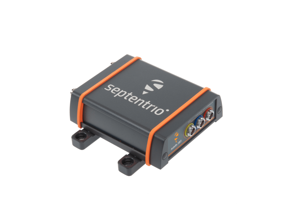
Septentrio, a leader in high-precision GNSS positioning solutions, introduced the AsteRx SB3 ProBase, the latest generation of GPS/GNSS base station receivers, designed for the creation of top-quality measurements for RTK and differential corrections.
The AsteRx SB3 ProBase is an IP68-housed GNSS base station receiver, featuring the latest quad-constellation GNSS technology for the best quality measurements. The new ruggedized receiver complements the SB3 receiver family: the AsteRx SB3 Pro, rover receiver, the AsteRx SB3 Pro+ rover and base receiver and the AsteRx SB3 CLAS, dedicated to the Japanese market.
“Customers often look for a simple, high-quality and easy-to-integrate base station to set up local high precision RTK or to densify their network and the AsteRx SB3 ProBase is the perfect solution,” said Silviu Taujan, Product Manager at Septentrio. “Thanks to its configuration flexibility and monitoring capabilities it is extremely easy to deploy and configure the SB3 ProBase. Plus, it comes with our industry-leading GNSS+ technologies, including anti-jam and anti-spoofing technology (AIM+) for unbeatable robustness and reliability.”
AsteRx SB3 products are pin-to-pin compatible with Septentrio’s popular AsteRx SB ProDirect receiver and with the recently released AsteRx SBi3 GNSS/INS system, making it simple to change receivers.
Trimble has announced Project MEP, a construction management solution that provides visibility into mechanical, electrical and plumbing (MEP) workflows including estimating, change management, project management, detailing and fabrication. Project MEP allows for greater efficiency, collaboration and visibility across projects in the electrical, mechanical, HVAC and plumbing contractors fields.
Project MEP manages drawings, documents, budgets and field productivity while extending construction management workflows with a suite of capabilities including estimating, submittal management and fabrication collaboration. The solution also provides project managers with the tools to identify issues faster, reduce rework and deliver more profitable projects. Project MEP is available as part of Trimble’s cloud-based construction management platform, Trimble Construction One.
“MEP project managers are closely involved with every detail of a project from bid to closeout, but in today’s construction environment the data they need isn’t always readily available,” said Lawrence Smith, vice president of Trimble Construction Management Solutions. “With Project MEP, Trimble is breaking down information silos … while also providing the tools project managers need to run a job more efficiently. Now MEP contractors have a construction management solution that gives them the big picture of project health and the ability to track details such as the status of a spool.”
Project MEP addresses MEP workflows including bid turnover, model collaboration, submittal management, design to fabrication, model-based estimating and field-to-office.
A roundup of recent products in the GNSS and inertial positioning industry from the October 2022 issue of GPS World magazine.
OEM
Software
Aids GNSS/INS installation
Photo: Septentrio
The RxLeverArm software tool aids integration of GNSS receivers that include inertial navigation systems (GNSS/INS). RxLeverArm is part of Septentrio’s RxTools software package included with every Septentrio GNSS/INS receiver. The new tool visualizes, validates and automatically calibrates the exact distance between the INS sensor and the antenna, removing the need for accurate distance measurements with complex instruments. For lever-arm compensation, users only need to measure the rough distance between the INS sensor and the main GNSS antenna reference points on the vehicle. Data is then logged under open-sky conditions, which allows the RxLeverArm tool to optimize the initial rough distance measurement and prevent common errors such as sign inversion.
Enables proof of concept for IoT products and applications
Photo: u-blox
The u-blox XPLR-IOT-1 IoT explorer kit is an all-in-one package to test, evaluate and validate applications for the internet of things (IoT). The board hosts an ultra-low-power MAX-M10S positioning module capable of concurrently tracking four GNSS constellations, delivering highly reliable location data. Integrating relevant u-blox technologies and services into a capable prototyping platform with a vast selection of sensors and interfaces as well as cloud connectivity, XPLR-IOT-1 makes it easier to explore the potential of IoT applications.
The LC29H is a dual-band multi-constellation GNSS module built using the Airoha AG3335 platform. It is available in multiple variants and optionally integrates real-time kinematic (RTK) and dead reckoning. The LC29H series offers high performance with power efficiency to meet the market needs of high-precision positioning at the centimeter and decimeter levels. The LC29H concurrently receives and processes signals from GPS, GLONASS, BeiDou, Galileo and QZSS. The modules are suited to an expanding market for autonomous lawn mowers, drones, precision agriculture, micro-mobility scooters and delivery robots.
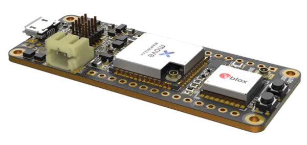
The Cicerone LoRa/GNSS board is a high-performance, low-power, Arduino MKR-compatible development board based on the u-blox MAX-M10S GNSS module and the MAMWLE LoRa module. It delivers high-performance GNSS, long-range wireless connection, and high-performance processing in a low-power solution for optimal battery life. The board allows users to build tracking applications worldwide with meter-level accuracy and to communicate long-range, low-power data via LoRaWAN. The integrated Li-Po charging circuit enables the Cicerone board to manage battery charging through the USB port. It has a compact 63 mm x 25 mm form factor and is compatible with all Arduino MKR shield boards. These boards all share a common pinout to enable developers to easily add expansions with minimal software changes.
The Snapdragon W5 Gen 1 and W5+ Gen 1 platforms are designed to advance ultra-low power and breakthrough performance for next-generation connected wearables with a focus on extended battery life and premium user experiences. They incorporate innovations including low power islands for GNSS, Wi-Fi and audio; ultra-low power Bluetooth 5.3 architecture; and low power states such as Deep Sleep and Hibernate. New enhancements to the flagship Snapdragon W5+ platform offer 50% lower power, 2x higher performance, 2x richer features, and 30% smaller size, compared to the previous generation. The purpose-built platform is comprised of a 4 nm-based system-on-chip and 22 nm-based highly integrated always-on co-processor. By using these platforms, manufacturers can scale, differentiate and develop products faster in the continuously growing and segmenting wearables industry, Qualcomm said. Qualcomm also announced two reference designs from Compal and Pegatron, which showcase the capabilities of the platform and the company’s collaboration with ecosystem partners, helping customers develop products faster.
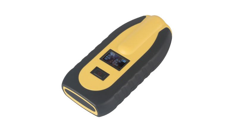
The pocket-sized vRTK GNSS real-time-kinematic (RTK) receiver is equipped with dual cameras to enable non-contact image surveying. It also has a nine-axis IMU module with auto installation for tilt surveying. Visual positioning technology combines imagery with high-precision positioning equipment, allowing users to obtain the location of the target from a distance. The Live View Stakeout function improves stakeout speed, while non-contact measurement greatly improves the usable range of GNSS. The vRTK receives 1,408 channels (GPS, GLONASS, BeiDou, Galileo, QZSS, IRNSS and SBAS). A new generation of GNSS engine supports the new frequency points B1C, B2a and B2b RTK decoding of BeiDou-3 satellites.
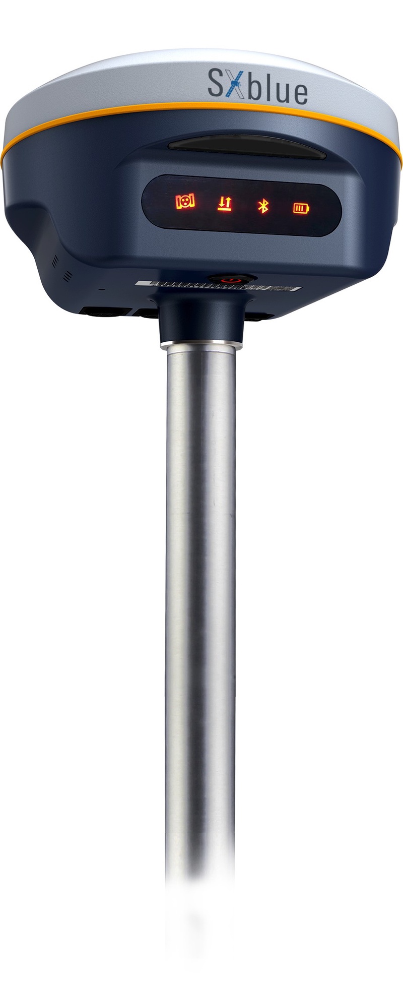
The SXblue SMART features an engine capable of tracking all-in-view GNSS signals, with interference mitigation and optimization for handling a wide frequency band. Weighing 850 g including battery, the SXblue SMART is compact and rugged. Its radio link is based on the Farlink protocol that allows a range of up to 8 km while reserving a wide bandwidth for transmission of real-time kinematic (RTK) data. In addition to a tilt sensor for measurements in hard-to-reach places, the SXblue SMART features a high-performance attitude measurement module that can detect and measure movement of the device. Also integrated are an inertial measurement unit and a thermometer for monitoring and controlling its internal temperature.
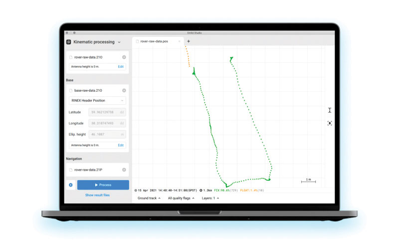
Emlid Studio is a new post-processed kinematic (PPK) application designed specifically for post-processing GNSS data. It allows users to convert raw GNSS logs into RINEX, post-process static and kinematic data, geotag images from drones (including DJI brand), and extract points from survey projects completed with Emlid’s ReachView 3 app. With Emlid Studio, users can post-process data recorded with Emlid Reach receivers and other GNSS receivers or NTRIP services. Post-processing requires RINEX observation and navigation files. Raw data in UBX and RTCM3 format also can be used through conversion.
The P1 GNSS receiver has a high-precision module that tracks GPS, GLONASS, BDS, Galileo, QZSS and SBAS to deliver centimeter-level real-time kinematic (RTK) accuracy even in harsh environments. It is also equipped with an anti-jamming and anti-spoofing algorithm. The P1 GNSS receiver has integrated the GNSS module and GNSS antenna while keeping the device as small as a smartphone, which makes it portable enough to be worn around the neck or placed in a pocket. With 4G/Bluetooth communication, the P1 supports real-time positioning data transmission, providing users with a stable correction data steam and positioning data uploads. The P1 also can be mounted on a pole.
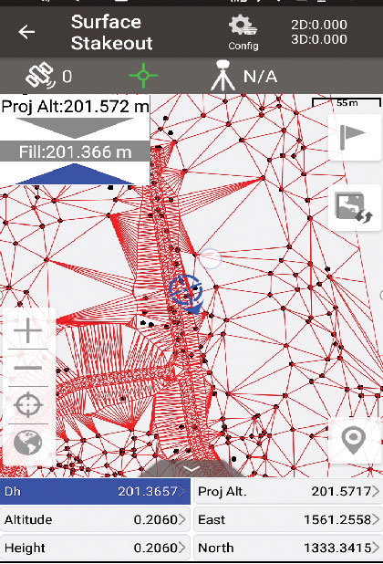
Nuwa surveying smartphone app version 2.3.3.2 has vector map import and digital surface stakeout. The Nuwa app runs on Android and is reliable and easy to operate. It has rich and powerful functions that can help surveyors complete measurements more efficiently and accurately. The app is designed to work with the David and Oscar GNSS receivers from Tersus GNSS, plus other receivers that support NMEA-0183. Features include the ability to configure base, rover and static surveys; graphical interface with background map (online/import); CAD stakeout, road stakeout and earthwork; data management (import/export multiple formats); and Bluetooth and USB connection support.
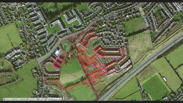
Version 3.2 of the survey application 1Edit allows the use of Web Maps (WMS) to be used as background layers, making it easier for surveyors to identify assets and changes in context. It provides easier configuration of background maps and supports hybrid working practices for surveyors. Where offline background maps are required, 1Edit supports multiple raster files and handles large image files, providing visual context for geospatial data when there is no data signal. Enhanced support for complex geometries increases efficiency as features with multiple parts share common attributes and IDs.
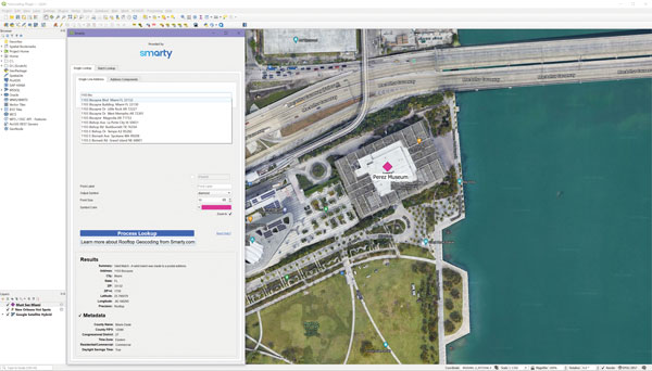
The Smarty U.S. Geocoding QGIS Plugin provides an easy way for users of the software platform to validate, standardize, and convert addresses to their latitude and longitude coordinates (geocodes). The plugin allows manual address entry as well as batch geocoding via CSV. It features a 95% match rate with the actual rooftop and parcel, as well as providing sub-address geocoding that can match secondary addresses such as apartment units and office-suite rooftops in building. The free plugin also includes supplemental metadata useful for many geographic information system (GIS) purposes.
Datasets for the United States, UK, Canada, Australia and Europe
Photo: Maptitude
Maptitude 2022 is a major release of the geographic information system (GIS) and mapping software. It includes up-to-date, accurate data encompassing expenditure, geodemographic segments, gross domestic product, medical and banking locations, branded business locations, traffic counts, building footprints, address points and financial assets, as well as the tools to leverage this information to improve the location intelligence of organizations in markets such as healthcare, franchising, communications, logistics, retail, real estate and banking.
The Mesa Pro rugged tablet features 11th-generation Intel Core processors, a Windows 11 operating system, device customization options, a large sunlight-readable display and the “Juniper Rugged” company design. Standard Mesa Pro units come with an 11th Gen Intel Core i5 processor and 16 GB of LPDDR4x RAM. Core i7 and Celeron versions are also available. Each Mesa Pro configuration offers powerful performance and allows users to select the computing performance that fits their needs and budgets.
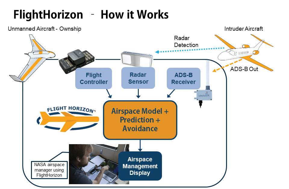
Data fusion across multiple data sources, including ADS-B
Photo: Vigilant Aerospace
FlightHorizon COMMANDER is a situational awareness and safety system for UAV airspace management. The system provides airspace managers with either a 2D or 3D view of all aircraft in the selected airspace using a combination of sensors and data sources to create an airspace safety picture for pilots, airspace managers and command centers. The system is based on an exclusively licensed NASA patent and prototype that has been used in extensive flight testing. FlightHorizon COMMANDER functions as a visualization tool for airspace management, an active situational awareness tool, and a detect-and-avoid system that enables unmanned aircraft to avoid other aircraft and keeps drone pilots and airspace managers aware of the location and air traffic around their UAS and in their airspace.
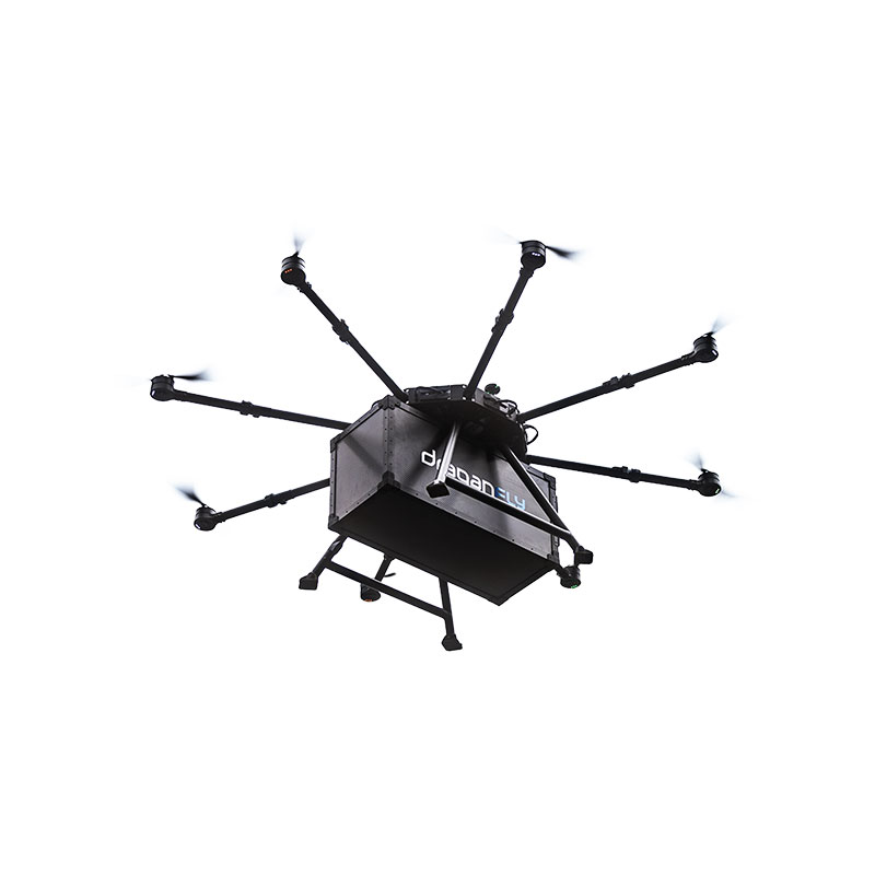
The Draganfly Heavy Lift Drone is a versatile, multi-rotor unmanned aerial vehicle designed to enhance deliveries and flight times. Compatible with a variety of interchangeable payloads, the heavy-duty drone can carry more and fly longer than the typical professional drone. It has a payload/cargo-lift capacity of 30 kg (67 lbs) and up to 55 minutes of flight time. The industrial UAV handles heavy winds and high elevations with ease. Its lifting capacity permits flexibility in carrying large high-end sensors such as hyperspectral and bathymetric lidar to conduct large-area surveys.
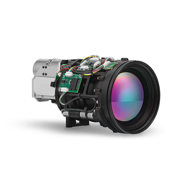
Allows rapid MWIR integration for commercial, industrial and defense applications
Photo: Teledyne FLIR
Part of the Neutrino IS series, the Neutrino LC CZ 15-300 is a new mid-wavelength infrared (MWIR) camera module with integrated continuous zoom lenses. Designed for integrated solutions requiring crisp, long-range MWIR imaging, the camera offers size, weight, power and cost (SWaP+C) benefits to original equipment manufacturers (OEMs) and system integrators for airborne, unmanned, C-UAS, security and targeting applications. The LC CZ 15-300 offers high performance, 640 x 512 high-definition MWIR imagery and 15 mm to 300 mm zoom capability for ruggedized products requiring long life, low power consumption and quiet, low-vibration operation. The camera module and lens are designed for each other, providing optimal performance.
A miniature drone with flapping wings was demonstrated at the Teknofest Black Sea aviation and defense industry event, which took place Aug. 30 to Sept. 4 at the Samsun Çarşamba Airport. With its low detectability, the nano drone is being developed to perform reconnaissance and surveillance missions. It is still in research and development.
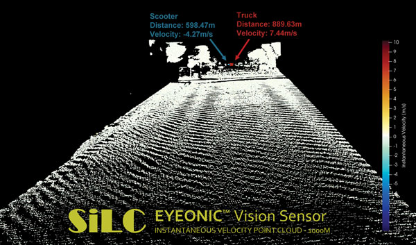
The Eyeonic Vision Sensor can perceive, identify and avoid objects at a range of more than 1 kilometer. The sensor is a frequency modulated continuous wave (FMCW) lidar transceiver that uses a silicon photonic chip. Long-range visibility is a requirement for autonomous vehicles, which require sufficient awareness to evade obstacles at highway speeds. This capability requires vision sensors to provide millimeter-level accuracy and depth at instantaneous velocity. The highly detailed and ultra-long-range information from the Eyeonic Vision Sensor enables robots to classify and predict their environments. The sensor is designed to be integrated into autonomous vehicles, security solutions and industrial robots.
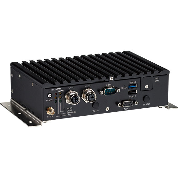
The nROK 1030 is a compact, rugged entry-level vehicle computer with an advanced GNSS receiver. The u-blox NEO-M9N module supports GPS, GLONASS, Galileo, BeiDou and QZSS signals. An Intel Atom x6211E dual-core processor 1.3 GHz/3 GHz (burst) is designed for harsh in-train environments. Its fanless, compact design is suitable for vehicles with limited space. The nROK 1030 has onboard CAN 2.0B for vehicle diagnostics and driver behavior management. WLAN Wi-Fi 6/6E/Wi-Fi 5 and WWAN 5G NR/LTE wireless data connectivity is optional. The nROK 1030 is flexible to meet the demands of various rolling-stock applications, such as wireless gateway, infotainment and digital radio data/voice transmission systems.
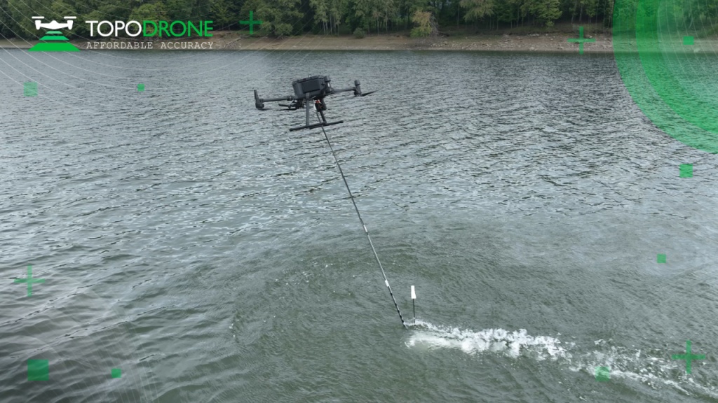
TOPODRONE, a Swiss-based designer and manufacturer of high-precision lidar equipment for installation on drones, vehicles and backpacks, launched AQUAMAPPER, a UAV-based solution for bathymetric surveying and marine construction.
AQUAMAPPER contributes to a complete set of photogrammetry, lidar and bathymetry surveying solutions from TOPODRONE. The product, compatible with the DJI Matrice 300 RTK, provides a combination of high-speed efficiency (up to 14 km/h) and accuracy mounted on a UAV. The application areas include an open sea bathymetric survey up to 100m depth, quantity survey and calculation of sediments and periodic maintenance survey of storage pools.
Photo: TOPODRONE
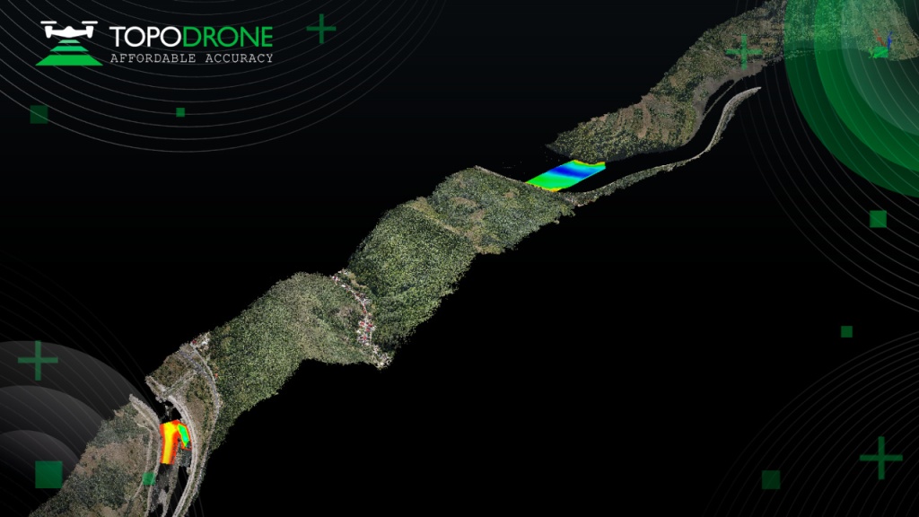
The new data-collecting device has been successfully used alongside TOPODRONE’s LiDAR ULTRA equipment for airborne surveying at a highway construction project in one of the toughest terrains in Romania, EU, including 7 tunnels, 24 bridges and 18 viaducts. The project was performed by the Romanian company GRAPHEIN TOPO SA to deliver a full digital twin of a studied area.
Photo: TOPODRONE
The TOPODRONE LiDAR ULTRA on board a DJI M300 drone was used to capture laser scanning data from an altitude of 100 m to 120 m over rugged terrain forest area to cover a corridor 32 km long and 400 meters wide in 14 flights while AQUAMAPPER connected to the same DJI M300 drone performed a bathymetric survey over six river crossings.
“The key advantage of the new bathymetric equipment from TOPODRONE is the ability to capture a riverbed with centimeter-level accuracy with high speed in fully automatic mode and without using any boat,” said Andrei Sueran of GRAPHIEN TOPO SA. “The combination of an echosounder, GNSS and inertial measurement system helps to get accurate results after data post-processing.”
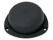
Tallysman Wireless has added the housed SSL990XF full-band survey-grade GNSS antenna to its line of GNSS products.
The SSL990XF uses a derivative of Tallysman’s patented VeroStar antenna element to provide full GNSS + L-band corrections frequency coverage.
The SSL990XF is 63 mm in diameter and 28 mm tall and weighs ~50 grams, making it a very small and light housed full-band precision antenna. It has a very tight average phase-center variation of 4 mm or lower for all frequencies and overall azimuths and elevation angles.
The full-band SSL990XF antenna supports GPS/QZSS L1/L2/L5, QZSS L6, GLONASS G1/G2/G3, Galileo E1/E5ab/E6 and BeiDou B1/B2ab/B3, as well as L-band correction services. Also supported in the region of operation are satellite-based augmentation systems: WAAS (North America), EGNOS (Europe), MSAS (Japan), or GAGAN (India).
The SSL990XF is housed in a weatherproof (IP67) enclosure and is mounted using either adhesive tape or a mounting collar that includes a waterproofing O-ring. Two antenna cable connector options are available. The first is a female SMA, and the second is an MCX. It is an ideal antenna for precision UAV and all applications where light weight and precision matter.
The radio-frequency spectrum has become congested worldwide as many new LTE bands have been activated, and their signals or harmonic frequencies can affect GNSS antennas and receivers.
In North America, the planned Ligado service, which will broadcast in the frequency range of 1526 to 1536 MHz, can affect GNSS signals. Similarly, new LTE signals in Europe [Band 32 (1452–1496 MHz)] and Japan [Bands 11 and 21 (1476–1511 MHz)] have also affected GNSS signals. Tallyman’s new SSL990XF with eXtended Filtering (XF) technology mitigates the interference effects of these new signals.
Hexagon AB, which offers digital-reality solutions combining sensor, software and autonomous technologies, will integrate AVVIR’s artificial-intelligence-powered technology stack into its portfolio of solutions that address challenges of the construction lifecycle.
Since 2017, AVVIR has enabled intelligent, data-driven job sites that empower commercial, infrastructure and industrial construction professionals to reliably and safely deliver on schedule and within budget, Hexagon stated in a press release.
AVVIR’s reality-analysis platform is focused on building information modeling (BIM). It is designed to improve project workflows, schedules and outcomes by leveraging onsite reality-capture data, enriched BIM models and artificial intelligence. The solution gives construction teams control with automated schedule tracking, cost and earned value analysis, installation issue detection, and an updated BIM with as-built conditions.
On Aug. 5, the National Geodetic Survey (NGS) stated it will be updating the NOAA CORS to be aligned with the latest International Terrestrial Reference frame, ITRF2020 (see below). As stated in the announcement, NGS will soon compute a third multi-year continuously operating reference station (CORS) solution, MYCS3.
The last multi-year CORS solution, MYCS2, was performed by NGS in 2019. I discussed the MYCS2 in my February 2019 and April 2019 columns. This new multi-year CORS solution will be important to the 2022 modernized National Spatial Reference System (NSRS), because NGS will establish a strict mathematical relationship between the 2022 NSRS frames and the ITRF2020 frame. This will allow direct access to the NSRS (NOAA Technical Report NOS NGS 67).
NGS Aligns National System to Global Reference Frame
August 5, 2022
The International Global Navigation Satellite System (GNSS) Service, which provides GNSS data products globally, recently released a new GNSS-only version of the International Terrestrial Reference Frame. This provides GNSS users access to the reference frame through coordinate functions for a global set of reference stations. In response, NGS will soon compute the multi-year Continuously Operating Reference Station (CORS) Solution 3, which will modernize the National Spatial Reference System. Aligning the National Spatial Reference System with the updated global reference frame will allow greater access for the global community of scientists, educators, and commercial users of location science.
For more information, contact: Phillip McFarland
As in the past, the multi-year CORS solution will mean that the NOAA CORS coordinates will be updated to be consistent with the latest International Terrestrial Reference Frame of 2020 (ITRF2020). The International GNSS Service provides information about its GNSS products and services. Readers can find information on the latest International Terrestrial Reference Frame 2020 here. This column will provide basic information on the ITRF2020. Please note: NGS stated that it will soon start computing the third multi-year CORS solution, but — as of October — all NOAA CORS coordinates are still based on MYCS2 and provide coordinates in ITRF2014 epoch 2010.00 and NAD 83 (2011, MA11, PA11) epoch 2010.00. As in the past, NGS will provide advance notice before publishing the results of its third multi-year CORS solution.
A document on the ITRF website stated the ITRF2020 is expected to be an improved solution compared to the previous solution, ITRF2014. It listed several innovations introduced in the ITRF2020 processing.
ITRF2020 is the new realization of the International Terrestrial Reference System. Following the procedure already used for previous ITRF solutions, the ITRF2020 uses as input data time series of station positions and Earth Orientation Parameters (EOPs) provided by the Technique Centers of the four space geodetic techniques (VLBI, SLR, GNSS and DORIS), as well as local ties at colocation sites. Based on completely reprocessed solutions of the four techniques, the ITRF2020 is expected to be an improved solution compared to ITF2014. A number of innovations were introduced in the ITRF2020 processing, including:
The time series of the four techniques were stacked all together, adding local ties and equating station velocities and seasonal signals at colocation sites;
Annual and semi-annual terms were estimated for stations of the 4 techniques with sufficient time spans;
Post-Seismic Deformation (PSD) models for stations subject to major earthquakes were determined by fitting GNSS/IGS data. The PSD models were then applied to the 3 other technique time series at earthquake colocation sites.
The box below provides a good summary of the International Reference Frame and why it’s important to the scientific community as well as the surveying and mapping community. Readers can download the article from the June 2022 International GNSS Service Issue 4 newsletter. Users also can sign up to receive notices and newsletters from the International GNSS Service.
What is the current rate of sea level rise in different regions of the globe? How does our Earth deform under the effect of plate tectonics, seismic phenomena, or the melting of ice caps? How the Earth’s center of mass is varying? How to determine the position of a point on the surface of a constantly deforming Earth and compare it to positions estimated decades apart? The answers to these fundamental questions for understanding the dynamics of our planet require the availability of a global, long-term stable terrestrial reference frame, but preferably a standard reference so to ensure interoperability and consistency of various measurements collected by sensors on the ground, or via artificial satellites. The International Terrestrial Reference Frame (ITRF) is the standard reference recommended by a number of international scientific organizations, including the International Union of Geodesy and Geophysics (IUGG) and the International Association of Geodesy (IAG) for earth science, satellite navigation and operational geodesy applications. The ITRF is an international effort that is built on the investments of space and mapping agencies, universities and research groups in operating geodetic observatories, archiving and analyzing the collected geodetic observations to derive not only the ITRF, but also critical geodetic products for science and society.
The ITRF integrates and unifies technique-specific reference frames provided by the four IAG’s international services of space geodetic technique (DORIS/IDS, GNSS/IGS, SLR/ILRS, VLBI/ IVS). It is supplied to the users in the form of temporal coordinates of more than 1500 stations, Earth Orientation Parameters, as well as parametric functions describing nonlinear station motions: seasonal signals due to mainly loading effects and post-seismic deformations for sites subject to major earthquakes. It is necessary to regularly update the ITRF (approximately every 5 years) in order to benefit from continuous observations so to improve its accuracy, considering station position temporal variations due to geophysical phenomena.
The ITRF is maintained by a research group at IGN-France and IPGP (Institut de Physique de Globe de Paris), and whose new release called ITRF2020 was published on April 15 and accessible here: https://itrf.ign.fr/en/solutions/ITRF2020. The ITRF2020 brings significant improvements compared to previous achievements: it confirms the estimate of the position of the center of mass of the Earth as it was determined in 2016, but also provides its seasonal variations; it improves the accuracy of the scale of the frame at the millimeter level, which represents a gain in precision of a factor of 8 on the measurement of the size of the Earth (compared to that determined in 2016); it provides a precise quantification of co- and post-seismic displacements caused by devastating earthquakes, such as that of Sumatra in 2004, Chile in 2010 and Japan in 2011. The IAG Services rely on the ITRF to align their geodetic products to it, and therefore disseminate it widely among the various users. In particular, using the IGS products, such as the orbits, allows a universal access in space and time to the ITRF.
As stated in the article by Zuheir Altamimi, ITRF2020 involves IAG’s international services of four space geodetic techniques: DORIS/IDS, GNSS/IGS, SLR/ILRS, VLBI/ IVS. Computing an International Terrestrial Frame is very complex and requires analyses of difference types of geodetic and geophysical data. It is beyond the scope of this column, but online is more detailed technical information.
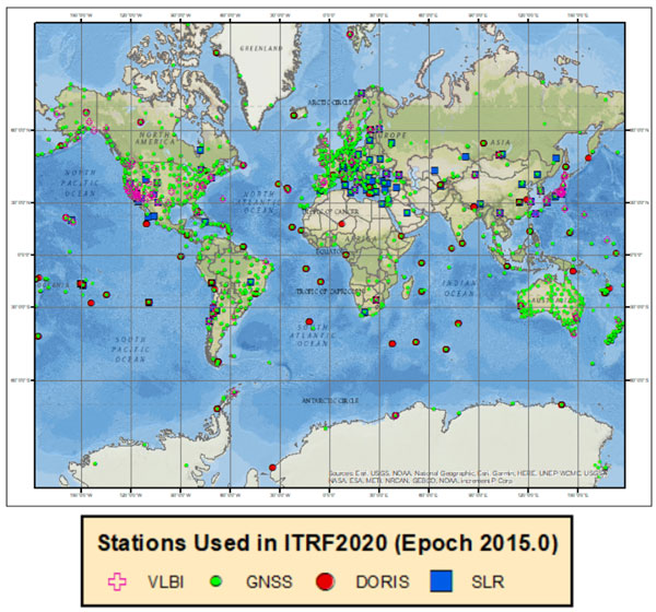
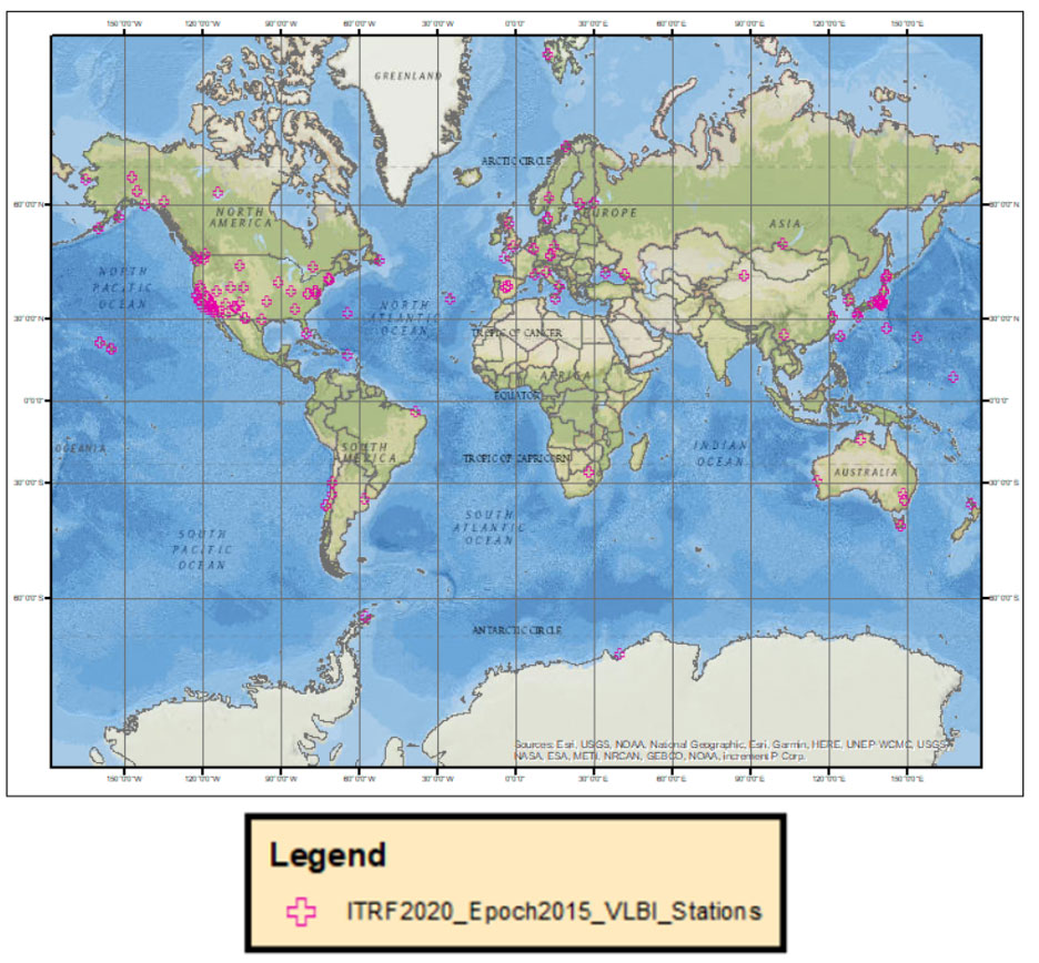
For this column, I downloaded the station lists from the four space geodetic techniques and provided a few plots that depict the location and velocities of these sites. The box below depicts the location of the space geodetic techniques around the world. As indicated in the plot, some locations have more than one technique collocated at the same site.
Plot of the Four Different Space Geodetic Techniques
Image: Dave Zilkoski
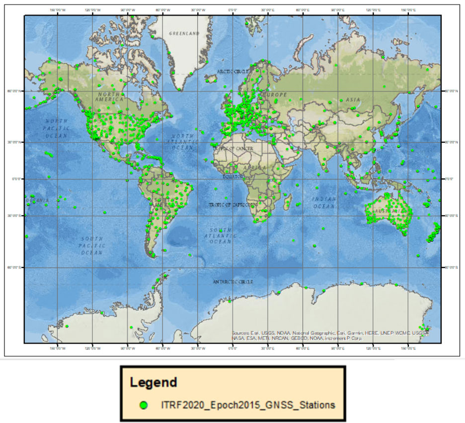
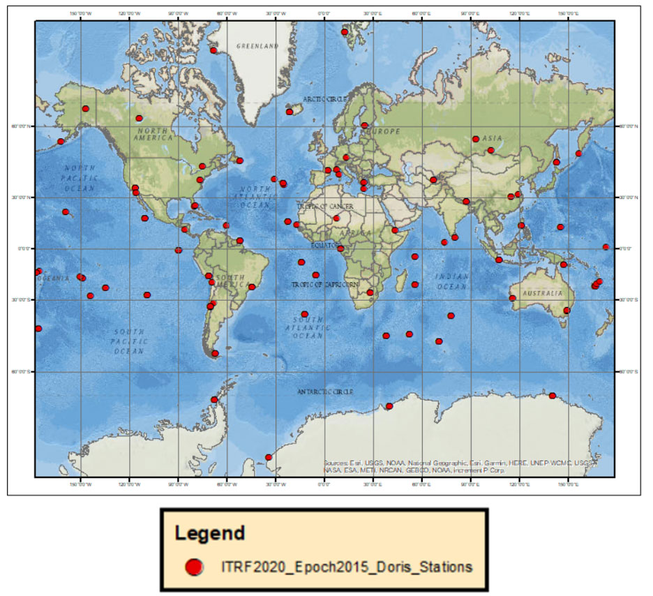
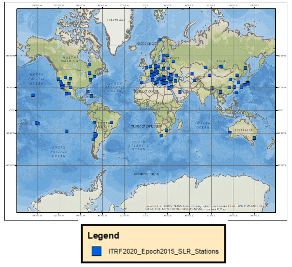
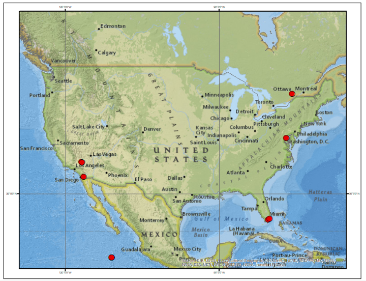
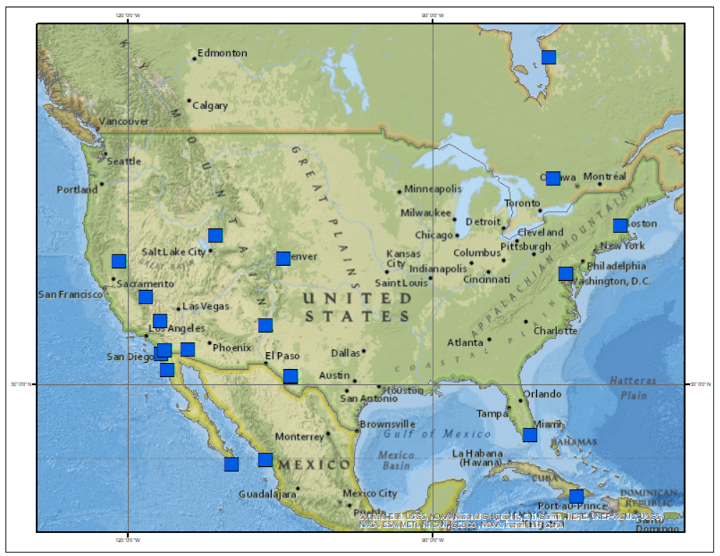
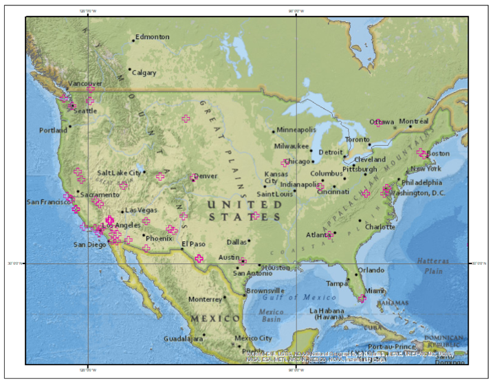
The following plots depict the locations using each space geodetic techniques: GNSS sites, DORIS sites, SLR sites and VLBI sites.
Plot of GNSS Sites
Image: Dave Zilkoski
Plot of DORIS Sites
Image: Dave Zilkoski
Plot of SLR Sites
Image: Dave Zilkoski
Plot of VLBI Sites
Image: Dave Zilkoski
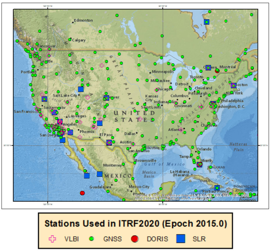
The box below shows the location of the techniques in the conterminous United States.
Plot of the Four Different Space Geodetic Techniques in the CONUS
Image: Dave Zilkoski
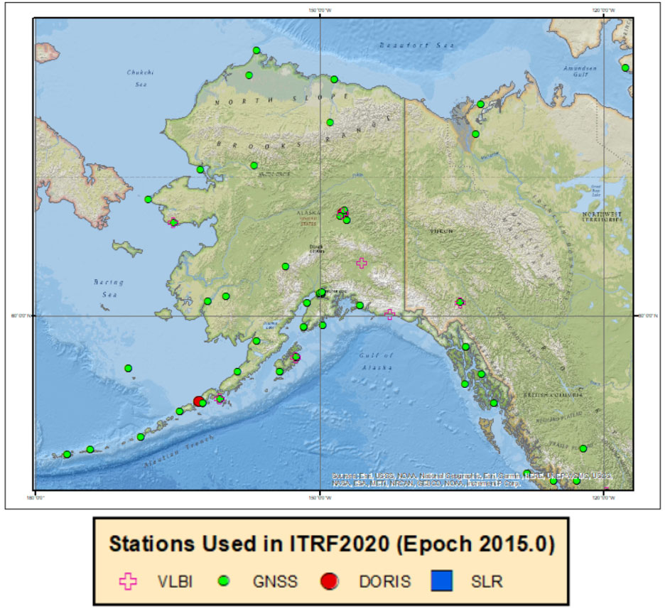
The plot below depicts the sites in the state of Alaska.
Plot of the Four Different Space Geodetic Techniques in the Alaska
Image: Dave Zilkoski
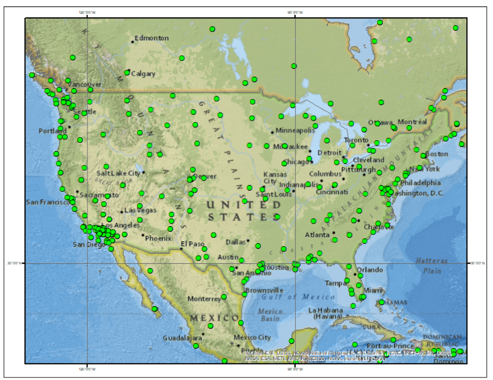
The images below depict each of the four space geodetic techniques in the conterminous United States.
Plots of the Space Geodetic Techniques by Technique in the CONUS
Plot of GNSS Sites in CONUS Image: Dave ZilkoskiPlot of DORIS Sites in CONUS (Image: Dave Zilkoski)Plot of SLR Sites in CONUS (Image: Dave Zilkoski)Plot of VLBI Sites in CONUS (Image: Dave Zilkoski)
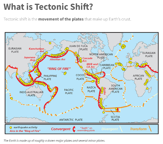
Altamimi’s article on the ITRF2020 stated it is “necessary to regularly update the ITRF (approximately every 5 years) to account for station position temporal variations due to geophysical phenomena.” My February 2022 column discussed the tectonic plates and why is it necessary to account for movement in a geodetic reference frame. As I stated then, coordinates basically change because the Earth’s surface is moving due to the movement of major tectonic plates. See the box titled “What is Tectonic Shift?” for information about why it is called plate movement or tectonic shift. The world’s geodesists understand this and are attempting to manage the changing coordinates by providing a time-dependent component of the international terrestrial reference frame.
Image: National Ocean Service websiteImage: National Ocean Service website
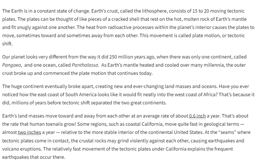
The box below depicts the horizontal velocity based on the ITRF2020 velocities (downloaded on 08/12/2022).
Plot of the Horizontal Velocity Vectors based on the ITRF2020 Velocities
Image: Dave Zilkoski
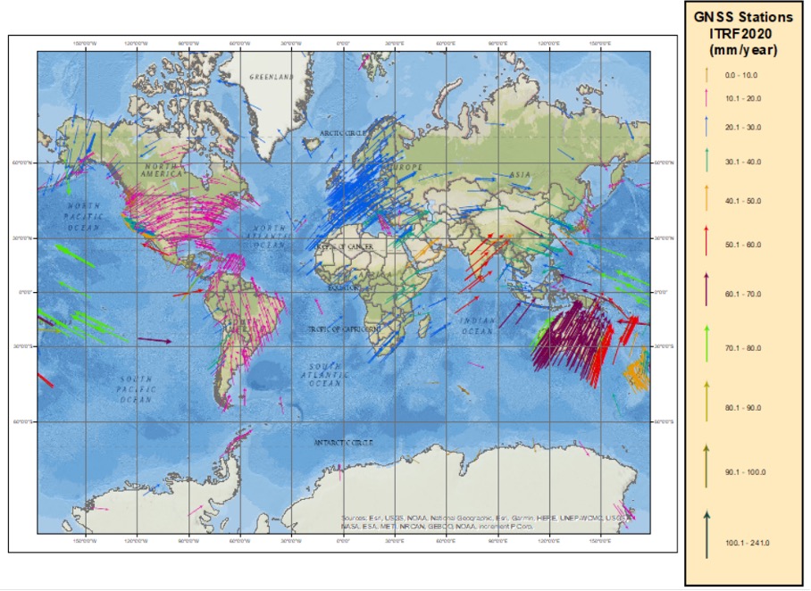
The box below depicts the horizontal velocities in the North America. These vectors look very similar to the velocities reported in my February 2022 column.
Plot of the Horizontal Velocity Vectors in North America based on the ITRF2020 Velocities
Image: Dave Zilkoski
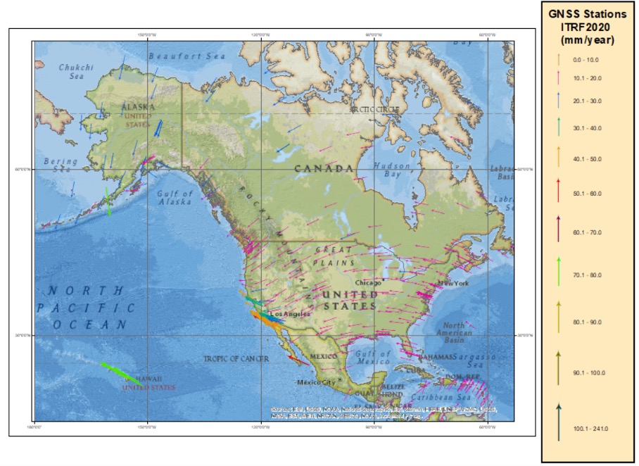
For a comparison to North America vectors, the box below depicts the velocity vectors in Europe.
Plot of the Horizontal Velocity Vectors in Europe based on the ITRF2020 Velocities
Image: Dave Zilkoski
They are similar in magnitude, but not in direction. Once again, looking at the map of tectonic plates, North America is located mostly on the North American plate and Europe is on the Eurasian plate.
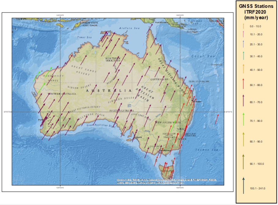
Australia is on the Indo-Australian plate and has some fairly large horizontal velocities vectors. See the box below.
Plot of the Horizontal Velocity Vectors in Australia based on the ITRF2020 Velocities
Image: Dave Zilkoski
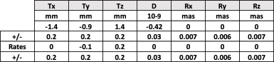
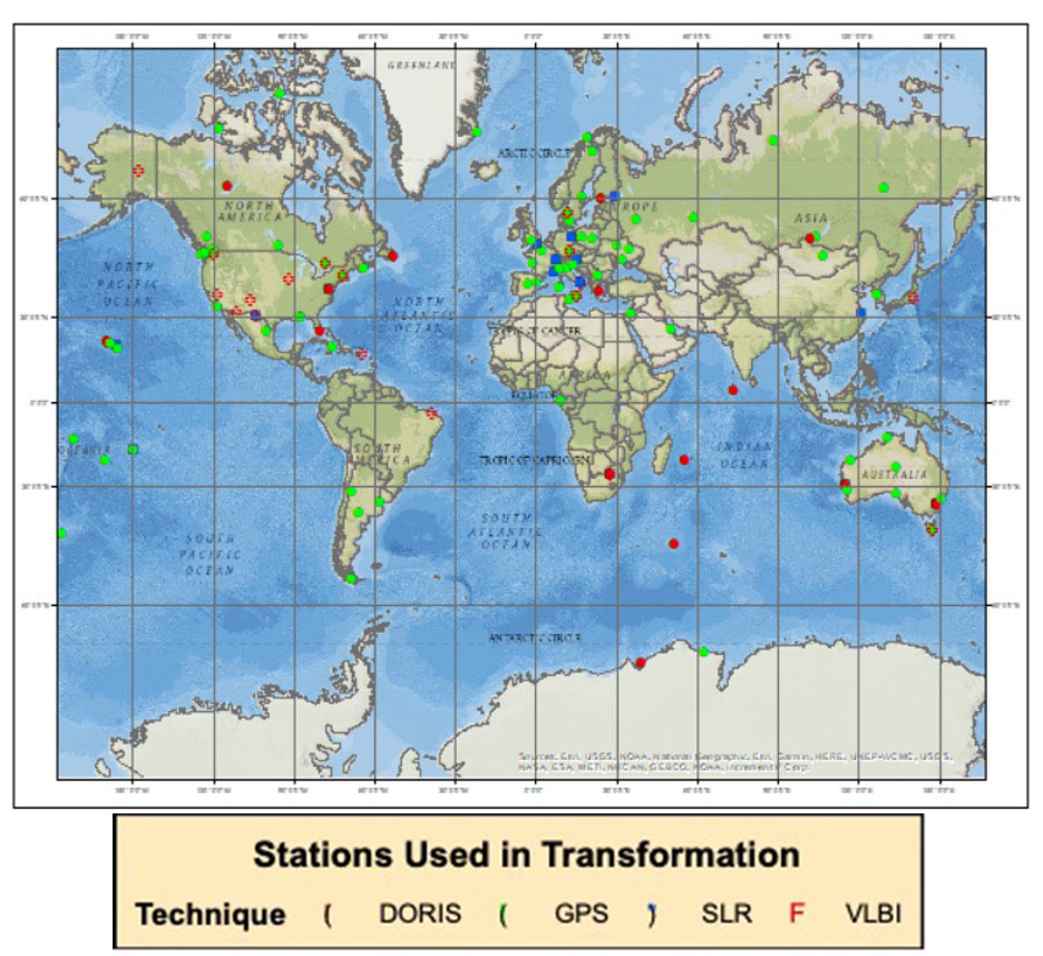
So, what’s the difference between ITRF2014 and the new ITRF2020? The box below provides the 14 transformation parameters from ITRF2020 to ITRF2014. These transformation parameters have been estimated using 131 stations located at 105 sites. See the box “Plot of the Stations used in the Transformation Parameters from ITRF2020 to ITRF2014” for the location of these stations. Notice that the translation values in X,Y,Z are very small (<1.5 mm) between the two reference frames.
Transformation Parameters from ITRF2020 to ITRF2014
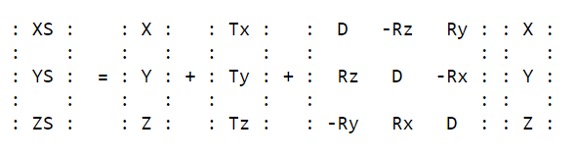
X,Y,Z are the coordinates in ITRF2020, and XS,YS,ZS are the coordinates in ITRF2014.
Plot of the Stations used in the Transformation Parameters from ITRF2020 to ITRF2014
Image: Dave Zilkoski
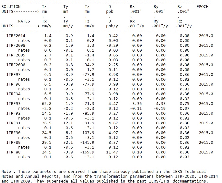
The transformation parameters from ITRF2020 and past ITRFs are provided in the table below. As indicated in the table, most of the changes in X,Y and Z are very small since ITRF2005.
Transformation Parameters from ITRF2020 to Past ITRFs
As previously stated, the third multi-year CORS solution will be important to the new 2022 modernized National Spatial Reference System (NSRS) because NGS will establish a strict mathematical relationship between the 2022 NSRS frames and the ITRF2020 frame. This will allow direct access to the NSRS, according to NOAA Technical Report NOS NGS 67. Again, there will not be any changes to NGS’s NOAA CORS coordinates due to ITRF2020 until NGS completes its third multi-year CORS solution.
Users can receive emails about the latest NGS News by signing up for NGS’s newsletters. These notices will highlight the release of new products, updates to existing services, progress reports for major projects, information about upcoming NGS-sponsored events, and job opportunities at NGS.