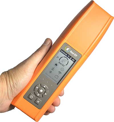
Bad Elf LLC has completed transition of all Bad Elf Flex receivers to the Hemisphere GNSS Phantom OEM module.
Photo: Bad Elf
As one of the first partners to incorporate the Phantom, Bad Elf Flex offers significantly enhanced capabilities and further exemplifies the company’s commitment to future-ready GNSS designs.
“We tested the Phantom OEM modules extensively, and confirmed they deliver the promised power savings and performance improvements when integrated with the Bad Elf Flex,” said Larry Fox, Bad Elf’s vice president of marketing and business development. “Hemisphere’s technology allows us to democratize GNSS through Bad Elf Flex.”
The new Phantom modules deliver a 30% gain in battery life, superior performance and scalable access to every GNSS constellation and signal, including GPS, Galileo, GLONASS, BeiDou, QZSS, IRNSS, SBAS and Hemisphere’s Atlas L-band, Fox said.
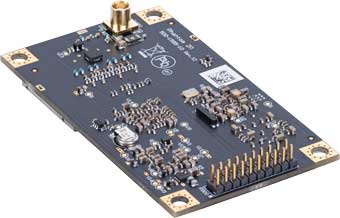
Photo: Hemisphere GNSS
Bad Elf Flex is a scalable-accuracy GNSS receiver with a daily option to choose between L-band and real-time kinematic (RTK). In standard configuration, it achieves 30-60 cm accuracy in real-time for GIS use.
Consuming a Bad Elf Flex Token unlocks a full RTK workflow for a 24-hour period to deliver 1-cm horizontal accuracy. Bad Elf Flex stores the tokens directly on the receiver, making them available for use anytime and anywhere. Customers requiring high accuracy at all times can purchase the Bad Elf Flex Extreme bundle, with RTK capabilities permanently unlocked, for a one-time upgrade fee.
Surveyors and their crews now have a scalable-accuracy, survey-grade receiver. GIS managers can focus on flexible field choices for work crews with varying skill levels. Bad Elf Flex falls within most capital expense budgets, allowing businesses to obtain operational and financial efficiencies.
“Bad Elf saw an opportunity to offer the GIS community a product lineup with better than 3-meter accuracy for under $3,000,” said John Cunningham, Bad Elf’s chief executive officer. “We began three years ago with our 2-meter ($300) and 1-meter ($600) mapping-grade product offerings. Our customers continued asking us to address the 50 cm, 10 cm and 1 cm requirements for their businesses. We worked hard over the past two years to build a platform, Bad Elf Flex ($3,000), that addresses these needs without breaking budgets. We have a solution that works today and provides a foundation to meet future customer requests. We love learning from our customers and look forward to continuing this conversation and extending high-accuracy GNSS for all.”
“Hemisphere is excited that Bad Elf’s Flex series now features our latest generation GNSS receiver,” said Miles Ware, director of marketing at Hemisphere. “We believe the scalable accuracy option made possible by our high-performance Atlas L-band correction service will be a game-changer in their served markets.”
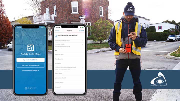
Eos will announce compatibility of its Arrow GNSS receivers with the inaugural ArcGIS Field Maps beta release, the expansion of Eos Locate underground mapping locator-device compatibility, as well more exciting updates for users of high-accuracy GPS with ArcGIS apps.
Eos Positioning Systems, manufacturer of the high-accuracy Arrow Series GNSS receivers for the GIS market, has announced several new releases ahead of the 2020 virtual Esri User Conference.
The announcements include the expansion of the availability of the Eos Locate
underground mapping solution, compatibility with the new ArcGIS Field Maps, the inaugural release of Eos Tools Pro for Windows, and a “special surprise” for virtual attendees of the 2020 Esri UC.
Image: Eos Positioning
Expansion of Eos Locate
Eos Locate is a high-accuracy, real-time underground mapping solution for Esri
ArcGIS apps users. It allows organizations to accurately map already-buried assets straight to ArcGIS Online via either ArcGIS Collector or ArcGIS Field Maps.
Eos has expanded Eos Locate compatibility with additional models from Vivax-Metrotech, Subsite and Radiodetection.
Compatibility with ArcGIS Field Maps beta
ArcGIS Field Maps is the newest Esri mobile application, which combines the functionality of several existing Esri mobile applications, such as ArcGIS Collector, ArcGIS Explorer, and ArcGIS Tracker.
The ArcGIS Field Maps beta release this month is already fully compatible with Arrow GNSS receivers (all models). This means organizations with Arrow GNSS receivers can immediately start taking advantage of survey-grade Arrow GNSS locations and metadata within ArcGIS Field Maps for data collection, markups, read-only routine field work (e.g., utility locates), GPS tracking, and more.
In addition, two Eos solutions previously exclusive only to Collector also already work with ArcGIS Field Maps. These include:
Eos Tools Pro is a free GNSS monitoring application for Arrow GNSS receivers. For the first time, this app is now available for Windows 10 users.
Eos Tools Pro allows fieldworkers to:
Connect to an RTK network or base station via NTRIP
Get elevations in orthometric heights via geoid model conversions in real time, in the field (directly into an Esri app)
Apply a simple X, Y, Z datum shift to the current location to match any local datum
Set a vast number of audible alarms
In addition, developers using Windows 10 will now be able to access the wide array of Arrow GNSS metadata while eliminating the task of parsing NMEA data.
Finally, Eos Tools Pro features a built-in duo of virtual Com Port and TCP/IP server to output streams of standard NMEA sentences. This enables multiple apps to have simultaneous access to the Arrow GNSS location and metadata.
Special surprise for eligible 2020 Esri UC attendees
In support of the inaugural virtual Esri UC, Eos is offering a one-time-only chance to win an Arrow 100 submeter GNSS receiver. To enter to win, eligible attendees must both
Complete a meeting with an authorized Eos representative during the 2020 Esri UC (July 13-16), which can be achieved by visiting the Eos virtual booth (V103), and
Fill out a special contest contact form made available by that representative.
Both the meeting and special contest contact form submission must be completed no later than July 16.
The following people are not eligible to win: Employees of Eos and Eos distributors, employees of Esri and Esri distributors, employees of other exhibiting/sponsoring companies, employees of other GPS manufacturers or vendors, registered media, and others whom we deem to have a similar affiliation.
Visit the Eos virtual booth (V103) to talk with sales, marketing, and technical support staff during the event expo hours.
Intergeo 2020, originally slated to take place Oct. 13-15 in Berlin, Germany, will now take place entirely virtually. Organizers announced in early June that the show would take place partially in person and partially virtually.
“Due to international travel restrictions, the protection of risk groups and the limited possibilities of people coming together in enclosed spaces, the Intergeo 2020 in its diversity and size is not feasible under the usual circumstances,” organizers said in an email to registrants.
Berlin recently reduced the number of participants of indoor events to 1,000 people, making the show — which attracted more than 20,000 participants in 2019 — unfeasible.
Now called INTERGEO 2020 Digital, the conference will facilitate the transfer of knowledge and exchange of ideas as well as providing “accessibility and opportunity to drop in at the exhibitors.”
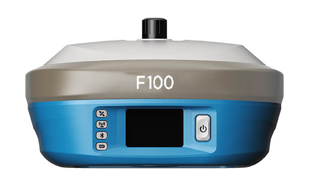
Geneq Inc.’s new F100 GNSS receiver, an upgrade to the F90, is designed to meet surveyors’ demands for high field performance, flexibility and cost-effectiveness.
The F100 tracks multiple constellations (GPS, GLONASS, Galileo, Beidou) and can maximize the acquisition and tracking process with all-in-view GNSS frequencies.
Another important feature from the F100 is the 1.45-inch color LCD display with a multi-touch capacitive screen. It has 32GB of internal memory. Its integrated second-generation web user interface control is compatible with all devices and all browsers.
Photo: Geneq
Providing maximum performance for accuracy and real-time measurements, F100 also supports real-time kinematic (RTK) correction services, including the RTX service that can get centimeter-level accuracy without a base station. The F100, with its advanced technology, ensures high performance even in difficult environments such as under heavy canopy.
The F100 has an excellent combination of GNSS, 4G, Bluetooth and Wi-Fi antenna. The innovative F100 has a built-in 5-watt radio that enables an effective baseline of 10 kilometers.
Its shorter charging time and a battery of 13600-mAh capacity enable long hours in the field. Even with its magnesium alloy casing, F100 weighs only 1.5 kg and measures 154 x 154 x 76 millimeters. Mobile field workers will find in this feature an ally to their surveying productivity.
With its integrated high-sensitive E-bubble and new tilt survey algorithm, the F100 becomes a calibration-free GNSS receiver. Immune to magnetic disturbance and free from limitation of tilt angles, the F100 can be used to measure unreachable points.
Everywhere we look, data is being collected, reviewed, analyzed and stored. It used to be that data was a static piece of information, like a piece of paper in a filing cabinet. Millions of pieces of data being created yet almost all of it never to be used again. The computer and electronic storage began a revolution of how we warehouse this information but that was only the beginning. Technology has turned data into a living, breathing beast few understand yet it controls most of our lives in various ways.
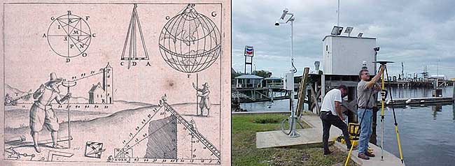
Mapping of the earth has not always been about establishing boundaries and parcels; many of the early maps and plats were created to depict the topography of our world. While there are some indications that Middle East maps depicted parcels, the first examples of topographic maps were created during the Roman Empire era of 300 A.D. It is common knowledge that the Romans utilized primitive yet cunning engineering for roads, buildings, and waterways but it was the initial topography that was mapped that allowed them to design those forward-thinking infrastructure components. Because of the lack of sophistication in the measuring methods and data collection, these topographic maps covered small areas and often crude because of the materials available. Considering what they were working with, it is still incredible what they were able to map, design and build.
Measuring devices and methods of data collection expanded over the centuries like most occupations and professions. By the 16th and 17th century, mathematics has been introduced at a wider scale through many educational facilities. Another profession, geographers, also advanced with the evolution of measuring devices and mapping techniques. It was during this period that we began to see a crossover with surveyors with geographers to create topographic maps with greater accuracy and precision through triangulation.
In the 18th and 19th century, instruments became more sophisticated to assist in the determination of elevations and more accurate angle measurements. The concept of triangulation flourished during this period and significant mapping was made for most of the civilized world. The early 1800s saw the westward push of expansion in the United States and Thomas Jefferson, U.S. president and former surveyor, led the charge to map the existing states and divide the west into sectional land for sale to settlers.
Besides the establishment of the Public Land Survey System, surveyors also provided topographic information for map of all sizes for future development planning. The late 1800s brought a large amount of topographic mapping information to paper through efforts by the U.S. Geological Society to map the entire United States. This information has been called the first land database; although crude in overall nature compared to today’s standards, it contained an enormous amount of topographic information.
These surveys continued well into the early 20th century until a revolutionary invention coupled with a current technology merged: the use of a mounted camera taking aerial photographs from an airplane. Geographers and photogrammetrists were able to use surveying data to assist with scaling orthometric photographs to create aerial images of thousands of acres of land. These aerial photos became the base layer for determining topographic features and contouring, covering much more land than ever before. Additional innovations included advancements in stereo plotting and photogrammetric techniques to further create high sophisticated topographic maps for the era. This type of mapping was the gold standard for decades depicting existing condition and topographic features for most of the world until the early 1970s and the computerized data revolution.
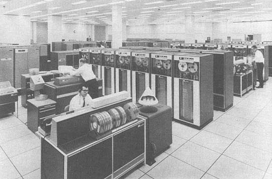
Computers take over the world (literally)
1960s mainframe computer (Photo: NASA)
While mainframe computers became more universally used in the 1960s, their use was contained to governmental agencies and large corporations. As the physical size of the computer reduced, the computing capacity increased, programming became easier to complete, and more applications were created to perform a variety of tasks. One of the biggest advancements for the era was electronic storage and analyzation of data through programming. Relational databases became a hot ticket for large datasets; geographic data was the perfect fit for this type of application. Modern mapping was on its way forward at warp speed.
Topographic mapping was not lost in this shuffle. The survey itself is based upon data points located on the face of the earth so each point is just another chunk of information within the database. Programming continued to advance and soon methods previous completed by manual methods over long periods of time were completed in a fraction of previous efforts without fail.
This effort was also joined with advancements in graphical technology to display this data on a computer video screen instead of lines of green text and numbers. Vector-based graphics, together with enormous point databases, helped create large topographical and geographical maps for many uses. During the same time the US put a man on the moon, mapping and platting of topographic information was also out of this world.
The turn of the century brings big changes
For the next decade, there were small advances in technology for topographic surveys and data points, but most were in presentation of data and increases in computing power. Pen plotters and smaller yet more powerful computers were becoming affordable to smaller companies, but it was still a large investment to get into the computerized data game for a surveyor. By the mid-1980s, electronic data collection with a total station was becoming the norm, but only meant collecting more points in a more efficient timeframe. The computing component did get faster but is still producing the same information of static data points.
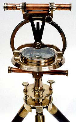
Ancient techniques and new technologies (Image: ngs.noaa.gov)
The mid-1980s also brought us a shiny new object: GPS technology. By the end of the 1990s, we were able to get out of our vehicle, start the receiver and collect geolocated points in minutes rather than hours. The big takeaway from this advancement is the geolocation component of the data point. Now everything can be related to one big dataset of topographical points. By creating a database with all our project data collected in the same georeferenced datums (horizontal & vertical), we can create digital models that replicate existing conditions.
We can also add another big advancement in data collection: remote sensing technology. From laser and lidar scanners, photogrammetry, SLAM technology and ground penetrating radar, the innovations to collect data at locations we can “see” through sensing are now a reality. Another significant improvement with this technology is the amount of data points remote sensing can collect, both in timing and spacing. We are now talking small scanning projects that consist of billions of points within the site point cloud. We are fortunate that our computing power and storage capabilities has increased exponentially along with the remote sensing. (Remember doing a “regen” on your CAD file and having time to get a cup of coffee?)
Lots of data — now what?
Data is powerful, especially when it is harnessed in a robust system that can analyze and model for future use. Yes, this condition also applies to the surveying world, even though you may not be thinking about it now. We can use this data to create a virtual world that mimics the one we live in; the difference is that we exist in ours yet model and manipulate the digital version in our computer system. The technology is now available, and we can make a replica of our current world; however, why would we want to do that? There are lots of reasons to use technology and data to make sophisticated topographic maps (because that is what they are) for recording the world around us.
One of the big differences now is that we have much more information about the data points we collect within our topographic maps. Sure, many surveyors will say that their data has not changed or evolved during their careers, but they would be wrong. Unless they are still manually writing it all down for hand plotting… (Hello! The 1960s called, and they want their field book back!) Every electronically collected point has attributes associated with the data.
These attributes, while they may be simple, contain important information about the datapoint it represents. Horizontal location? Check. Vertical elevation? Check. Assigned point number? Probably. Field code? Most likely. But it also has one other important component: time. We now know exactly when that point was collected. Why is that important?
Because, like a lot of instances, things change. Something collected today might not be there tomorrow. Time is just as important as the physical location and the type of point it represents.
Gather these points together, throw them in one big model and you have yourself a graphical database that can be analyzed, reviewed, and used for planning and design. It may be hard to visualize with just simple survey data using GNSS and/or a total station, but couple it with a scanner or photogrammetry, you have a powerful hunk of data for which to work.
Why is this workflow and modeling procedure important enough to dedicate an entire column about surveying and GNSS to? Because it used to be far in the future, but the need and availability to use it is now here in front of us. Surveying and GNSS are an important part of this effort to create three dimensional models. By using survey-grade data in conjunction with point clouds collected from remote sensing equipment, we can replicate the world around us in real time.
Yes, Virginia, there is a name for the modeling process…
Photo: iStock.com/alexsl
The name for the proposed modeling of this dataset is a digital twin. It represents a digital representation of a physical object or system. NASA famously used the concept for their space program to simulate situations and procedures of many different types of events. The concept has grown with the technology to graphically create almost anything through digitalization and computer modeling. Once the model is created, both actual and proposed data points can be included to represent the existing and future opportunities.
The idea of a digital twin is not new; technology, however, has pumped more life into its existence by leaps and bounds with computing power and data storage capability. I remember, early in my career, going into an architect’s office and seeing the scale model mockup of a new development or building. The streets in the model were perfect, there were no drainage issues, and it was a neat as a pin. Fast forward to the construction of the development and field changes were at every turn. A digital twin will allow for better planning, more thorough design and creating more cost-effective development. Many large cities have started compiling data and building their digital twin, including New York, Singapore, Boston, and Rotterdam. Engineering and planning for new and replacement facilities is very expensive yet analysts predict that having a digital twin to work will save a significant amount of money and time.
As a surveyor, what’s in it for me?
Software capability for the surveyor is already here. Companies, such as Hexagon, Trimble, Topcon and Esri to name a few, have been developing their software to accommodate this concept for many years. Still, lots of surveyors do not know about it. And we should. Many of us live in places where the infrastructure is well past its useful life period and should have been replaced long ago. By starting now with survey-grade data to be put into a real-time model, we can help our governmental agencies and their consultants to move towards a digital twin that will ultimately save money and possibly lives.
What this means for the surveyor is to further embrace technology and include remote sensing into your operation. If you have not started at least looking into UAVs and photogrammetry, you are already behind. Many aerial operations are making the next leap into mounting a LiDAR unit on their UAV to gain even more capability. Early adopters of laser scanners were probably second guessing their decision during the 2008 Depression but if they stayed with it, it will be a big payoff in the long run. The next leap will be into handheld scanning devices, including ones using SLAM (simultaneous localization and mapping) technology for locating interior and close-up improvements. These technologies will cost a significant amount of time and money to implement but municipalities, engineers and architects are going to be clamoring for the data any day now.
When it comes to surveying and mapping of existing facilities, the surveyor and technology makes a great team. Do not let point clouds, remote sensing, or terabytes of data scare you away from providing badly needed information to help assemble your local digital twin. In the long run, it will pay off for all who take on the challenge of building it.
A new Esri mobile app, ArcGIS Field Maps, will be released in its first beta in July, with the final version expected to be released in September.
According to Esri, Field Maps will combine the following capabilities into a single app:
Simple map viewing and markup
High-accuracy field data collection and inspection
Battery-optimized location tracking
Work planning and task management
Turn-by-turn navigation
Field Maps also will include a new web app, integrated with ArcGIS, that can be used to configure and deploy maps optimized for your mobile workforce needs, create and assign tasks to mobile workers, and create and share views of worker locations.
Arrow support included
The inaugural beta includes support for Arrow GNSS receivers’ high-accuracy locations, elevations and metadata, according to Eos Positioning.
ArcGIS Field Maps will provide the combined functionality of five Esri mobile apps: ArcGIS Collector, ArcGIS Explorer, ArcGIS Tracker, ArcGIS Workforce and ArcGIS Navigator.
In the first beta version, users will be able to perform markups, work with read-only maps, and work with MMPKs, including high-accuracy GPS locations and metadata from Arrow GNSS receivers.
Photo: Eos Positioning
Customers who have been wanting to take advantage of high-accuracy GNSS data in apps such as Explorer and Tracker will now be able to with the beta release. Customers who would like to have field crews able to access read-only maps with high-accuracy, for instance (such as during utility locates), this is now a possibility. In addition, crews can take advantage of high-accuracy GPS tracks while tracking.
ArcGIS Field Maps will also support the two formerly Collector-exclusive Eos solutions Eos Locate and Eos Laser Mapping.
Eos Locate. This high-accuracy underground mapping solution will be available in ArcGIS Field Maps right away in the first beta release. A single fieldworker will be able to perform real-time, high-accuracy mapping of underground assets using the same workflow he or she had previously used with Collector and Arrow GNSS.
Eos Laser Mapping. Similarly, laser offsets with Arrow GNSS receivers and LTI laser rangefinders will be available in the first beta of ArcGIS Field Maps. Learn more about laser offsets, including the three workflows for using them, here:
“We are incredibly excited for the new opportunities ArcGIS Field Maps brings to expand our partnership with Esri,” Eos CTO Jean-Yves Lauture said. “Now our joint customers will be able to use the Arrow GNSS receivers with Field Maps to access high-accuracy location when simply viewing and marking up maps and when logging location tracks.”
Eos Positioning told its customers, “We encourage all Eos customers currently using Collector, Tracker and/or Explorer to join the beta. Meanwhile, Collector, Tracker and Explorer are planned to continue working as usual, according to the roadmap Esri has outlined.”
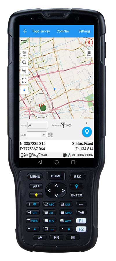
ComNav Technology has released the new-generation data collector R550.
With its new industrial-level design and new hardware platform, the R550 is designed to ensure efficiency and productivity in the field.
The IP67 dust-and-waterproof rating protects the R550 from most harsh environments. Equipping it with 7,000 mA Li-ion battery allows more than 14 hours of continuous operation, while fast-charging technology means it only takes four hours to fully charge the collector via the type-C interface port.
The 5-inch-wide sunlight-readable, high-resolution screen provides a smooth experience for any operation. The integrated autofocusing camera helps enhance job documentation by taking photos on site and sharing job information with colleagues.
Survey Master field software available on the R550 controller ensures efficient surveys in the field, including topographic surveys, stakeouts, coordinate geometry (COGO) and more.
Powered by the Android 8.1 operating system and designed with 4G RAM, 64GB ROM and 4G/BT/Wi-Fi on board, users can run other third-party apps based on their specific requirements.
The R550 data collector now is available through ComNav Technology authorized local distributors or ComNav Technology directly.
Lidar series paired with professional drone provides multi-platform, high-accuracy 3D laser scanning for geospatial and mapping professionals
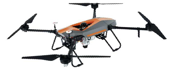
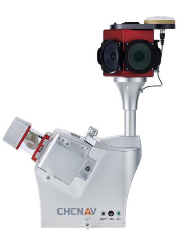
CHC Navigation (CHCNAV) has launched the multi-rotor BB4 drone and AlphaUni 300/900/1300 lidar.
Photo: CHCNAV
The combination of the AlphaUni 300/900/1300 lidar and BB4 UAV solutions creates a comprehensive and versatile range for 3D mapping and geospatial data acquisition in land, air and marine applications.
“The purchase of a 3D mobile mapping system is too often constrained to a specific purpose, such as airborne or ground survey,” said George Zhao, CEO of CHCNAV. “A lot of our customers expressed the need to have a professional lidar solution that can be used in different scenarios, offering optimal adaptability to their current and future needs.
“With our AlphaUni series, we are now introducing an innovative response with a multi-platform lidar system that can be used with an aerial or marine drone, on a vehicle or carried as a backpack,” Zhao said. “In addition, the long flight autonomy of our new BB4 UAV allows missions over large areas in a single flight for exceptional productivity.”
AlphaUni lidar series
Photo: CHCNAV
The new AlphaUni series enhances CHCNAV’s Alpha Mobile Mapping family with a light, versatile long-range laser scanner systems available on the high-end market.
The series provides optimized data sets powered by advanced GNSS/inertial navigation system (INS) sensors and long-range Riegl scanners.
AlphaUni’s design adapts to a variety of applications and can be installed on a variety of platforms, including multi-rotor UAV, fixed-wing vertical-takeoff-and-landing (VTOL) UAV, vehicles, rail trolleys, backpacks, boats and more.
BB4 UAV
The BB4 UAV is a high-end multi-rotor drone optimized for the CHCNAV AlphaUni 300/900/1300 lidar series. Its modular design simplifies deployment in just a few minutes.
Its 7-kg payload breaks the capacity barrier, and more than 45 minutes of flight time increases the airborne lidar survey ability.
The redundant CHCNAV and DJI inertial measurement unit (IMU) and GNSS units provide reliable centimeter real-time kinematic (RTK) positioning, meeting the demand for high accuracy in the geospatial and mapping industry.
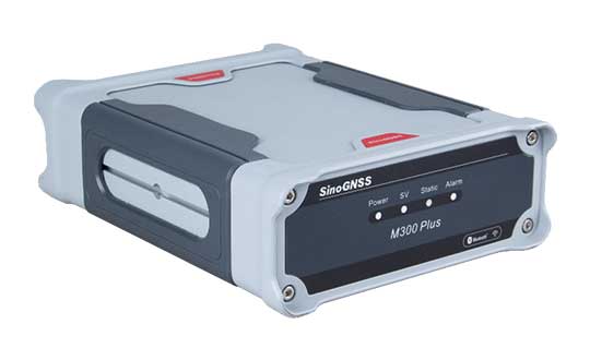
ComNav Technology has released the M300 Plus GNSS receiver to the international market.
The M300 Plus is designed to supplement the company’s M300 Pro, which is aimed at clients who need a more economical version for their CORS networks. The M300 Plus not only can be used as a CORS receiver, but is a good choice for monitoring projects and other applications.
With ComNav Technology’s new-generation GNSS engine, the M300 Plus can track all current and future constellations. By using a powerful, adaptive detecting and canceling technology, the M300Plus provides enhanced anti-jamming capability, which is critical for a reference station providing reliable GNSS data.
Photo: ComNav
The M300 Plus’ powerful built-in web server provides full remote control of the receiver configuration, status checking, firmware update and data download. It supports multiple independent data transfer through TCP/UDP/Ntrip protocol in RTCM, ComNav binary, NMEA and BINEX data formats, combined with Email Alert and FTP push, which improves the efficiency and profitability of businesses.
In addition to its standard Ethernet port for data transmitting, the M300 Plus GNSS receiver also fully implements a 4G module as an internet backup, which enhances the stability of data connections.
M300 Plus is now available through ComNav Technology authorized local distributors or ComNav Technology directly.
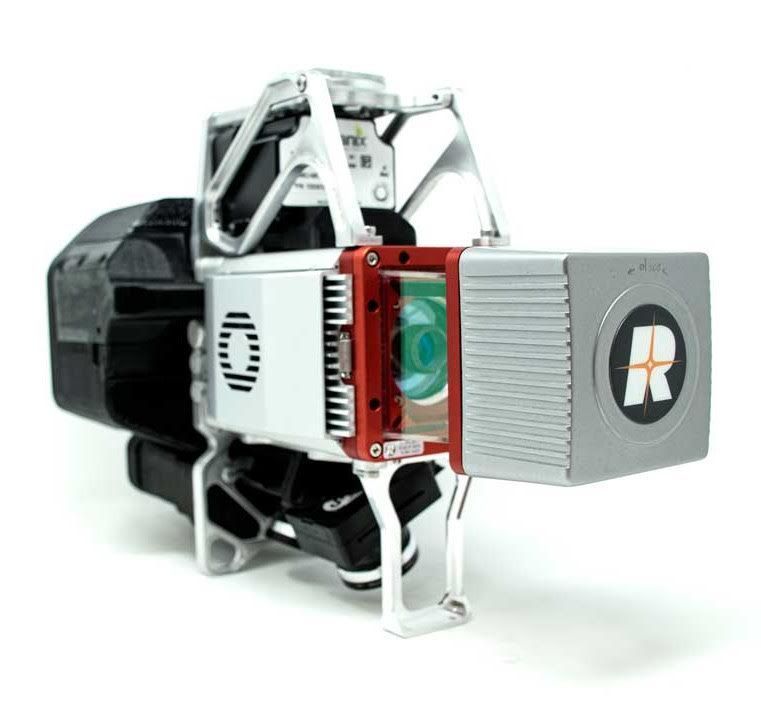
GeoCue Group has released the True View 615 and True View 620 UAS lidar 3D imaging systems. The True View systems are compact, survey-grade 3D imaging sensors designed for small unmanned aerial systems.
True View 615 and 620 are equipped with Riegl’s miniVUX-2UAV laser scanner integrated with dual photogrammetric cameras. Position and orientation is provided by an Applanix APX-15 (True View 615) or extreme accuracy APX-20 (True View 620).
All True View 3D imaging systems are bundled with Applanix POSPac, True View EVO post-processing software and True View Reckon data management solution.
The Riegl laser scanner and dual photogrammetric cameras have been carefully configured to provide a fused lidar/imagery field of view of up to 120°. The system includes full post-processing software that generates a stunning ray-traced 3D colorized point cloud and geocoded images.
An upgrade path will be available to promote a True View 615 to a True View 620 by adding the Applanix APX-20 external inertial measurement unit.
The True View product line gives mappers and surveyors the ability to deliver high-quality analytic data with exact accuracies. These deliverables are generated using workflows and tools within GeoCue’s post-processing software, True View EVO. Examples of derived products include bare Earth models, profiles, cross sections, topographic contours, volumetric analysis and more.
“Our Quanergy-based True View 410 has rapidly become the standard for general purpose drone 3D Imaging, where moderate vegetation penetration and accuracies of 5 cm RMSE are adequate,” said GeoCue’s President, Lewis Graham. “The True View 615/620 provides a solution for situations where deeper vegetation penetration, wire extraction and extreme accuracy are required. These are great new additions to the True View product line.”
The True View 615/620 will be available for shipment late June.
Australia-based Position Partners has launched MiRTK, an open architecture corrections service for GNSS equipment.
Internet-enabled, MiRTK offers an alternative to UHF radio correction services for high-accuracy GNSS. Unlike UHF radios, MiRTK is not limited by range from the GNSS base station and does not require line of sight with the survey rover or machine.
MiRTK uses a small modem that slides onto the accessory slot of the tripod and connects to the base station via a single cable.
A subscription service is available in locations with the Telstra network, mainly continental Australia.
MiRTK is designed for accurate GNSS positioning in the construction, mining and geospatial industries. It is compatible with all brands and models of GNSS from manufacturers including Topcon, Trimble, Leica Geosystems, Sokkia, Hemisphere and more.
“Until now, users that rely on high-precision GNSS for applications such as surveying and machine control had no option but to use UHF radios or a network RTK solution,” said Cameron Waters, geospatial business manager at Position Partners.
“Anyone that’s had to rely on UHF radio frequencies will have experienced problems, including interference, range limitations, costly licensing and severe penalties for breaching licensing laws. MiRTK offers an alternative that is refreshingly simple: no repeaters, no line of sight issues and no complex licensing,” he added.
The Galaxy lithium mine in Ravensthorpe, Western Australia. (Photo: jasonbennee/iStock / Getty Images Plus/Getty Images)
Another benefit, according to Waters, is the ability to utilise a single correction protocol across all GNSS equipment on site. This dramatically reduces complexity and potential connectivity issues. “MiRTK uses NTRIP and a user selectable format such as RTCM3 or CMR, that can be used universally regardless of the brand or model of equipment,” he said. “Users enjoy full speed, full constellation connectivity without the complex radio settings, baud rates, bandwidth or scrambling problems that you get when trying to utilize different GNSS systems with UHF radios.”
To set up the unit, users simply connect the modem to the base station, power the modem on and MiRTK will work for up to 20 hours continuously without charge. Each unit can connect with up to 10 devices such as survey rovers or machine systems as standard, with unlimited potential to scale up connections as required.
“The future of UHF is limited with lower bandwidth, higher density areas, increased governance, rising costs and little flexibility,” Waters said. “MiRTK gives customers a new approach to receive reliable correction data in a simple and hassle-free way, whilst utilizing their existing GNSS hardware.”
Driven by COVID-19, the uptick in adoption supports collaboration among remote workers as businesses adapt.
The Trimble Connect cloud-based collaboration platform has surpassed 10 million users. In response to COVID-19, distributed working has intensified the need for teams to share information and collaborate remotely, leading 1.2 million users to join Trimble Connect in March and April alone.
To date, Trimble Connect has hosted more than 80,000 design and construction projects, making it possible for people to collaborate and work together from anywhere in the world.
Photo: Trimble
Trimble Connect is an open collaboration platform for design and construction that connects project stakeholders with the data they need to inform decisions and improve team efficiency. Project stakeholders can share, review, coordinate and comment on data-rich constructible models, schedules and critical project information in real time — reducing costly miscommunication and improving coordination to keep projects on time and on budget.
In addition to adding new users, the activity on Trimble Connect has shown a considerable increase in collaboration for businesses in the architecture, engineering and construction (AEC) industry.
The number of invitations to collaborate on projects increased 58% in April over the previous month, indicating that users are adjusting to new remote and distributed working dynamics and enabling teams to stay resilient, despite interruptions to their traditional daily routines.
“This is an exciting milestone for Trimble Connect,” said Ray Bagley, business area director for Trimble Connect. “Businesses in the AEC industry need an open, common data environment that allows project stakeholders to unlock the real value of building information modeling (BIM), civil construction and geospatial data. The increased adoption of Trimble Connect in recent months shows us that businesses need reliable, open collaboration more than ever before.”
Trimble Connect’s open API enables data-flow to and from a variety of applications and allows users to customize workflows by integrating with existing enterprise solutions. Users can access project files stored on Trimble Connect directly through a wide range of solutions, including Tekla Structures software, Trimble Access field software, Trimble FieldLink layout software, SketchUP 3D modeling software and ProjectSight construction management software as well as third-party applications.