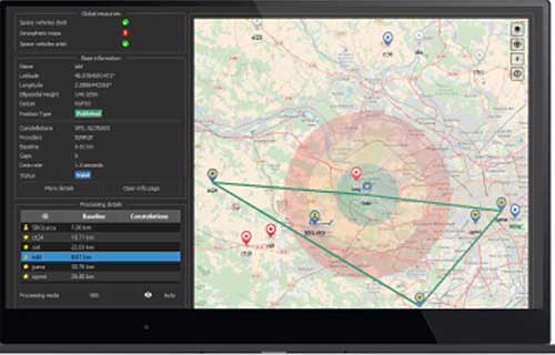
Qinertia, SBG Systems’ PPK software, now supports third-party IMUs and offers a GNSS post-processing license covering all major GNSS receivers
Screenshot: SBG Systems
SBG Systems’ INS/GNSS post-processing kinematic (PPK) software Qinertia now covers all surveyors’ projects by offering a license dedicated to GNSS post-processing. Open to the world, Qinertia supports all major GNSS receivers and is now open to third-party inertial measurement units (IMUs).
Qinertia has been designed to offer a comprehensive suite of post-processing software to geospatial professionals. It accepts all major GNSS manufacturers, and supports proprietary protocols from NovAtel, Septentrio, Trimble and u-blox for a straight-forward workflow.
The full-featured post-processing software offers native support for u-blox F9 real-time kinematic (RTK) receivers, reducing the workflow to a simple “drag and drop” to guarantee data integrity and accuracy.
Qinertia has been designed to help surveyors get the most of their surveys easily with a simple workflow, powerful quality control tools and tightly coupled algorithms. All of this is available to any surveyor with the new support of third-party IMUs or GNSS receivers. Several IMUs and inertial navigation systems (INS) have already been successfully integrated with Qinertia including Northrop Grumman’s LN-200 and LCI-100 and the Inertial Sense µIMU.
The new Qinertia GNSS license allows surveyors to post-process both static and kinematic GNSS data. In just a few clicks, surveyors can improve their trajectories, access RTK corrections worldwide, or even control a base-station’s precise location using precise point positioning (PPP) static computations.
GIS and Photogrammetry. Whether they fly a UAV or drive a car, professionals can improve their image location accuracy. Qinertia has been designed to help surveyors get their GIS or photogrammetry projects way more precise, by exporting a centimetric position for each picture at the exact shutter event.
A roundup of recent products in the GNSS and inertial positioning industry from the May 2020 issue of GPS World magazine.
SURVEYING & MAPPING
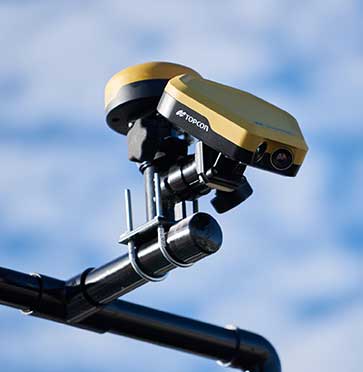
RTK thermal mapper
Asphalt paving with RTK positioning
Photo: Topcon
The Thermal Mapper is designed to monitor temperature segregation to prevent future problems and measure performance, as well as provide accurate compliance reporting, using real-time kinematic (RTK) positioning accuracy. It records temperature readings behind an asphalt paver during paving and provides a visualization to operators in real time of whether the mix falls within a predefined temperature range. If the readings are unacceptable, operators can make adjustments. The system also creates data reporting files to download for applications such as U.S. Department of Energy compliance through the interactive Pavelink module, the Topcon cloud-based logistics application for asphalt paving.
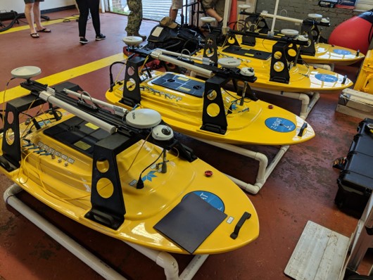
The Z-Boat 1800-T unmanned survey vessel is equipped with Trimble’s high-precision GNSS heading receiver and compatible with Trimble Marine Construction (TMC) software. The Z-Boat 1800-T enables marine construction and dredging projects to run efficiently and be monitored in real time anywhere in the world. The Z-Boat 1800-T is a high-resolution shallow-water hydrographic unmanned survey vehicle with the newly released Odom Hydrographic Echotrac E20 Singlebeam Echosounder and dual-antenna Trimble BX992 GNSS heading receiver. Each sensor is integrated into a compact, portable package for marine construction and allows data collection under harsh conditions. Both sensors can be removed and mounted on other watercraft and barges.
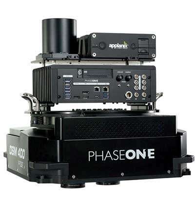
The 280MP Aerial Solution has an image coverage width of more than 20,000 pixels. The large format enables high-quality aerial surveys. Compact and lightweight, the aerial mapping solution consists of an iXM-RS 280F large-format camera, Applanix GNSS/inertial measurement unit (IMU) POS-AV receiver, DSM 400 Somag gyro-stabilized mount, Phase One iX Controller and iX Flight Management software. It is designed for use in a wide range of aircraft.
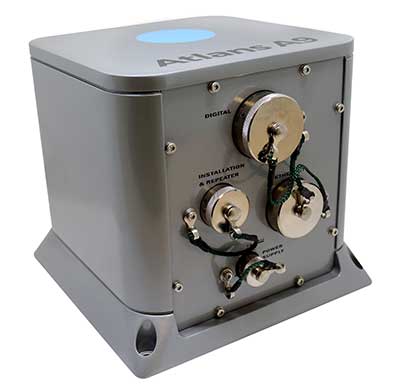
The Atlans Series of FOG-based inertial navigation systems (INS) is designed for land and air mobile-mapping applications. Based on iXBlue’s fiber-optic gyroscope (FOG) technology, the Atlans Series is a scalable range of north-seeking and north-keeping INS. They provide FOG performance to the full spectrum of land and air mobile-mapping applications and offer highly accurate positioning up to 0.01 meter in all conditions, including within GNSS-denied environments such as urban canyons, mountainous or forested areas.
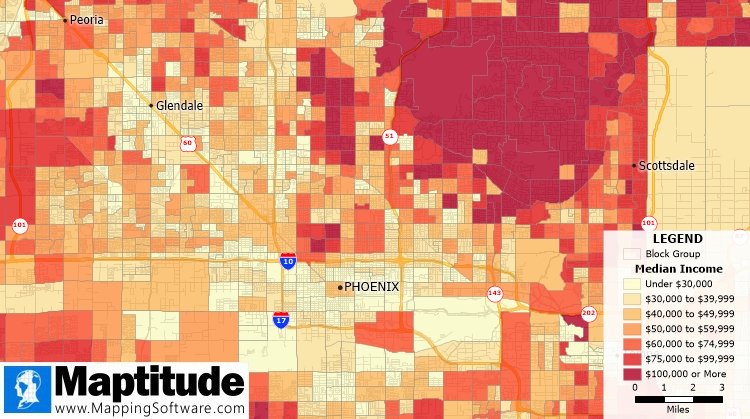
The Maptitude 2020 U.S. Census Blocks Groups data is now available for the United States. The small-area Census Summary Level is packed with neighborhood information for making accurate geography-based decisions. Users can explore locations by income, income growth, daytime population, age, race, gender, ethnicity, occupation, housing characteristics and more. The data can be leveraged by data scientists and market research analysts using the Maptitude application. The files are also available as shapefile, KML, KMZ or GeoJSON.
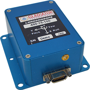
The high-performance LandMark 60 INS/GPS and compact LandMark 005 INS/GPS both feature advanced sensor-fusion technology, combining a 72-channel GNSS receiver with low-noise, high-output inertial sensors as well as barometric pressure and magnetometers. Both products use proprietary Velox processing technology and an extended Kalman filter (EKF), enabling precision position information during short-term GPS outages. The units provide accuracy of less than 2 nautical miles per hour during short-term GPS outages. The LandMark 60 provides +/– 0.3° heading accuracy and pitch/roll angle measurements of 0.1°. It is also available with an option for a real-time kinematic (RTK) GPS receiver. The LandMark 005 is less than 35 square centimeters, suitable for space-constrained applications that require a high standard of performance. Applications include flight control, navigation and stabilization for imaging, platforms and antennas. A development kit is available for set-up, configuration and data collection.
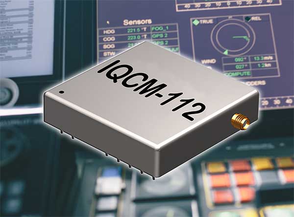
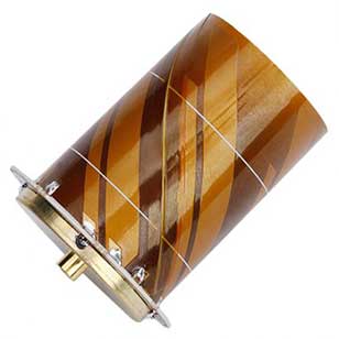
The IQCM-112 series of GNSS-disciplined oven-controlled crystal oscillators (OCXOs) incorporates an internal GNSS receiver with a 1-PPS output, which is compatible with an external GPS, GLONASS, BeiDou and Galileo source. It is housed in a 14-pin 60-millimeter-square package. When coupled to an external aerial antenna via the incorporated SMA connector, in the event of the loss of the GNSS signal the highly specified 10-MHz OCXO will switch in with a holdover capability of 1.5 µseconds for a 24-hour period, thereby maintaining lock until restoration of the reference signal. The standard operating temperature range of the module is –20° to 75° C, but it is also available with a –40° to 85° C operating temperature range. Other holdover specifications can be considered upon request.
The HC977 covers GPS/QZSS-L1/L2/L5, GLONASS-G1/G3, Galileo-E1/E5a/E5b, BeiDou-B1/B2/B2a, IRNSS-L5 and L-Band correction services, as well as GLONASS-G2. Tallysman helical antennas are designed for high-accuracy applications where precision and light weight matter, such as unmanned aerial vehicles. The antennas are available in either a robust IP67 enclosure or an embedded format. The HC977 features a low current, low noise amplifier (LNA) that includes an integrated low-loss pre-filter to protect against harmonic interference from high amplitude interfering signals, such as 700-MHz band LTE and other near in-band cellular signals.
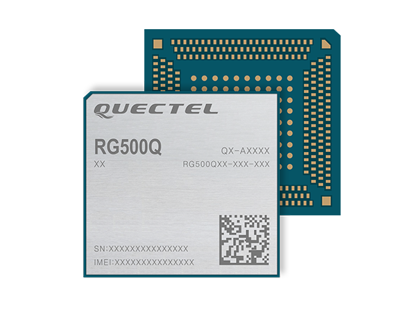
The RG500Q is a series of 5G sub-6-GHz modules optimized for internet of things (IoT) and machine-to-machine (M2M) applications. It supports the Qualcomm IZat location technology Gen9C Lite (GPS, GLONASS, BeiDou/Compass, Galileo and QZSS). The integrated GNSS receiver greatly simplifies product design and provides quick, accurate and dependable positioning capability. The RG500Q is provided in two variants: RG500Q-EA and RG500Q-NA. The RG500Q-EA 5G NR module has achieved commercial readiness and is now available to support global customers with mass deployment.
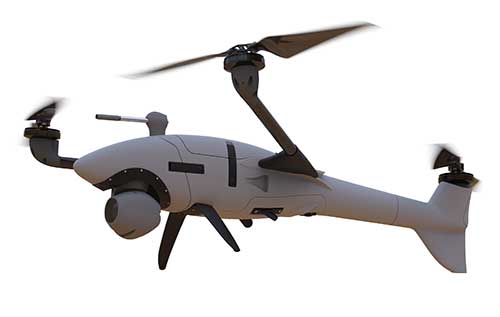
The V-150 is optimized for use from small naval vessels. It can be employed to support the homeland security, oil and gas and energy sectors. The UAV, which is free from International Traffic in Arms Regulations (ITAR) restrictions, incorporates two payload bays: up to 30 kilograms (kg) in the main bay and up to 12 kg in the nose. Within these, it provides a variety of payload options, including powerful electro optical and infrared (EO/IR) sensors, hyperspectral and multispectral cameras for airborne remote sensing, lidar and a variety of small tactical synthetic aperture radars (SAR) for delivering real-time intelligence in all weather conditions.
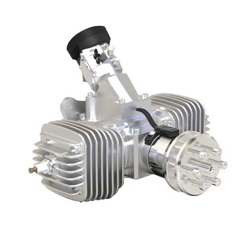
The SP-56 series is a family of small two-cylinder engines for UAVs. It can be integrated into small helicopters, which require smoother engine operation than single cylinders can provide. The SP-56 series provides 3.35 KW at 7,000 rpm; total weight of the carbureted version is 2.6 kilograms. The engine can be equipped with a generator or a starter generator on the rear output shaft. Hybrid applications are possible in which the engines are used only to generate electricity.
Two new small unmanned aerial systems (sUAS) are available to U.S. government defense and security markets. Vector and Scorpion form a 2-in-1 rucksack-portable system with an open source operating system, Auterion OS. The Scorpion tricopter can be used for dynamic urban environments and missions that require maneuverability and hover to collect intelligence, surveillance and reconnaissance (ISR) data. A tethering system enables 24/7 operations. By configuring the base fuselage with fixed wings and tail section, Scorpion transforms into Vector, a fixed-wing vertical takeoff and landing (VTOL) UAV for long-range, long-endurance ISR missions.
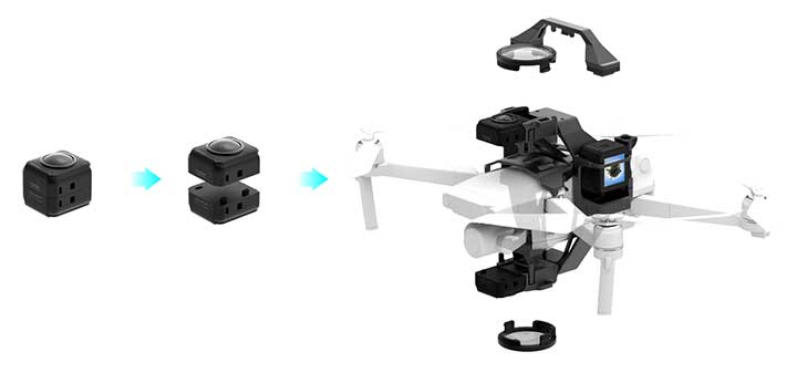
Insta360 ONE R is an interchangeable-lens action camera designed with three swappable Lens Mods for capturing different kinds of content. It has a Dual-Lens 360 Mod and a 1-Inch Wide Angle Mod co-engineered with Leica Camera AG. Advanced stabilization with Insta360’s FlowState algorithm achieves gimbal-like stabilization when shooting 360 degrees or with a standard wide angle lens. The 5.3K wide-angle lens can be swapped for a dual-lens setup that captures action in all directions at once. It captures brilliant 5.3K video and 19-megapixel photos even in complex lighting conditions. The ONE R is waterproof to 5 meters.
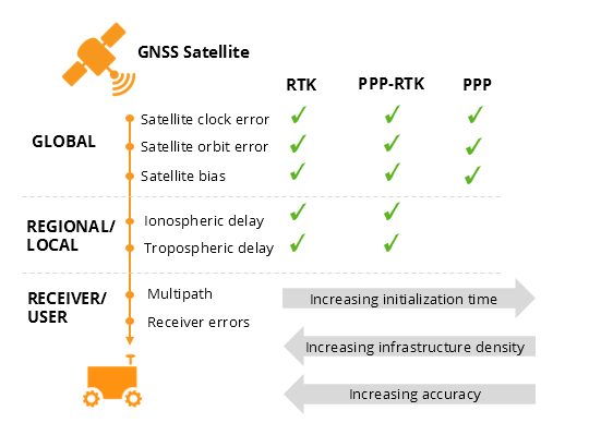
This insight column from Septentrio explains the role of GNSS corrections in precise positioning. It explores the three most popular correction methods: RTK, PPP and PPP-RTK.
Let’s say you need reliable accurate global positioning in your technology. You do some research and decide to get yourself a multi-frequency GPS/GNSS receiver. You order an evaluation kit, but how to get your receiver to deliver the high accuracy that it promises?
GNSS receivers rely on external corrections to compensate for GNSS errors to achieve decimeter- or centimeter-level accuracy as fast as possible.
Correcting GNSS errors
GNSS-based positioning is calculated using a method that, by itself, is limited in accuracy due to several errors caused by GNSS satellites as well as the Earth’s atmosphere.
Even the advanced clocks on board GNSS satellites experience minute drifts that cause clock errors.
The movement of GNSS satellites is predicted as they orbit the Earth. These predictions are not perfect, which results in orbit errors.
Satellite equipment introduces small signal errors, which are modeled as satellite biases.
Atmospheric errors caused by distortions and delays are experienced by the signal as it passes through the Earth’s ionosphere (outer layer) and troposphere (layer near the Earth’s surface).
The local environment around the receiver as well as the receiver itself can introduce errors. For example, satellite signals can be reflected off buildings and tall structures (multipath).
A GNSS receiver cannot correct satellite and atmospheric errors by itself; it relies on data provided by an external source. Clock and orbit errors are satellite-dependent, and so are the same around the world. Atmospheric errors, on the other hand, depend on the path the signal takes as it travels from the satellites to the user, differing depending on the receiver’s location.
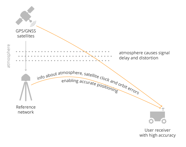
To overcome both satellite and atmospheric errors, a reference station (also known as a base station) can be used. A reference station — a GNSS receiver installed at a fixed and precisely known location — estimates GNSS errors and sends them in the form of GNSS corrections to the user receiver. A reference network consists of interconnected reference receivers spread over a geographic area.
A user receiver gets data sent from a GNSS reference station to correct satellite and atmospheric errors. (Image: Septentrio)
Receiver-side errors can only be handled partially, by robust receiver technology and careful operation. Depending on which type of corrections are applied, it can take a few seconds to several minutes of initialization time for high accuracy to be achieved.
Types of corrections for high-accuracy positioning
Until recent years, RTK and PPP have been the established methods of providing GNSS corrections to user receivers. But the demand for high-accuracy positioning is on the rise, paving the way for new positioning techniques such as the hybrid PPP-RTK.
RTK: Highest level of accuracy. With the RTK (real-time kinematic) method, a user receiver gets correction data from a single base station or a local reference network. It then uses this data to eliminate most of the GNSS errors.
RTK is based on the principle that the base station and the user receiver are located close together (a maximum 40 kilometers or 25 miles apart) and therefore “see” the same errors. For example, since the ionospheric delays are similar for both the user and the reference station, they can be cancelled out of the solution, allowing higher accuracy.
While in the RTK method corrections are provided for a specific location, in the PPP and PPP-RTK methods, a correction model is broadcast to a larger area, but with slightly lower accuracy. To transmit this correction model, a message format called SSR (Space State Representation) can be used. There is some confusion in the industry about the term “SSR” since it is often associated with the newer PPP-RTK method. But be careful, since “SSR” is occasionally used as a buzzword to refer to traditional PPP services as well.
PPP: Globally accessible and accurate, but at a cost. Precise point positioning (PPP) corrections contain only the satellite clock and orbit errors. Since these errors are satellite specific, and thus independent of the user’s location, only a limited number of reference stations is needed around the world. Because atmospheric errors are not included in PPP corrections, only a lower accuracy level can be achieved with this method. Also, a longer initialization time is expected of up to 20-30 minutes, which may not be practical for some applications. PPP has been traditionally used in the maritime industry; today it has expanded to various land applications such as agriculture as a convenient way to get global GNSS corrections.
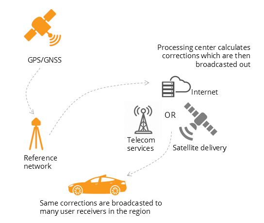
PPP-RTK: Best of both worlds? PPP-RTK (a.k.a. SSR) is the latest generation of GNSS correction services, combining near-RTK accuracy and quick initialization times with the broadcast nature of PPP. A reference network, with stations about every 150 kilometers (100 miles), collects GNSS data and calculates both satellite and atmospheric correction models.
As explained above, atmospheric corrections are regional, and so a denser reference network is needed than for PPP. These corrections are then broadcast to subscribers in the area via internet, satellite or telecom services. Subscribed receivers use the broadcast correction model to deduce their location-specific corrections, resulting in sub-decimeter accuracy.
Comparing the three GNSS correction methods
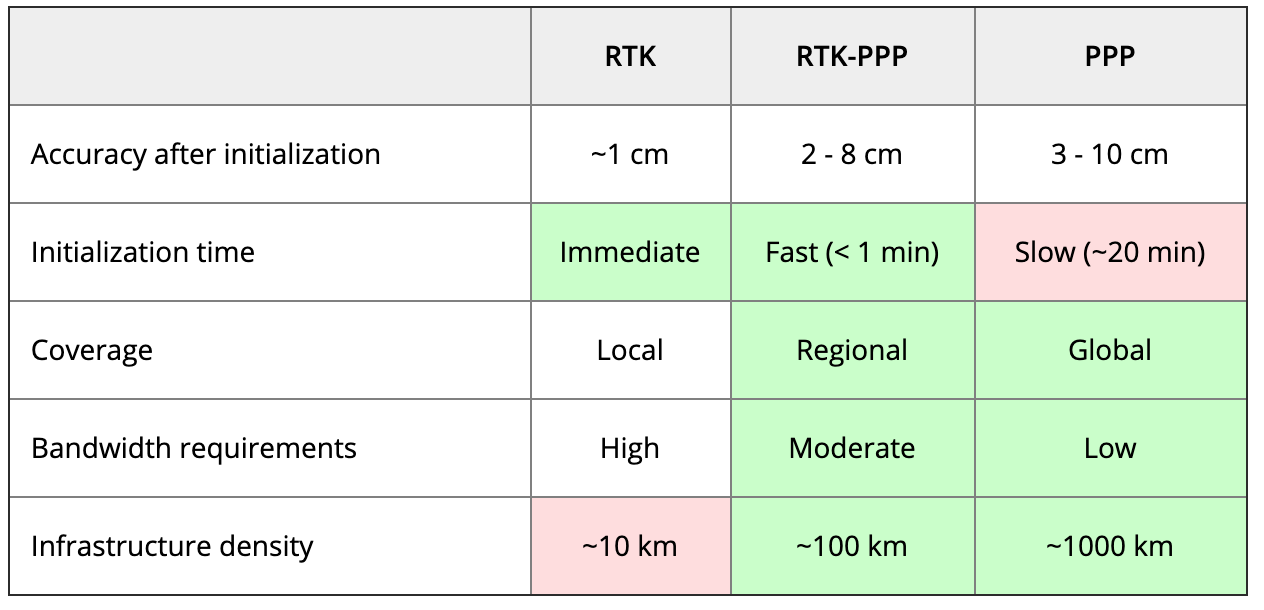
The table below compares the three correction methods, highlighting their strengths and weaknesses.
Table: Septentrio
The infrastructure density and initialization time for all three methods vary with the different kinds of errors that are corrected. The broadcast nature of PPP-RTK and PPP, as well as the lighter infrastructure that they require, makes these methods scalable for mass-market applications.
Types of errors that are corrected by each of the three methods. (Image: Septentrio)
Some GNSS receivers also incorporate advanced positioning algorithms to compensate for receiver-side issues such as multipath (for example, see Septentrio APME+), jamming and spoofing. This adds reliability and robustness to high-accuracy positioning.
Getting GNSS corrections
Modern industrial receivers often get their GNSS corrections via a subscription service, delivered via internet (using NTRIP protocol), satellite or 4G/5G. Today, there is a boom in the correction-service market driven by high-accuracy demands of the automotive industry, automation and smart consumer devices. Automotive suppliers and many other new players are deploying infrastructure to set up services for centimeter-level positioning around the globe.
User receivers often get their GNSS corrections via a subscription service delivered via internet, satellite or 4G/5G. (Image: Septentrio)
PPP and PPP-RTK corrections can even be transmitted directly by the GNSS satellites, as in the Japanese CLAS service from the QZSS constellation, or in the planned High-Accuracy Service (HAS) from Galileo. Depending on the network density and quality of the error modeling, different initialization times and accuracies can be achieved. This means that positioning quality can vary from one service provider to another.
Major telecom companies such as Deutsche Telekom as well as the Japanese Softbank and NTT are equipping their infrastructure with GNSS receivers to enable new corrections services. 3GPP, which provides specifications for mobile telephony including LTE, 4G and 5G, now covers broadcasting of GNSS satellite corrections in its mobile protocol. Since reference receivers are becoming part of critical infrastructure, such as telecom towers, it is essential that they have a high level of security to protect them from potential jamming or spoofing attacks (for example, Septentrio AIM+ technology).
Which corrections are right for me?
The right correction service for your technology will depend on your location and service area, your accuracy and reliability needs, as well as your budget. Because the corrections market keeps expanding, it is now more important than ever that integrators or GNSS manufacturers assist you in selecting the best correction method for your industrial application.
If you choose a GNSS receiver which does not “lock” you to a certain correction service, you will be free to choose a correction method which is most suitable for your application and its location. Such “non-locking” open-interface receivers also offer customers flexibility to switch to another more beneficial service in the future, as correction methods keep evolving.
Small businesses, including many surveyors, are being hit particularly hard by the current economic situation caused by the measures required to fight the COVID-19 pandemic because most of them do not have large cash reserves.
The CARES Act, signed into law on March 27, contains $349 billion to keep small businesses afloat. The funds are administered by the Small Business Administration (SBA) through participating banks.
Hundreds of thousands of borrowers have been approved for, or received, aid under the so-called Paycheck Protection Program, meant to give small businesses loans that would be forgiven if they were used to pay employees, rent, or mortgage principal. The program is one of four that the SBA is administering as part of the CARES Act.
The other three are the Economic Injury Disaster Loan (EIDL) loan advance, which will provide up to $10,000 of economic relief to businesses that are currently experiencing temporary difficulties; the SBA Express Bridge Loans, which enables small businesses who currently have a business relationship with an SBA Express Lender to access up to $25,000 quickly; and the SBA Debt Relief, which provides a financial reprieve to small businesses during the pandemic.
These programs — an unprecedented challenge for the SBA, which is already struggling with a surge in coronavirus-related loan applications through other programs such as its disaster loan program — were marred by technical and logistical glitches from the start.
On April 16, while many small-business owners were desperately trying to apply for loans, the SBA ran out of the relief money. Its website’s COVID-19 page announced: “SBA is unable to accept new applications at this time for the Paycheck Protection Program or the Economic Injury Disaster Loan (EIDL)-COVID-19 related assistance program (including EIDL Advances) based on available appropriations funding. EIDL applicants who have already submitted their applications will continue to be processed on a first-come, first-served basis.”
As of press time, Congress and the White House are negotiating the possible release of additional rescue funds.
New series of free webinars for construction, geopositioning and agriculture facilitate learning
Topcon Positioning Group is launching a free webinar program for the construction, geopositioning and agricultural sectors, exploring key topics affecting the industry and providing the latest updates and project management solutions.
The Topcon Talks series, consisting of numerous informative webinars, has been created in response to the ongoing COVID-19 pandemic and aims to provide those working from home with valuable educational resources, while maintaining steady communication with Topcon customers, dealers and the wider industry.
The webinars will focus on a range of topics such as improving productivity using digital construction workflows, overcoming barriers to technology adoption, and more practical how-to sessions for customers and dealers on specific Topcon solutions.
The webinars will be delivered by a range of Topcon experts, with input from several other industry specialists, and cover a multitude of topics including:
Always One Step Ahead – an overview of Topcon’s latest product developments, market focuses and acquisitions
State of the Industry series – looking at the barriers to technology adoption in construction, such as attracting talent and bridging the skills gap
Detailed technical sessions showcasing latest hardware, software and web services to get the most out of Topcon solutions
The content series is live on the site, with new sessions taking place regularly over the coming weeks. All sessions are free to attend, and those wanting to participate will first need to register on the Topcon website.
“Everyday life has changed very quickly, and businesses across the world are having to adapt. At Topcon, we are working tirelessly to help the industry weather this storm. We’re aware that at this time, the majority of people are working from home, and we want to continue to support our customers and colleagues as much as possible,” said Ron Oberlander, vice president of global professional services at Topcon Positioning Group. “That’s why we’ve developed this webinar series — to provide an opportunity for continued professional development so that professionals can remain as productive as possible during this challenging time and be in the best position possible to accelerate the industry’s recovery when we come out the other side.”
The webinars are also recorded and uploaded to the site once complete, so those who are unable to attend the session can access the content in their own time.
My February 2020 column provided an analysis of the differences between the latest published hybrid Geoid18 values provided on NGS’ Datasheet and the computed geoid height value using the published NAD 83 (2011) ellipsoid height and NAVD 88 orthometric height. The column highlighted issues on differences due to published heights that have changed since the database pull for Geoid18. It mentioned that future columns will address differences in other portions of CONUS. This column will focus on differences between published Geoid18 values and Geoid12B values in Southern Louisiana. Why are users seeing large differences between the two models?
My last column mentioned that the technical report on Geoid18 provided a good explanation on the stations used in the United States Gulf Coast region. See box titled “GPS on Bench Marks for GEOID18 in the Gulf Coast Region.”
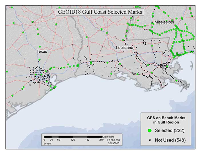
GPS on Bench Marks for GEOID18 in the Gulf Coast Region
Figure 1: GEOID18 Gulf Coast selected marks: There are areas of complex vertical crustal motion in the Texas/Louisiana Gulf Coast region of the United States which render many control station elevations in the region invalid. The selection of GPS on Bench Marks in this region was limited to the small number of marks where the leveling and GPS data agreed to minimize the influence of crustal motion in the hybrid geoid model. Figure 1 depicts the selection of stations used in the hybrid geoid model along the Texas/Louisiana Gulf Coast. (Image: National Geodetic Survey)
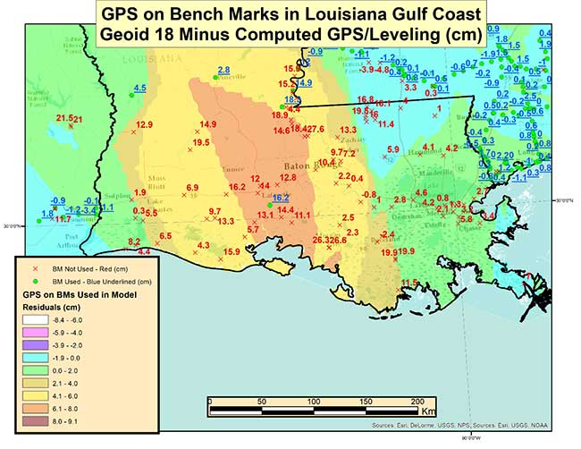
As highlighted in the last column, very few stations in Southern Louisiana were used in the creation of the Geoid18 hybrid geoid model. As provided in my last column the box titled “Differences on GPS on Bench Marks in the Gulf Coast Region” depicts the differences between the published Geoid18 value and the computed geoid value using the latest NAD 83 (2011) ellipsoid and NAVD 88 orthometric height.
Differences on GPS on Bench Marks in the Gulf Coast Region
Image: National Geodetic Survey
The plot indicates that there are many large differences. Many of these differences are to be expected because the Southern Louisiana is an area of known crustal movement. NGS recognizes this and includes the statement below on datasheets for stations published in Southern Louisiana (see box titled “Statement on NGS Datasheet for Stations in Southern Louisiana”).
Statement on NGS Datasheet for Stations in Southern Louisiana
This station is in an area of known vertical motion. Due to the variability of land subsidence, uplift, and crustal motion, NGS has, determined the orthometric heights for marks in these suspect subsidence areas should be considered valid only at the epoch date associated with the orthometric height. These heights must always be validated when used as control. All previously superseded orthometric heights are now considered suspect and are available in the superseded section. NGS does not recommend using suspect or superseded heights as control.
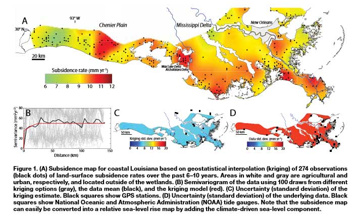
Looking at the figure indicates that there is a significant variation of subsidence occurring in coastal Louisiana. The legend indicates that the subsidence rates range between 0.6 to 1.2 cm/year.
Figure 1 from A New Subsidence Map for Coastal Louisiana
The box titled “Excerpt from Anthropogenic and Geologic Influences on Subsidence in the Vicinity of New Orleans, Louisiana” depicts estimates of crustal movement between 2009 and 2012 in the vicinity of New Orleans. Several of the areas in the plot indicate subsidence rates exceeding -1 cm/year. Once again, the figure shows the local variability of subsidence rates.
Excerpt from Anthropogenic and Geologic Influences on Subsidence in the Vicinity of New Orleans, Louisiana
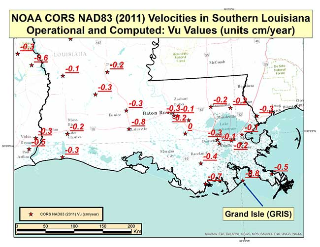
Last year, NGS performed the Multi-Year CORS Solution 2 (MYCS2). This was described in previous columns, which can be viewed here and here. The MYCS2 process generated computed and modeled velocities for CORSs. The box titled “CORS NAD83 (2011) Vu Velocities” is a plot that depicts the velocities in the “upward” component in cm/year for NOAA CORS that are operational and have a computed velocity in Southern Louisiana. So, what does this mean to estimating a hybrid geoid model in Southern Louisiana?
CORS NAD83 (2011) Vu Velocities
Image: National Geodetic Survey
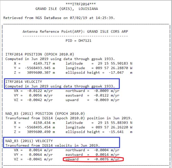
The plot indicates that the rates vary from -0.1 cm to -0.8 cm. It should be noted that these stations are CORS and they are typically installed on structures that may not capture the entire amount of subsidence at the land surface. The box titled “CORS Position and Velocity for Station GRIS” provides an example of a CORS sheet from NGS CORS website.
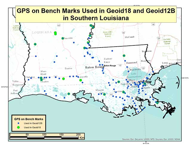
Now, let’s look at differences between Geoid12B and Geoid18 in Southern Louisiana. The box titled “GPS on Bench Marks Used in Geoid18 and Geoid12B” depicts the stations used in Geoid12 and those used in Geoid 18. As indicated in the plots, there were a lot more stations used in the generation of the Geoid12B model than those used to create the Geoid18 model.
GPS on Bench Marks Used in Geoid18 and Geoid12B
Photo: National Geodetic Survey
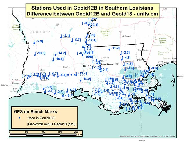
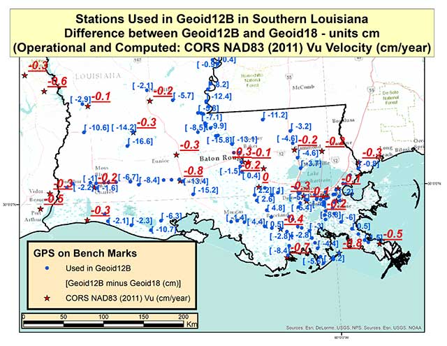
The box titled “Differences between Geoid12B and Geoid18 in Southern Louisiana” provides the values of Geoid12B minus Geoid18 in centimeters on the GPS in Bench Mark stations used in Geoid12B.
Differences between Geoid12B and Geoid18 in Southern Louisiana
Photo: National Geodetic Survey
As indicated in the plot, there are some large differences between Geoid12B and Geoid18 values; a few differences exceed 15 centimeters. Based on the previous discussion of crustal movement in Southern Louisiana, this probably shouldn’t come as a surprise. The box titled “Differences between Geoid12B and Geoid18 with Vu Velocity Values” depicts the differences in the hybrid geoid models and the NAD83 (2011) CORS Vu rate.
Differences between Geoid12B and Geoid18 with Vu Velocity Values
Photo: National Geodetic Survey
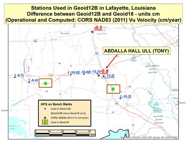
The box titled “Differences between Geoid12B and Geoid18 in Lafayette, Louisiana” depicts the differences in the two hybrid geoid models and the NAD83 (2011) CORS Vu rate values in the Lafayette, Louisiana, region. This region has some of the largest differences between Geoid12B and Geoid18 values in Southern Louisiana. As indicated in the plot, CORS station TONY has a Vu rate of -0.8 cm/year which is fairly large, and the differences between Geoid12B and Geoid18 values are fairly large at the -10 to -15 cm level. Once again, users should expect differences between the two hybrid geoid models because there has been movement in the area and because different GPS on Bench Mark stations were used in the generation of the hybrid geoid models. In the Lafayette region the two stations used in the generation of Geoid18 were not used in Geoid12B (see stations highlighted in a box).
Differences between Geoid12B and Geoid18 in Lafayette, Louisiana
Photo: National Geodetic Survey
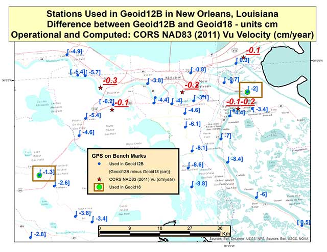
The box titled “Differences between Geoid12B and Geoid18 in New Orleans, Louisiana” depicts the differences in the hybrid geoid models and the NAD83 (2011) CORS Vu rate values in the New Orleans, Louisiana, region. Two of the same stations that were used in the development of Geoid12B and Geoid18 are highlighted with a box. The difference between the two geoid model values are much less in this region compared with the Lafayette region. The CORS Vu velocities are also less than the CORS station (TONY) value in Lafayette. Saying that, the differences on stations not used in Geoid18 have differences ranging from -4 to -8 cm going southward toward the Gulf of Mexico. Once again, Southern Louisiana is subsiding so these differences are not surprising.
Differences between Geoid12B and Geoid18 in New Orleans, Louisiana
Photo: National Geodetic Survey
This means if someone uses NGS’ OPUS web tool to compute a GNSS-derived orthometric height, the NAVD 88 GNSS-derived orthometric height could be significantly different than the published stations in this region. Some of the difference could be due to the difference between the Geoid12B and Geoid18 published values, and some could be due to crustal movement in Southern Louisiana. Saying that, I mentioned in my last column that NGS performed a large GNSS network project in Southern Louisiana in 2016. The GNSS-derived ellipsoid heights were loaded in NGS’ database in March 2019, but the GNSS-derived orthometric height from the 2016 project are not yet finalized so they have not been loaded into NGS’ database. Once finalized and loaded into the database, the 2016 GNSS-derived orthometric heights should be more consistent with GNSS-derived orthometric heights estimated using the NGS’ OPUS web tool. This column focused on differences between published Geoid18 values and Geoid12B values in Southern Louisiana. It provided reasons why users may see large differences between the two models.
Technology continues to develop and put more capability, data storage and ease of use into many professional’s hands, and surveyors are no different in their needs.
Spatial data collection has become an important task in the diverse service world of today’s surveyor with a variety of platforms, sensors and techniques being used to provide this operation.
The movement toward completing a “digital twin” of existing improvements and facilities worldwide has opened the door for new means and methods for data collection. Surveyors are taking a front-line role in producing the spatial data necessary for much of the internal and external infrastructure being used in today’s cutting-edge digital modeling.
Necessary accuracy and precision
However, not all data-collection systems offer the accuracy and precision deemed necessary by today’s surveying profession. These systems also need to be tough enough to handle the environmental conditions surveyors face in their everyday work, yet be user-friendly enough to make the data-collection process efficient.
Surveyors require a system designed for rugged use, yet built with a high-visibility screen, easy-to-use interface and reasonable battery life to allow effective and confident data collection. Many data collectors tout these features, but many of them fail when subjected to the harsh conditions of surveying and construction sites.
Times, however, are a changing and a new tablet is raising eyebrows.
DT Research Inc., a Silicon Valley electronics provider, has provided mobile and medical computing devices to many professions for more than 20 years. They have taken one of their most popular models, the DT301, and added integrated significant upgrades that brings it squarely into the surveying and geospatial world.
This rugged tablet can now include a multi-frequency GNSS module and a second, 3D-capable, stereo-imaging camera for capturing photometric information.
High-capacity, hot-swappable battery pack with power-saving modes
IP65-rated for water and dust resistance
MIL-STD-810G for shock and vibration protection
MIL-STD-461F for EMI and EMC tolerance
Multi-frequency GNSS (including GPS, GLONASS, Galileo and BeiDou)
External GNSS antenna capable
Intel RealSense Depth camera, 2D barcode scanner
Long-range Bluetooth, 4G LTE, digital pen support
Sturdy external keyboard with various mounts for static installation
Rugged yet reasonable weight of 3.1 pounds
Multiple mounting options for precise measurement
Rugged, but not too heavy
The first impression a new user of the DT301X-TR will notice is that while it is heavier than the normal personal tablet, it is very rugged yet not noticeably heavy. The additional weight it does carry, however, gives the user a sense of durability and confidence to take it into fouler environments without fear of infiltration or hazardous climate concerns.
The external bumpers can take significant abuse, and the rubber rear guard is used for gripping the tablet effectively during data collection tasks. Several mounts are available for this unit, including a pole mount in conjunction with the external GNSS antenna for higher accuracy location determination.
This unit runs the Microsoft Windows 10 IoT (internet of things) Enterprise operating system, so most users will already have a general feel for the overall interface. All the normal Windows tools are there (email, browser, etc.), so little training is needed for beginners.
Connectivity is available through dual-band Wi-Fi and/or 4G LTE communications as well as long-range Bluetooth connections where needed. The unit runs on an Intel 8th-generation core processor and SSD storage for fast computing and data access needs.
In addition to computing performance, this model also exceeds expectations with its robust screen. Where most high-def screens on phones and tablets suffer in daylight conditions, the DT301X-TR allows the user to maintain great visibility and keep working with visual confidence.
GNSS module and antenna
The DT301X-TR can be loaded with several data-collection software packages, depending on your application. For traditional surveying, Microsurvey’s Field Genius is used for locating survey points with the GNSS module. Several programs for data collection are available, depending on the accuracy required by the user.
Photo: DT Research
A helical mobile dual-frequency GNSS antenna is mounted directly on the tablet for receiving survey-grade positions with an RTK correction service. The tablet can also be used with an external GNSS antenna mounted on an extendable pole for a more conventional surveyor-style method of data collection while providing stability for the user.
The data-collection process for mapping is intuitive and allows for uploading existing shapefiles for reference to existing conditions. Exporting information after the data-collection task can be completed in two different formats: shapefiles and KML files.
Photo: DT Research
For the higher accuracies typically required for surveyors, the unit utilizes the pole mount to ensure the accuracy level is not compromised by human interaction, and it connects to an external GNSS antenna. The software allows the user to collect more precise locations through several means: static, real-time kinematic from the user’s base station, or through a real-time network solution from an external source.
The data collection process in Field Genius is very user friendly and allows for customized point naming and automatic linework between points. Field Genius also contains standard COGO tools and routines that allow the user to perform field calculations right on the job, saving valuable time and money for the practitioner and the client.
Exporting of field data is robust and allows for creation of DXF/DWG files of linework and LandXML files for surface and point downloads. The user can also export raw data in a GNSS Survey format or the industry standard “field book” format as well. Importing background files is just as simple, so the user can have additional information at their fingertips for reference during their data collection process.
Also, the DT301X-TR can be utilized for construction staking with an extensive array of staking reports available for user verification. Proposed TIN surface models can be imported for site and roadway staking for placing cut/fill points on the fly.
Cameras make it shine
The DT301X-TR, however, is not just a fancy conventional surveying data collector; the Intel RealSense Depth camera and DOT3D Pro software from DOT Product is the latest development to be added to the rugged tablet that makes this platform shine. This latest technology from Intel allows the user to photograph and video spaces that even the newest laser and lidar scanning equipment can’t access.
Stereo depth modeling is enhancing the data-collection process for surveyors as a new tool to collect important information for engineers, architects and contractors. By collecting close quarters information in real time, a more complete BIM and/or “digital twin” data set can be accomplished faster and more cost efficiently than ever.
This version of remote sensing is becoming very popular with other vehicles and platforms (such as UAVs), yet being integrated into a single unit with GNSS capability is key to making the DT301X-TR a game changer.
The divide between the macro (GIS mapping) and micro (traditional surveying) of spatial data collection is closing, but it will take some time before satisfying the surveying community. The DT301X-TR is closing that gap by marrying the accuracy of GNSS measurement with the precision of 3D analyzation technology.
DT Research began by creating a bulletproof tablet made for durability and dependability, but has raised the bar with a state-of-the-art satellite measurement module and remote-sensing capability through the RealSense camera system.
Wrapping all this technology into a rugged unit running on an industry-standard software platform, DT Research has provided an insight to what the future of data collection looks like, no matter what profession one is in.
What are the key obstacles to widespread adoption of 3D positioning and guidance in the construction industry?
Ismael Colomina, GeoNumerics
“Construction site monitoring with UAVs requires regulated standard scenarios that allow flying over people and in urban areas without spending weeks obtaining the needed permissions. It also requires the development of critical UAV components, especially the guidance, navigation and control (GNC) systems. Safe UAV navigation — guaranteeing positional accuracy with small probabilities of actual errors larger than the specified ones — is still under development and will involve a multi-sensor navigation system. Current GNSS augmentation systems, such as WAAS and EGNOS, may not be appropriate for flights in the very-low-level (VLL) airspace.” Ismael Colomina, GeoNumerics
Members of the EAB
Tony Agresta Nearmap
Miguel Amor Hexagon Positioning Intelligence
Thibault Bonnevie SBG Systems
Alison Brown NAVSYS Corporation
Ismael Colomina GeoNumerics
Clem Driscoll C.J. Driscoll & Associates
John Fischer Orolia
Ellen Hall Spirent Federal Systems
Jules McNeff Overlook Systems Technologies, Inc.
Terry Moore University of Nottingham
Bradford W. Parkinson Stanford Center for Position, Navigation and Time
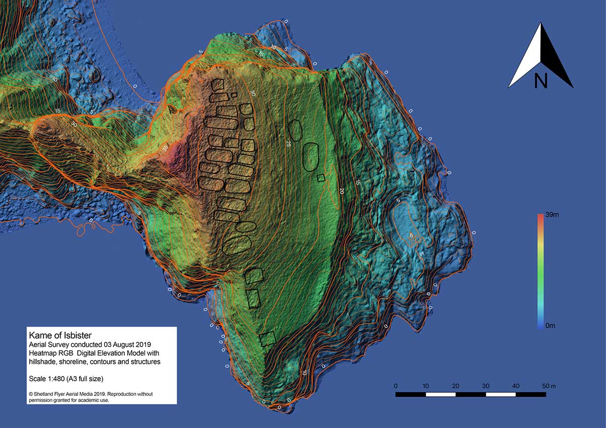
The mysterious and fascinating Kame of Isbister is situated in Shetland’s north mainland near the North Roe. The location has been studied several times, including by the Extreme Archaeology TV series in 2003. The uninhabited grassland continues to attract explorers because of a series of secret structures.
Those structures are hidden on the sea-faced slope and can’t be seen from the land nearby. One theory posits that it’s an eremitical monastery settlement. The late Pictish/early Medieval site is hard to access — and that’s where drones coupled with GNSS receivers helped explorers.
Because the site is hard to access, the team decided to use the DJI Phantom 4 RTK SUA (drone and base) with two flights. One flight captured both the Kame and a piece of the mainland for context, with a ground sample distance (GSD) of 2.4 centimeters/pixel (cm/px). The second flight was on a shorter GSD of 1.9 cm/px to capture detailed pictures of the cape and structures.
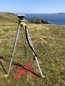
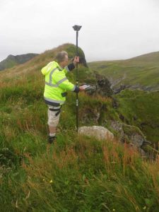
Before the survey, the team used the Emlid Reach RS+ real-time kinematic (RTK) receiver to identify and establish the base mark for the drone on the mainland nearby.
Photo: Emlid
The Reach RS+ collects ground control points. (Photo: Emlid)
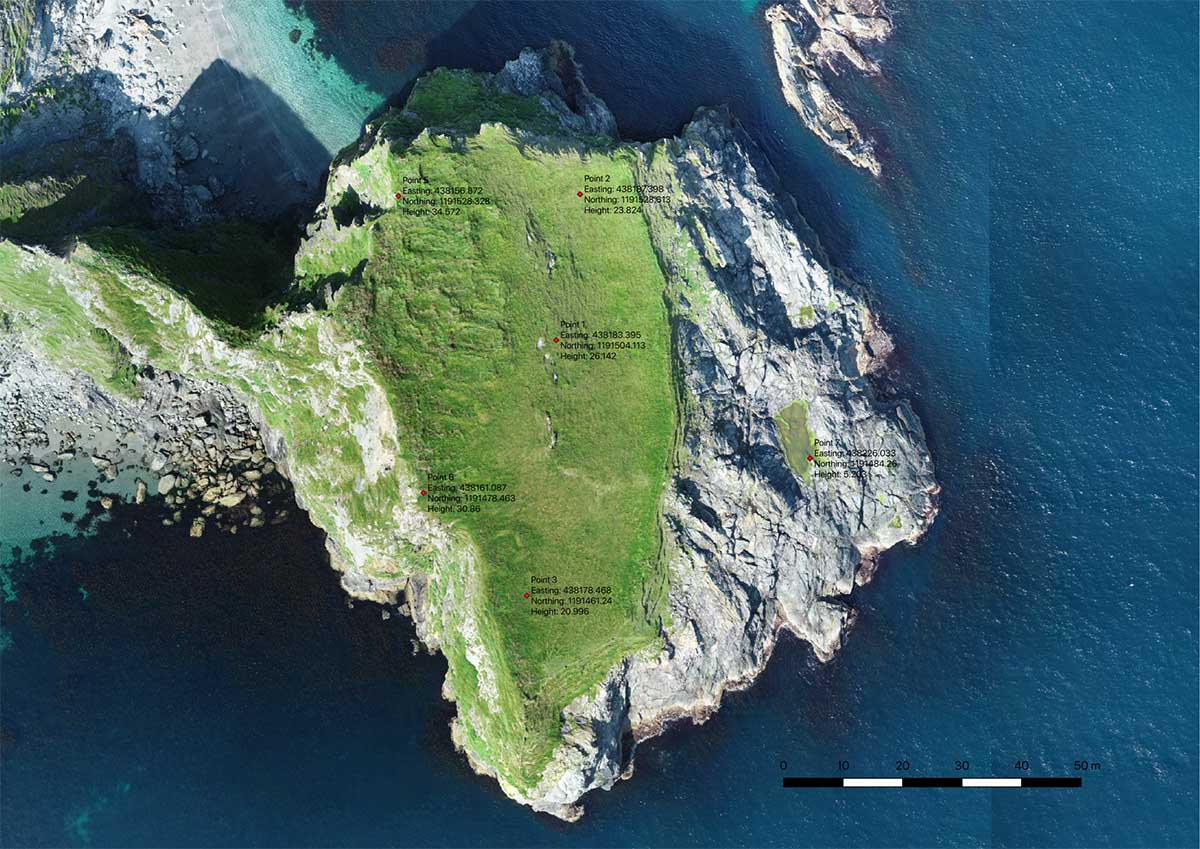
Ground control point locations. (Image: Emlid)
The base mark was then post-processed using data from the OS Net reference station in Lerwick. Considering the long baseline (52 kilometers), it took the team four hours to observe the mark with Reach RS+. Later, when the archaeologists managed to climb the headland, the RTK receiver collected several noticeable control points.
Creating the 3D model. During both flights, the drone’s base was sending corrections in RTK mode. In post-processing, horizontal accuracy of the processed map initially was within 10 cm with vertical at 15 cm. After adding the control points gathered with the RTK receiver, the error was reduced to 6.5 cm, significantly increasing the accuracy of the model.
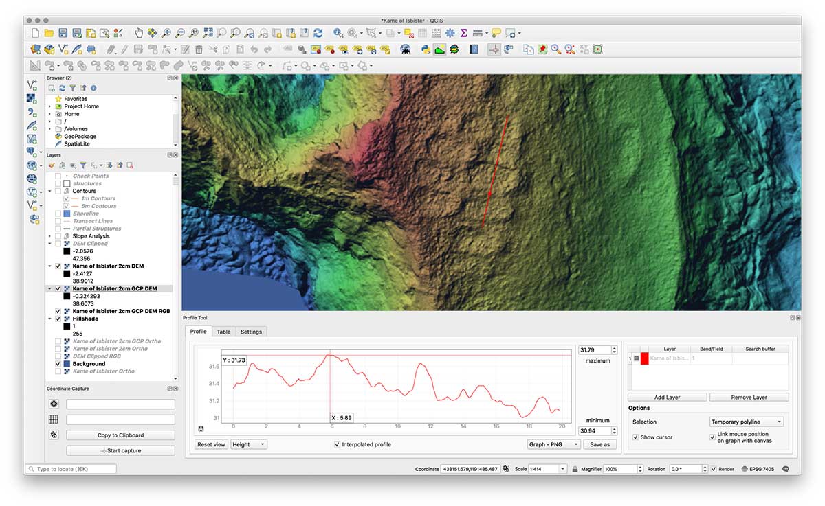
The team performed the GIS processing in QGIS 3.4 LTR.
Screenshot: Emlid
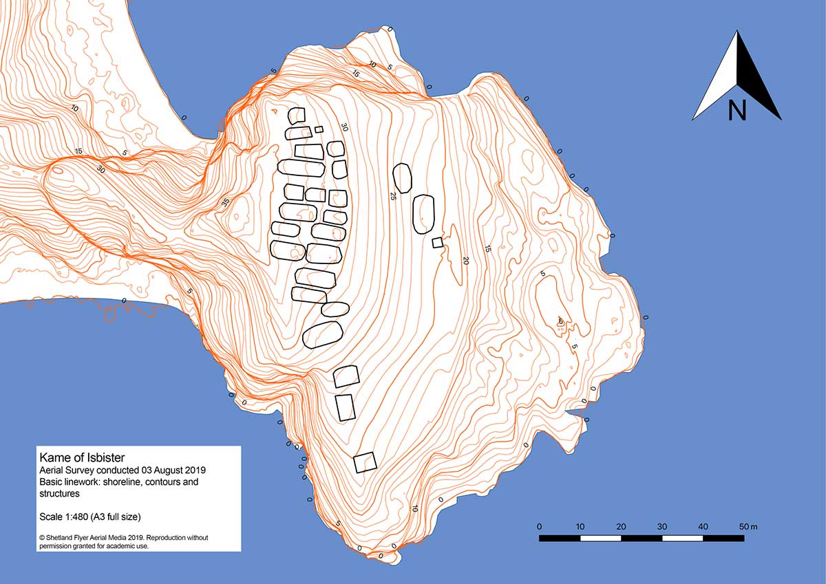
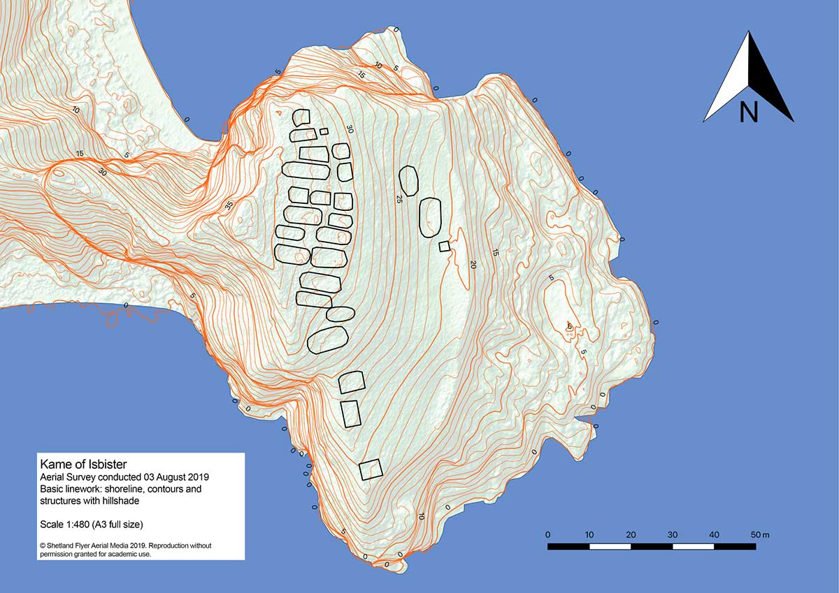
Despite the long grass, they managed to distinguish each structure out of the orthomosaic using the 32-bit floating point raster digital elevation model (DEM). The team created a basic map with structures and contours, a hillshade version and a heat map.
With proper preparation and setup, a GNSS RTK receiver with a drone can gather enough high-accuracy data to create accurate models and maps of an archaeological site — even if it’s hard to reach.
Shoreline contours and structures. (Image: Emlid)Shoreline contours and structures with hillshade. (Image: Emlid)3D model: The heatmap of the Kame of Isbister shows elevations and the archaeological site. (Image: Emlid)
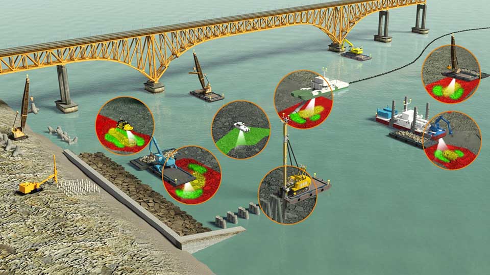
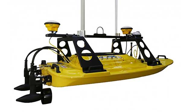
Teledyne Marine has released the Z-Boat 1800-T unmanned survey vessel, equipped with Trimble’s high-precision GNSS heading receiver and compatible with Trimble Marine Construction (TMC) software.
The Z-Boat 1800-T enables marine construction and dredging projects to run efficiently and be monitored in real time anywhere in the world.
The Z-Boat 1800-T, designed and manufactured by Teledyne Oceanscience, is a high-resolution shallow water hydrographic unmanned survey vehicle with the newly released Odom Hydrographic Echotrac E20 Singlebeam Echosounder and dual antenna Trimble BX992 GNSS heading receiver. Each sensor is integrated into a compact, portable and cost-effective package.
The combination of Trimble’s high-precision heading and positioning/guidance paired with Teledyne’s accurate/precise sonars allow for data collection under harsh conditions. Both sensors can be removed and mounted on other watercraft and barges to maximize data-collection capabilities.
The data is remotely viewable in real time, giving the operator full control and confidence. The boat’s small footprint allows access to areas that are too small, confined or unsafe for larger vessels.
Photo: Teledyne Marine
“Teledyne Marine and Trimble continue to create a paradigm shift for marine construction by providing real-time vision, guidance and survey across a project’s complete construction lifecycle — improving safety, eliminating or reducing work redoes, and helping to complete projects faster and under budget. This system provides as-building updates or what we call ‘eyes below the water,’” said Ted Germann, Teledyne Marine’s vice president of Emerging Markets.
“Trimble’s experience in GNSS guidance systems, and Teledyne’s leadership in shallow-water hydrographic surveying provides an ideal solution for marine construction contractors and surveyors,” said Kevin Garcia, general manager of Trimble Civil Specialty Solutions. “The Teledyne Z-Boat 1800T release means that near-shore construction workflows now have a quick mobilization tool to identify sub-surface obstructions, provide ad hoc inspections and increase site safety. This feature-loaded solution makes the unmanned surveying vessel affordable for all sizes of customers.”
Klau Geomatics has released processing that brings precise point positioning (PPP) and post processed kinematic (PPK) together in an optimized solution.
The autonomous solution can work anywhere without any other user inputs, such as base station data and radio/GSM links, the company added.
According to Klau Geomatics, the solution works on its own to achieve high accuracy, regardless of the location of the user. Accurate datum and tectonic plate motion corrections, specific to different countries and regions, are automatically applied to deliver the most accurate solutions.
In addition, Klau Geomatics’ NRT technology gives users — specifically those in the drone inspection industry — the ability to attain absolute accuracy to analyze change over time on 3D assets, the company said. The precise corrections are applied to data from custom-tuned KlauPPK GNSS receivers in the KlauPPK post processing software to enable centimeter-level accuracy anywhere in the world without the need for RTK, CORS or local base station data.
Finally, Klau Geomatics’ hybrid terrestrial multi station and PPP algorithm are offering even more refined accuracy in areas such as the U.S., Europe, Japan, New Zealand and Australia. Data from as many as 15 reliable long-range CORS stations, where available, are applied to the processing. The enhanced PPP solution achieves 1-3cm XYZ absolute accuracy in many parts of the world.
The same KlauPPK software workflow applies, to synchronise camera events, apply lever arm corrections, manage coordinate systems and geoids, apply site localizations, capture ground points and more. Instead of choosing a base station, which should be within 20 miles of the site, or setting up an RTK radio link, users with an active KlauPPK subscription can process a high accuracy trajectory, anywhere, without any other inputs, Klau Geomatics said.
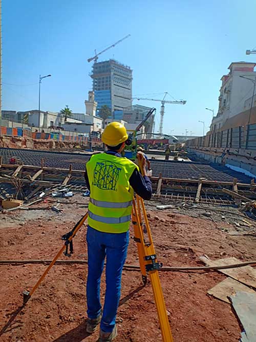
Engineers are monitoring in real time the effects on Casablanca’s aging buildings during tunnel construction using a Spectra Precision GNSS receiver.
Vibrations during the construction of a new 1,890-meter tunnel adjacent to Casablanca’s Old Medina, the 250-year-old section of the famed Moroccan city, challenged the stability of its historically important buildings.
To monitor in real time the effects on the Medina’s aging buildings and to confirm that the construction work meets all engineering standards and guidelines, ETAFAT, a geospatial information acquisition and processing company, used the Nikon XF Total Station to perform more than 100 daily inspections. The ETAFAT team relied on optical targets placed on building facades whose coordinates were determined by forced centering to complete the inspections.
The new Les Almohades tunnel, beneath the Boulevard des Almohades, runs parallel and adjacent to the old Medina. Together with its 380 meters of access roads, the twin-tube tunnel, which carries traffic in two unidirectional lanes in each tube, was constructed to reduce traffic congestion.
According to ETAFAT engineers, the Nikon XF 1” with its fast autofocus function, saved considerable field time. The Nikon XF enabled fast collection of highly accurate observations throughout the monitoring and control of the planimetric and altimetric locations of the structure. The monitoring of the buildings during the various phases of the tunnel’s construction generated a large amount of data essential for understanding the consequences of the work and defining any necessary corrective measures.
The Nikon FX 1,” with its advanced options and Survey Pro software, enabled survey teams to quickly yet accurately perform a variety of other essential field tasks.
These tasks include digital terrain modeling (DTM), cubature calculations, coordinate geometry (COGO) topometric calculations and layout control with customized report generation. The use of Survey Pro software enabled ETAFAT engineers to fully integrate their total station work with their fleet of Spectra Geospatial SP60 GNSS receivers.
The Nikon XF 1” is a mechanical total station that stands up to tough worksite conditions. It is designed to quickly capture accurate measurements, and it offers crisp, clear optics for sighting in both bright and low-light conditions.
Its dual-color touchscreen displays run Survey Pro, Survey Basic and Layout Pro.
It is also equipped to take advantage of the optional Trimble Protected L2P device for asset security to locate lost, stolen or missing equipment. Its hot-swappable batteries reduce downtime and a PIN enhances security in the field.