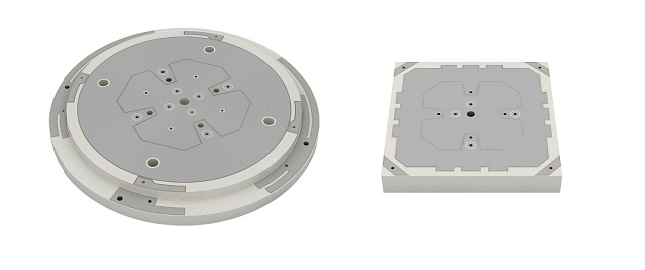
SABIC, a global leader in the chemical industry, has introduced two new LNP Thermocomp compounds that offer the potential to improve signal gain performance compared to ceramics in second-generation automotive GNSS antennas.
The new compounds, LNP Thermocomp ZKC0CXXD and LNP Thermocomp ZKC0DXXD, help enable the design and molding of antenna substrates with more complex pattern markings that add effective surface area, a critical factor in enhancing signal capture.
For customers that use ceramics, switching to the LNP Thermocomp compounds can help lower system costs by avoiding secondary operations, as well as improving antenna performance. Designers and engineers who find current materials inadequate for developing novel, high-resolution GNSS antennas can help address new requirements with the SABIC products, the company said.
“As GNSS antenna technology advances to its second generation with higher resolution, SABIC continues to enhance the scope and capabilities of our LNP specialty compounds portfolio to meet new performance requirements,” said Joshua Chiaw, director of business management, LNP, SABIC. “Our new LNP Thermocomp compounds can help antenna manufacturers achieve superior signal gain compared to ceramic substrates. They also provide flexibility to produce smaller parts with the same performance as ceramic, or equal-size parts with better performance. This remarkable combination of improved signal capture and design freedom, plus system cost advantages, can help propel innovation in GNSS technology — a keystone of occupant safety today and autonomous driving in the future.”
The LNP Thermocomp compounds, which offer a high dielectric constant (Dk) for miniaturization and a low dissipation factor (Df) to facilitate signal acquisition, can be tailored to meet the electrical requirements of individual applications. They feature electroplating capability, good thermal resistance for reliability, and the design freedom and production efficiency of thermoplastics. Both are well-suited for shark fin-style and new conformal antenna designs.
Vodafone and Topcon Positioning Group are developing a European precise positioning system, Vodafone GNSS Corrections, that will locate Internet of Things (IoT) devices, machinery and vehicles with a greater degree of accuracy than using individual GNSS.
Vehicles, scooters and robotic lawn mowers can be securely monitored in real time to within a few centimeters when connected to Vodafone’s global IoT network.
Vodafone GNSS Corrections will use technology from Topcon, which corrects inaccuracies from navigation satellite signals. Location accuracy is improved from a few meters to centimeters using Topcon’s dense European network of thousands of GNSS reference stations, especially when vehicles and devices are fitted with suitable antennas and receiver equipment.
Vodafone will offer a singular module configuration that can extend across national borders.
Vodafone is inviting select customers to join pilot customer trials in Germany, Spain and the UK, which will begin this month. The companies aim to test the service using a wide variety of devices connected to Vodafone’s global IoT network — one of the largest with more than 150 million connections — and its pan-European network covering 12 countries.
Pinpoint accuracy is critical to the mass adoption of vehicle-to-anything (V2X) technology used for driverless vehicles, autonomous machinery and robots. For example, e-bike riders could use Vodafone GNSS Corrections to provide details of their exact location and then alert other road users of their presence.
Vodafone GNSS Corrections also supports Vodafone’s efforts to improve V2X location accuracy, especially when sharing trusted data to help prevent unnecessary accidents and fatalities on Europe’s roads. As such, Vodafone is offering precise positioning as a complement to Vodafone’s new Safer Transport for Europe Platform (STEP) which allows entities to communicate with each other where no line of sight exists. Unveiled in March 2022, STEP has been successfully tested in Germany and the UK and will be made available via Vodafone Automotive and third-party apps later this year.
Project GENIE (GNSS Excluded Navigation Intelligent Enhancement) will mature and advance non-GNSS solutions as part of a long-term objective to enable assured location and navigation in commercial aerospace, helping to unlock the benefits and value of autonomy in civil aviation. The support from NATEP will enable the consortium to take a significant step toward navigation in GNSS-spoofed or -denied environments, the companies said.
“Tomorrow, as we look towards single-pilot operation and future autonomous aircraft, there will not be a pilot or air traffic controller available to mitigate these risks,” stated the companies in a press release. “GENIE has been developed to step into this role. It will be able to identify when a GPS signal has been compromised and, using a combination of techniques, provide a location position as accurate as GPS.”
“The need to provide assured, resilient navigation is a critical enabler for autonomy in the aerospace environment,” said Charles Smith, CCO at Archangel Imaging. “GENIE is a core element of this, and we are very excited to be working with NATEP to help push this technology forward. We see significant commercial exploitation opportunities as a result of this project in the UAV and broader aviation markets and are thrilled to be a part of this round of NATEP funding and support.”
Advances in GNSS technology constantly expand the range of projects that benefit from them.
ComNav Technology
A telecom company adopted its CORS station to build China’s national CORS service for public companies. It is increasingly used for field robotics, including the development of self-driving cars.
Leica Geosystems
Bernhard Richter, vice president of Geomatics, Leica Geosystems AG, pointed to one of the biggest infrastructure projects in Europe, which aims to connect London to Birmingham, Manchester and Leeds with a high-speed railway system, avoiding the need to fly between those cities. This will have great environmental benefits because high-speed trains are much more efficient than planes.
However, high-speed rail requires tremendous precision. “First comes the prep work, moving dirt,” said Richter. “Then you must install the railroad ties with tenths of a millimeter precision relative to each other to avoid side accelerations. For a surveyor, it really has everything in one project. You need to constantly work with civil engineers. You then try to build as much as possible with machine-control-guided systems to make the leveling as automated as possible.” The project will include building bridges over whole valleys and monitoring them, particularly during the construction phase, to ensure that they are not moving.
“Even the factory they are building is huge, so just to build the factory you need a lot of surveying,” Richter said. The project is generating 25,000 jobs at 300 construction sites, all of which must be managed on very tight schedules. In this context, the quality of the survey gear is critical. “On a construction site, the surveyor should be an invisible person,” Richter said. “When they come with the big machines and want to get stuff done, they don’t want a surveyor on the site. So, he has to work off hours, then remain on alert and trust that what comes out of an instrument is correct.” Leica Geosystems is one of the main suppliers for this project. “They chose us because of our focus on reliability, trust and quality.”
Trimble
Software is increasingly driving sales, pointed out Boris Skopljak, vice president, Surveying & Mapping Strategy and Product Marketing at Trimble Inc. As an example, he cited Trimble’s SX12 scanning total station, which uses Trimble Access software to leverage scanning, imaging and traditional total station capabilities in the field. “We have provided more inspection tools to enable people to decide whether something is meeting the tolerance.” The Trimble Connect cloud-based collaboration platform, coupled with the continuous field and office connectivity, has driven productivity increases and moved customers toward choosing the company’s solutions, he said.
As an example of Trimble solutions, Skopljak cited City Rail Link, New Zealand’s first underground rail network and the largest transportation infrastructure project ever undertaken there. “The Trimble R10 was integral to acquiring static observations above the work site, while the Trimble S9, DiNi and Trimble Business Center network adjustment were game changers for the survey control network,” he said. To expedite mine tunneling the surveyors used the SX12’s combined total station and scanning functionality with Trimble Access field software infield inspection tools. “Fewer customers are choosing solutions on a spec. It’s not about how many satellites you can track, for how many days, or how many points you can scan. They are choosing solutions based on the ecosystem and productivity.”
The company tested Driver 2.0, a Level 4 production-ready autonomous driving solution
New video highlights navigating heavy traffic safely and efficiently
Photo: DeepRoute.ai
DeepRoute.ai, an international autonomous driving technology company, has announced the results of its latest fully driverless test of its Driver 2.0 Level 4 production-ready autonomous driving solution.
DeepRoute.ai released a video exhibiting a driverless vehicle retrofitted with the solution on Central Business District roads in Shenzhen, demonstrating its advanced capacity in complex and challenging traffic environments. It was the first legal driverless test in China — Shenzhen unveiled China’s first regulation on intelligent connected vehicles on July 6.
The fully driverless vehicle drove just under 14 miles in one hour, navigating through significant traffic and narrow lanes safely and efficiently. The vehicle:
intelligently maneuvered around double-parked cars and counterflow e-scooters and pedestrians
negotiated with oncoming vehicles to calculate the right timing and trajectory to pass busy intersections
conducted multiple lane changes and unprotected left turns.
“The recent legislation permitting driverless robotaxis in Shenzhen is the first of its kind, a major milestone in advancing autonomous driving technology to wider and faster adoption,” said Maxwell Zhou, CEO of DeepRoute.ai. “As we advance our mission for commercial deployment of autonomous driving vehicles, we will collaborate with automakers to refine our L4 solution to make it as safe and efficient as possible.”
DeepRoute.ai has made significant improvements to achieve driverless capability, with both software and hardware meeting auto-grade standards. The safety mechanism was also upgraded to guarantee driverless safety on the road. In the case of long tail scenarios, the system will alert the remote monitoring center to intervene or take other safety measures.
The Driver 2.0 System
Driver 2.0 includes five solid-state lidar units, eight cameras and other sensors, and a computing platform integrated with its proprietary inference engine. The perception algorithm with sensor fusion can achieve precise object detection up to nearly 220 yards. The planning and control algorithm based on game theory can choose optimal routes and make decisions based on real-time situations when negotiating with oncoming vehicles and other road agents.
With its deep learning approach, the inference engine optimizes compute resources, allowing the algorithm to run on its low-cost and power-efficient computing platform effectively and stably. As a result, Driver 2.0 can be priced at $3,000 for automakers in mass production and the algorithm can work with 2 to 5 solid-state lidars for automakers’ customization needs.
The latest legal and regulatory framework is aligned with autonomous-driving industry developments and is considered the prelude to mass production and commercialization of autonomous-driving vehicles. DeepRoute.ai is working with automakers to mass produce consumer vehicles integrated with Driver 2.0, expected to be available for consumer purchase in 2025. It is also being integrated into robotaxi operations.
A roundup of recent products in the GNSS and inertial positioning industry from the August 2022 issue of GPS World magazine.
OEM
Receiver Module
Designed for autonomous applications
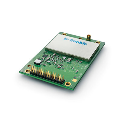
Photo: Trimble
The Trimble BD9250 dual-frequency receiver module supports Trimble RTX correction services and is designed to deliver high-accuracy positioning for high-volume, autonomous-ready applications in agriculture, construction, robotics and logistics. The compact receiver has an industry-standard form factor and pinout, allowing for easy system integration and configuration. Equipped with Trimble’s advanced ProPoint positioning engine, the BD9250 delivers robust and accurate positioning. It is compatible with Trimble RTX correction services or real-time kinematic (RTK) and supports GPS, Galileo, GLONASS and BeiDou as well as QZSS and NavIC. Support for the Indian NavIC S-Band signal is also available.
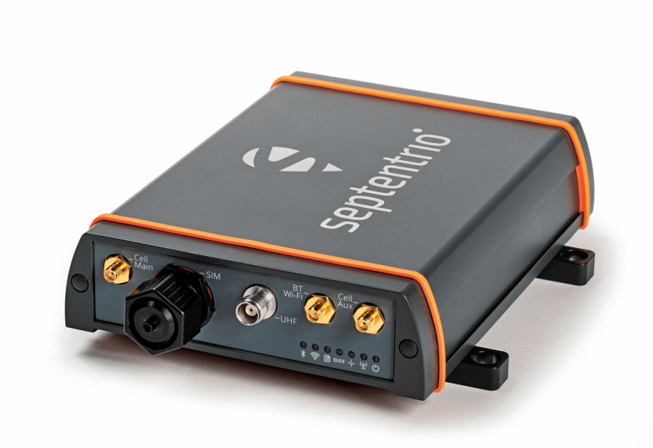
The AsteRx-U3 ruggedized GNSS receiver is the successor to the AsteRx-U for construction, mining and other machine control applications. It combines a triple-band precise positioning GNSS core with extended wireless communication features including Wi-Fi, UHF and 4G LTE, making it easy to fit it into any control system. The AsteRx-U3 offers low latency of under 10 msec with a high data rate, which allows machines to work rapidly and accurately. An IP68-rated housing, with fixing brackets and robust M12 connectors, enables quick installation.
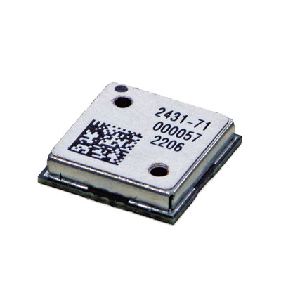
The M20071 integrated GNSS receiver module, measuring 9 x 9 x 1.8 mm, incorporates the MediaTek AG3335MN flash chip. The receiver tracks four GNSS constellations concurrently (GPS + Galileo + GLONASS + BeiDou). The 1.8-volt system power supply provides outstanding low power consumption. Its multipath algorithms improve position accuracy in inner-city environments. The onboard low noise amplifier provides good performance in weak signal environments such as wearable devices.
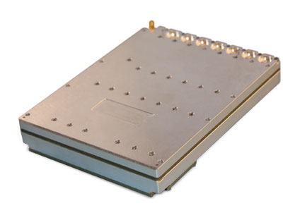
The Strategic Anti-jam Beamforming Receiver – M-Code (SABR-M) enables precise geolocation and strike capabilities in highly contested battlespaces. It integrates receiver technology with advanced antenna electronics in a small, hardened package designed to meet challenging performance requirements. It delivers accurate position, velocity, altitude and timing data, as well as strong protection against GPS signal jamming and spoofing. At 4.5 x 6 x 1 inches, the SABR-M meets size, weight, power, cost (SWaP-C) and thermal requirements for space-constrained military applications. It uses advanced beamforming technology to improve GPS signal reception and counter threat signals.
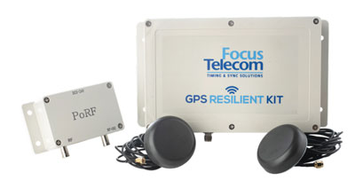
The GPS Resilient Kit (GRK) is a cybersecurity device that comes with two antennas for monitoring and protecting time-critical infrastructures. It can be integrated with any GNSS receiver, either as a retrofit or in greenfield deployment. The GRK features a proprietary interference filtering algorithm for maximum protection, up to 40-dB attenuation of jamming signals with the premium option. It requires minimal power consumption while providing cloud-based monitoring with real-time reporting of jamming attacks. It protects GPS L1 (C/A code) with a latency of 100 ns ±15 ns (fixed).
GBaaS enables providers to combat PNT cyberattacks
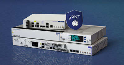
Photo: ADVA
GNSS-backup-as-a-service (GBaaS) enables service providers to help operators safeguard services that rely on positioning, navigation and timing (PNT). In-network timing based on network time protocols (NTP) and precision time protocols (PTP) are also increasingly vulnerable to cyber threats. GBaas is based on ADVA’s aPNT+ platform, which leverages a suite of technologies, including multi-band GNSS receivers and management software based on artificial intelligence and machine-learning. Service providers can offer ADVA’s aPNT+ protection as a subscription-based service as part of their service-level agreements.
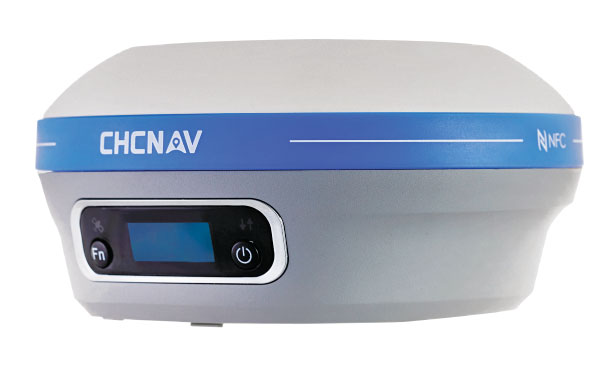
The i73+ pocket-sized receiver is a powerful and versatile receiver with an integrated UHF modem that delivers survey-grade accuracy in all jobsite configurations. It has 624 GNSS channels and the latest iStar technology and can be operated as either a base station or a rover. The i73+ is a highly productive NTRIP rover when used with a handheld controller or tablet and connected to a GNSS RTK network via CHCNAV LandStar field software. The receiver takes advantage of GPS, GLONASS, Galileo and BeiDou, in particular the latest BeiDou 3 signal, to provide robust data quality at all times.
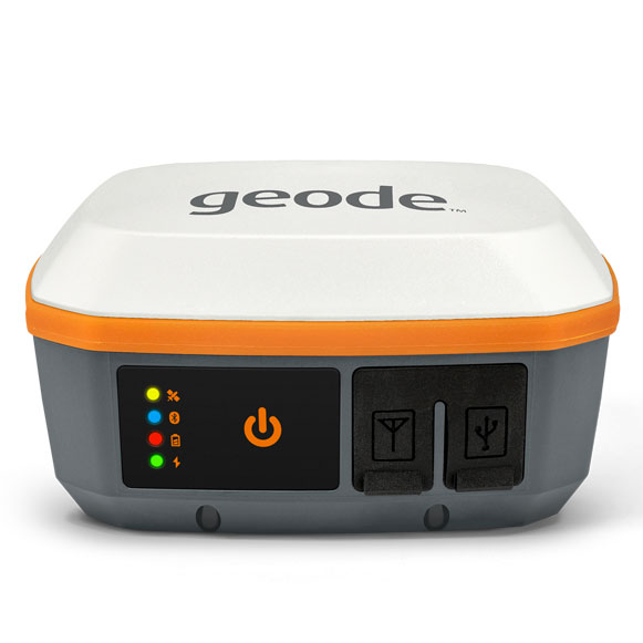
The Geode GNS3 GNSS receiver allows users to collect real-time GNSS data with sub-meter, sub-foot and decimeter accuracy options. With a scalable accuracy platform, users can purchase what they need now, while having the option to increase accuracy in the future. It offers sub-meter accuracy with a single-frequency antenna, while its multi-frequency antenna supports all constellations on L1, L2 and L5. Atlas L-band corrections allow the Geode to be used in water utility locating, agriculture and irrigation mapping, as well as mapping projects in remote locations where other correction services are not available. The Geode GNS3 can be used with Windows, Android, iPhone and iPad devices.
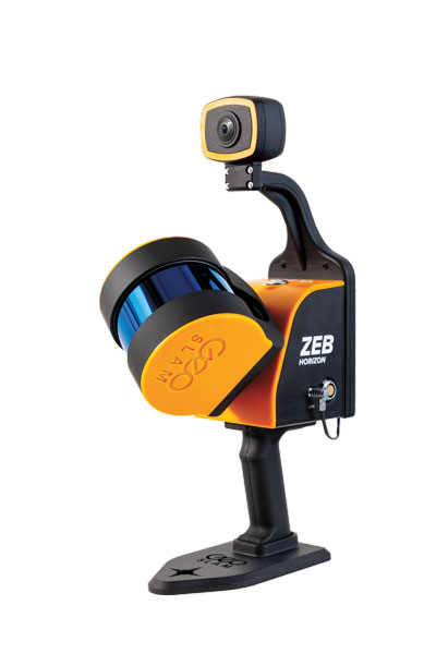
Improved colorization to contextualize point clouds
Photo: GeoSLAM
The ZEB Vision is a camera accessory for the ZEB Horizon system that can be used to capture 360° panoramic photography in 4K definition for point cloud colorization. Data is captured as the user walks through the area of interest. The ZEB Vision uses GeoSLAM’s SLAM algorithm to automatically and accurately position panoramic photos on a point cloud for an interactive viewing experience. The ZEB Vision attaches easily to the ZEB Horizon. The 4K resolution increases feature definition of objects within the point cloud, allowing for a new perspective on data by navigating within a virtual representation of an environment. This means industries such as architecture, construction and facilities can add real-world context to point clouds for the creation of CAD/BIM models.
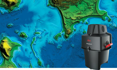
The Leica Chiroptera-5 is a high-performance airborne bathymetric lidar sensor for coastal and inland water surveys. It combines airborne bathymetric and topographic lidar sensors with a four-band camera to collect seamless data from the seabed to land. Compared to previous models, the Chiroptera-5 provides 40% higher point density, a 20% increase in water-depth penetration, and improved topographic sensitivity for generating more detailed hydrographic maps. Its high-resolution lidar data supports nautical charting, coastal infrastructure planning, environmental monitoring and landslide and erosion risk assessments.
The Clirio application combines mobile lidar 3D scanning with smart remote collaboration tools to offer teams an end-to-end 3D solution to capture, organize, share and problem-solve. This is all based on real-time field observations and data, whether team members are on site or a continent away. Clirio is a set of mobile, web and VR/AR apps for instantly capturing, sharing, reviewing and resolving worksite field observations. At a field site, Clirio users collect notes, photos and 3D scans (using the laser scanner built into a new iPad Pro or iPhone Pro). These field observations are automatically geo-referenced within the map-based workspace and synced to a secure cloud workspace. An intuitive interface allows colleagues, managers, partners, or stakeholders to sort, review, compare, and act on field observations.
The Visual Parking System (VPS) by Bird is designed to keep track of scooter parking in a scalable, efficient and vandalism-immune way that requires zero infrastructure within a community. Powered by Google’s ARCore Geospatial API, VPS enables scooter parking with pinpoint accuracy. When parking a scooter, riders will be prompted to take a quick scan of their surroundings. The system seamlessly compares a rider’s images against Google’s data and Street View images in real time to produce the best available parking solution. Stationary objects such as buildings and signs are used as reference points, while more dynamic objects such as people and vehicles are disregarded. The near-instantaneous process results in a precise, centimeter-level geolocation that enables Bird VPS to detect and prevent improper parking with extreme accuracy, helping ensure Bird vehicles are only left in approved areas.
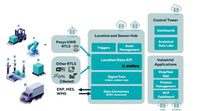
Supports Industry 4.0 with real-time visibility of assets
Photo: Pozyx
The Pozyx Platform is an asset tracking and identification solution for seamless indoor and outdoor tracking, following packages or other assets from trucks to their destination. It is based on the omlox hub, an open standard for real-time location systems that combines GPS data with data from ultra-wideband, 5G, radio-frequency identification, Wi-Fi and Bluetooth. The Pozyx Platform offers a seamless indoor/outdoor transition with zoom-in from a worldwide map to a detailed indoor map, showing highly accurate locations up to 10 cm. It is designed for smart manufacturing, providing a supply-chain solution that supports Industry 4.0. It tracks and identifies any asset, providing real-time data to facilitate warehouse and inventory control, keep track of critical tools, and slash lost asset costs.
ITU is the United Nations agency that deals with information and communications technology. Its remit includes coordinating spectrum use and satellite orbits.
ITU’s Radio Communications Bureau sponsors the World Radiocommunication Conference every three to four years. The issue of interference with GNSS signals was reported at the 2019 conference.
Since that time, according to this month’s circular, the group “has been informed of a significant number of cases of harmful interference to the radionavigation-satellite service…”
Despite concerns expressed by maritime and other interests, the circular focuses entirely on aviation interference. It says the reports it has received have been about “receivers onboard aircrafts and causing degradation or total loss of the service for passenger, cargo and humanitarian flights…” These have included “misleading information provided by RNSS [radionavigation satellite service] receivers to pilots.” An often cited example of this is a well-publicized 2019 incident in Sun Valley, Idaho. In that case a passenger aircraft nearly hit a mountain.
Describing interference with GNSS as a global and recurrent problem, the circular cites data collected by a major aircraft manufacturer. The company found “10,843 radio-frequency interference events … globally in 2021. The majority of these events occurred in the Middle East region, but several events were also detected in the European, North American and Asian regions.”
This year’s uptick in GNSS interference in Scandinavia, the Baltics, and around Ukraine since Russia’s February invasion of Ukraine is not mentioned. This is likely due, in part, to timing. ITU’s Radio Regulations Board met in March 2022 and directed the circular be issued.
Many within the positioning, navigation, and timing community have long asserted that interference with GNSS signals, whether deliberate or accidental, constitutes a violation of ITU rules and regulations. This month’s circular affirms this and cites several applicable provisions.
These include prohibitions on harmful interference with any authorized radio frequency transmission, requirements for users to transmit only in bands for which they have authorization, and for all to generally safeguard aviation operations.
The circular highlights provision 15.1 of ITU’s Radio Regulations as particularly applicable. It states:
“All stations are forbidden to carry out unnecessary transmissions, or the transmission of superfluous signals, or the transmission of false or misleading signals, or the transmission of signals without identification…”
As is the case with almost all international agreements, enforcement of ITU rules is the responsibility of its member states.
While most expect the advisory to have little immediate impact on reducing global interference with GNSS signals, it does help reinforce the issue as one of international concern.
According to a retired government official, “Member states that fail to comply with international rules to which they have agreed lose credibility and standing in the community of nations. Even when they have little credibility or standing to begin with, the behavior adds to their marginalization and life is just a little more difficult for them. This can, in the long run, nudge them toward being more responsible players.”
By Xavier Leblan and Giuseppe Rotondo, GUIDE-GNSS, Toulouse, France Miguel Ortiz, Université Gustave Eiffel, Nantes, France and Christelle Dulery,CNES (French Space Agency), Toulouse, France
Geolocation errors, degraded signal and environmental masking
In a perfect world, the positions calculated by trilateration using the signals transmitted by GNSS satellites would always be accurate to within a few centimeters. Unfortunately, in addition to the intrinsic quality of the receivers, many factors alter the measurements made by a GNSS receiver and degrade the final geolocation data.
To begin with, the GNSS system itself suffers from multiple imperfections including so-called “global” errors. For this reason, the satellite navigation system is complemented with the broadcasting of assistance messages to increase the performance of receivers compatible with SBAS systems, such as EGNOS for the European continent.
In addition, for terrestrial applications, the satellite signals are affected by several phenomena caused by the immediate surroundings of the receiving antenna. These are the so-called “local” errors, such as terrain, bridges, infrastructures, vegetation and interference of any type. Depending on the areas covered, the trajectories calculated by the terminals deviate more or less from that actually taken by the vehicle (antenna), i.e. the “reference trajectory,” also called “ground truth.”
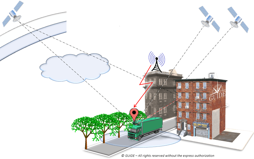
Figure 1. Sources of error in urban geolocation. (Image: GNSS-GUIDE)
Sources of error in urban geolocation include:
Global errors
Orbits and clocks
Satellite geometries
Ionosphere, troposphere
Local errors
Obstruction, attenuation
Multipath and diffraction
Interference, jamming, spoofing
Terminal errors
Receiving chain
Algorithms and services
Navigation sensors
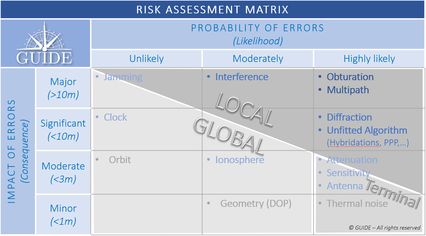
Classification of position errors
To study those phenomena having the greatest impact and likely to be the most frequent, the different types of errors are displayed as a risk matrix. As the “global” errors can be considered to be handled by the regional SBAS system, the pre-eminence of the so-called “local” errors should be addressed.
Figure 2. GNSS Risk Matrix. (Image: Authors)
Description of the main sources of local errors
To observe the effects of local phenomena on the propagation of signals, a dozen identical receivers — with the same configuration and sharing the same antenna — were mounted on a vehicle and driven through urban and peri-urban areas.
We focus on four particularly impacting phenomena to visualize the trajectories calculated by the receivers.
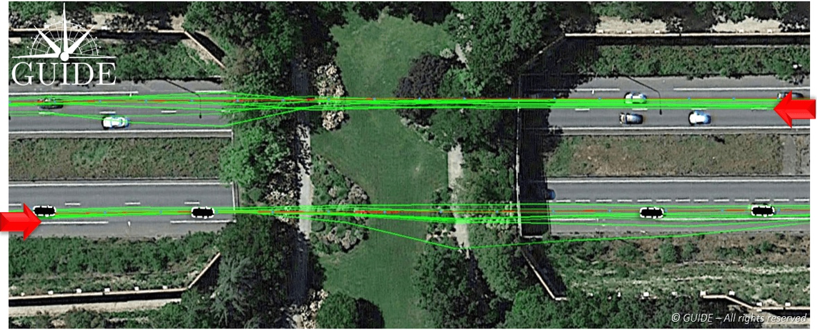
Positioning errors due to bridges
In the picture, below, the test vehicle passes under a bridge in both directions. In both cases, the trajectories diverge under the bridge and converge further on. Here it is easy to understand the shortcomings of results based on a single pass, in other words based on a single measurement.
Figure 3. Effect of alteration of GNSS signals on receivers passing under a bridge. (Image: Auhors)
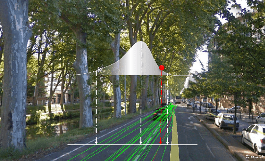
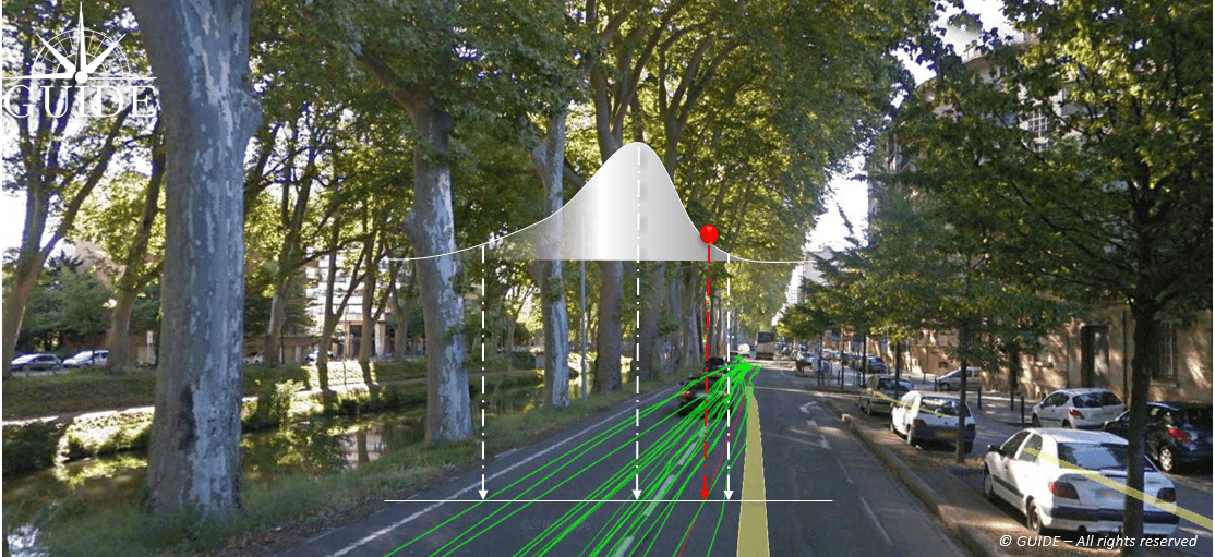
Positioning errors due to vegetation
In the image below, the test vehicle is on an avenue lined by trees whose branches and canopy cover the road. The foliage attenuates and, more importantly, diffracts the radio waves arriving from the satellites, thus degrading signal reception. This results in dispersed trajectories. Each receiver provides a different measurement. Note that due to the proximity of buildings, the center of the position distribution, in the presence of multipath, deviates slightly from the reference trajectory.
Figure 4. Effect of diffraction of GNSS signals on receivers passing under tree canopies. (Image: Authors)
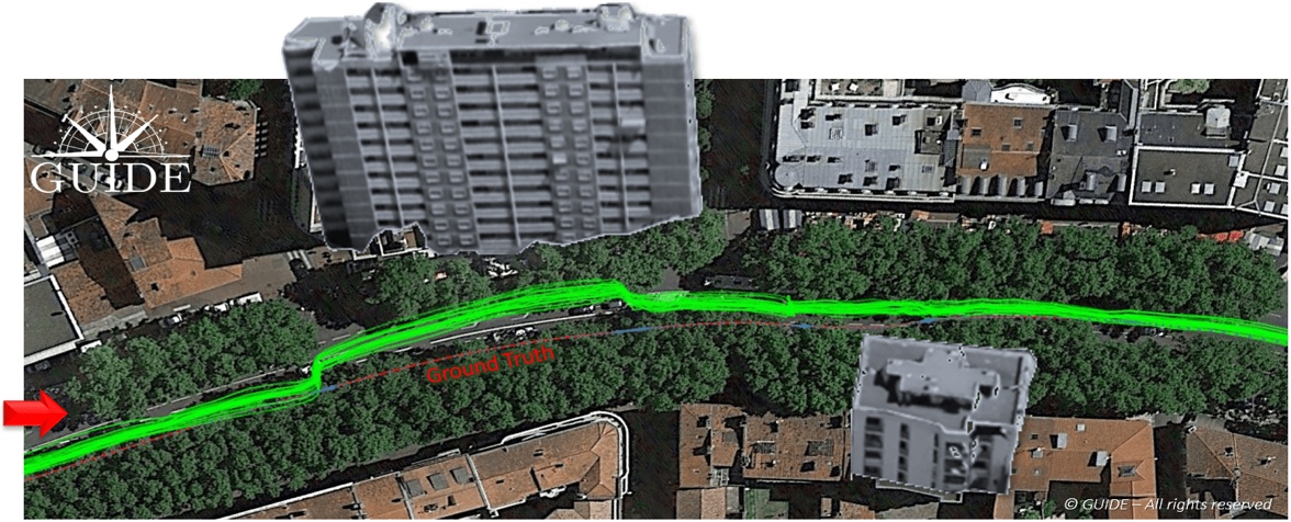
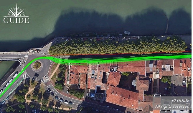
Positioning errors due to buildings
In the composite image (in order to show the main building) below, all the receiver trajectories are deviated towards the building alongside the avenue. The situation highlights the consequences of a phenomenon called “multipath.” When a receiver captures reflected waves, the signal propagation time — used to calculate the pseudoranges — is increased and the accuracy of the end position is degraded. This effect is well known and easily observable during static measurements.
Figure 5. Effects of GNSS signal propagation on receivers near a building. (Image: Authors)
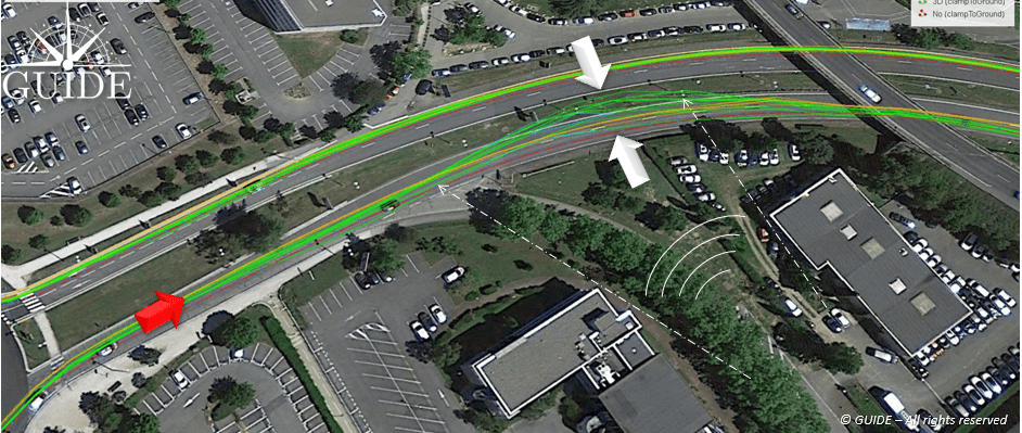
Positioning errors due to interferences
In the image below, the on-board receivers have been disturbed by “transitory” interference. On the outward journey, twenty minutes earlier, no problem had been detected for the trajectories on the other side of the expressway.
On the return journey, this unidentified interference degrades the accuracy of the receivers with a visible dispersion of the trajectories. In other situations, intentional or unintentional interference could completely block out the GNSS band preventing any position measurement.
In this case, the source of the interference seems to come from the bottom right, guided by the two parallel buildings.
Figure 6. Effect of unidentified temporary interference on signals for GNSS receiver. (Image: Authors)
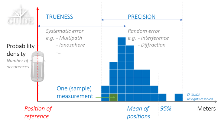
Trueness and precision of position measurements
Receivers of the same batch behave differently depending on the environment. For a predominantly multipath situation, they all converge to the same wrong position. On the other hand, when the propagation phenomena become more complex with multiple diffractions, such as reception under foliage, each receiver produces a position with a different error. For complex environments, we have a combination of these two behaviors.
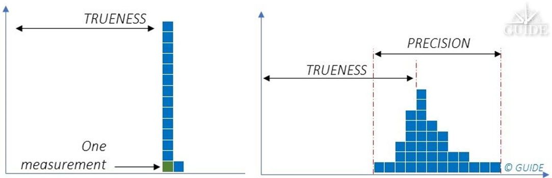
The first behavior is deterministic. Metrology uses the term measurement “trueness,” which stands for “closeness of agreement between the average of an infinite number of replicated measured values and a reference value.”
The second behavior is non-deterministic. In this case, metrology uses the term measurement “precision,” which stands for “closeness of agreement between indications or measured values obtained by replicated measurements on the same or similar objects under specified conditions.”
Terrestrial applications often offer a varied mix of environments where “trueness” and “precision” errors accumulate. It is essential to consider both components in order to characterize and study GNSS receiver performance.
Statistic distribution of the different positioning errors:
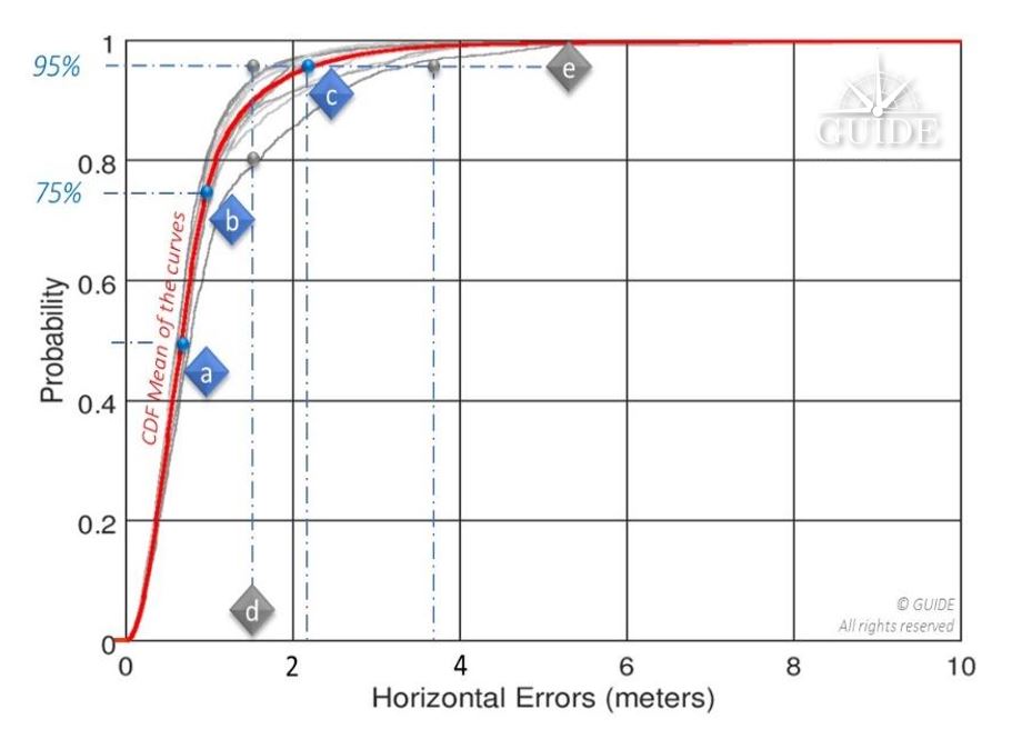
Figure 7. Combination of deterministic and non-deterministic errors. (Image: Authors)Figure 8. A single position measurement at a point has two unknowns: The weight of deterministic (trueness) errors compared to those that are not (precision). (Image: Authors)Figure 9. Statistical distributions of errors for a trajectory (scenario), that is the percentage of all errors (probability) lying beneath a given accuracy level. (Image: Authors)
Above, 95% of the positions calculated during a replay have an accuracy better than 1.5m; this same value is only reached with ~80% of the positions calculated during another replay — see vertical line [d]. The horizontal line [e] illustrates the spread of the horizontal position by considering 95% of the positions of two replays: for one the displayed accuracy is ~ 1.5m and for the other it is degraded to 3.5 m. This curve will always point to the same reference points [a], [b] and [c] recommended by the standard EN16803-1 and corresponds to the percentage of measurements respectively less than 50%, 75% and 95%.
By way of example, the evaluation of a single receiver on board a vehicle travelling in an urban environment does not allow separation of these two components. Indeed, signal degradation determines the degree of dispersion of the “random” component of the measurements. Thus, in certain environments, each additional receiver will produce a different result. However, the analyses of a single onsite campaign relies on just one single sample (single trajectory of the terminal under test), where a panel of measurements is essential. In fact, the available statistics prove insufficient to characterize a receiver, even at the cost of doing long runs.
Figure 10. Visualization of the combined deterministic and non-deterministic errors. (Image: Authors)
Live testing is therefore rather intended for final integration.
On the other hand, a constellation generator will synthesize ideal signals derived from mathematical models, and, in any case, not representative of the real environment. The measurements will then only be deterministic, that is, subject to “systematic” errors. Repeated simulations on the same receiver will always produce the same measurements. Nevertheless, this type of test bench offers many advantages for simulating unobservable situations in the real world.
Disparities in analysis possibilities on position errors based on:
Figure 11. Typical results for repeated measurements obtained, respectively from left to right, with synthetic signals and real-world signals. (Image: Authors)
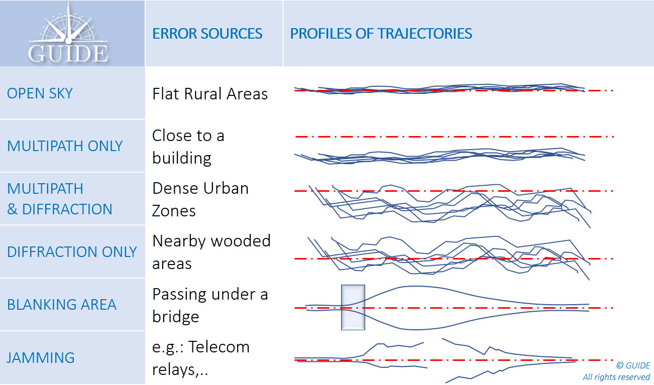
In summary, the main error profiles are described below.
Each situation combines both trueness and precision errors. This latter component requires several runs in the same configuration to determine the potential measurement spread.
Figure 12. Position error profiles (measured trajectories/DUT) depending on the environment. (Image: Authors)
What is GNSS metrology?
As a first approach, characterization of GNSS performance would require many receivers on the same test vehicle. This method is certainly useful in the experimental stage, especially to understand the impact of propagation phenomena on positioning errors. However, it has major disadvantages, both from a logistics point of view and because of the basic metrological requirements.
To obtain reliable and useful measurements, from an operational point of view, the tests must be “representative” of the areas to be covered and “reproducible” to check the results and make valid comparisons, for example, between two receivers, two firmwares, two settings, two antennas and even two hybridizations.
Under these conditions, replay techniques, often referred to as “record and replay,” meet the expected requirements. For the record, this metrology method consists in digitizing the GNSS signals received by the antenna on board the definition vehicle, taking care to collect all the data associated with the tests (VIDEO, INS, DMI, NRTK, …), above all, the ground truth. Thus, at the end of the campaign the GNSS signals and other data are synchronized and restored on a replay bench consisting of an “SDR replayer.”
Replaying the same scenario on a receiver makes it possible to reproduce the recording conditions identically. Each pass generates new measurements, equivalent to using an additional unit, virtually onboard. Compiling the results thus highlights the non-deterministic errors, that is, those which by their random nature emerge from the others.
Test laboratories such as GNSS GUIDE design and market test data that can be replayed directly on the main simulation instruments capable of operating in two modes: simulation and replay. The replay configurations are generally much more affordable than the larger, structurally more complex constellation generators. In addition, the implementation of replay sessions is simple, fast and requires no special training.
In addition to scenarios made on request, the available libraries already cover a multitude of cases, previously inaccessible for an isolated user. They open up the possibility of testing terminals in different latitudes with varied terrain and neighborhoods composed of typical architectures.
Conclusion
The French Space Agency (CNES) has financed several R & D contracts for the development and validation of this replay technique (record and replay). It is already recommended by CEN / CENELEC through the series of EN16803 standards to characterize and classify the performance of GNSS terminals. This methodology complies with the basic principles of metrology.
The test conditions are reproducible and representative of operational conditions. The measurements are repeatable and allow separating the systematic errors (trueness) from the random errors (precision). Measurement uncertainties are also accurately established.
During an on-site measurement campaign, the statistical distributions of two identical receivers on board the same vehicle lead to different results. Thus, no characterization can be established at this stage.
With a replay bench, after several iterations of the same scenario, the average values of the measurements on a CDF tend toward a curve characterizing the performance for that scenario.
Instrumentation dedicated to replay operations is less complex and less expensive. Statistical models of simulations are replaced by scenarios of GNSS signals previously digitized in the field or on constellation generators. Thus, whether they come from a real or synthetic environment, these GNSS signals are easily restored, while drastically reducing the preparation and execution times. The economic benefits of this test technique are now evident and are favoring its adoption by the transportation industries.
References
Niels Joubert, Tyler G.R. Reid, and Fergus Noble (2020), Developments in Modern GNSS and Its Impact on Autonomous Vehicle Architectures
Andrej Tern and Anton Kos (2018), Positioning Performance Assessment of Geodetic, Automotive, and Smartphone GNSS Receivers in Standardized Road Scenarios
Ni Zhu, Juliette Marais, David Betaille, Marion Berbineau (2018), GNSS Position Integrity in Urban Environments
C. Rouch, B. Bonhoure, F.X. Marmet, T. Chapuis, H. Secretan, V. Bienfait, X. Leblan (2016), Measurement campaigns and PVT experiments with new Galileo satellites
B. Calvet, L. Montoya, P. Grandjean, X. Leblan (2015), The GUIDE High-Precision test facility (GNSS laboratory)
G. Duchâteau, X. Leblan, Y. Capelle, W. Vigneau and F. Peyret (2014), Certification of Road User Charging: Approach, standardization and role of laboratories
Interview with Sara Masterson, Director, Positioning Services, Hexagon’s Autonomy & Positioning division, Hexagon | NovAtel
The accuracy of GNSS receivers continues to increase thanks to new satellites and signals, improved antennas, etc. How is that changing the role of correction services?
For sure, the accuracy of GNSS receivers and antennas is improving. However, most applications still require a higher level of accuracy than what is available from an uncorrected position even with the positioning improvements brought by new constellations and signals. GNSS corrections are still required to enable, say, lane-level accuracy, or sidewalk-block accuracy for autonomous driving or mobile phone applications and for off-road autonomy applications such as construction, mining, agriculture — these all still require centimeter-level accuracy that is enabled through GNSS correction services.
Corrections also help by improving the availability and reliability of a solution. In the future, corrections will play a key role in adding integrity to enable functionally safe solutions that are required for new applications, such as autonomous driving.
There are many options for corrections — local, regional and global, ground-based and satellite-based, public and private, etc. Which of them are generally best for which applications and conditions?
That depends very much on the user and the application. There are many new correction services in the market. Some are free, some are commercial services. Even now we see in agriculture that WAAS is sufficient for some broadacre-type applications. So, we will continue to see a range of applications, some of which will be satisfied with the level of performance from a free service and others that will be looking for the better performance and service level guarantees that come with commercial services.
If something is not working when you are using a free service, there’s no one to call. With commercial services, you get responsive customer support and you pay for higher levels of performance and service availability. In many applications, especially those that involve autonomy or safety applications, you cannot afford to have downtime, or your machine just stops working, which costs money. So, many applications are still going to be needing the performance and service level guarantee that commercial services offer.
How does TerraStar fit into this range of options? What industries and applications are you targeting?
TerraStar has a range of services that enable us to target many industries and applications. Agriculture, of course, is one of the key applications for our services and we have customers using TerraStar for mobile mapping, UAVs and new autonomy-based applications. We are also involved with some interesting Hexagon joint projects that use TerraStar corrections for mine train automation and surveying and construction.
Our entry-level TerraStar-L service is still better in performance to many of the free services or to an SBAS-type service in terms of accuracy, but it is available globally, including regions where you don’t have other options. It also provides better pass-to-pass and year-over-year repeatability, as well as very quick reconvergence time if there are any issues with GNSS outages.
Our flagship offering is the TerraStar-C PRO service. That’s where we just introduced the “RTK from The Sky” technology, bringing the performance down to converging to two and a half centimeters in three minutes. That, too, is available globally which makes it a real game changer for customers in many different applications, because they can start to look at that service as an alternative to RTK and without the added connectivity logistics that an RTK solution brings.
Our RTK assist solutions are good augmentation solutions for customers who still primarily need RTK but experience some RTK correction outages – RTK ASSIST bridges through those outages. So, we have a wide range of service offerings in the portfolio that can address the positioning needs of many applications.
Photo: Hexagon | NovAtel
Will the reasons for having a base and rover setup decrease sharply?
Use of base and rover setups is already decreasing and being replaced by both PPP and network RTK solutions. There are applications where RTK still makes sense, such as those that have very tight vertical requirements and many survey applications. Another Hexagon division, Hexagon’s Geosystems division, incorporates TerraStar correction data into their new SmartNet Global offering as a seamless service that provides both SmartNet RTK plus TerraStar for either bridging outages or independent PPP operation, depending on the project’s location and whether they’re within range of SmartNet coverage.
There will be many applications that continue to benefit from a combination of the two technologies. However, as the PPP services, like TerraStar, continue to improve by reducing convergence time and providing highly reliable solutions, users in those applications can be confident that the standalone PPP solutions meet their performance needs and bring many additional benefits such as consistent, global coverage and performance.
Is TerraStar completely receiver agnostic?
TerraStar is currently only compatible with NovAtel’s GNSS hardware. Going forward, through the work that I referenced with autonomous driving and mass-market applications, we will be providing TerraStar services in industry-standard formats, depending on the inter-operability requirements coming from those applications. We expect that there will be demand for dual sourcing of corrections and interoperability between chipsets that are used in vehicles, for example. For those applications, we will be developing TerraStar services that are compatible with hardware from other GNSS manufacturers.
The companies on June 29 signed a precise-positioning business partnership agreement that KT hopes will enable precision location services for autonomous vehicles, drones and urban air mobility.
Swift Navigation’s precise-positioning platform improves location accuracy from several meters to centimeters, enabling safer driving, improved efficiency for last-mile delivery and commercial transport operations, and enhanced accuracy for mobile devices.
Skydel 22.5 features advanced hardware-in-the-loop testing
Orolia has released Skydel 22.5, a significant software upgrade to its Skydel simulation product line that features advanced hardware-in-the-loop (HIL) testing solutions providing very low to zero effective latency.
The enhanced visualization tools can monitor internal latency through real-time curves showing when the data is generated and sent to the RF signal. Users can also review the transmission of HIL packets for optimizing the entire network’s latency, checking its stability (jitter), and that data is available and used at the right time in Skydel.
HIL testing is an essential step in the verification process of the model-based design (MBD) approach because it involves all the hardware and software that will be used operationally. HIL verification can test a standalone device-under-test (DUT) or, more generally, an entire complex system consisting of multiple DUTs in both open- and closed-loop architectures.
“The vast majority of problems encountered by engineers on HIL systems are related to poor control of the latency of the entire simulation chain, as they are insufficiently accessible, transparent and controlled on the competing systems,” said Pierre-Marie Le Veel, principal system architect and product manager for GNSS simulation. “Thanks to these tools, our high-end performance and well-known intuitive automation, Skydel dramatically reduces the implementation time of a HIL system (which can be very significant) and, therefore, the project’s overall cost.”
Photo: Orolia
In addition to these tools, Skydel implements modern extrapolation algorithms that achieve zero effective latency. These algorithms make it possible to keep position errors negligible, even for equipment with very high dynamics used in national defense applications such as missiles, rockets and guided shells.
“These advanced HIL algorithms and tools are available – and with the same performance – on our Wavefront simulation systems to test controlled reception pattern antenna (CRPA) systems,” Le Veel added.
Additional constellations, signal types and options such as real-time kinematic (RTK) and multi-instance are available along with dedicated bundled simulation starter packages for automotive.
The upgrade is available at no additional cost for existing users operating Skydel 22.5. Application notes, support documents and tutorials are available online.
South Korea has successfully launched a precision aviation satellite Thursday by leasing space on Malaysia’s MEASAT-3d communication satellite for 15 years, reports The Korea Herald. The first satellite for the Korea Augmentation Satellite System (KASS) will improve the accuracy and reliability of GPS signals for pilots, increasing airline flight safety.
The satellite lifted off from Guiana Space Center in Kourou in French Guiana at 6:50 a.m. Thursday (Seoul time), and successfully separated from the rocket at around 7:18 a.m. after the fairing and first stage rocket separations.
In development since 2014, the KASS system can improve the GPS position error to 1.0 to 1.6 meters from the current 15-33 meter level in real time to ensure positioning reliability throughout the country.
The government plans to begin a pilot service around December before its full-fledged operation next year.
South Korea is the seventh country to have a geosynchronous satellite system officially registered with the International Civil Aviation Organization (ICAO). The others are the United States, Russia, China, the European Union, India and Japan.
The Korea Augmentation Satellite System will improve airline safety over Korea. (Photo: ugurhan /iStock/Getty Images Plus/Getty Images)