Category: Defense

  • eLoran and UrsaNav: Timing Is Everything

    The first part of the recent UrsaNav press release says it best:

    This week for the first time since August 2010 advanced low frequency (LF) signals, including a new eLORAN, are on the air in North America! As a result of a Cooperative Research and Development Agreement (CRADA) between the United States Coast Guard (USCG) and UrsaNav, Inc. live testing of a wide-area precise timing solution has begun. These initial tests include a comprehensive pallet of signals, including eLoran, that are being evaluated for their ability to provide a robust, wide-area, wireless precise timing alternative that can operate cooperatively with GPS, or during periods of GPS unavailability.

    Why eLORAN

    Global government, industry, and academic experts recognize that advanced LF signals, of which eLORAN is just one example, can provide alternative timing — either as a stand-a-lone service, or as a component of an existing PNT service. The high power, virtually jam proof and spoof proof LF signals operate independently of GPS and GNSS, and provide a Universal Coordinated Time (UTC) time reference in the order of tens of nanoseconds. The recognition of the criticality of time to many aspects of our national critical infrastructure has led to establishment of the CRADA to evaluate the benefits of an LF wide-area timing system.

    UrsaNav on-air eLORAN tests continue at various sites throughout the United States (CONUS and Alaska). Broadcast demonstrations will test several different frequencies, waveforms, and modulation techniques using evolutionary state-of-the-art technology.

    Reception demonstrations of the eLORAN broadcasts are planned at both on- and offshore locations, and will include advanced LF data delivery techniques. Trial results will be presented at national and international conferences. Anyone interested in any part of the testing or interested in making their own measurements are invited to contact UrsaNav.
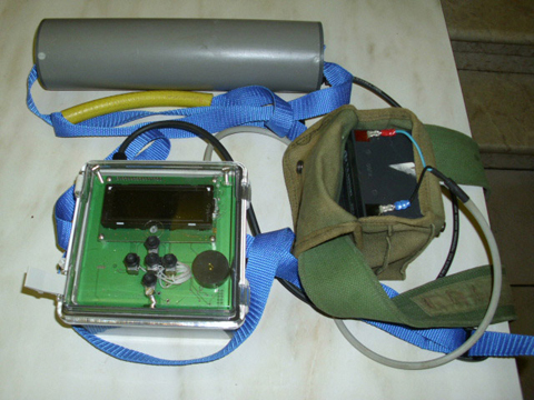

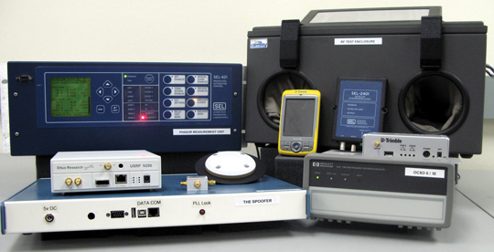
    UrsaNav eLORAN system. Arthur Helwig (UrsaNav) and
    Aaron Grant (Nautel) prepare the LF transmitter for the next
    set of on-air tests.

    Partnered with Symmetricom and Nautel, UrsaNav says it has the world’s most advanced LF alternate PNT and data solutions to include the world’s best high-performance eLORAN timing receivers. UrsaNav has partnered with two of the best in the business for timing and transmitters, and this alliance of expertise provides the foundation technology for the best wide-area terrestrial-based alternative to GNSS such as GPS, GLONASS, and Galileo.

    That being said, I would add that you should not only consider the UrsaNav LF system as an alternative, but during normal GPS operations as a complimentary and/or augmentation to GPS, and then as a back-up and integrity system when the situation warrants.

    As one of my professional colleagues, who is a retired USCG officer and once ran the USCG Navigation Center, stated, “This is a big deal! It is in fact the first and biggest piece of good news about a true PNT (position, navigation, and timing) backup for GPS since Loran-C was killed in the FY2010 budget.

    “Not only is this an independent timing backup, but the LF signals can also be used as pseudoranges mixed in with GPS, or if enough transmitters are available, as a fully independent PNT network. In other words, a true backup PNT capability for safety-of-life navigation, for dispatching first responders, and for supporting critical national infrastructures.”

    This is a pretty enthusiastic response, even from a LORAN aficionado, and it is indicative of the responses I received whenever I reached out for comments from knowledgeable PNT SMEs (subject matter experts) around the globe.

    The response nationally and internationally has been extremely positive as well — especially in light of the recent LightSquared debacle and the now better-understood vulnerabilities of the very low-power GPS signals.

    I hoped I would never have to type or have you read that word again, as a noun or a verb, but the whole LightSquared scenario did serve to point out a dire need and shortcoming in the U.S. PNT infrastructure. Fortunately, the proposed UrsaNav eLORAN system appears to be on track to fill that need perfectly.

    For the first 32 years that GPS signals were broadcast, LORAN-C served as a critical backup for timing and a less accurate but viable alternative for navigation. In fact, Loran-C, along with GPS and cesium clocks synchronized to UTC, were the only accepted Stratum 1 frequency sources at the time (Stratum 1 frequency sources provide a minimum frequency stability of 1 x 10-11 per day.). Then in 2010 the current U.S. administration was looking for government programs to cut and for some unknown reason they latched onto LORAN-C, which was in a critical state of transition at the time.

    LORAN-C has been around since World War II. I among many other aviators used it extensively in Vietnam, and frankly for many countries and users today it is still a totally adequate service. With USCG expertise and support for 52 years, LORAN-C provided unparalleled timing and navigation services around the United States and Canada until the pretender known as GPS came along and dethroned the aging monarch.

    Now, that may sound like a natural sequence of events, except that LORAN-C was in metamorphosis, 80% of the way through the process actually, of morphing into a new digital (1990s era technology) LORAN know as eLORAN or enhanced LORAN with better, more reliable transmitters, smaller receivers, and a virtually jam-proof signal structure. Many likened the legacy eLORAN to a strong ground-based GPS with coded signals for security. All that was in place and 80% complete when the whole process was killed by an administration with a strong Luddite orientation and subsequently the bean counters pulled the plug in 2010, despite recommendations to complete eLoran from both the Department of Transportation’s Positioning and Navigation (PosNav) Committee and the Department of Homeland Security Geospatial Committee and the strong personal support of the DOT Undersecretary for Policy and the DHS Deputy Undersecretary for Preparedness and National Protection and Programs. My sources tell me the Office of Management and Budget (OMB) was determined to do away with Loran-C and facilitated its ultimate demise. An unfortunate theme we have seen played out much too often: Non-technical people forcing ill-advised technical decisions. In a country whose greatness has always been its technical acumen, willingness to take risks, and self-assurance, OMB stands as a chilling element of focus today…but, that’s a subject for a future article.

    Since that time the U.S. Coast Guard spent more money dismantling the legacy LORAN-C infrastructure and antennas than it would have taken to complete the 20% upgrade for a full transition to eLORAN. Taking down the Port Clarence, Alaska, tower, the video of which was a YouTube favorite for many weeks, cost an estimated $8 million. The destruction of the towers in Attu (right), Shoal Cove and St. Paul were probably on average $5 million each. With the tower removal in Baudette, Minnesota, the cost of removing Loran towers to date cost close to $25 million. One could argue that the administration created some jobs in these “shovel-ready” tower tear downs, but I have no doubt that a better use of the funding would have been to deliver a robust positioning, navigation, and timing backup for the nation. But alas that is ancient history in the technology world, a whole 18 months to be exact.

    Then along comes the Lone Rang… I mean Chuck Schue, the CEO and president of UrsaNav, which is a small company originally founded by Charles “Chuck” Schue, because frankly he has always been interested in navigation. Chuck is a former ION (Institute of Navigation) Washington, D.C., Section Chair and is a current member of the ION Council. Chuck is also a retired USCG officer and his last job in the USCG was as Commanding Officer of the Loran Support Unit, providing direct support to a large portion of the functions supported by the USCG Navigation Center (NAVCEN). So it is no accident that Chuck and UrsaNav saw the gaping hole for GPS support that was created when LORAN-C and the legacy eLORAN programs were unceremoniously put on the chopping block. Now UrsaNav with their new 2012 version of eLORAN and the help of the USCG, through a CRADA, have stepped in to fill a very real need.

    In my opinion (pun intended) their timing could not have been better. LightSquared is hopefully behind us along with the threat of losing GPS capabilities and all GPS P&T (positioning and timing) enables without a viable backup. This is definitely not a scenario any sane person wants to see happen again and fortunately UrsaNav LF timing and eLORAN can provide a critical back-up, augmentation and integrity check while simultaneously providing the USG with a security blanket, as Linus would say.

    The USCG-UrsaNav CRADA

    Before considering reactions from other USG agencies and then international reactions to the UrsaNav program, maybe it would be best, in case any of you are wondering, to describe the function of the subject CRADA since it has been mentioned several times.

    In February 2012 the U.S. Coast Guard Research & Development Center (R&DCEN) announced it had entered into a Cooperative Research and Development Agreement (CRADA) with UrsaNav to research, evaluate, and document at least one alternative to the Global Positioning System (GPS) as a means of providing precise time. The alternative under consideration is a wireless technical approach for providing precise time using U.S. government facilities and frequency authorizations.

    While this is a very general statement and does not give much away, it is meant to be that way since it is, after all, an R&D effort and general statements give you the most leeway when considering options and trade space.

    CRADAs are authorized by the Federal Technology Transfer Act to promote the transfer of technology to the private sector for commercial use as well as specified research and/or development efforts that are consistent with the mission of the federal parties to the CRADA. The federal party or parties (USCG) agree with one or more non-federal parties (UrsaNav) to share research resources, but the federal party does not contribute funding.

    This means that the USCG and UrsaNav are sharing R&D efforts, data, and even non-monetary resources, but the USG is not providing any funding to UrsaNav for the project. So UrsaNav is footing the bill; at the same time, it has access to USG data and resources, to include buildings and transmitting towers, for example, and UrsaNav knows it has at least generated interest among government and commercial users for LF timing signals.

    DOT/FAA Reactions

    When I first saw the UrsaNav announcement, I immediately thought of the DOT and FAA, since they have been trying to think of ways to provide a common, non-GNSS, distributed timing backup for all their facilities and customers as part of their efforts to develop an alternate PNT (APNT) capability. One of the APNT alternatives is considering distributing time to air traffic control facilities and aircraft through their ground-based DME (distance measuring equipment) facilities. For the non-aviators among you, DME signals allow aircraft to determine their distance from a DME location. Properly equipped aircraft (primarily commercial and high-end general aviation) can use ranging from multiple DMEs to actually determine their position and follow area navigation (RNAV) procedures for more effective routing and flexibility. In order to utilize the DMEs as a ground-based, high-power (1000 W) equivalent of a satellite constellation will require each DME facility to be synchronized in time to around 30 nanoseconds or better. Now, with the possibility of an eLORAN time standard with a huge booming, virtually jam-proof and spoof-proof signal, across the CONUS and Alaska, this FAA alternative solution could be greatly facilitated. While the FAA also has the option to use GPS time, or time from its own WAAS ground-based clock ensemble, or WAAS retransmitted time combined with GPS time for remote locations and to back it all up and provide an integrity check, the availability of an eLoran alternative is certainly worthy of FAA APNT consideration. The FAA’s distribution problems would be solved, and since both GPS and eLORAN have the capability for encoded signals, the integrity (information assurance) and security problems are solved as well. Comparison of the vulnerable GNSS signal with the robust eLoran timing signal could alert an operator to possible spoofing or even a less sinister loss of integrity event. So this is a win/win for the FAA and several other critical national agencies and infrastructures that must remain nameless for security purposes.

    International Partners

    What makes the UrsaNav solution so promising and frankly exciting is that they are not conducting these experiments and demonstrations in isolation. For the past few months UrsaNav has been working with the Lighthouse Authorities of the United Kingdom and Northern Ireland as well as Chronos Technology, a world leader in GNSS jamming and interference detection, in Great Britain. To determine how the UrsaNav eLORAN program is progressing internationally, who are you going to call? Personally, if it concerns GPS, time, and the UK, there are two people who immediately come to mind: Dr. David Last and Martin Bransby.

    Professor David Last is a consultant engineer and internationally renowned expert witness specializing in radio navigation and communications systems. David is a Professor Emeritus (that means he is at least as old as I am) at the University of Bangor, Wales, and Past-President of the Royal Institute of Navigation (RIN), the equivalent of the U.S. ION, but RIN has only been around since 1947. David acts as a consultant on radionavigation and communications to companies and to governmental and international organizations worldwide and is active as an expert witness, especially in forensic matters concerning GPS.

    Both David and Martin are highly qualified SMEs and BLUF, or bottom line up front; their praise for the UrsaNav initiative could not be higher.

    According to Professor Last, “…a ‘sky-free’ timing service like the one UrsaNav will hopefully soon be radiating in the United States is already available across the British Isles and adjacent parts of Europe. The eLORAN system uses the GLAs’ prototype eLoran system plus GPS/eLoran timing receivers from UrsaNav and Chronos Technology.

    “The prototype eLoran service has been running 24/7 since January 2008, serving the eastern half of Britain and the North Sea. It now delivers 10-meter (~30 feet) navigation accuracy in the approaches to Harwich and Felixstowe, the UK’s major container ports, where a prototype full differential service has been in place since mid-2010.

    “In addition, the UK transmissions support a prototype robust, nationwide data channel that will benefit in future from the techniques currently being developed by UrsaNav to expand the data capacity of eLoran-compatible LF transmissions.

    “This is all part of the resurgence of terrestrial LF services in response to the vulnerability of GPS and all other GNSS (read LightSquared). The GLAs are leading this movement to adopt eLoran as the terrestrial complement at sea and supporting the use of the new eLoran transmissions for sky-free complementary navigation, timing, data, and tracking of land vehicles. And the neat thing about LF timing and data is that a single station serves a large area. So the UK station delivers data across the UK and timing even more widely. This appeals to all sorts of folks who aren’t interested in navigation. But once enough timing and data stations are on the air, you get back navigation!”

    Now, Martin Bransby is the R&RNAV (Research and Radionavigation) manager for the General Lighthouse Authorities (GLAs) of the UK & Ireland. Which simply means he is a senior engineering manager and program manager with extensive experience in R&D of highly technical assets, such as maritime aids to navigation, radar, C4ISTAR, and tactical data links, and he is the official GLA POC working the eLORAN program in the UK and Ireland, which he indicates is progressing extremely well. So well, in fact, the GLAs awarded a 15-year contract to provide a state-of-the-art eLORAN service to improve the safety of mariners in the UK and Western Europe. The service contract includes R&D work and the operation of an eLORAN service through 2022.

    Support: The Good News

    Back on this side of the pond, my sources at the USNO (U.S. Naval Observatory) our resource for Coordinated Universal Time or UTC are supportive of the UrsaNav eLORAN effort. A senior source, who prefers to remain anonymous, stated that the USNO will support any USG terrestrial time distribution system that may emerge from the UrsaNav eLORAN effort by providing the underlying timing reference “UTC (USNO).” However, to achieve true GPS independence, my source would like to see either fiber-optic or two-way satellite time transfer (TWSTT) utilized to sync the eLORAN ground transmitters. And in the end higher power, GPS independence, and good indoor reception are probably the greatest advantages. My source is looking forward to the results of this initial demonstration by UrsaNav and the USCG.

    According to Chuck Schue, UrsaNav, anticipated this USNO preference and is working with Symmetricom on a TWSTT while also developing a TWLFTT, or two-way low-frequency time transfer capability, which allows for time transfer from a UTC source such as USNO or NIST that is completely sky-free.

    The Bad News

    We’ve all heard the Biblical phrase that originated in Matthew concerning “the right hand not knowing what the left hand is doing.” In this instance, where eLORAN is concerned, the USCG may have adopted that as a program motto.

    Note: The real motto of course is Semper Paratus, and the brave men and women of the USCG live up to it everyday.

    Originally in the Unites States, CONUS, and Alaska, there were 24 LORAN-C transmitters with towers between 600 and 1350 feet tall; add the towers supporting the Joint U.S.-Canadian LORAN-C system plus the LORAN-C Support Unit tower, and there were a total of 30 huge LORAN-C towers with all the accompanying support structures for the transmitters, support crews, etc. Today, there are only 25 towers remaining — as the USCG engineers are in the process of dismantling the LORAN-C infrastructure — five towers in the last 18 months.

    As often happens in a large distributed organization, though Headquarters (CG-5) supports the eLORAN CRADA with UrsaNav and fully realizes that future eLORAN deployment depends on reuse of existing infrastructure, the civil engineering support organization gets its money and develops its project lists separately. Consequently the antenna towers at Attu (located at the end of the Aleutian chain) and Port Clarence (situated well north of Nome) have come down, as have the towers in St. Paul (in the Pribilof Islands, northern Bering Sea) and Shoal Cove (located in SE Alaska, near Ketchikan). Only two towers remain in Alaska; one in Kodiak (adjacent to the USAF-Alaska launch facility) and one at Tok Junction (on the ALCAN Highway, southeast of Fairbanks). Within CONUS, the USCG engineers are in the process of dismantling the facilities in Baudette — which is just about as isolated as some of the sites in Alaska.

    Operational Issues

    The operational problem is that while the much more powerful and economical energy-scavenging transmitters from UrsaNav’s partner Nautel, and new wave forms being produced by UrsaNav, probably only need to utilize 8-10 towers — the system is that much better and more powerful — no one knows where they need to be located until more tests are conducted. So how do the USCG engineers know which ones to dismantle? Obviously they don’t and there’s the rub, plus if the system is really successful and the data portion is a success, there could be a need for even more towers. Solution — the R&D guys (RH) need to coordinate with the engineering crews (LH) and put a hiatus on dismantling LORAN-C towers and the associated infrastructure, unless they pose a safety hazard, until the outcome of the CRADA and subsequent acquisition decisions have been made.

    Seriously, the USCG and UrsaNav are heroes for initiating the CRADA, and my hat is off to them for realizing the critical need for eLORAN, but seriously, somebody pick up a phone and call the engineers, call the Commandant, call somebody that can put the tower demolitions on hold.

    The bottom line is UrsaNav and the USCG are to be congratulated for their foresight and planning. Let’s hope the eLORAN demonstrations continue to be successful and that a contract is forthcoming quickly before we, and the powers that be, forget the LightSquared lessons learned…like we would ever let that happen.

    All in all, this is a win/win proposition for the USCG, the USG, and for GPS users everywhere. Stay tuned for more on this topic.

    While you are reading this I will be attending the Munich Satellite Summit in Germany, so guess what my topic will be next month?

    Until next time, happy navigating.

  • Geospatial Mapping Enhances Arlington National Cemetery Management

    Officials at Arlington National Cemetery will use an Army-designed geospatial mapping system to manage cemetery operations, said the executive director of the Army National Cemeteries Program.


    Kathryn A. Condon testified before the House Veterans Affairs Committee's disability assistance and memorial affairs subcommitee to provide an update on the progress made in rectifying long-standing management problems at Arlington National Cemetery.

    Source: Arlington National Cemetary

    "Arlington is no longer a paper-based operation. By producing a single electronic map of Arlington, the staff will assign, manage and track gravesites with an authoritative digital map," Condon said. "It will allow us to synchronize in real time our burial operations at Arlington."

    The geospatial mapping system allows officials to synchronize burial operations with other daily operations, such as public ceremonies, infrastructure repair, grounds upkeep and public safety activities, Condon explained. The system is linked to Arlington's interment scheduling system, which allows schedulers to assign gravesites and assign procession routes. It also alerts Arlington staff of other activities in the area, she said.

    Arlington is the first national cemetery to use this technology, Condon told the panel.

    The geospatial mapping system will use the information collected and validated as part of the Army's gravesite accountability study. The gravesite accountability effort resulted in the first review, analysis and coordination of records kept in various ways at Arlington over the cemetery's history, Condon said.

    The Gravesite Accountability Task Force physically examined and photographed 259,978 gravesites, niches and markers using a custom-built smartphone application and matched each photo with records in a database. Arlington officials are 84 percent complete in validating records, officials said, and are on track to finish this summer.

    Once complete, Arlington's accountability effort will create a single, verifiable and authoritative database of all those laid to rest at Arlington, officials added, and it will be linked with Arlington's geospatial mapping system.

  • Unmanned Air Systems: Precision Navigation for Critical Operations

    Brown-Fig1 . By Alison K. Brown, Dien Nguyen, and Paige Felker, NAVSYS Corporation, Glenn Colby and Frank Allen, PMA-268 NAVAIR
    Figure 1. Autonomous air refuleing operational view.

    By Alison K. Brown, Dien Nguyen, and Paige Felker, NAVSYS Corporation, Glenn Colby and Frank Allen, PMA-268 NAVAIR

    An alternative precision GPS architecture, Precision RELNAV, enables an airborne tanker plane and a Navy unmanned combat aircraft to navigate independently to a high degree of precision without requiring carrier-cycle ambiguity resolution using precision GPS ephemeris updates to a tightly coupled GPS/inertial solution onboard each aircraft. The solution rivals that of conventional relative kinematic techniques while providing more robust positioning that reduces message traffic between aircraft and does not require a long filtering time.


    Naval Unmanned Combat Air System (N-UCAS) is the U.S. Navy’s program to demonstrate technologies and reduce risk for unmanned, carrier based strike and surveillance aircraft. The Unmanned Combat Air System Carrier Demonstration (UCAS-D) program is specifically maturing technologies for unmanned carrier operations and Autonomous Aerial Refueling (AAR). Successful demonstration of UCAS-D technologies provides for transition and risk reduction to future unmanned and manned programs.

    A key enabler for N-UCAS is the ability to perform AAR so that the N-UCAS can support long duration missions. As shown in Figure 1, the intent is for AAR operations to mirror current manned Aerial Refueling operations as much as possible and to operate using existing Navy probe and drogue and US Air Force boom receptacle refueling methods.

    The planned refueling architecture for probe and drogue and boom-receptacle refueling developed by PMA-268 is shown in Figure 2 and Figure 3. For both of these architectures, the GPS/inertial navigation system on the UAS and tanker are used to calculate a precise relative position to be used by the UAS to approach the tanker from astern. For drogue systems, the final connection to the basket is performed using aiding from a laser-based drogue positioning system. In addition, an optional machine vision system is used to aid both methods of refueling from the receiver. Under the UCAS-D demonstration program testing is being conducted with surrogate aircraft to verify the CONOPS procedures and performance of the precision GPS/inertial navigation solution alternatives being evaluated. NAVSYS is supporting this program through a Small Business Innovation Research (SBIR) contract and is demonstrating a Precision-RELNAV (P-RELNAV) tightly coupled GPS/inertial solution that improves the robustness of the relative navigation solution as described in the following sections.

     Figure 2. Probe and drogue refueling architecture. By Alison K. Brown, Dien Nguyen, and Paige Felker, NAVSYS Corporation, Glenn Colby and Frank Allen, PMA-268 NAVAIR
    Figure 2. Probe and drogue refueling architecture.
     Figure 3. Boom receptacle refuleing architecture. By Alison K. Brown, Dien Nguyen, and Paige Felker, NAVSYS Corporation, Glenn Colby and Frank Allen, PMA-268 NAVAIR
    Figure 3. Boom receptacle refuleing architecture

    Precision RELNAV Algorithm

    The first method that PMA-268 implemented for computing a relative GPS solution used the GPS/inertial integration approach illustrated in Figure 4. The inertial navigation solution from both aircraft was used to calculate the relative inertial vector e that is used for the real-time AAR guidance. The tanker’s raw GPS observations are also passed over the data link to the UAS where a relative kinematic solution is calculated to derive the carrier-phase based relative position between the aircraft, a. This approach relies on solving for the integer carrier cycle ambiguities on the observations from the two aircraft using the same algorithms that were previously developed for use in performing GPS precision approach and landings on the carrier. The precise GPS relative position is then applied to calibrate the inertial derived relative position and the resulting GPS/inertial solution is used to calculate an offset to the center of the refueling envelope (u) for guidance of the UAS to connect to the receptacle.

     Figure 4. Precision-GPS relative GPS positioning. By Alison K. Brown, Dien Nguyen, and Paige Felker, NAVSYS Corporation, Glenn Colby and Frank Allen, PMA-268 NAVAIR
    Figure 4. Precision-GPS relative GPS positioning.

    With the P-RELNAV approach shown in Figure 5, Precision GPS Ephemeris data is provided to both aircraft across the tactical data links using the NAMATH system. As shown in Figure 6, NAMATH provides global services across military tactical data links through the Joint Range Extension (JRE) to provide real-time corrections to the GPS system errors using Zero-Age Precision GPS Ephemeris data, which is refreshed by the GPS Control Segment every 15 minutes. The NAMATH system is currently being used operationally by the U.S. military to improve navigation accuracy and also precision weapons delivery.

    Brown-Fig5 . By Alison K. Brown, Dien Nguyen, and Paige Felker, NAVSYS Corporation, Glenn Colby and Frank Allen, PMA-268 NAVAIR
    Figure 5. Tightly-coupled P-RELNAV Solution.

    Brown-Fig6 .By Alison K. Brown, Dien Nguyen, and Paige Felker, NAVSYS Corporation, Glenn Colby and Frank Allen, PMA-268 NAVAIR
    Figure 6. NAMATH Precision Ephemeris Delivery.

    Using the PGE corrections significantly reduces the errors on the GPS observations allowing the GPS/inertial solution to rapidly converge and not exhibit step changes during satellite transitions from the GPS system bias errors. The GPS/inertial Kalman Filter on the tanker is used to observe the residual errors from the GPS satellites being tracked, and these residuals (δf) are sent from the tanker to the UAS which applies these as an update to its internal GPS/inertial Kalman Filter. As shown below, this final correction sets both the tanker and the UAS on a precise common reference frame resulting in a high accuracy relative position being derived from the vector difference of the two tightly-coupled GPS/inertial solutions (e*).

    Figure 7 shows the difference in the GPS position that is calculated using the Precision GPS Ephemeris as opposed to the Broadcast Ephemeris. This shows that over a month, there can be peak position excursions as high as 5 meters in the horizontal and 10 meters in the vertical based on the GPS broadcast ephemeris. With a GPS/inertial solution, these bias offsets will cause the solution to “trend” between different position bias offsets whenever the satellite selected set changes. This trending introduces significant errors into the relative inertial vector between two aircraft (e).

    Brown-Fig7A . By Alison K. Brown, Dien Nguyen, and Paige Felker, NAVSYS Corporation, Glenn Colby and Frank Allen, PMA-268 NAVAIR

    Brown-Fig7B .By Alison K. Brown, Dien Nguyen, and Paige Felker, NAVSYS Corporation, Glenn Colby and Frank Allen, PMA-268 NAVAIR
    Figure 7. GPS Peak Position Errors from Broadcast Ephemeris Offsets (March 2010).

    P-RELNAV Flight Test Set-Up

    The P-RELNAV performance was tested using data collected on a UH-1 helicopter at Eglin AFB. Two independent GPS/inertial systems were mounted on the equipment plate below the aircraft (Figure 8) and a GPS reference receiver on the ground was used to calculate a kinematic position post-test using a Magellan ZXW receiver on the aircraft as a truth system. The PGE corrections were uplinked to the aircraft through EPLRS for use in calculating a PGE-corrected navigation solution. NAVSYS used recorded GPS and inertial data from a Kearfott KN4073 and a NovAtel/LN-200 inertial system provided by Dahlgren NSWC. The raw GPS (Pseudo-range and carrier phase) and IMU (high rate acceleration and angular rate) data was processed using our InterNav solution and also recorded for post-processing. This data was then played back through InterNav to calculate independent GPS/inertial tightly coupled solutions from the two inertial systems with and without the PGE corrections and to compare the performance of the absolute and relative solutions against the kinematic positioning truth data.

     Figure 8. Flight test equipment. By Alison K. Brown, Dien Nguyen, and Paige Felker, NAVSYS Corporation, Glenn Colby and Frank Allen, PMA-268 NAVAIR
    Figure 8. Flight test equipment.

    P-RELNAV Flight Test Results

    The P-RELNAV algorithms were implemented in our InterNav software package. This has been previously used to generate very high accuracy relative kinematic solutions for providing high-rate Time Space Position Information (TSPI) for instrumenting F-16 aircraft. The InterNav software was upgraded to apply the tightly-coupled GPS updates to the inertial solution using the PGE Zero-Age Differential GPS (ZDGPS) corrections, and also to apply the GPS residual updates (δf) in the UAS Kalman Filter to compute the P-RELNAV relative position solution.

    Dual-frequency observations from the GPS receivers were used to correct for the ionospheric group delays in the solution.

    The performance of the P-RELNAV solution was evaluated by comparing the results from the two independent inertial solutions for the same location on the UH-1 aircraft. Tests were conducted over multiple flights with the GPS antennas at different locations on the UH-1.

    The results from the first flight test are shown in Figure 9 through Figure 13. Figure 9 shows the GPS/inertial results during the flight with a tightly-coupled solution but without PGE corrections. Figure 10 shows the GPS/inertial results during the flight with a tightly-coupled solution but with PGE enabled. Figure 11 shows the satellite visibility during the flight test. These plots show that the satellite geometry changes, dramatically affecting the inertial position covariance, whenever the satellites used in the solution change. The inertial filters these errors, but the relative solution is biased and drifts resulting in over 2 meter errors. In Figure 12 the same plot is shown when the PGE corrections are applied. This shows that the relative position error has been reduced to better than 1 m per axis and 35 cm 1-sigma. For flight critical operations, such as AAR, minimizing position excursions is essential. Figure 13 and Figure 14 show a statistical measure of the percentage of time that the data exceeds a horizontal or vertical threshold. This shows the benefit of the PGE corrections in removing GPS excursions caused by satellite ephemeris errors from the navigation solution. (See the Appendix for a definition of the Inverse Circular Error Probable (ICEP) metric and its comparison with other statistical measures).

     Figure 9. Flight 1: Relative position of KN and NovAtel/LN200 GPS/INS solutions. By Alison K. Brown, Dien Nguyen, and Paige Felker, NAVSYS Corporation, Glenn Colby and Frank Allen, PMA-268 NAVAIR
    Figure 9. Flight 1: Relative position of KN and NovAtel/LN200 GPS/INS solutions.
     Figure 10. Flight 1: Relative position of KN and NovAtel/LN200 PGE enabled GPS/INS solutions. By Alison K. Brown, Dien Nguyen, and Paige Felker, NAVSYS Corporation, Glenn Colby and Frank Allen, PMA-268 NAVAIR
    Figure 10. Flight 1: Relative position of KN and NovAtel/LN200 PGE enabled GPS/INS solutions.
     Figure 11. Flight 1: Valid PRNs used in KN GPS/INS solution. By Alison K. Brown, Dien Nguyen, and Paige Felker, NAVSYS Corporation, Glenn Colby and Frank Allen, PMA-268 NAVAIR
    Figure 11. Flight 1: Valid PRNs used in KN GPS/INS solution.
     Figure 12. Flight 1: Relative Position of KN and NovAtel/LN200 PGE enabled GPS/INS solutions. By Alison K. Brown, Dien Nguyen, and Paige Felker, NAVSYS Corporation, Glenn Colby and Frank Allen, PMA-268 NAVAIR
    Figure 12. Flight 1: Relative Position of KN and NovAtel/LN200 PGE enabled GPS/INS solutions.
     Figure 13. Flight 1: Horizontal ICEP comparison for PGE enabled GPS/INS and GPS/INS solutions. By Alison K. Brown, Dien Nguyen, and Paige Felker, NAVSYS Corporation, Glenn Colby and Frank Allen, PMA-268 NAVAIR
    Figure 13. Flight 1: Horizontal ICEP comparison for PGE enabled GPS/INS and GPS/INS solutions.
     Figure 14. Flight 1: Vertical ICEP comparison for PGE enabled GPS/INS and GPS/INS solutions. By Alison K. Brown, Dien Nguyen, and Paige Felker, NAVSYS Corporation, Glenn Colby and Frank Allen, PMA-268 NAVAIR
    Figure 14. Flight 1: Vertical ICEP comparison for PGE enabled GPS/INS and GPS/INS solutions.

    Since both GPS receivers used in the test had a reasonably clear view of the sky, they were both tracking the same satellites. In the AAR CONOPS, the UAS approaches the tanker from below and so will have some satellites obscured from view by the tanker (see Figure 4). In this case, the use of different satellites can significantly increase the relative position error when PGE corrections are not available. In the case shown where one satellite was forced as a drop-out, the non PGE corrected vertical error grew to 4 meters for the relative solution.

    Further improvements in the P-RELNAV performance will be achieved using the residual (δf) update mode in the InterNav Kalman Filter to set the estimated observation residuals for the common satellites to the same values for the UAS and Tanker GPS/inertial filters. This mode is currently being tested and the results will be presented in a follow-on paper.

     Figure 15. Flight 1: Horizontal ICEP plot for PGE enabled GPS/INS and GPS/INS solutions. Different satellites tracked by the receivers. By Alison K. Brown, Dien Nguyen, and Paige Felker, NAVSYS Corporation, Glenn Colby and Frank Allen, PMA-268 NAVAIR
    Figure 15. Flight 1: Horizontal ICEP plot for PGE enabled GPS/INS and GPS/INS solutions. Different satellites tracked by the receivers.
     Figure 16. Flight 1: Vertical ICEP comparison for PGE enabled GPS/INS and GPS/INS solutions. Different satellites tracked by the receivers. By Alison K. Brown, Dien Nguyen, and Paige Felker, NAVSYS Corporation, Glenn Colby and Frank Allen, PMA-268 NAVAIR
    Figure 16. Flight 1: Vertical ICEP comparison for PGE enabled GPS/INS and GPS/INS solutions. Different satellites tracked by the receivers.

    Conclusion

    The P-RELNAV solution has the following advantages over using a conventional relative kinematic positioning solution in meeting the Automated Aerial Refueling precision positioning requirements.

    • Fast initialization — does not require time for carrier ambiguity cycles to be resolved.
    • Robust operation during satellite obscuration by the tanker — is not dependent on common satellites being maintained in view between platforms.
    • Insensitive to loss of carrier lock — does not require cycle ambiguity reinitialization if carrier lock is lost during the UAS approach to the tanker.

    Work is proceeding on testing the P-RELNAV solution. Additional test data is being collected for performance evaluation under the UCAS-D demonstration program using dual aircraft as surrogates to demonstrate the P-RELNAV performance and compare the benefits of the P-RELNAV tightly coupled approach with the PGPS kinematic solution.

    This work was sponsored under NAVAIR contract N68335-10-C-0094. The authors gratefully acknowledge the support of PMA-268 and the assistance of NSWC Dahlgren in collecting the flight test data and providing the truth reference for the P-RELNAV analysis.


    Appendix: Inverse Circular Error Probable (ICEP)

    For safety-of-life applications, the statistic of the excursion events, for example when a horizontal error is outside the safe error bound, is often more important than the knowledge of the percentage of points that are within a smaller error bound, such as CEP or DRMS. These excursion, or low probability, statistics can be examined with the Inverse Circular Error Probability (ICEP) function. The ICEP provides the horizontal position error (HPE) with a specified probability that a result could be outside this value. An optional input to the function is a filtering time constant, with the filter applied to the time-series horizontal error data before calculating the ICEP. This separates the effect of bias errors from short term noise errors that could be filtered (for example with an inertial unit) from the HPE.

    HPE = ICEP (P%, τ)

    Where
    HPE= Horizontal Position Error value [m]
    P% = Percent of total horizontal errors (x) that are larger than HPE
    τ = filter time constant to reduce short term white noise

    Note that the Circular Error Probable (CEP) which is the radial value that encloses 50% of the positioning results is closely related to ICEP, with
    CEP = ICEP(50%, 0)

    Also the R95 which is the radial value that encloses 95% of the positioning results is related to ICEP, with
    R95=ICEP(5%,0)

    Other common statistics used are the DRMS and 2DRMS values which are defined below, are also related to ICEP through the following equations.

    Screen shot 2013-01-04 at 7.57.08 PM . By Alison K. Brown, Dien Nguyen, and Paige Felker, NAVSYS Corporation, Glenn Colby and Frank Allen, PMA-268 NAVAIR

    For a Gaussian, uncorrelated error distributions with sigma of one meter in the range and azimuth axes, the ICEP is shown in Figure A-1 in blue. For each horizontal position error value, the ICEP gives the percentage of the distribution that has larger errors. Also shown on this plot are the CEP, DRMS, 2DRMS and R95 values which match the 1-sigma scale factors shown in the table above. Figure A-2 is the same data with a log10 plot. In this plot the y-axis is probability rather than percent. This plot is useful for examination of outlier behavior, as it shows low probability events more clearly.

    Brown-FigA1 . By Alison K. Brown, Dien Nguyen, and Paige Felker, NAVSYS Corporation, Glenn Colby and Frank Allen, PMA-268 NAVAIR
    Figure A-1. ICEP(P,0) for a Gaussian Distribution with 1 m 1-sigma.
     Figure A-2. Log Scale ICEP(P,0) for a Gaussian Distribution with 1 m 1-sigma. By Alison K. Brown, Dien Nguyen, and Paige Felker, NAVSYS Corporation, Glenn Colby and Frank Allen, PMA-268 NAVAIR
    Figure A-2. Log Scale ICEP(P,0) for a Gaussian Distribution with 1 m 1-sigma.

    Screen shot 2013-01-04 at 8.01.11 PM . By Alison K. Brown, Dien Nguyen, and Paige Felker, NAVSYS Corporation, Glenn Colby and Frank Allen, PMA-268 NAVAIR


    Alison Brown is president and chief executive officer of NAVSYS Corporation, which she founded in 1986. NAVSYS Corporation specializes in developing next generation Global Positioning System (GPS) technology. She has a Ph.D. in mechanics, aerospace, and nuclear engineering from UCLA.

    Dien Nguyen works for NAVSYS Corporation as a research engineer specializing in Kalman filtering estimations, kinematic positioning, and related navigational optimization techniques. He holds an M.S. in electrical engineering from Clemson University.

    Paige Felker is a research engineer in the Algorithms and Analysis group at NAVSYS Corporation. She holds an M.S. in aerospace engineering from the University of Texas at Austin.

    Glenn Colby is the chief architect for the Navy Unmanned Combat Air System at the Naval Air Systems Command in Patuxent River, Maryland. He has led the research, development, and testing of advanced aircraft, navigation and communications systems for more than 26 years. He received his B.S. in aerospace engineering with honors at the University of Virginia in 1984.

    Frank Allen is the technology manager for the Navy Unmanned Combat Air System at the Naval Air Systems Command. In the last 16 years he has worked in management of research and development of advanced aircraft navigation and communications systems. Frank received his M.S. in physics from Northeastern University.

  • Rugged GPS-Enabled Windows Laptops

    I brushed the snow from the XRW keyboard and in my mind I could hear the neighbors whispering, “Call the men in white coats, there he goes again.” And actually there may be reason for concern, as I am sitting on my deck during a lull in a major blizzard and typing on a laptop computer half buried in snow. But not just any computer.

    I am composing the beginning of this month’s column, the words you are reading now, on the Algiz XRW built in the non-tropical Swedish paradise known as Lidköping (which must mean something like “coping by the frozen lake”), and brought to you by the folks at Handheld US. Of course, I know — or certainly hope — my neighbors are not really calling anyone to come take me away to a little padded room because for them my once-strange behavior should by now be almost commonplace. Like swallows returning to Capistrano, when it snows in the Rockies I can be found on my deck with several new devices: dropping them in snow banks and freezing pools of water, and generally putting them through their paces. Where I live in the Rockies, we are eligible for snow 12 months out of the year, so this is not an uncommon occurrence. There are lots of opportunities for testing supposedly rugged devices.

    Unfortunately, only about one in ten survive this tortuous treatment, and those are the ones you read about in this column. Remember, my rules of engagement (ROE) are that I only review top-notch products that our warfighters and first responders can use. I never pen a negative review unless it is a comparison evaluation where one of the products is clearly inferior. These inferior products, the ones I don’t write about, are returned to the manufacturers in various states of disrepair. Frankly, I am amazed and disturbed by the huge number of substandard and sometimes just poorly conceived “rugged” laptops on the market. Fortunately, the XRW is not one of them. Indeed, as a rugged GPS-enabled Windows laptop, it rises above the herd of less capable machines and demonstrates that a great device can be produced with just a little, or in the case of the XRW, a lot of planning and forethought, and be genuinely useful to our warfighters and first responders.

    Photo: Don Jewell
    The XRW being put through its paces during a lull in a Colorado Blizzard.

    Why Test?

    I decided to test several rugged laptops during our latest blizzard. A full 20 percent of my warfighter correspondence indicates that there are just some warfighting computer tasks more suited to a rugged laptop than a rugged handheld device.

    One of the greatest weaknesses and strengths of current military user equipment (MUE), and be assured it is only one of many, is that the mission planning software requires a separate Windows computer to fully plan missions and download numerous waypoints. The only upside is that, certainly speaking generically, it is usually more convenient and more comfortable to make changes on a laptop versus a rugged handheld. The problem comes with the restriction that this is the only way to make major mission changes to your government-furnished PNT (position, navigation and timing) device. If the mission changes in the field, which happens more often than not, about 90 percent of the time according to warfighters, then you need a rugged laptop in the field to update or change the mission coordinates that are input into the extremely outdated government-furnished GPS device. So for the warfighter, since a laptop is required to make changes, it makes sense to use a rugged laptop or notebook computer to do the updating in the field. Having said that, and considering that in Afghanistan there are really no front lines, everyone is in the field in some respect, I suspect the perceived need is actually very real. Employing a rugged laptop or notebook that actually has an excellent inherent GPS capability adds a layer of familiarity and comfort as well as necessity; consequently and for good reason, many of our warfighters feel strongly that they need a rugged laptop, so a search and subsequent blizzard testing commenced.

    Photo: Don Jewell
    Handheld US produces several mil-spec rugged
    devices. We have put many of them through
    their paces over the last several years.

    The Algiz XRW, henceforth referred to as the XRW, passed all the mil-spec tests with flying colors, but there was one test event that provided a result I have never before encountered — the first time I dropped the XRW into a snow bank from about five feet up, it hit a hidden rock and the keyboard popped off. I was surprised and a bit disappointed, until I realized this was a design feature, not a fault. The keyboard is connected via an electrical connection that does not alter the imperviousness of the laptop case, ensuring the XRW is immune to water and dust. I simply reinserted the keyboard; it popped back in place very easily, and it has been functioning perfectly ever since.

    Photo: Don Jewell
    There really is a keyboard underneath all that snow and the XRW is running applications
    as it gets cold soaked for further mil-spec testing
    .

    The XRW is truly a rugged laptop with a keyboard that can take everything you can throw at it. As you can see in several of the pictures, the keyboard is covered in fresh snow while I allowed the XRW to cold soak and repel moisture for over an hour with no ill effects. Everything still functions perfectly. And I must admit the XRW keyboard has a nice feel, almost as good as the Apple keyboard I use daily, and that from me is high praise indeed, as I freely admit that I am enamored with the touch and feel of Apple keyboards.

    Photo: Don Jewell

    Photo: Don Jewell
    The XRW running applications while embedded in fresh Colorado snow. Note the leather
    strap on the left side of the XRW that can be used as a handhold or as an attachment point
    for a lanyard, a warfighter requirement.

    The XRW is probably more correctly called an ultra-rugged notebook, but most notebooks don’t have touchscreen capabilities. Whether you choose to call it a laptop or notebook, it is extremely rugged. Its size and capabilities make it very well suited for use by warfighters and first responders, as you can see by reviewing the following specifications that include very stringent MIL-STD (military standard) specifications:

    Algiz XRW Specifications
    Size 260mm x 178 mm x 40 mm (10.2″ x 7.0″ x 1.6″)
    Weight 1.5 kg (3.3 lb)
    Environment Operating: -20 °C to 55 °C (-4 °F to 131 °F) MIL-STD-810G, Method 501.5

    Procedure II, MIL-STD-810G, Method 502.5, Procedure I, II, III

    Storage: -40 °C to 55 °C (-40 °F to 131 °F) MIL-STD-810G, Method 501.5

    Procedure II, MIL-STD-810G, Method 502.5, Procedure I, II, III

    Drop: 26 drops from 1.22 m (4 ft) MIL-STD-810G, Method 516.6, Procedure IV

    Vibration: MIL-STD-810G, Method 514.6 Procedures I & II, General minimum

    integrity and the more rigorous loose cargo test

    Sand & dust: IP65, MIL-STD-810G

    Water: IP65, MIL-STD-810G

    Humidity: MIL-STD-810F, Method 507.5, 90% RH temp cycle 0 °C/70 °C

    Altitude: 4572 m (15.000 ft) at 22 °C (73 °F)

    Processor Intel ATOM Z550 2.0 GHz/US15W chipset
    Memory/Disk 2GB RAM/64 GB solid state hard drive
    Operating system Microsoft Windows 7 Ultimate
    Screen 10.1″ touchscreen 1366×768 resolution LED high brightness, MaxView

    Technology

    Keyboard/keypad Keyboard with touch pad. English, French, Spanish, Italian, German,

    Nordic languages. Keyboard illuminated by 2 LEDs.

    Battery 1 x Battery, 4800mAh, 57.6Wh, 8 hours
    Connections 2 x USB 2.0 port

    1 x 9-pin serial RS-232 port

    1 X RJ45 for Ethernet 10/100/1000 LAN

    1 x DC power input

    1 x SD Slot

    1 x VGA

    Docking Connector (Contact Pin Type)

    Dual Speaker/Mic

    Microphone input jack

    Headset Jack

    Receiver (Audio In)

    Communication Audio: Speaker /MIC

    Bluetooth: PAN: Bluetooth v.2.0 + EDR

    Cellular (WWAN): HSDPA/3G, Gobi 2000 ready

    Wireless LAN: Wireless LAN 802.11b/g/n, WiMax option

    Optional WiMax

    Navigation u-blox GPS, WAAS/EGNOS capable
    Camera 2 Megapixel camera with auto focus
    Options Kensington lock, Vehicle cradle, USB office dock,

    carrying equipment, vehicle charger, screen protectors


    Warfighter Requirements

    At just over three pounds, the XRW is easy to hold and has a side strap with a leather Velcro cover that is easily adaptable to attaching to a warfighter via a lanyard. This allows the warfighter to instantly drop the XRW and bring his or her weapon to bear without ever worrying about the rugged notebook hitting the ground. I tested this scenario several times and the side strap held up well. The computer was no worse for wear, mainly because it is rugged and has a 64-GB solid-state drive — in other words, no moving parts. The lanyard and instant-drop capability is fast becoming a requirement or “must have” among our warfighters, and the XRW meets the requirement handily.

    Another warfighter requirement, especially in the mountains of Afghanistan, is that the MaxView Technology 10.1-inch touchscreen be usable by a warfighter wearing gloves or using a stylus, a pencil eraser or a bare finger. The XRW’s touchscreen responds well to all these input devices. Therefore with the XRW, whatever comes to hand or the hand itself works for inputting data or selecting applications.

    The screen is readable in all lighting conditions, including bright sunlight and sunlight reflected off snow, which can be blinding. Alternatively, the light level of the screen can be lowered to the point that it is only visible to those in a very small radius. The XRW also employs what I like to call a tactical “instant off” capability. Just touch one button and the screen doesn’t just fade-to-black — it goes black instantly, a handy and potentially life-saving feature for our warfighters.

    GPS

    The XRW’s GPS capabilities are best displayed using an onboard program named U-Center developed by ublox in Switzerland. The display provides more information than the average warfighter would ever want to know about their GPS position and the satellites responsible. A built-in data recorder and viewer can be automatically programmed to reconstruct GNSS environments displaying the number of satellites available by PRN (pseudorandom noise) codes, satellites used (in several graphical formats) and the PDOP or Positional Dilution of Precision (3D) and HDOP or Horizontal Dilution of Precision during any given moment.

    The U-Center also displays velocity of the user or, more correctly, the XRW unit, altitude, time, date, coordinates, compass heading, whether you are in 2D or 3D mode, and the last time to first fix (TTFF) when the GPS capability was last initialized on the XRW. Your position and the sub-point position of the GPS satellites utilized is displayed on a global map for geospatial situational awareness. I used Google Maps indoors with the 3D function and the display was crisp and clear. The ublox GPS chipset is sensitive enough to use indoors, where on average I received seven satellites for 5-meter navigation data with the FAA’s (Federal Aviation Administration) WAAS (wide area augmentation system) enabled. EGNOS or the European Geostationary Navigation Overlay Service is also available. This is excellent performance for indoors.

    Outdoors, there were always 10-12 satellites available, at 7000+ feet with an approximate 15-degree masking angle toward the Rocky Mountains. The XRW’s GPS accuracy was consistently below three meters and half the time better than two meters. Combine this with the 3G and Wi-Fi communications capabilities, and unless you are geocaching this is excellent performance and certainly acceptable for our warfighters and first responders. Note: I employed Skype using a military tactical headset with a small adapter and it worked flawlessly. With the headset attached, the very capable internal speakers are disengaged.

    Philosophy

    Try Skyping with the current MUE; no, don’t bother because it doesn’t work. Please note that when I question the status quo and indeed the legitimacy of the current MUE program for our warfighters, it is for good reason. The U.S. Army last year spent $450M on supplying our warfighters with decades-old proprietary equipment that has a user interface from the early ’70s. At the same time the Army is now instigating a program to provide warfighters with very capable Android phones, while setting up what can only be described as an Android apps store for military users, programmers and developers. The U.S. Air Force has several special programs in place that take advantage of the unique capabilities of the iPhone and iPad. The DoD and Services routinely support waivers for specialized GPS/PNT equipment that fills a requirements void. So while the military response to new technology can only be described as bipolar in nature, it is important that our warfighters and first responders have access to the best equipment available, hence the periodic equipment reviews in this column. The Algiz XRW is certainly a piece of equipment that fills one of the equipment voids for our warfighters and first responders.

    eXtreme Road Warrior 

    The XRW or eXtreme Road Warrior performs all the functions of your normal office laptop running Windows 7 Ultimate. I found the screen to be clearly viewable from all angles, even when the unit was unfolded to an almost flat aspect, in all lighting conditions, and the touchscreen to be very intuitive. There were times when touching the screen to enable a function or application seemed much more intuitive than using a mouse. While I agree with Steve Jobs concerning the use of a stylus, that “once a stylus is required you have lost the battle,” in fact there are times with the XRW when the mouse works best, times the stylus works best, and then sometimes your digits are the best tools. The beauty of the XRW is that all three options work when enabled, and it makes using this great little machine very intuitive.

    I put the Algiz XRW through the ringer for over two months, and this is another machine that is going to be tough to send back. Do you have any idea how much it costs to FedEx a package to Sweden?!

    Bottom Line

    The bottom line is the Algiz XRW is the perfect solution for those warfighters and first responders that need a rugged touchscreen netbook capable of doing double duty in the office and in the field.

    As the folks in Lidköping, Sweden, home of the Algiz XRW would say, it is lagom.

    Until next time, happy navigating.


  • Where Am I?

    I have long advocated that our warfighters and first responders deserve the best equipment available so they can answer the basic question, “Where Am I?” quickly and with complete certainty. Or, “Where am I now and how do I get to someplace of relative safety quickly?” Unfortunately, government-furnished equipment (GFE), in this case the GPS handheld equipment we supply our warfighters, does not do a good or even adequate job of answering that question.

    At this time of year, while everyone else is busy making New Year’s resolutions and breaking them, I tend to wax nostalgic. About 45 years ago when I was a college newspaper editor — yes my fascination for the written word has been going on for at least that long — I had the opportunity to interview a wonderful elderly professor who taught a combined psychology and philosophy course on the human condition. I am absolutely sanguine he gently pontificated marvelous, life-changing platitudes, many of which are unfortunately long forgotten, but I do remember his famous Daniel Boone quote related to being lost, and I present to you the slightly modified version. When Daniel Boone, the famous wilderness scout, became a legislator later in life, he was asked by a senator if he had ever been lost while he was roaming around in the wilderness. Daniel Boone thought for a moment and replied, “No, I have never been lost, but since my compass was government furnished equipment supplied by the lowest bidder, I was mighty bewildered once for about three weeks.” This kindly professor also encouraged his graduate students to constantly ask themselves, metaphorically of course, “Where Am I?”.

    It is a philosophy that we should all adopt, one I have followed through the years. It has served me well, certainly much more so than the plaintive words from the 7th Cavalry General Custer query, where we hear the oft-cited and mournfully questioning lyric, What Am I Doing Here? Recently, the troubling aspects of the “Where am I?” and “What am I doing here?” questions have come home to roost. Of course, I am speaking of when and where I am physically, as in time and place, not metaphorically. While the answer seems straightforward and simple for most of us, emails I have received over the last ten years from our warfighters indicate this may not always be the case for everyone. Many of us, and in fact I hope, all of us, at one time or another, ask that question: Where in the heck am I anyway? When you and I ask that question and we are momentarily disoriented or just trying to find the location of our next appointment, it can be mildly frustrating, but when our warfighters ask that question in the heat of battle, it can be a life or death interrogative.

    In this column from day one, I have strongly advocated that our warfighters and first responders deserve the best equipment available that enables them to answer that basic question — Where am I? — quickly and with complete certainty, no ambiguity. Where am I now and how do I get to someplace of relative safety quickly? Unfortunately the GFE or government furnished equipment, in this case the GPS handheld equipment we supply our warfighters, does not do a good or even adequate job of answering that question. Let’s face it — the government furnished equipment fails miserably at what should by now be a simple task.

    Our warfighters may eventually be able to determine where they are located with the help of a paper map, but the handheld versions of GPS GFE do a lousy job providing situational awareness and indicating the route to a safe haven. If there are still doubters, one need only remember the Jessica Lynch story as you contemplate the disasters resulting from disorientation, being lost, or making a wrong turn in combat conditions. That one infamous wrong turn will affect Jessica Lynch and her comrades for the rest of their lives as well as the families of those who died because of a simple and basic navigational error.

    Since that very public scenario played out almost eight years ago, our GFE GPS equipment has unfortunately not changed one iota for the better. Our warfighters are still using . . . let’s be precise, are still issued the same outdated, overweight, battery limited, lousy handheld equipment, with a monochrome screen, that they actually rarely use as a stand-alone device. The current GPS GFE functions almost adequately when it is embedded in another piece of equipment and our warfighters do not have to deal with the sorely antiquated and frustrating user interface. When bullets are flying and our warfighters are enmeshed in the fog of war is not the time to deal with an infuriating user interface.

    The bottom line is thousands of our warfighters — if their cards, letters, telephone calls and public testimonials are any indication — consider the GFE GPS they are issued to be vastly inferior PNT equipment.

    iphone-5-black-and-white
    Apple iPhone 4S

    As a natural consequence, many warfighters have turned to commercial equipment for their PNT (Position, Navigation and Timing) needs. Familiar commercial GPS providers such as Garmin, TomTom, Trimble, and Apple have seen their devices proliferate in theater. Service providers such as Verizon have seen a ten-fold increase in commercial spectrum since the conflicts began more than eight years ago. Face it: When your life is on the line, you are going to quickly determine what you really need to survive, purchase it, and learn how to use it. This is why in my previous column I mentioned that the new Apple iPhone 4S may prove to be the most useful and versatile PNT device on the market today. This is true especially for our warfighters and first responders, who have stated categorically in more than 8,000 letters and emails to me that availability of PNT signals is the critical metric for judging the efficacy of a handheld/portable PNT device in war time and emergencies.

    Consider the following iPhone attributes:

    1. Receives 30+ GPS satellites.
    2. Receives 24+ GLONASS satellites.
    3. Receives WASS and EGNOS GEO satellite transmissions where available. Note that a GEO (geosynchronous Earth orbit) PNT satellite may be the geometric equivalent of more than three MEO (medium Earth orbit) satellites. As I have said many times, where PNT is concerned geometry matters.
    4. Receives Wi-Fi signals and un-encoded GPS signals processed by Skyhook wireless software, which providing a TTFF (time to first fix) of only four seconds.
    5. Receives 3G and 4G signals from cellular towers and provides a position when all other signals are obscured or otherwise unavailable. Note: While the Apple iPhone GPS chip is sensitive enough to work indoors, even when that fails due to electrical interference or dense shielding, the Wi-Fi signals and cellular signals usually penetrate. Warfighters tell me even in Afghanistan it is rare not to have an accurate position and time displayed on an Apple iPhone, iTouch or iPad.
    6. The iPhone user has access to 30+ PNT programs with highly accurate color terrain maps and satellite views that the GFE GPS does not provide.
    7. The Apple iPhone fully incorporates the multi-sourced PNT derived position with other applications on the iPhone and makes the most of situational awareness, which is critical to a warfighter and first responder.
    8. The Apple iPhone fully incorporates the PNT position with the communications capabilities of the iPhone to include cellular, Wi-Fi and SMS or texting for the younger generation.
    9. The iPhone allows users to take photos of their surroundings and encode the photos with PNT information, alerting others to their situation. It provides situational awareness for the users and those communicating with the users.
    10. The embedded and integrated communication capabilities of the iPhone allow the user to talk with mission planners, taskers and superiors while simultaneously reporting findings or accepting mission changes, all on the same device.
    11. If the iPhone is lost, its position can be determined with another iPhone or Apple computer. If it has fallen into enemy hands, it can be tracked and found, or if that is not feasible all the information on the Apple device can be deleted and the device rendered inert.

    While this is quite a list of capabilities, it is far from a complete or exhaustive list. The really tragic part of this true story is that with just a little imagination and subject-matter expertise combined with some planning, the GFE GPS could have incorporated the same capabilities, and more; who knows, The iPhone could be the future GFE for PNT. As it is of the eleven PNT and related capabilities listed for the Apple iPhone, only one can be accomplished by the current GFE handheld GPS — a tragic state of affairs!

    To make matters worse, officially our warfighters cannot use the iPhone and its abundant situational awareness capabilities, or devices like it, for official mission or mission-related activities. To the U.S Army’s credit, it is attempting to change this inane and life-threatening policy. Until that happens or new GFE PNT equipment is developed, U.S. military personnel are forced to use the worst handheld equipment available, from a size, weight and power perspective (SWAP) that provides the least amount of information possible. This makes current DoD policy concerning PNT hardware, software and frequencies about 20+ years out of date and consequently, or should I say thankfully and to their credit, our warfighters have basically totally ignored this antiquated policy.

    To be perfectly clear, I cannot and would never advocate ignoring official government policy or denigrate those who do. The current GFE GPS serves a purpose, or so I am told, and even though it is marginal, the equipment should be utilized where officially mandated. However, the smart warfighter will incorporate numerous GPS/PNT backups and utilize them judiciously — or as one clearly frustrated warfighter wrote, “…I use the GFE GPS and Viper combination, which is very unwieldy and cumbersome, to call in or direct fire because I can be prosecuted by the military if I don’t, but I use my iPhone [PNT capabilities] for everything else including communicating with and getting my comrades and I back to our unit at the end of our patrol. Why can’t the military furnish me with something like the iPhone that works, is a tenth the size and weight, and costs only one fifth what the current GFE GPS costs? It already exists, just authorize my teammates and me to use it. How hard can that be?”

    You can literally feel the warfighter’s confusion in that statement. Let’s hope the U.S. military is successful in mandating desperately needed changes. We will keep track of those efforts and let you know. Meanwhile, buy your favorite warfighter a backup PNT device such as a Trimble, Garmin or iPhone — anything so they can answer the age-old question of “Where am I?” and then find their way safely home.

    Until next time, with full apologies to CWO5 William Dagenhart (USMC) and to the men and women of the 7th Cavalry, happy navigating.


  • U.S. Air Force Awards Contract to Lockheed Martin for GPS III Launch, Checkout

    The U.S. Air Force has awarded Lockheed Martin a $21.5 million contract to provide a Launch and Checkout Capability (LCC) to command and control all GPS III satellites from launch through early on-orbit testing.

    The LCC, which will be integrated into the Raytheon-developed Next Generation Operational Control System (OCX), will ensure launch availability for the first GPS III satellite in 2014. The LCC includes trained satellite operators and engineering solutions in partnership with OCX to support launch, early orbit operations and checkout of all GPS III satellites before the spacecraft are turned over to Air Force Space Command for operations.

    “Achieving initial launch capability in 2014 is critical to introducing new GPS capabilities on time and will  enable the GPS III program to continue its production pace, maximize efficiencies and reduce long term costs for the GPS enterprise as a whole,” said Colonel Bernard Gruber, director of the U.S. Air Force’s Global Positioning Systems Directorate. “The Launch and Checkout Capability will ensure we can launch in 2014, effectively closing the time gap between GPS III and the Next Generation Operational Control System.”

    The GPS III program will replace aging GPS satellites while improving capability to meet the evolving needs of military, commercial and civilian users worldwide. The satellites will deliver better accuracy and improved anti-jamming power while enhancing the spacecraft’s design life and adding a new civil signal designed to be interoperable with international global navigation satellite systems, according to Lockheed Martin.

    The GPS III team is led by the Global Positioning Systems Directorate at the U.S. Air Force Space and Missile Systems Center. Lockheed Martin is the GPS III prime contractor with teammates ITT Exelis, General Dynamics, Infinity Systems Engineering, Honeywell, ATK and other subcontractors. Air Force Space Command’s 2nd Space Operations Squadron (2SOPS), based at Schriever Air Force Base, Colo., manages and operates the GPS constellation for both civil and military users.

  • On the Edge: History Underfoot

    Camps-W . Credit: Tracy Cozzens
    A U.S. Army camp near Townsville’s suburban areas, circa 1944.

    By Tracy Cozzens

    Beneath the surface of a tropical paradise in the city of Townsville on Australia’s Sunshine Coast lies a hidden maze of tunnels and underground bunkers, once said to be used by General Douglas MacArthur. Learning the secrets of this labyrinth that was a major World War II staging point for battles in the Southwest Pacific is the passion of Kevin Parkes of Geo Positioning Services, Townsville.

    Parkes’ main tool is historic aerial photography, coupled with hours of research in the National Australian Archives and the National Library of Australia. To that he adds geophysical surveys of the infrastructure. Parkes is undertaking the geophysical surveying and mapping using an Ashtech ProMark 100 GNSS receiver and a Willy Bayot PPM Mk 3 magnetometer. He used the magnetometer and GPS receiver in parallel, later processing both data sets.

    After the attack on Pearl Harbor and the Japanese advance through Asia, Townsville’s population bloomed from 30,000 to 120,000 by mid-1943. The rapid military influx stretched resources to the breaking point.

    The U.S. Army 5th Air Force established the largest aircraft repair and maintenance facility ever built in the southern hemisphere at Townsville, and the site became the technical hub of U.S. military aviation. Air Force Service Command Depot #2 at Townsville was capable of overhauling 300 aircraft engines per month and performed aircraft assemblies, modifications, overhauls, and maintenance. Major resources and facilities serviced the Royal Australian Air Force, Australian and U.S. Armies, Royal Netherlands Air Force, Royal Air Force, Canadian forces, Royal Navy, and other allied forces.

    “A visitor to Townsville today would be forgiven in asking where the artifacts of this massive military facility are today,” Parkes said. “There is very little remaining in any built structures that give any idea of what happened in this city 70 years ago.”

    Parkes realized that underground cave shelters were most likely used for warehousing and storage, to keep stores out of the weather and protected from enemy action.

    He describes one area he investigated, a park in Townsville used as an officer’s accommodation camp. Preliminary magnetic anomaly surveys indicated linear anomalies were beneath the park surface. A high-resolution survey gave samples of about 1.5-meter resolution.

    “The difficulty was reducing all noise levels down to a minimum, including the X/Y positioning, so the GPS requirements came down to survey quality,” Parkes said. “It is absolutely critical that the GNSS receiver and magnetometer keep in synchronization during data collecting runs including under the frequently encountered tree canopies.”

    To improve accuracy, Parkes avoids using real-time kinematic survey equipment. “That would involve having another electronic device operating and emitting more noise in the signal spectrum,” he said. The need to position the GPS antenna in close proximity to the magnetometer sensor was a major issue with all on-pole RTK systems.

    Air-raid-shelter-W . Credit: Tracy Cozzens
    A U.S. Army air raid shelter under the officer’s accommodation camp, mapped with GPS and magnetometer data and using Surfer 3D surface mapping software.

    With an Ashtech Promark 3, post-processed results were better than 100-millimeter X/Y coordinates. “The unit is lightweight and self-contained,” Parkes said. “The noise from the Ashtech survey-grade external antenna’s effect on the magnetometer data was insignificant.”

    Still, this park had a grove of trees that defied every attempt to maintain GPS reception and consequently synchronize the magnetometer. Along came the Ashtech ProMark 100, a lightweight and self-contained receiver with external geodetic antenna with GPS and GLONASS. “My first attempt at surveying under the trees was spectacular to say the least,” Parkes said. “Synchronization with the magnetometer data was near perfect.”

    The dual-constellation reception of the ProMark 100 became essential to the success of Parkes’ work. After more than a hundred data-collection passes with the magnetometer and ProMark 100 through the groves of trees, at no time did the Position Dilution of Precision (PDOP) rise to more than three, and at all times more than eight satellites were available. The ProMark 100 data is post-processed to improve accuracy. Parkes noted that ironically many of the most interesting finds have been collected under heavy tree canopy. Without the quality of the geographic positions enabled by the ProMark100 under tree canopy, Parkes said that much of his work would have been impossible to achieve.

    Equipment-W .  Credit: Tracy Cozzens
    Parkes’ surveying equipment includes a magnetometer and a ProMark 100 GNSS receiver.

    In fact, when Parkes first began his mapping project in 2005, he used a single-constellation GPS system and post processed the results against the local International GNSS Service (IGS) reference station. The GPS-only system worked very well until a grove of trees would interfere with the sky. Now with the ProMark 100 GNSS receiver, Parkes surveys using GPS L1 and GLONASS in continuous kinematic mode at a one-second collection rate. He then post processes the data against another ProMark 100 used as a local reference station.

    To date, Parkes has mapped an underground railway, artillery observation posts, several shelters, fuel terminals and other yet-to-be-identified pieces of the vast infrastructure.


    Rowes-Bay-W .  Credit: Tracy Cozzens

    During his Research, Parkes mapped a major magnetic anomaly in Cleveland Bay. In 1770 Captain James Cook in the HMS Endeavour mapped the east Australian coast. Venturing into Cleveland bay, Cook noticed his compass behaving erratically, and named one island Magnetic Island. Today, a 3D surface model reveals a large magnetic anomaly heading across Cleveland Bay and straight towards Magnetic Island, 7 kilometers from Townsville. Experts who have examined the data believe that it is a naturally occurring magnetic anomaly about 800 meters wide. “It would appear that Captain James Cook was indeed a very capable navigator and cartographer,” Parkes said.

  • The System: Galileo in Its Glory


    GALILEO PROTOFLIGHTMODEL satellite began transmitting E1 and E5 signals in early December. ESA reports them well within power and shape specifications, and suited for interoperability with GPS.

    The Galileo ProtoFlightModel (PFM) in-orbit validation (IOV) satellite GSAT0101 began transmitting E1 signals on December 10 using the E11 ranging code, and E5 signals early on December 14. Launched at the same time, Flight Model 2 (FM2), GSAT0102, has not yet started transmitting navigation signals. Several companies and laboratories around the world immediately began processing the PFM signals. This story briefly aggregates their reports.

    The European Space Agency (ESA) proudly released a statement: “Europe’s Galileo system has passed its latest milestone, transmitting its very first test navigation signal back to Earth. [. . . . ] The turn of Galileo’s main L-band (1200-1600 MHz) antenna came on the early morning of Saturday 10 December. A test signal was transmitted by the first Galileo satellite in the E1 band, which will be used for Galileo’s Open Service once the system begins operating in 2014.  [. . . . ]

    “The signal power and shape was well within specifications. The shape is especially important because its modulation is carefully designed to enable interoperability with the L1 band of U.S. GPS navigation satellites: Galileo and GPS can indeed work together as planned.

    “The test campaign is concentrating on the first satellite for the reminder of the year, with the focus moving to the second Galileo satellite from the start of 2012. The plan is to complete In-Orbit Testing by next spring.

    “The next pair of Galileo In-Orbit Validation satellites will also be launched next year, to form the operational nucleus of the full Galileo constellation. Meanwhile the next batch of Galileo satellites are currently being manufactured for launch in 2014.”

    Thales Avionics. Thales Avionics has developed a Galileo receiver capable of processing the Open Service, Commercial Service, and Safety of Life service of the Galileo constellation.

    Figure 1 shows a screenshot of the Thales Avionics receiver interface program, highlighting the L1 signal energy (top right) and the pilot secondary code (bottom). The satellite Doppler and C/N0 values have been recorded and are provided in Figure 2.


    Figure 1. Screen of Thales Avionics receiver interface highlighting L1 signal energy (top right) and the pilot secondary code (bottom). (Click to enlarge).


    Figure 2. Satellite doppler and C/N0 values from the Thales Avionics receiver.

    Thales has developed a coherent processing of the Galileo E5 AltBOC(15,10) signal compatible with hardware architecture designed for independent processing of both E5a and E5b. This processing is fully compatible with the mismatch between the two RF channels on E5a and E5b, thanks to real-time calibration based on satellite signals. This processing only requires software implementation, without additional recurrent costs. The technique is relevant for future receivers operating in the E5 band, in order to significantly enhance the accuracy, with respect to thermal noise and multi-path, and to improve the cycle slip probability.

    CONGO. Several COoperative Network for GIOVE Observation (CONGO) stations, including one at the University of New Brunswick, are tracking both the E1 and E5 signals. Figure 3 shows C/N0 values collected at UNB.


    Figure 3. C/N0 values in dB-Hz of PFM 1-Hz data collected at the University of New Brunswick, on December 10. Time axis runs for 24 hours starting at 01:00 UTC. Receiver is a Javad Delta-G2T.

    JAVAD GNSS. On December 12, JAVAD GNSS announced that it has tracked the Galileo in-orbit validation satellite, temporarily designated PRN-11.

    “An important point is that we tracked it with our units that are already in the market,” said Javad Ashjaee, CEO. “This is not a lab tests. Our customers can track it too.”

    Figure 4 shows the company’s tracking results of PRN-11: plots of pseudorange (in chips), doppler (in Hz), and SNR (relative number).


    Figure 4. JAVAD GNSS tracking results of Galileo PRN-11 for now, plots of pseudorange (in chips), doppler (in Hz), and SNR (relative number).

    Calgary PLAN Group. The University of Calgary sent a detailed report. (See Figure 5 and next item.)

    Figure 5. Raw correlator values for the E1 B/C, E5aI/Q and E5bI/Q signals. The bit periods can be clearly seen on E1B, E5aI and E5bI. The secondary code can be observed on E1C while the pilot signal can be seen on singals E5aQ and E5bQ. (From the Calgary Report.)


    Galileo E1 and E5: the Calgary Report

    By James T. Curran and Aiden Morrison

    Researchers in the Position, Location and Navigation (PLAN) Group at the University of Calgary recorded E1 and E5 data using a single dual-channel front-end and subsequently acquired and tracked E1 B/C, E5a and E5b signals in the early morning of December 15.

    Using a dual channel front-end designed in-house, a Novatel GPS-703-GGG antenna and a laptop computer, IF data was collected to examine these new signals. This data was processed by GSNRx, a reconfigurable a multi-system, multi-frequency software receiver developed by the PLAN Group.

    At approximately 03:20 MST (UTC – 7:00) more than 20 GNSS satellites were visible from a rooftop mounted antenna. Having reconfigured the front-end to accommodate the E5 band, IF data was collected which included Galileo E1 B/C and E5 A/B, GIOVE-B E1 B/C and E5a, GPS L1 C/A and L5, and GLONASS L1 C/A. Following some last-minute modifications to GSNRx to include the Galileo E5b signals, the samples were processed, simultaneously tracking GPS and Galileo on both the L1/E1 and L5/E5 frequencies and GLONASS on L1.

    A subset of the raw correlator values for the E1 B, E1 C, E5a I and E5a Q signals are shown in Figure 5 above. Note that the E1 C values have been offset by -2.0×10⁵ for clarity. A data-rate of 250 symbol/s is clearly visible on the E1 B and E5b signals while a 50 symbol/s stream can be observed on the E5a I signal. The 25 chip secondary code is also evident on E1 C at a rate of 250 chip/s.

    All six components of the Galileo-PFM signals shown above (transmitted on PRN 11) were tracked independently and their signal modulations were found to agree with the Galileo Open Service ICD. A trace of the measured carrier-to-noise floor ratios for the Galileo signals is shown in Figure 6. As indicated by the ICD, the E5b signals were observed at 2 dB lower power than the E1 B and C signals. The E5a signals, however, were expected to be received at the same power as E5b and yet were observed at approximately 4 dB lower power. This is believed to be a combination of the antenna and IF filtering within the front-end as the E5a center frequency is located relatively near the pass-band edge of both.  This front-end was initially designed for 40 MHz bandwidth, but used in this experiment at 50 MHz, as will be discussed later.

    Figure 6. C/N0 for Galileo-PFM signals.

    The software receiver was once again reconfigured, this time to produce signal correlator values spaced along a delay of approximately 700 m and 70 m for the E1 A/B and E5 A/B signals, respectively, such that the cross-correlation of the received and local-replica PRN sequences could be examined. The signals were tracked for 10 seconds and the 1 ms correlator values averaged, to produce estimates of the code cross-correlation function. The characteristic ripple of the CBOC modulation on E1 B/C can be seen in Figure 7 (left), particularly on the right-most ascending feature of the envelope. Likewise, the alt-BOC cross-correlation of E5a Q in Figure 7 (right) is as expected. It is noted that the E5a I signal has suffered some distortion due to the filtering effects mentioned above.

    Figure 7. Measured cross-correlation functions for the Galileo PFM E1 B and C signals (left) and E5a I and E5b I signals (right).

    For details of the PLAN group’s front-end, a flexible GNSS signal capture tool, and other specifics on the process employed, see the full-length article.


    GPS III Testbed Sat Delivered

    Lockheed Martin delivered the the GPS III Non-Flight Satellite Testbed (GNST), the program’s pathfinder spacecraft, to its Denver-area facility. The pathfinder will now undergo final assembly, integration, and test activities.

    The GNST is a full-sized, flight equivalent prototype of a GPS III satellite used to identify and solve development issues prior to integration and test of the first space vehicle. According to the company, the approach reduces risk, improves production predictability, increases mission assurance and lowers overall program costs. In Denver, the GNST will be mated with its core structure, navigation payload, and antenna elements before completing pathfinding activities and checkout of environmental test facilities. The GNST will then be shipped to Cape Canaveral Air Force Station, Fla., for pathfinding activities at the launch site.

    GPS III satellites, when launched as scheduled to being in 2014, will replace aging on-orbit GPS satellites to deliver better accuracy and improved anti-jamming power, while enhancing spacecraft design life and adding a new civil signal designed to be interoperable with international global navigation satellite systems.

    In parallel with the GNST, progress on the first space vehicle is progressing on schedule. Lockheed Martin received the core structure for the first GPS III satellite in Stennis, Mississippi, on August 4, and is now integrating the space vehicle’s flight propulsion subsystem. The integrated core propulsion module will be shipped to the GPF in the summer of 2012 and will then undergo final assembly, integration and test in order to meet its planned 2014 launch.

    The GPS III team is led by the GPS Directorate at the U.S. Air Force Space and Missile Systems Center. Lockheed Martin is the GPS III prime contractor with teammates ITT, General Dynamics, Infinity Systems Engineering, Honeywell, ATK and other subcontractors.


    Drone Downed

    Press reports speculate that GPS spoofing was used to get the RQ-170 Sentinel Drone to land in Iran. According to an Iranian engineer quoted in a Christian Science Monitor story, “By putting noise [jamming] on the communications, you force the bird into autopilot. This is where the bird loses its brain.” At that point, the drone relies on GPS signals to get home. By spoofing GPS, Iranian engineers were able to get the drone to “land on its own where we wanted it to, without having to crack the remote-control signals and communications.”

    “The GPS navigation is the weakest point,” the Iranian engineer told the Monitor, giving a detailed description of Iran’s electronic ambush of the highly classified pilotless aircraft.

    In 2011, the U.S. Air Force awarded two $47 million contracts to BAE Systems and Northrop Grumman for development of a navigation warfare sensor to replace military GPS receivers on aircraft and missiles, and designed to maintain freedom of action under extreme GPS countermeasures.


    GLONASS Fully Operational

    For the first time in more than 15 years, GLONASS is fully operational, with 24 satellites in their designated orbital slots, set healthy, and providing world coverage.

    GLONASS 744, an M-class satellite and one of three launched from Baikonur on 4 November, was set healthy December 8, bringing the number of healthy operating satellites to the full complement of 24.

    GLONASS briefly achieved a 24-satellite constellation in early 1996 but it degraded rapidly due to Russia’s economic difficulties following the break-up of the Soviet Union coupled with the short lifetime of the GLONASS satellites. Since 2002, the GLONASS constellation has slowly but surely been rebuilt with the Russian government’s commitment to provide a global positioning and navigation system comparable to that of GPS.

    Luch SBAS. Roscosmos also launched the Luch-5A geostationary relay satellite on December 11.

    Luch-5A is the first in a series of new data relay satellites designed to rebuild the Luch Multifunctional Space Relay System, which had ceased operating by 1998. Among other functions, 5A hosts a wideband satellite-based augmentation system (SBAS) transponder.

    The SBAS transponder will transmit correction and integrity data for GLONASS and GPS on the GPS L1 frequency with a C/A pseudorandom noise code to be assigned by the GPS Directorate. The data will be provided by the System for Differential Correction and Monitoring or SDCM, which uses a ground network of monitoring stations on Russian territory as well as some overseas stations.

    As the SDCM primary service area is Russian territory, the main lobe of the SBAS antenna beam will be directed to the north with an angle of 7 degrees relative to the direction to the equator. Transmitted power of 60 watts will give a signal power level at Earth’s surface roughly equal to that of GLONASS and GPS signals, about –158 dBW.

    The current international SBAS data format has a limited capability for broadcasting corrections for both GLONASS and GPS satellites combined. There is space for only 51 satellites, insufficient for the current number of satellites on orbit. As a result, studies are being carried out in an attempt to resolve this problem. One option is to use a dynamic satellite mask, where an SDCM satellite would only broadcast corrections and integrity data for those GLONASS and GPS satellites in view of users in the territory of the Russian Federation.

    Luch-5A is the first of three MSRS/SDCM satellites. Luch-5B will be launched in 2012 into a slot at 95 degrees east longitude and Luch-4, in 2014, into a slot at 167 degrees east longitude.


    Beidou Launch Fills Regional Nav System

    The Beidou-2/Compass IGSO-5 (fifth inclined geosynchonous orbit) satellite was launched on December. According to a Chinese government announcement, this launch completes the construction of the basic regional navigation system for service to China and will be operational by the end of the year. However, completion of the Phase II development, to provide service to the Asia/Pacific region, will require further satellite launches in 2012. Phase III global coverage, with a 30-satellite system, will be achieved by 2020 according to the Beidou website.

    The GNSS community outside China still awaits a Compass interface control document (ICD), which has been promised by the end of 2012.


    LightSquared Incompatibility Declared

    U.S. government tests conducted in November showed that 75 percent of GPS receivers examined were interfered with at a distance of 100 meters from a LightSquared (LS)base station.  The report states that “No additional testing is required to confirm harmful interference exists,” and “Immediate use of satellite service spectrum for terrestrial service not viable because of system engineering and integration challenges.”

    The tests showed interference by the LS Low 10 terrestrial signal with an overwhelming majority of general-purpose GPS receivers. Data from LS handsets was collected, analysis is underway, but no results were given. Wideband and military receivers were tested, but neither specifications nor results were presented; a classified session was convened for that purpose.

    Of the 92 receivers for which full data sets were compiled, 75 percent of them failed a 1db test, showing harmful interference at 100 meters from a LS base station. These 69 receivers failed at a broadcast level of around -15dBm from the LS transmitter.

    In a December 7 filing with the FCC, LightSquared further revised its public plans to say that it would “limit its power on the ground when transmitting in the lower 10 MHz from 1526-1536 MHz to no more than –30 dBm until January 1, 2015, –27 dBm until January 1, 2017, and –24 dBm thereafter.” According to test data, at –30 dBm, approximately 17 percent of GPS receivers would be disrupted; at –27 dBm, 25 percent; at –24 dBm, 36 percent. Proceeding with this scenario would require the assumption that the FCC, or indeed anyone, believes anything that LightSquared says at any given instant, for any given duration.

  • Straight Talk on Anti-Spoofing: Securing the Future of PNT

    By Kyle Wesson, Daniel Shepard, and Todd Humphreys

    Disruption created by intentional generation of fake GPS signals could have serious economic consequences. This article discusses how typical civil GPS receivers respond to an advanced civil GPS spoofing attack, and four techniques to counter such attacks: spread-spectrum security codes, navigation message authentication, dual-receiver correlation of military signals, and vestigial signal defense. Unfortunately, any kind of anti-spoofing, however necessary, is a tough sell.

    GPS spoofing has become a hot topic. At the 2011 Institute of Navigation (ION) GNSS conference, 18 papers discussed spoofing, compared with the same number over the past decade. ION-GNSS also featured its first panel session on anti-spoofing, called “Improving Security of GNSS Receivers,” which offered six security experts a forum to debate the most promising anti-spoofing technologies.

    The spoofing threat has also drawn renewed U.S. government scrutiny since the initial findings of the 2001 Volpe Report. In November 2010, the U.S. Position Navigation and Timing National Executive Committee requested that the U.S. Department of Homeland Security (DHS) conduct a comprehensive risk assessment on the use of civil GPS. In February 2011, the DHS Homeland Infrastructure Threat and Risk Analysis Center began its investigation in conjunction with subject-matter experts in academia, finance, power, and telecommunications, among others. Their findings will be summarized in two forthcoming reports, one on the spoofing and jamming threat and the other on possible mitigation techniques. The reports are anticipated to show that GPS disruption due to spoofing or jamming could have serious economic consequences.

    Effective techniques exist to defend receivers against spoofing attacks. This article summarizes state-of-the-art anti-spoofing techniques and suggests a path forward to equip civil GPS receivers with these defenses. We start with an analysis of a typical civil GPS receiver’s response to our laboratory’s powerful spoofing device. This will illustrate the range of freedom a spoofer has when commandeering a victim receiver’s tracking loops. We will then provide an overview of promising cryptographic and non-cryptographic anti-spoofing techniques and highlight the obstacles that impede their widespread adoption.

    The Spoofing Threat

    Spoofing is the transmission of matched-GPS-signal-structure interference in an attempt to commandeer the tracking loops of a victim receiver and thereby manipulate the receiver’s timing or navigation solution. A spoofer can transmit its counterfeit signals from a stand-off distance of several hundred meters or it can be co-located with its victim.

    Spoofing attacks can be classified as simple, intermediate, or sophisticated in terms of their effectiveness and subtlety. In 2003, the Vulnerability Assessment Team at Argonne National Laboratory carried off a successful simple attack in which they programmed a GPS signal simulator to broadcast high-powered counterfeit GPS signals toward a victim receiver. Although such a simple attack is easy to mount, the equipment is expensive, and the attack is readily detected because the counterfeit signals are not synchronized to their authentic counterparts.

    In an intermediate spoofing attack, a spoofer synchronizes its counterfeit signals with the authentic GPS signals so they are code-phase-aligned at the target receiver. This method requires a spoofer to determine the position and velocity of the victim receiver, but it affords the spoofer a serious advantage: the attack is difficult to detect and mitigate.

    The sophisticated attack involves a network of coordinated intermediate-type spoofers that replicate not only the content and mutual alignment of visible GPS signals but also their spatial distribution, thus fooling even multi-antenna spoofing defenses.

    Table1 . Credit: Kyle Wesson, Daniel Shepard, and Todd Humphreys
    Table 1. Comparison of anti-spoofing techniques discussed in this article.

    Lab Attack. So far, no open literature has reported development or research into the sophisticated attack. This is likely because of the success of the intermediate-type attack: to date, no civil GPS receiver tested in our laboratory has fended off an intermediate-type spoofing attack. The spoofing attacks, which are always conducted via coaxial cable or in radio-frequency test enclosures, are performed with our laboratory’s receiver-spoofer, an advanced version of the one introduced at the 2008 ION-GNSS conference (see “Assessing the Spoofing Threat,” GPS World, January 2009).

    To commence the attack, the spoofer transmits its counterfeit signals in code-phase alignment with the authentic signals but at power level below the noise floor. The spoofer then increases the power of the spoofed signals so that they are slightly greater than the power of the authentic signals. At this point, the spoofer has taken control of the victim receiver’s tracking loops and can slowly lead the spoofed signals away from the authentic signals, carrying the receiver’s tracking loops with it. Once the spoofed signals have moved more than 600 meters in position or 2 microseconds in time away from the authentic signals, the receiver can be considered completely owned by the spoofer.

    Spoofing testbed at the University of Texas Radionavigation Laboratory, an advanced and powerful suite for anti-spoofing research. On the right are several of the civil GPS receivers tested and the radio-frequency test enclosure, and on the left are the phasor measurement unit and the civil GPS spoofer. Credit: Kyle Wesson, Daniel Shepard, and Todd Humphreys
    Spoofing testbed at the University of Texas Radionavigation Laboratory, an advanced and powerful suite for anti-spoofing research. On the right are several of the civil GPS receivers tested and the radio-frequency test enclosure, and on the left are the phasor measurement unit and the civil GPS spoofer.

    Although our spoofer fooled all of the receivers tested in our laboratory, there are significant differences between receivers’ dynamic responses to spoofing attacks. It is important to understand the types of dynamics that a spoofer can induce in a target receiver to gain insight into the actual dangers that a spoofing attack poses rather than rely on unrealistic assumptions or models of a spoofing attack. For example, a recent paper on time-stamp manipulation of the U.S. power grid assumed that there was no limit to the rate of change that a spoofer could impose on a victim receiver’s position and timing solution, which led to unrealistic conclusions.

    Experiments performed in our laboratory sought to answer three specific questions regarding spoofer-induced dynamics:

    • How quickly can a timing or position bias be introduced?
    • What kinds of oscillations can a spoofer cause in a receiver’s position and timing?
    • How different are receiver responses to spoofing?

    These questions were answered by determining the maximum spoofer-induced pseudorange acceleration that can be used to reach a certain final velocity when starting from a velocity of zero, without raising any alarms or causing the target receiver to lose satellite lock. The curve in the velocity-acceleration plane created by connecting these points defines the upper bound of a region within which the spoofer can safely manipulate the target receiver. These data points can be obtained empirically and fit to an exponential curve. Alarms on the receiver may cause some deviations from this curve depending on the particular receiver.

    Figure 1 shows an example of the velocity-acceleration curve for a high-quality handheld receiver, whose position and timing solution can be manipulated quite aggressively during a spoofing attack. These results suggest that the receiver’s robustness — its ability to provide navigation and timing solutions despite extreme signal dynamics — is actually a liability in regard to spoofing. The receiver’s ability to track high accelerations and velocities allows a spoofer to aggressively manipulate its navigation solution.

     Figure 1. Theoretical and experimental test results for a high-quality handheld receiver's dynamic response to a spoofing attack. Although not shown here, the maximum attainable velocity is around 1,300 meters/second.  Credit: Kyle Wesson, Daniel Shepard, and Todd Humphreys
    Figure 1. Theoretical and experimental test results for a high-quality handheld receiver’s dynamic response to a spoofing attack. Although not shown here, the maximum attainable velocity is around 1,300 meters/second.

    The relative ease with which a spoofer can manipulate some GPS receivers suggests that GPS-dependent infrastructure is vulnerable. For example, the telecommunications network and the power grid both rely on GPS time-reference receivers for accurate timing. Our laboratory has performed tests on such receivers to determine the disruptions that a successful spoofing attack could cause. The remainder of this section highlights threats to these two sectors of critical national infrastructure.

    Cell-Phone Vulnerability. Code division multiple access (CDMA) cell-phone towers rely on GPS timing for tower-to-tower synchronization. Synchronization prevents towers from interfering with one another and enables call hand-off between towers. If a particular tower’s time estimate deviates more than 10 microseconds from GPS time, hand-off to and from that tower is disrupted. Our tests indicate that a spoofer could induce a 10-microsecond time deviation within about 30 minutes for a typical CDMA tower setup. A spoofer, or spoofer network, could also cause multiple neighboring towers to interfere with one another. This is possible because CDMA cell-phone towers all use the same spreading code and distinguish themselves only by the phasing (that is, time offset) of their spreading codes. Furthermore, it appears that a spoofer could impair CDMA-based E911 user-location.

    Power-Grid Vulnerability. Like the cellular network, the power grid of the future will rely on accurate GPS time-stamps. The efficiency of power distribution across the grid can be improved with real-time measurements of the voltage and current phasors. Phasor measurement units (PMUs) have been proposed as a smart-grid technology for precisely this purpose. PMUs rely on GPS to time-stamp their measurements, which are sent back to a central monitoring station for processing. Currently, PMUs are used for closed-loop grid control in only a few applications, but power-grid modernization efforts will likely rely more heavily on PMUs for control. If a spoofer manipulates a PMU’s time stamps, it could cause spurious variations in measured phase angles. These variations could distort power flow or stability estimates in such a way that grid operators would take incorrect or unnecessary control actions including powering up or shutting down generators, potentially causing blackouts or damage to power-grid equipment.

    Under normal circumstances, a changing separation in the phase angle between two PMUs indicates changes in power flow between the regions measured by each PMU. Tests demonstrate that a spoofer could cause variations in a PMU’s measured voltage phase angle at a rate of 1.73 degrees per minute. Thus, a spoofing attack could create the false indications of power flow across the grid. The tests results also reveal, however, that it is impossible for a spoofer to cause changes in small-signal grid stability estimates, which would require the spoofer to induce rapid (for example, 0.1–3 Hz) microsecond-amplitude oscillations in timing. Such oscillations correspond to spoofing dynamics well outside the region of freedom of all receivers we have tested. A spoofer might also be able to affect fault-location estimates obtained through time-difference-of-arrival techniques using PMU measurements. This could cause large errors in fault-location estimates and hamper repair efforts.

    What Can Be Done? Despite the success of the intermediate-type spoofing attack against a wide variety of civil GPS receivers and the known vulnerabilities of GPS-dependent critical infrastructure to spoofing attacks, anti-spoofing techniques exist that would enable receivers to successfully defend themselves against such attacks. We now turn to four promising anti-spoofing techniques.

    Cryptographic Methods

    These techniques enable a receiver to differentiate authentic GPS signals from counterfeit signals with high likelihood. Cryptographic strategies rely on the unpredictability of so-called security codes that modulate the GPS signal. An unpredictable code forces a spoofer who wishes to mount a successful spoofing attack to either

    • estimate the unpredictable chips on-the-fly, or
    • record and play back authentic GPS spectrum (a meaconing attack).

    To avoid unrealistic expectations, it should be noted that no anti-spoofing technique is completely impervious to spoofing. GPS signal authentication is inherently probabilistic, even when rooted in cryptography. Many separate detectors and cross-checks, each with its own probability of false alarm, are involved in cryptographic spoofing detection. Figure 2 illustrates how the jammer-to-noise ratio detector, timing consistency check, security-code estimation and replay attack (SCER) detector, and cryptographic verification block all work together. This hybrid combination of statistical hypothesis tests and Boolean logic demonstrates the complexities and subtleties behind a comprehensive, probabilistic GPS signal authentication strategy for security-enhanced signals.

     Figure 2. GNSS receiver components required for GNSS signal authentication. Components that support code origin authentication are outlined in bold and have a gray fill, whereas components that support code timing authentication are outlined in bold and have no fill. The schematic assumes a security code based on navigation message authentication.  Credit: Kyle Wesson, Daniel Shepard, and Todd Humphreys
    Figure 2. GNSS receiver components required for GNSS signal authentication. Components that support code origin authentication are outlined in bold and have a gray fill, whereas components that support code timing authentication are outlined in bold and have no fill. The schematic assumes a security code based on navigation message authentication.

    Spread Spectrum Security Codes. In 2003, Logan Scott proposed a cryptographic anti-spoofing technique based on spread spectrum security codes (SSSCs). The most recent proposed version of this technique targets the L1C signal, which will be broadcast on GPS Block III satellites, because the L1C waveform is not yet finalized. Unpredictable SSSCs could be interleaved with the L1C spreading code on the L1C data channel, as illustrated in Figure 3. Since L1C acquisition and tracking occurs on the pilot channel, the presence of the SSSCs has negligible impact on receivers. Once tracking L1C, a receiver can predict when the next SSSC will be broadcast but not its exact sequence. Upon reception of an SSSC, the receiver stores the front-end samples corresponding to the SSSC interval in memory. Sometime later, the cryptographic digital key that generated the SSSC is transmitted over the navigation message. With knowledge of the digital key, the receiver generates a copy of the actual transmitted SSSC and correlates it with the previously-recorded digital samples. Spoofing is declared if the correlation power falls below a pre-determined threshold.

     Figure 3. Placement of the periodically unpredictable spread spectrum security codes in the GPS L1C data channel spreading sequence.  Credit: Kyle Wesson, Daniel Shepard, and Todd Humphreys
    Figure 3. Placement of the periodically unpredictable spread spectrum security codes in the GPS L1C data channel spreading sequence.

    When the security-code chip interval is short (high chipping rate), it is difficult for a spoofer to estimate and replay the security code in real time. Thus, the SSSC technique on L1C offers a strong spoofing defense since the L1C chipping rate is high (that is, 1.023 MChips/second). Furthermore, the SSSC technique does not rely on the receiver obtaining additional information from a side channel; all the relevant codes and keys are broadcast over the secured GPS signals. Of course a disadvantage for SSSC is that it requires a fairly fundamental change to the currently-proposed L1C definition: the L1C spreading codes must be altered.

    Implementation of the SSSC technique faces long odds, partly because it is late in the L1C planning schedule to introduce a change to the spreading codes. Nonetheless, in September 2011, Logan Scott and Phillip Ward advocated for SSSC at the Public Interface Control Working Group meeting, passing the first of many wickets. The proposal and associated Request for Change document will now proceed to the Lower Level GPS Engineering Requirements Branch for further technical review. If approved there, it passes to the Joint Change Review Board for additional review and, if again approved, to the Technical Interchange Meeting for further consideration. The chances that the SSSC proposal will survive this gauntlet would be much improved if some government agency made a formal request to the GPS Directorate to include SSSCs in L1C — and provided the funding to do so. The DHS seems to us a logical sponsoring agency.

    Navigation Message Authentication. If an L1C SSSC implementation proves unworkable, an alternative, less-invasive cryptographic authentication scheme based on navigation message authentication (NMA) represents a strong fall-back option. In the same 2003 ION-GNSS paper that he proposed SSSC, Logan Scott also proposed NMA. His paper was preceded by an internal study at MITRE and followed by other publications in the open literature, all of which found merit in the NMA approach. The NMA technique embeds public-key digital signatures into the flexible GPS civil navigation (CNAV) message, which offers a convenient conveyance for such signatures. The CNAV format was designed to be extensible so that new messages can be defined within the framework of the GPS Interference Specification (IS). The current GPS IS defines only 15 of 64 CNAV messages, reserving the undefined 49 CNAV messages for future use.

    Our lab recently demonstrated that NMA works to authenticate not only the navigation message but also the underlying signal. In other words, NMA can be the basis of comprehensive signal authentication. We have  proposed a specific implementation of NMA that is packaged for immediate adoption. Our proposal defines two new CNAV messages that deliver a standardized public-key elliptic-curve digital algorithm (ECDSA) signature via the message format in Figure 4.

    Figure 4. Format of the proposed CNAV ECDSA signature message, which delivers the first or second half of the 466-bit ECDSA signature and a 5-bit salt in the 238-bit payload field. Credit: Kyle Wesson, Daniel Shepard, and Todd Humphreys
    Figure 4. Format of the proposed CNAV ECDSA signature message, which delivers the first or second half of the 466-bit ECDSA signature and a 5-bit salt in the 238-bit payload field.

    Although the CNAV message format is flexible, it is not without constraints. The shortest block of data in which a complete signature can be embedded is a 96-second signature block such as the one shown in Figure 5. In this structure, the two CNAV signature messages are interleaved between the ephemeris and clock data to meet the broadcast requirements.

     Figure 5. The shortest broadcast signature block that does not violate the CNAV ephemeris and timing broadcast requirements. To meet the required broadcast interval of 48 seconds for message types 10, 11, and one of 30–39, the ECDSA signature is broadcast over a 96-second signature block that is composed of eight CNAV messages.  Credit: Kyle Wesson, Daniel Shepard, and Todd Humphreys
    Figure 5. The shortest broadcast signature block that does not violate the CNAV ephemeris and timing broadcast requirements. To meet the required broadcast interval of 48 seconds for message types 10, 11, and one of 30–39, the ECDSA signature is broadcast over a 96-second signature block that is composed of eight CNAV messages.

    The choice of the duration between signature blocks is a tradeoff between offering frequent authentication and maintaining a low percentage of the CNAV message reserved for the digital signature. In our proposal, signature blocks are transmitted roughly every five minutes (Figure 6) so that only 7.5 percent of the navigation message is devoted to the digital signature. Across the GPS constellation, the signature block could be offset so that a receiver could authenticate at least one channel approximately every 30 seconds. Like SSSC, our proposed version of NMA does not require a receiver’s getting additional information from a side channel, provided the receiver obtains public key updates on a yearly basis.

    message_sig_block .  Credit: Kyle Wesson, Daniel Shepard, and Todd Humphreys
    Figure 6. A signed 336-second broadcast. The proposed strategy signs every 28 CNAV messages with a signature broadcast over two CNAV messages on each broadcast channel.

    NMA is inherently less secure than SSSC. A NMA security code chip interval (that is, 20 milliseconds) is longer than a SSSC chip interval, thereby allowing the spoofer more time to estimate the digital signature on-the-fly. That is not to say, however, that NMA is ineffective. In fact, tests with our laboratory’s spoofing testbed demonstrated the NMA-based signal authentication structure described earlier offered a receiver a better-than 95 percent probability of detecting a spoofing attack for a 0.01 percent probability of false alarm under a challenging spoofing-attack scenario.

    NMA is best viewed as a hedge. If the SSSC approach does not gain traction, then NMA might, since it only requires defining two new CNAV messages in the GPS IS — a relatively minor modification. CNAV-based NMA could defend receivers tracking L2C and L5. A new CNAV2 message will eventually be broadcast on L1 via L1C, so a repackaged CNAV2-based NMA technique could offer even single-frequency L1 receivers a signal-side anti-spoofing defense.

    P(Y) Code Dual-Receiver Correlation. This approach avoids entirely the issue of GPS IS modifications. The technique correlates the unknown encrypted military P(Y) code between two civil GPS receivers, exploiting known carrier-phase and code-phase relationships. It is similar to the dual-frequency codeless and semi-codeless techniques that civil GPS receivers apply to track the P(Y) code on L2. Peter Levin and others filed a patent on the codeless-based signal authentication technique in 2008; Mark Psiaki extended the approach to semicodeless correlation and narrow-band receivers in a 2011 ION-GNSS paper.

    In the dual-receiver technique, one receiver, stationed in a secure location, tracks the authentic L1 C/A codes while receiving the encrypted P(Y) code. The secure receiver exploits the known timing and phase relationships between the C/A code and P(Y) code to isolate the P(Y) code, of which it sends raw samples (codeless technique) or estimates of the encrypting W-code chips (semi-codeless technique) over a secure network to the defending receiver. The defending receiver correlates its locally-extracted P(Y) with the samples or W-code estimates from the secure receiver. If a spoofing attack is underway, the correlation power will drop below a statistical threshold, thereby causing the defending receiver to declare a spoofing attack. Although the P(Y) code is 20 MHz wide, a narrowband civil GPS receiver with 2.6 MHz bandwidth can still perform the statistical hypothesis tests even with the resulting 5.5 dB attenuation of the P(Y) code. Because the dual-receiver method can run continuously in the background as part of a receiver’s standard GPS signal processing, it can declare a spoofing attack within seconds — a valuable feature for many applications.

    Two considerations about the dual-receiver technique are worth noting. First, the secure receiver must be protected from spoofing for the technique to succeed. Second, the technique requires a secure communication link between the two receivers. Although the first requirement is easily achieved by locating secure receivers in secure locations, the second requirement makes the technique impractical for some applications that cannot support a continuous communication link.

    Of all the proposed cryptographic anti-spoofing techniques, only the dual-receiver method could be implemented today. Unfortunately the P(Y) code will no longer exist after 2021, meaning that systems that make use of the P(Y)-based dual-receiver technique will be rendered unprotected, although a similar M-code-based technique could be an effective replacement. The dual-receiver method, therefore, is best thought of as a stop-gap: it can provide civil GPS receivers with an effective anti-spoofing technique today until a signal-side civil GPS authentication technique is approved and implemented in the future This sentiment was the consensus of the panel experts at the 2011 ION-GNSS session on civil GPS receiver security.

    Non-Cryptographic Methods

    Non-cryptographic techniques are enticing because they can be made receiver-autonomous, requiring neither security-enhanced civil GPS signals nor a side-channel communication link. The literature contains a number of proposed non-cryptographic anti-spoofing techniques. Frequently, however, these techniques rely on additional hardware, such as accelerometers or inertial measurements units, which may exceed the cost, size, or weight requirements in many applications. This motivates research to develop software-based, receiver-autonomous anti-spoofing methods.

    Vestigial Signal Defense (VSD). This software-based, receiver-autonomous anti-spoofing technique relies on the difficulty of suppressing the true GPS signal during a spoofing attack. Unless the spoofer generates a phase-aligned nulling signal at the phase center of the victim GPS receiver’s antenna, a vestige of the authentic signal remains and manifests as a distortion of the complex correlation function. VSD monitors distortion in the complex correlation domain to determine if a spoofing attack is underway.

    To be an effective defense, the VSD must overcome a significant challenge: it must distinguish between spoofing and multipath. The interaction of the authentic and spoofed GPS signals is similar to the interaction of direct-path and multipath GPS signals. Our most recent work on the VSD suggests that differentiating spoofing from multipath is enough of a challenge that the goal of the VSD should only be to reduce the degrees-of-freedom available to a spoofer, forcing the spoofer to act in a way that makes the spoofing signal or vestige of the authentic GPS signal mimic multipath. In other words, the VSD seeks to corner the spoofer and reduce its space of possible dynamics.

    Among other options, two potential effective VSD techniques are

    • a maximum-likelihood bistatic-radar-based approach and
    • a phase-pseudorange consistency check.

    The first approach examines the spatial and temporal consistency of the received signals to detect inconsistencies between the instantaneous received multipath and the typical multipath background environment. The second approach, which is similar to receiver autonomous integrity monitoring (RAIM) techniques, monitors phase and pseudorange observables to detect inconsistencies potentially caused by spoofing. Again, a spoofer can act like multipath to avoid detection, but this means that the VSD would have achieved its modest goal.

    Anti-Spoofing Reality Check

    Security is a tough sell. Although promising anti-spoofing techniques exist, the reality is that no anti-spoofing techniques currently defend civil GPS receivers. All anti-spoofing techniques face hurdles. A primary challenge for any technique that proposes modifying current or proposed GPS signals is the tremendous inertia behind GPS signal definitions. Given the several review boards whose approval an SSSC or NMA approach would have to gain, the most feasible near-term cryptographic anti-spoofing technique is the dual-receiver method. A receiver-autonomous, non-cryptographic approach, such as the VSD, also warrants further development. But ultimately, the SSSC or NMA techniques should be implemented: a signal-side civil GPS cryptographic anti-spoofing technique would be of great benefit in protecting civil GPS receivers from spoofing attacks.

    Manufacturers

    The high-quality handheld receiver cited in Figure 1 was a Trimble Juno SB. Testbed equipment shown: Schweitzer Engineering Laboratories SEL-421 synchrophasor measurement unit; Ramsey STE 3000 radio-frequency test chamber; Ettus Research USRP N200 universal software radio peripheral; Schweitzer SEL-2401 satellite-synchronized clock (blue); Trimble Resolution SMT receiver (silver); HP GPS time and frequency reference receiver.

    References, Further Information

    University of Texas Radionavigation Laboratory.

    Full results of Figure 1 experiment are given in Shepard, D.P. and T.E. Humphreys, “Characterization of Receiver Response to Spoofing Attacks,” Proceedings of ION-GNSS 2011.

    NMA can be the basis of comprehensive signal authentication: Wesson, K.D., M. Rothlisberger, T. E. Humphreys (2011), “Practical cryptographic civil GPS signal authentication,” Navigation, Journal of the ION, submitted for review.

    Humphreys, T.E, “Detection Strategy for Cryptographic GNSS Anti-Spoofing,” IEEE Transactions on Aerospace and Electronic Systems, 2011, submitted for review.


    Kyle Wesson is pursuing his M.S. and Ph.D. degrees in electrical and computer engineering at the University of Texas at Austin. He is a member of the Radionavigation Laboratory. He received his B.S. from Cornell University.

    Daniel Shepard is pursuing his M.S. and Ph.D. degrees in aerospace engineering at the University of Texas at Austin, where he also received his B.S. He is a member of the Radionavigation Laboratory.

    Todd Humphreys is an assistant professor in the department of Aerospace Engineering and Engineering Mechanics at the University of Texas at Austin and director of the Radionavigation Laboratory. He received a Ph.D. in aerospace engineering from Cornell University.

  • Interview: 2nd Space Operations Squadron Commander, Lt. Col. Jennifer Grant

    December is typically the month when writers of regularly featured columns wax nostalgic and engage in a certain amount of prognostication. This year I enlisted the help of Lt. Col. Jennifer Grant, the 2SOPS/CC at Schriever AFB, the home of GPS, to help us with our year-end review and crystal-ball gazing as we look ahead to the GPS horizon. Lt. Col. Grant reminisces about her first 16 months as 2SOPS/CC, reviews numerous major accomplishments, and updates us on the status of the GPS constellation as well as the often overlooked, ever contentious and always seemingly in flux critical Command and Control (C2) segment.


    By way of introduction, I first met Lt. Col. Grant when she was assigned to the Command Suite at Headquarters Air Force Space Command at Peterson AFB in Colorado Springs, Colorado, and served under the four-star commander General Robert Kehler, who is now the commander of USSTRATCOM (United States Strategic Command). At the time she impressed me as being intelligent and insightful. Her professional reputation as a perfectionist certainly supported that assessment. The next time I met Jennifer, we were both wearing different hats and serving in different roles.

    Several of us on the GPS Independent Review Team (GPS-IRT) were sent by General Kehler to Schriever AFB to check in with the new 2SOPS/CC and see if we could offer her any assistance. This is a role we, the IRT, have played many times in the past, and just like the old saw concerning Inspector General (IG) visits, our mantra was and is “…we are only here to help…that’s our story and we are sticking to it.” Regardless of the perception or even trepidation over our visit, Jennifer and her staff were extremely supportive and it was abundantly clear that Lt. Col. Grant was drinking from a fire hose and doing more than surviving. She actually seemed to be handling it well and possibly even enjoying herself. While she was not new to Space Command, she was new to the GPS.

    More than a year later, I and another IRT member paid Lt. Col. Grant another official visit and the transformation was nothing short of amazing. Did I fail to mention that she is also known as a quick study? In 16 months’ time Jennifer went from the new kid on the block in GPS operations to a sophisticated, erudite, extremely knowledgeable and passionate advocate and supporter of the GPS and all aspects of 2SOPS operations.

    Recently she stood toe-to-toe in a meeting with the same GPS-IRT members that visited her 16 months ago and proved without a doubt that she has matured as a commander and GPS operator beyond our wildest imaginations. To her credit she is not intimidated by titles, rank or history. She knows her job. She walks the talk and will not hesitate to challenge anyone, although very politely and with a smile, who is not totally accurate and fair in his or her assessment of GPS operations yesterday, today and tomorrow.

    Like any good commander, she is totally and relentlessly supportive of her command and her people. However, she is pragmatic enough to know that changes, and big ones, are on the horizon. At the same time she realizes that she commands not only the largest and most well-known military space constellation on orbit today, but also one that supports the entire planet’s critical infrastructures with crucial timing, frequency, position and navigation information. GPS has become the de facto time and time frequency distribution system for the world we live in today. There are more than two billion known users worldwide, and that conservatively equates to more than 5 billion GPS receivers. Indeed, given the number of stealth GPS receivers in almost every appliance we use today, that number could easily grow to more than 10 billion. No stress there!

    When I called Lt. Col. Grant about a follow-up IRT visit and mentioned that an interview might also be in order, she replied that she would get right on that as soon as she spent Thanksgiving with her family. Imagine that, she actually took a day off. In the real world she seems to balance being a wife, mother and commander of the world’s most visible satellite constellation with a maturity beyond her years.

    Now that we have peeled back the curtain just a bit, let’s see what Lt. Col. Jennifer Grant has to say about the Global Positioning System and PNT in general.


    DJ: Don Jewell, GPS World Defense Editor
    JG: Lt. Col. Jennifer Grant, 2SOPS Commander 


    DJ: What can you tell us about your first year as the 2SOPS/CC?  What makes you happy about your command job and GPS specifically?

    JG: Don, my time as the new 2SOPS/CC has really passed quickly! Commanding the largest DoD satellite constellation is both humbling and invigorating. It is amazing to look back over the past year and recount our accomplishments as a team: I accepted satellite control authority of the first two GPS IIF satellites; we completed the largest satellite repositioning in history with expandable-24; we successfully completed two major test exercises involving demonstrations of flex power and SA/ASM (Selective Availability and Anti-Spoofing Module), respectfully; we successfully completed the largest major software sustainment installation, AEP 5.7.0 [ed. Architecture Evolution Plan]; we flawlessly executed two operation mission transfers to our back-up (Command & Control) location; we’ve completed dozens of station-keeping maneuvers; we’ve resolved on-orbit anomalies and sustained the constellation of satellites which have outlived their estimated design life — and celebrated the 21st birthday of SVN-23, our oldest IIA satellite on orbit. We’ve also disposed of SVN-24 and are preparing for the disposal of SVN-30. Our GPS Operations Center (GPSOC) has provided 75,000+ products to our mission planners and warfighters down range, and we have seen the implementation of our GPS Google Earth tool.

    On the personnel front, we were part of the team, along with 19SOPS and SMC — Space and Missile Systems Center, awarded the USAF Chief of Staff Team Excellence Award (CSTEA) in Washington, D.C., for the GPS IIF Launch; and we were part of the past and present GPS team of personnel earning the International Aerospace Federation’s 60th Anniversary Award for excellence in aerospace. General Shelton accepted this award in Johannesburg, South Africa, on behalf of the U.S. Air Force contributions to the GPS. We have also achieved the most accurate signal-in-space in our history, far surpassing the office of the Secretary of Defense, Standard Positioning Service Performance Standard requirement of seven meters!

    2SOPS, with assistance from our reserve mission partner, 19SOPS, supports more than two billion position, navigation and timing (PNT) users worldwide. The work we do every day and the mission we execute supports critical infrastructure, life-saving missions and worldwide operations.

    100820-F-1631A-028 . Headshot: Lt. Col. Jennifer Grant
    Lt. Col. Grant speaks at the change of command ceremony in August 2010,
    when she took over command of 2SOPS.

    In short, Don, I love my job — and I have the sharpest, best and brightest team of personnel employed to execute these tasks. I am amazed every day at the level of proficiency and professionalism demonstrated by our Total Force team of active duty, reservists, aerospace engineers, contractors and government personnel. Our team has managed and maintained the position, navigation and timing gold standard and will continue to do so.

    Making a difference in the lives of people gives me a great deal of personal and professional satisfaction. We are not doing our jobs right if we are not making the world a better place…one contact at a time, be it people or payloads.

    DJ: Can you give us a status of GPS as a system of systems, to include ground control, monitoring and the on-orbit constellation? Give us, if you will, a status brief of where GPS stands today, including SVN-49. And, since you are known for being precise when you speak about GPS matters, can you please answer using the nomenclature we should all use when we refer to the various segments of the GPS?

    JG: Absolutely, Don! The GPS constellation is the most robust and capable system in the history of space.  We currently have 30 actively engaged operational satellites on orbit (9 GPS IIAs, 12 GPS IIRs, 7 GPS IIR-Ms and 2 GPS IIFs). We maintain a program baseline minimum 24-satellite constellation consisting of six orbital planes each containing four primary satellite slots. Our four dedicated ground antennas and six monitoring stations are working as intended, and our MCS (Master Control Station) at Schriever AFB as well as our AMCS (Alternate Master Control Station) at Vandenberg AFB are both fully functional.

    On 15 June 2011, we completed expansion of a total of three primary slots, which added 3 satellites into our current baseline and enables us to optimize GPS assets to improve operational effectiveness for global users and warfighters in terrain-challenged areas.

    Currently, there are 30 satellites set healthy to users, and a 31st satellite, a GPS IIA, will be set healthy on 16 December 2011. We have one satellite awaiting disposal and three remaining satellites in residual status. Each of the three remaining residual satellites are in LADO, which is our unique Launch/Early Orbit, Anomaly Resolution, Disposal, and Operations system. One of the residual satellites is SVN-49, and they will all be tested and checked out for determination of future use and viability as a long-term operational decision.

    DJ: Those of us who have been Squadron Commanders know there are persistent problems in any organization that just won’t go away, be they programmatic, operational or personnel issues. What is it that keeps you up at night?

    JG: Thankfully, Don, I am a sound sleeper with peace of mind, so not much!  But really, one of the main responsibilities we manage is maintenance and sustainment of the GPS constellation, and the older the satellites in the constellation get, the more care and feeding they require. Right now, about a third of our constellation has exceeded its satellite design life by 100% — satellites designed to last 7.5 years are between 15 and 21 years old. So we have invested a great deal of time into contingency planning in the event of component failures, multiple vehicle anomalies, etc. We are doing everything we can to continue to extend the lives of our satellites, and it is a tribute to engineering, design and the satellite builders as well as the expert sustainment operations and engineering that they have lasted as long as they have.

    We need to ensure our replenishment launches for the current generation IIF vehicles stay on schedule and a priority.

    DJ: Would you give us your view and hopefully the MAJCOMs view of the way ahead for GPS as it supports military, civil and commercial users around the globe? Look forward to the future for us — how do you see GPS operations evolving in the years ahead?

    JG: Don, the Air Force is constantly being asked to do more with less — resources, manpower and time.  In this fiscally constrained environment we are being challenged to find effective and efficient ways to accomplish our mission. We have come a long way from the legacy systems in improving our operations, and I think we will see even more improvements in increased automation, faster satellite contact times, and increased downlink capabilities, as well as streamlined operations.

    We will also, I believe, see an increased need for interaction and interoperability with our international position, navigation and timing providers and consumers. GPS, though still the largest PNT provider, is no longer the only game in town.

    Although the GPS satellite constellation is procured and operated by the US Air Force, we understand we support a much broader user community in the civil, commercial and military sectors. We take pride in providing extremely accurate PNT services to billions of users worldwide.

    And we are spending considerable resources to modernize the GPS constellation to provide even better service in the future. The continued fielding of new GPS IIF satellites and GPS control segment software updates are key to current modernization efforts. GPS III satellites and the Next Generation Control System (OCX) will further enhance GPS capabilities. Fully compliant user equipment is essential as modernization efforts continue.

    We’ll continue to improve our constellation with the launches of new satellites; the next GPS IIF is scheduled to launch in September of 2012 and the first GPS III should be available for launch in FY 2014. And OCX remains on-track for a Ready-To-Operate (RTO) date in 2015.

    DJ: And finally, if you were Queen for a Day, what would you like to see changed?

    JG: For operators, there is always an interest in and a desire for greater capability, faster processing…and for us it is in pushing the envelope for even greater accuracy with precision timing, position and navigation.

    There is also an interest in expanding application of our NAVWAR (Navigation Warfare) knowledge, application and operations — having an even greater number of people trained and embedded with warfighters as NAVWAR experts. This is where I think we will see some real growth in the future.

    DJ: Colonel Grant, I know you are incredibly busy and I can’t thank you enough for your time, your expertise and the look ahead to the future of GPS. Best of luck in all your future endeavors.


    Editor’s Note: I have visited the 2SOPS more than 20 times in the past five years, and I have known and visited every 2SOPS commander since that organization began to include then Lt. Col. and now General William Shelton, the four-star AFSPC/CC. I have never seen a more motivated GPS crew force than the one I saw during my last visit with Lt. Col. Grant. Squadrons tend to reflect the work ethic, mores and integrity of their commander, and my hat is off to Lt. Col. Jennifer Grant because her crews are obviously very motivated to support the warfighter, and they seem very happy in their jobs. The atmosphere in 2SOPS these days is positive, upbeat and very customer (that’s you and me) oriented. Plus, many of the crewmembers are just back from tours in Afghanistan and Iraq, so they know the needs of the warfighter and they are working hard to fulfill them.
    Till next time, happy holidays and happy navigating.

  • The Good, the Bad, and the Really Ugly

    The Good, the Bad, and the Really Ugly

    The Good

    This month there is good news — great news, actually — where GPS and PNT (Position, Navigation and Timing) systems are concerned. On October 22, a Russian Soyuz rocket placed in orbit the first two validation satellites, built by EADS Astrium Germany, in the Galileo PNT constellation after making its maiden launch from Kourou. Don’t confuse these recent satellites with the earlier experimental satellites, GIOVE-A launched in 2005 followed by GIOVE-B launched in 2008. These initial satellites served to preserve the Galileo ITU frequency filings and test the first-ever space borne Hydrogen Maser atomic clock, which by all accounts is proving to be extremely accurate.

    21102011-_SCO3184-W-1
    The Soyuz launch of two Galileo IOV satellites.

    While it is interesting the Europeans decided on a Russian vehicle for the first Galileo dual launch, the U.S. recently pinned its hopes on a European Ariane Five (pictured at right) to launch a commercially hosted U.S. government payload known, appropriately enough, as the “Commercially Hosted Infrared Payload” or CHIRP sensor, which was specifically developed by the U.S. government as a test payload to test both the payload sensor capability and the commercially hosted options for sensor payloads in GEO. The CHIRP sensor features a fixed telescope that can view one quarter of the Earth from geosynchronous orbit. So it appears that hosted payloads and international launch cooperation efforts are growing and are apparently working successfully.

    The two newest Galileo satellites deployed four hours after the Soyuz rocket lifted off from Kourou, in French Guiana.

    The Soyuz launched the first two of four validation Galileo satellites designed to validate the Galileo concept by testing both space and ground operations. Two additional validation satellites are scheduled to follow in the summer of 2012. Once the In-Orbit Validation (IOV) phase is completed, an additional 12 satellites will be launched to reach an Initial Operational Capability (IOC) of 16 satellites sometime in 2014, and that date looks extremely doubtful.

    According to our own Richard Langley, “During initial operations, the [Galileo] satellites will be controlled by a joint ESA and CNES French space agency team in Toulouse, France. Once that week-long phase ends, the satellites will be handed over to the Oberpfaffenhofen Galileo Control Centre near Munich, [Germany], operated by the DLR German Aerospace Center, which will be responsible for routine operations. Operating the satellite payloads to provide navigation services will be the task of the Fucino Control Centre, near Rome, operated by Telespazio.”

    Now, does that sound like a confusing and expensive ground support system? Everybody and every country insist on their piece of the pie, regardless of efficiency and continuity of operations. Who knows this might work; only time will tell.

    The approximately $7.5 billion Galileo constellation will eventually, hopefully, comprise a retinue of 27 operational satellites with three on orbit spares by 2020.

    The PNT business is obviously good for the Russian launch business. Russia successfully launched a GLONASS-K1 test satellite back in February, followed by three GLONASS-M satellites this month into a constellation that finally, after 29 years, accounts for 23 operational and three hopefully soon-to-be operational satellites. The first operational GLONASS-K1 is not scheduled to be launched until sometime early in 2012. GLONASS satellites have historically proven to be fragile affairs with extremely short lifespans; it remains to see how long this number and capability will be maintained. Hopefully the new K1 and M generation GLONASS satellites have resolved many of the longevity issues. Only time will tell when and if the Russian GLONASS will ever regain Full Operational Capability (FOC), which requires 24 simultaneously operating satellites. The Russians were briefly FOC in December 1995, but unfortunately only for a few months. The word “simultaneous” is important as Russian scientisst frequently state they have 25 or 27 GLONASS satellites in orbit, but unfortunately only 22 or 23 of them are operating. But it is possible, miracles still happen, that by the time you read this GLONASS may actually legitimately have achieved FOC once again.

    Now on the Boeing IIF side of the house, more good news as it was announced this week that the second IIF satellite (IIF-2), which has been operational with an elevated signal strength for several months, now has its signals back within the specified signal strength and is good to go. GPS IIF-3 was originally scheduled for launch this coming summer, but the latest launch schedules show the launch in September 2012, about 11 months from now. With 30+ operational GPS satellites on orbit plus residuals, hopefully this will be soon enough.

    Apple & GLONASS

    Always betting on the come, we now know that the late genius Steve Jobs directed his enterprising engineers to include GLONASS PNT software in the latest iPhone 4S; the latest version iPhone that sold 1.3 million units in one day. This effectively gives the iPhone 55 potential satellites to choose from for PNT information as well as the Wi-Fi, cellular tower, and SkyHook Wireless PNT information. With the addition of the GLONASS PNT resources, the iPhone may now well be the most versatile and capable general-purpose PNT platform that exists today. Is that a sad commentary for other GPS and mobile phone providers, a marketing challenge, or merely a positive sign of the technologically advanced times in which we live? It may in fact simply be a true reflection of the capabilities of the most recognized and profitable corporation in the world today. Apple is doing many things right, and one of them is listening to the consumer and giving them more than they expect. Consequently, customers are loyal and Apple Inc. surpassed Microsoft in market capitalization in 2010, and in 2011 became the most valuable consumer-facing brand in the world. Apple is a company Fortune magazine has named the most admired company in the United States for the last three years running. Apple iPhones and numerous PNT applications are certainly in use by thousands of our warfighters in and out of theater. Interesting, to say the least, plus food for thought and a topic for a future column.

    The Bad

    The bad news not surprisingly comes via the U.S. government and no, it is not about LightSquared, because that situation continues to be worse than merely bad. No, the bad news comes in the form of a recently released but curiously out-of-date publication concerning GPS by the Congressional Budget Office (CBO).  In late October 2011, the CBO released a publication entitled The Global Positioning System for Military Users: Current Modernization Plans and Alternatives.

    I was unfortunate enough to receive both a soft and hard copy; and to make matters worse I don’t own a parakeet. The good news is we do have several fireplaces in our home and winter is rapidly approaching. Truthfully, the report is that bad and out of date, but at least it is boring and long. Fortunately hardly anyone is likely to actually endure the pain and suffering required to read through the entire document. However if you are a masochist and/or suffering from acute insomnia I highly recommend this CBO report as a possible cure. Some of you might justifiably complain I have no business giving medical advice because I am not a medical subject matter expert (SME) and I wholeheartedly agree, just as I agree that the CBO is definitely not a GPS SME and should stay with what they do know. Whatever that is.

    I can assure you when and if the military needs advice concerning future GPS operations and options the last place they will or should turn is to the CBO. For example, the preface of the document clearly states, “In keeping with CBO’s mandate to provide objective, impartial analysis, this study makes no recommendations.” Contrary to what you may think this is actually good news, since now we don’t have to waste valuable time dealing with flawed recommendations; garbage in, garbage out. Now if only the analysis were impartial or objective, which it is decidedly not. I would even settle for accurate, which it is definitely not. The information in this document is in some cases, as in M-Code satellites, erroneous and confusing; it is out-of-date where the GPS III nomenclature and options are concerned, especially the spot-beam; and it is always misleading concerning objectivity that presents facts not in evidence. There is so much erroneous and misleading information in this report that I sincerely hope no one else reads it, especially our military users.

    Seriously, all kidding aside, if you must read this document, consider it to be retitled as: The Global Positioning System for Military Users: Outdated Modernization Plans and Alternatives Not Currently Being Considered by the DoD.

    Against my better judgment I am including a link to the CBO document for those of you who practice self-flagellation. I truly regret the number of tree lifespans cut short to produce this confusing, misleading, out-of-date, and totally unnecessary document. Sometime I will tell you how I really feel.

    The Really Ugly

    The “really ugly,” as you have probably surmised by now, refers to LightSquared and the clueless FCC. Can you believe we have been dealing with this fiasco for more than 12 months? You are probably tired of it all, I know I am, but I see that as a true danger signal. The situation is very clear technically, the LightSquared signals, both from the terrestrial transmitters and receivers, will significantly impair and jam GPS signals to the detriment of all GPS users. Of course the political and business ineptness continues apace so who knows how long we will be dealing with this issue, but we cannot afford to let down our guard. Although this is exactly what LightSquared, the FCC, and the current administration, in an upcoming Presidential election year, obviously hope will happen. They hope we will all just get tired of dealing or even hearing about this LightSquared mess and then they win by default. We all have more important matters demanding our attention, right? Of course we cannot and are not going to allow that to happen. We will continue to use LightSquared as a verb when necessary and keep the real facts front and center, right here in GPS World, until all aspects are resolved. You can count on it.

    Until next time, happy navigating.


  • Steve Jobs’ Impact on Defense; plus CGSIC, ION

    Like many who had the pleasure of interacting with the genius that was Steven Paul “Steve” Jobs, I have been reflecting recently concerning his incredible impact on our lives. Indeed his impact on every aspect of our lives including GPS is almost beyond description.

    For example, our warfighters are increasingly using iPads and iPhones in theater for multiple functions, including some dedicated and warfighter-developed GPS applications that far outshine any GPS application provided by the government. When will we learn that we must provide our warfighters what they need or they will go elsewhere to find it because lives are at stake? Today many of our warriors are developing their own applications on their individual iPads and iPhones, exactly as Steve Jobs intended.

    NeXT, PIXAR, and USG

    My first interaction with Steve was after he had been summarily fired from Apple (the company he cofounded) in 1985 and began a new computer company called NeXT. All I can really say in this venue about that initial interaction is that the U.S. military bought a great many NeXTstation integrated/networked computers, and many of them are in still use today. Indeed, in many circles Steve Jobs credited the U.S. government (USG) with helping NeXT computer get its start. The hardware was definitely better than anything else on the market at the time, but the selling point was the incredibly powerful and user-friendly interface and software, known as NeXTSTEP, which proved to be an early version of the next step in the sequence leading to the modern-day Mac operating system that hundreds of millions of us use today.

    To put the power of the NeXT computer and Steve Jobs’ genius in the right context, think PIXAR Animation Studios. PIXAR was another of Steve’s successful collaborations (Steve was co-founder and CEO) when computer-intensive animation required powerful computers that artists as well as business people could understand and use — user-friendly, in other words — and few computers or software applications in the mid-1980s were up to the task. The U.S. government was not into animation but was into high-fidelity simulations and knew an excellent product when they saw it, hence the early supporting partnership. Those little black cubes were among the most powerful and user-friendly computers of their era, and many are still churning away today in settings befitting their hue.

    This comes to mind because recently I visited a secure government facility where NeXT computers and NeXTSTEP software are still being utilized, and the users think they have no equal. I have no idea what version of the operating system they are using, but regardless, this is quite a testament to the genius and foresight of Steve Jobs and the company that helped save Apple when Apple bought NeXT and Steve Jobs returned to Apple in 1996. The rest, as they say, is history.

    No Competition

    Every time I use a new application on my iPhone, iTouch, iPad, or iMac, I think about the clueless CEO of one of the world’s major phone companies who was interviewed about his views concerning the iPhone just before it was released. He foolishly said and probably really believed, “We are not worried about Apple and the iPhone, because they are not a recognized phone company.” Obviously underestimating the brilliance of Steve Jobs caught a great many companies and CEOs by surprise. As I wrote concerning a PC World magazine article listing the world’s best products a few years ago, “If Apple had a product in the category, it was always number one, without fail.” I know of no other company that can make that claim.

    Recently Bobby Zafarnia wrote in “Digital Exec”

    “How has Apple managed to stay so successful over 35 years? …no one can dispute that the company is the dominant American corporate brand, period. The hard numbers prove this, with Apple’s market capitalization recently surpassing Exxon-Mobile, making it the most valuable company in the world. Of course, the news always breathlessly captures Apple’s characteristics: Legendary CEO. Masterful marketing. Amazing stagecraft. Sexy products. Industry renegades. Tradition breakers. Cult-like devotion.”

    Even as I totally agree with this description of the Steve Jobs-led-Apple, I feel there is a glaring omission. Apple gives the consumer what they want and need, and they do it in such an intuitive way that consumers have come to expect only the best as well as the next great product from Apple. The fact that companies worldwide then attempt to emulate the latest Apple product or service is ample evidence that this is a working and successful strategy for Apple. Remember: “Imitation is the greatest form of flattery.”

    GPS on a Train

    I was thinking about this recently during the 30-plus-minute train ride from the greater Portland Airport to the Oregon Convention Center where I had the pleasure of attending ION GNSS 2011 September 17-23 (Institute of Navigation, Global Navigation Satellite Systems). During that train ride I was monitoring my GPS application on my iPhone and iPad, comparing the two and trying to determine the closet stop to my hotel. I originally thought my fellow passengers might consider my activities strange or excessive, being as I was on a train, until I noticed that actually most of the people in my train car were monitoring their travel with iPhones, iPads, or smartphones. A young couple across from me wanted to know what GPS application I was using. So even on a train I experienced the extra and sometimes comforting situational awareness that GPS can provide. I knew that on a long straight stretch we once hit a top speed of 68 miles per hour, the entire trip was going to take ~35 minutes, and I was sure I exited at the nearest stop to my hotel and then found my way there on foot without any wrong turns. So, you see, a GPS application on an iPhone or an iPad while traveling on a train does make sense, because when tunnels and buildings obstruct the sky view you still have Wi-Fi, telephone (3G), and SkyHook wireless applications to keep you oriented, and in a strange location it will give you peace of mind. That is indeed priceless, and I think Steve Jobs knew that. He thought about what was needed and what could be. He made our lives better.

    So when I think of Steve Jobs I will always remember the outside-the-box thinker that was never afraid to take on any challenge and who usually won simply because he gave us what we needed, sometimes even before we knew it.

    ION and CGSIC

    This was the second year for ION GNSS in Portland, Oregon and as with most ION events it was better this year than last. More than 1400 attended this year, which is a ten percent increase over last year and in this economic environment that is quite a feat and speaks well of the value that ION events bring to companies bottom lines. There were also more exhibitors this year; so many it was difficult to get by and visit them all because the paper presentations were so interesting.

    The whole international GNSS event actually began on September 19 with the 51st Civil GPS Service Interface Committee (CGSIC) meeting held in conjunction with ION GNSS. This is always a great venue for an exchange of ideas and an opportunity for the various federal and state agencies that deal with GNSS on a daily basis to present their latest projects and innovations. It is always an uplifting session for me because it demonstrates that even federal and state bureaucracies’ can be innovative when the people involved are passionate about what they do. If you ever have an opportunity to attend the CGSIC sessions I highly recommend them.

    You can become a member of the CGSIC, it is totally free of charge, by visiting the NAVCEN website registration page. In fact many people will erroneously but understandably tell you the CG stands for US Coast Guard because as a Service they are so heavily involved in the CGSIC. The NAVCEN CO (Commanding Officer) manages the committee, maintains membership roles, coordinates committee meetings, represents the committee chair at GPS related meetings, and coordinates responses to submitted issues, however the CG still stands for Civil GPS. However, just a reminder if you do have a question about the civil GPS signal or experience interference or outages then the place to call is the NAVCEN or U.S. Coast Guard Navigation Center at (703) 313-5900, or visit the very informative NAVCEN website.

    ION GNSS

    As much as I would like to highlight individual papers at ION GNSS, it is impossible. There are hundreds of papers and presenters, and whether or not you find them interesting depends on your area of interest, but I can say there is something for everyone. Name a GNSS topic and there is most likely a paper being presented at ION GNSS that addresses your specific interest in a cutting-edge manner.

    The exhibitors and their products were as always very informative, and I will be highlighting a few of those in the months to come. As a former marketing executive, I can tell you that if you have a cutting-edge GNSS product, hardware or software, and you aren’t exhibiting at ION GNSS, then you are missing the boat.

    As usual this event is extremely well organized, and it runs like clockwork. My hat is off to ION President Dr. Todd Walter and Executive Director, Lisa Beaty along with her fine staff, for another outstanding and informative GNSS event.

    LightSquared

    For the past year almost every meeting of GPS professionals has been dominated by the LightSquared (LSQ) fiasco; ION GNSS and CGSIC were no exceptions. The best-attended meetings at both events concerned the current status of the LSQ fiasco. There were LSQ updates from the Pentagon, the 50SW, SMC, and finally there was a forum with an invited LSQ executive moderated by Tom Stansell titled: “Can LightSquared and GPS Coexist? Current Status and Ongoing Activities.” An excellent question that, in my opinion, was answered firmly and clearly in the negative. In my opinion, shared by many, the first three presentations, including the presentation by the LSQ exec, were of dubious value and only the Trimble, Garmin, and John Deere presentations addressed the actual issues. My hat is off to Tom Stansell and ION for making the effort, and to the extent that a great many people are now more informed about the LSQ fiasco the session was a success, and it was the best attended individual session, standing room only, of the entire ION event.

    My Favorite and Most Unique Presentation

    My favorite and most entertaining presentation was by none other than Alan Cameron, the editor-in-chief of GPS World magazine. Alan’s presentation, “Out in Front: C’mon, People Now” was, now don’t be shocked, on the LightSquared fiasco, and was presented to the music and words of Sonny and Cher. The highlight, however, was when Alan actually sang the chorus and the audience joined in. Leave it to Alan to do the unexpected.  Most importantly, he more than made his point. This whole fiasco long along ceased to be about the laws of physics, no matter how hard LightSquared tries to change them. It is now unfortunately a sad tale full of sound and fury but not much else. It is all about politics, an embarrassed administration that attempts to tamper with congressional testimony, and a clueless FCC chairman trying to save face, his job, or both.

    GPS World Dinner

    To wrap up the conference’s after hours activities on Thursday night, GPS World magazine held its annual GPS gala and exclusive dinner. The GPS literati, dare I say cognoscenti, were present in all their finery, yours truly included, and a good time was had by all. Of course the LightSquared fiasco was again the main topic of discussion, and where I actually heard LightSquared used as a verb. As in, “You’ve been LightSquared!” A vision of a common fastening device comes to mind. It’s amazing but not even a couple glasses of vino rosso make that bitter LSQ pill any easier to swallow. Fortunately, the camaraderie and food were excellent as always. And once again there was record attendance.

    Personally, I can’t wait until we do this all again next year in Nashville, Tennessee. I hope to see you there September 17-21, 2012, at the Nashville Convention Center.

    Until next time, happy navigating!