Category: SBAS

  • Luch-5A Relay Satellite Arrives at New Position

    News courtesy of CANSPACE Listserv.


    The Russian SBAS satellite, Luch-5A, has been repositioned so that its sub-satellite longitude is 95 degrees east. The satellite had been drifting from its original geostationary position at 58.5 degrees east longitude since about May 30.

    The orbital slot of 95 degrees east had been previously announced for Luch-5B, so perhaps Luch-5A is switching positions with Luch-5B, which is scheduled for launch on August 30, although a recent Roscosmos presentation indicates the launch might not happen until October.

    Luch-5A is the first of a set of three geostationary satellites being launched to reactivate Roscosmos’s Luch Multifunctional Space Relay System. The system will be used to relay communications and telemetry between low-Earth-orbiting spacecraft, such as the the Russian segment of International Space Station, and Russian ground facilities.

    The satellites also carry transponders for the System for Differential Correction and Monitoring (SDCM), Russia’s satellite-based augmentation system. The transponders will broadcast GNSS corrections on the standard GPS L1 frequency using C/A PRN codes assigned by DoD’s Global Positioning Systems Directorate. Luch-5A was assigned PRN 125; Luch-5B, PRN 140; and Luch-5V (previously called Luch-4), PRN 141.

    Luch-5A was launched on December 11, 2011.

  • Russian SBAS Satellite on the Move

    News courtesy of CANSPACE Listserv.

    According to tracking information supplied by NORAD/JSpOC, spacecraft controllers have adjusted the orbit of the Luch-5A relay satellite. Luch-5A is the first of a set of three geostationary satellites being launched to reactivate Roscosmos's Luch Multifunctional Space Relay System. The system will be used to relay communications and telemetry between low-Earth-orbiting spacecraft, such as the Russian segment of International Space Station, and Russian ground facilities.

    The satellites also carry transponders for the System for Differential Correction and Monitoring (SDCM), Russia's satellite-based augmentation system. The transponders will broadcast GNSS corrections on the standard GPS L1 frequency using C/A PRN codes assigned by DoD's Global Positioning Systems Directorate. Luch-5A was assigned PRN 125; Luch-5B, PRN 140; and Luch-5V (previously called Luch-4), PRN 141.

    Luch-5A was launched on 11 December 2011 and was placed in a temporary geostationary orbit with a sub-satellite longitude of about 58.5 degrees east. The previously announced operational location for the satellite is 16 degrees west longitude.

    The satellite's orbit was lowered on or about 30 May and the satellite is now drifting slowly eastwards at a rate of about 1.6 degrees per day. At this rate, the satellite will reach 16 degrees west by November. Today, the sub-satellite longitude is about 81.5 degrees east.

    If the intended destination is actually 16 degrees west, it is not known why the spacecraft operators didn't arrange for the satellite to move westwards so that it would reach the destination in a shorter time. One thought is that to achieve such a move, the satellite's orbit would need to be raised and that could have put it into the graveyard region where defunct geostationary satellites are put to rest and where the chance of a collision might be higher. On the other hand, perhaps the satellite is being moved to another temporary location.

    Luch-5B is scheduled for launch on August 30, 2012.

  • SuperGeo Technologies Introduces SuperPad 3.1

    SuperGeo Technologies introduces SuperPad 3.1, which mainly enhances the user interface, adjusts toolbar icons, adds SBAS extension, and improves the display of GPS status. For customization, SuperPad 3.1 provides sample codes for developing extensions and offers Microsoft Visual Studio templates to assist users in developing the functions they need. To have a smoother GIS workflow, SuperPad 3.1 improves the connection with SuperGIS Server 3 to make data synchronization more effective.

    User Interface Enhancement

    • To enhance the efficiency of data editing and collecting, SuperPad 3.1 improves the user interface and toolbar allocation. Therefore, users are able to achieve the task target with better efficiency.
    • To have the toolbar button display more clearly, SuperPad 3.1 adjusts the icon style and size so that users can choose the most suitable icon size for different mobile devices.

    Newly-Added SBAS Extension

    • The whole new SBAS extension supports to turn on SBAS function of mobile device to improve the accuracy of GPS data collection.
    Providing Custom Samples and Templates
    • A number of sample codes of extensions are provided; users can directly use the objects of SuperGIS Mobile Engine to design the GIS functions they need.
    • Microsoft Visual Studio templates for customizing GIS functions are provided so that users can customize SuperPad with ease.

    Improved Capability of Synchronizing SuperGIS Server Data


    • The capability of synchronizing the map data published by SuperGIS Server is improved. Thus, users can synchronize the data with SuperGIS Server while surveying outdoor.
  • PRN Codes Assigned to Russian SBAS Satellites


    According to a spokesperson from the Space and Missile Systems Center, GPS Directorate, the Russian Space Agency (RSA) has been assigned L1 pseudorandom noise (PRN) C/A codes for its System of Differential Correction and Monitoring (SDCM) transponders on the Luch series of geostationary relay satellites.

    SDCM is a satellite-based augmentation system that will be compatible with the U.S. Federal Aviation Administration’s Wide Area Augmentation System, the European Geostationary Navigation Overlay Service, and Japan’s MTSAT Satellite-based Augmentation System.

    The SDCM transponders will be hosted on the satellites of the Luch Multifunctional Space Relay System (Mnogofunktsional’noi Kosmicheskoi Sistemy Retranslyatsii). In addition to seven transponders in the Ku-and S-bands to be used to relay communications and telemetry between low-Earth-orbiting spacecraft (such as the Russian segment of the International Space Station) and Russian ground facilities, the satellites will host COSPAS/SARSAT search and rescue transponders, as well as the SDCM transponders.

    The first of the new Luch satellites, Luch-5A, was launched on December 11, 2011. The satellite has passed the initial inspection carried out at its temporary location at about 58.5 degrees east longitude. According to published documents, Luch-5A will eventually be relocated to its designated operational location at 16 degrees west longitude.

    Two more Luch satellites are to be launched: Luch-5B, scheduled for launch around the end of August 2012 into an orbit at 95 degrees east longitude and Luch-5V (“V” is the transliteration of the third letter in the Russian alphabet) in 2014 into an orbit at 167 degrees east longitude (Luch-5V replaces the previously designed Luch-4 satellite).

    The C/A codes assigned to the Luch SDCM transponders are as follows: Luch-5A, PRN 125; Luch-5B, PRN 140; and Luch-5V (Luch-4), PRN 141. Notification of the assignments was sent to the RSA on December 20, 2011.

    No signals from the Luch-5A SDCM transponder have yet been detected by the monitoring stations of the International GNSS Service.

  • GLONASS Modernization: Maybe Six Planes, Probably More Satellites

    According to the GLONASS Information-Analytical Centre, proposals made at a December 27, 2011 meeting on the status and future of the satellite constellation included one to expand the GLONASS constellation to 30 satellites using six orbital planes. Five other options for upgrading the constellation were also aired, a draft of the tactical and technical requirements for GLONASS in 2025 was reviewed, and a report was given on the status the Glonass-K2 satellite under construction and the timing of the start of flight tests.

    Present at the meeting of the Presidium of the TsNIImash Council, held in the Moscow suburb of Korolyov, were Yuri Urlichich, general director and general designer of the Joint Stock Company (JSC) Russian Space Systems, and Sergey Revnivykh, TsNIImash deputy director general, among others. TsNIImash (the Central Research Institute of Machine Building) is the arm of Roscosmos, the Russian Federal Space Agency, with responsibility for civil aspects of GLONASS.

    A press conference following the meeting discussed the six options for upgrading the constellation, foremost among them the six-plane, 30-satellite concept. The other options include adding one more satellite to each of the existing three planes, but that would involve rephasing almost all of the operating satellites, which could cause many problems, according to Urlichich. Another option would add a reserve satellite to each operating satellite, but that option had already been rejected. Adding three new planes to the constellation, each with two satellites, is the leading option; Urlichich said this would be considered in detail over the next few months.

    It is not clear how the present frequency division multiple access (FDMA) channel spectrum used by GLONASS could handle 30 satellites. As indicated in the current publicly available version of the GLONASS Interface Control Document (version 5.1, dated 2008), there are 14 available channels (channel numbers from -7 to +6), with antipodal satellites sharing the same channel. It appears that this arrangement can only handle a maximum of 28 satellites. However, at least one recent GLONASS spectrum plot shows GLONASS channels going from -7 to +8, rather than to +6 as in the ICD. Such an expansion to 16 channels could support 32 satellites and is a partial return to the pre-2005 use of higher frequency channels, although the Russians had previously agreed to abandon their earlier use of the higher channels to avoid interfering with radio astronomers’ use of the 1610.6-1613.8 MHz observation band to observe the spectral line of the hydroxyl molecule.

    Nevertheless, the six-plane concept is still only just that — a concept — and the Russian Defense Ministry among others would have to get on board for it to go ahead.

    SBAS. Information on the Russian satellite-based augmentation system, the System for Differential Correction and Monitoring or SDCM, was also revealed during the press conference. SDCM will use a global ground network of monitoring stations and transponders on the Luch Multifunctional Space Relay System geostationary communication satellites to transmit correction and integrity data using the GPS L1 frequency. The first of these satellites, Luch-5A, was launched on 11 December.

    Luch-5A is temporally located in a stable geostationary orbit at about 58.5 degrees east longitude according to U.S. tracking data. Testing of the satellite is being carried out at this location but it will eventually be deployed to 16 degrees west longitude for operational use. It was announced during the press conference that SDCM testing is to start after the Russian Christmas holidays.

    Negotiations for additional SDCM ground stations in Australia, Indonesia, Brazil, and Nicaragua are ongoing to provide adequate coverage in the southern hemisphere. If one or more of the proposed ground stations cannot be realized, then additional stations at Russia’s Antarctic research bases could be deployed, Urlichich said. SDCM already has stations at the Bellingshausen and Novolazarevskaya research bases. Presentations by TsNIImash staff at international meetings have indicated that additional stations could be installed at the Progress and Russkaya Antarctic bases. According to Urlichich, the SDCM stations on Russian territory could be sufficient for northern hemisphere coverage.

  • Expert Advice: Critical Offshore Applications of SBAS GNSS

    JDL-photo-II-W
    James D. Litton, President/CEO, Litton Consulting Group

    Precise positioning of many different kinds of vessels and other equipment depend upon satellite-based augmentation systems (SBAS) of GNSS, principally GPS and GLONASS at this time. The applications range from exploration to production and delivery of hydrocarbons to shore-based installations and navigation of very large crude carriers, or oil tankers. Decisions and recommendations are strongly needed to keep these services free from interference.

    It is fallacious to think that because LightSquared or similar use of out-of-band high-power terrestrial radiation would be confined to a continental region (physically impossible, in any case), that no harm would accrue to offshore navigation assets. The three principal suppliers of these offshore precise positioning services are Fugro’s Starfix services, C&C Technology’s C-Nav which utilizes John Deere/NavCom’s StarFire systems, and Subsea 7’s Veripos system.

    All of these systems depend upon GNSS reference receivers placed around the world in networks which depend upon corrections that are derived from regionally sited reference stations. The 10-centimeter level of precision now required for many of the most dangerous and valuable applications requires, in turn, centimeter-level accuracy in base stations in the United States and elsewhere in the world.

    Inmarsat frequencies allocated to these applications for delivery of the differential corrections generated by these reference stations have been in use for both the huge number of land applications (agriculture, infrastructure development, river and harbor navigation, seismic exploration, pipeline surveys, etc) and offshore applications. Changing these frequencies is feasible only at great cost to both Inmarsat and the many on- and offshore uses. Inmarsat may be compensated by LightSquared for its costs, but not so the many millions of dollars of expense to offshore and onshore operators in down time, redesign and reprogramming of receivers, and suspension of critical operations.

    The offshore applications outlined here are just a few of the more familiar. No attempt has been made to capture all of these applications in this short memorandum, but operators in this industry, represented by the National Ocean Industries Association (NOIA), have made their position clear in the attached letter to the FCC.

    Major Offshore Applications

    Exploration. Modern seismic exploration depends upon seismic streamers many kilometers long. Several such streamers (containing thousands of hydrophones for capturing reflections from deep beneath the ocean floor and determining the structure and composition of the strata which may contain hydrocarbons) are towed by each ship. The seismic profiles which result are depicted in three dimensions with great precision. Discovery and assessment of such strata depend sensitively upon the positioning accuracy of these streamers, which, in turn, depend sensitively on the position of the vessel with respect to the center of the earth, because the vessel’s trajectory is the reference for the relative positioning of the streamers by magnetic and inertial means, sometimes augmented by GNSS receivers integrated into the seismic streamers.

    Drilling. Increasingly, drill rigs and drill ships are placed and maintained in position by dynamic positioning systems that depend upon augmented GNSS systems for stabilizing the massive structures over the well head. In deep water (more than 5,000 feet), only dynamic positioning through the use of massive thrusters (such as those employed by the Deepwater Horizon vessel of Transocean in the Macondo well disaster, commonly referred to as the BP disaster) is feasible. With as much as 10,000 feet of riser attached to these drill ships between the well head and the ship, safe operation is critically dependent upon very precise positioning of the vessel. Further, down-hole positioning depends upon inertial and wireline systems, which are calibrated by the use of augmented GNSS systems.

    Production. Production platforms range from single sites over a single well to massive platforms with undersea pipelines and risers connecting them to manifolds on the sea floor, which in turn are connected to multiple well heads in an area. This infrastructure is placed, maintained, and monitored with the use of SBAS systems integrated with acoustic systems. Use of remotely operated vehicles and autonomous underwater vessels or vehicles, submarines equipped with sensors that can image and manipulate underwater structures, for these purposes is prevalent.

    Station Keeping. Supply vessels, crew vessels, special-purpose vessels, and helicopters are positioned relative to the drill rig, seismic vessel, production platform, and pipeline-laying vessel by SBAS systems fused with other sensors such as lasers and microwave distance-measuring equipment. A huge drill ship, for instance, moving about in response to ocean dynamics but centered on the well head, cannot be docked to a supply vessel solely with ropes and cables. Each vessel must be free to move but to move synchronously with each other. Because of the huge masses involved, the velocity of each relative to the other must be kept as near zero as possible. Centimeter-level precision is required for this purpose. In all of the applications listed above, at various stages, vessels require station keeping with other vessels to very precise relative distances and velocities.

    Containment and Recovery. When there is a requirement for a flotilla of vessels such as attended the Macondo blow-out event, there are as many as a hundred large and small vessels in a relatively small area, with the need for central control (by the U.S. Coast Gaurd in this case) and collision-avoidance systems. These systems also depend upon having precise GNSS, mostly using SBAS systems.

    Further application details and additional critical applications can be provided upon request.


    Jim Litton is the President of the Litton Consulting Group, Inc. (LCG).  His GPS-related experience includes being the Chief Engineer at Magnavox during the GPS phase I development, contributing to analysis of ionospheric effects and senior vice-president and general manager of the Magnavox Commercial GPS Division before forming the Litton Consulting Group in 1992. He co-founded NavCom Technology in 1994.  He holds the Hays award from the ION for 1996 and is co-inventor on a codeless GPS receiver patent.   

  • The System: First GPS Intereference Report Sent to FCC

    First Overload Interference/Desensitization to GPS Receivers, Systems, and Networks Report to FCC

    The joint working group co-led by the U.S. GPS Industry Council and Lightsquared, investigating potential problems of LightSquared/GPS interference, delivered its first monthly report on March 15 as directed by the FCC. The report (PDF) lays out a schedule for receiver selection and testing and names 34 members, two working group co-chairs, and four information facilitators of a technical working group (TWG) supervising and analyzing the assessment of GNSS receivers operating under conditions of a dense national network of high-powered cell-phone transmitters. “TWG members represent a diverse group of interested parties including equipment and chipset manufacturers, aerospace/aviation companies, wireless providers, engineering firms, public safety, and various federal agencies. Additionally, several individuals have volunteered to be advisors to the TWG,” said the report.

    The TWG held its first meeting on March 3 in Arlington, Virginia, and via a conference bridge for members around the globe who were unable to attend in person. In that and subsequent teleconferences, the TWG focused on the first seven items from the Work Plan:

    Establish pertinent analytical and test methodologies and assumptions underlying the test regime: definition of harmful interference, relevant information regarding terrestrial broadband network, interference analysis assumptions, and evaluation of potential test methodologies.

    • Select categories of receivers and receivers to be tested.
    • Develop operational scenarios.
    • Establish methodology for analyzing test results.
    • Derive test conditions based on the established operational scenarios.
    • Write test plan and procedures.
    • Identify and engage appropriate test facilities.

    LightSquared provided technical details to the TWG regarding the equipment planned for its terrestrial broadband deployment, including the channelization plan, output power, out-of-band emission (OOBE) characteristics, and emissions mask.

    The GPS community is concerned that desensitization/overload due to strong signals outside of the GPS band may cause GPS receivers to operate in a non-linear mode with reduced gain (that is, gain compression) for the desired GPS signal. Other receiver impairments may also arise as a result of the nearby strong signals.

    The TWG has agreed to move forward with a combination of laboratory-based and field-based testing programs. Field testing will be performed at outdoor test locations using transmitters, filters, and antennas similar to those that LightSquared plans to deploy in its commercial operations.

    Other items of interest in the report:

    Definition of Harmful interference at the GPS/GNSS/Augmentations/L-Band Receiver. “The TWG members have discussed a number of receiver parameters related to the definition of harmful interference. In the FCC Rules, harmful interference is defined as ‘interference which endangers the functioning of a radionavigation service or of other safety services or seriously degrades, obstructs, or repeatedly interrupts a radiocommunication service operating in accordance with [the ITU ] Radio Regulations.’

    “Harmful interference affects different types of receivers in different ways. The key factors that pertain to the functioning of GPS receivers and/or whether service is degraded, obstructed, or interrupted are accuracy (position, velocity, time), availability (ability to perform a given function), coverage (within what space can a function be performed), integrity (what is the probability that the results are correct), and continuity (what is the probability that a given function can be completed). Metrics for harmful interference are developed from an understanding of the consequential relationship between negative impacts and receiver parameters, which include effective C/N0, PVT accuracy, time to first fix, loss of lock, cycle slips, etc. The signal conditions to be taken into account are defined in the GPS Standard Positioning Service (SPS) Performance Standard, 4th Edition, Interface Specifications (ISs), GPS policy, and both the present and planned future signal environments will be considered.Environmental and field conditions in which GPS receivers operate will also be considered.

    “It should be possible to assess interference impact, up to that which includes harmful interference, using metrics in terms of receiver parameters that include measurable changes in effective C/N0 as well as position accuracy, time to first fix, loss of lock, cycle slips, etc. Related to this discussion is whether there is any margin that could be budgeted for terrestrial broadband operation, and if so, what that amount could be. When considering systems guaranteed for safety-of-life operations, there may be very little or no margin.

    “There is general agreement within the TWG that the device testing protocols should include changes in effective C/N0 and degradation of other key performance measures so as not to exclude data that might be relevant for the post-testing analytical phase using operational scenarios.

    Overload interference/desensitization at the GPS/GNSS/Augmentations/L-band Receiver. “Desensitization/overload due to strong signals outside of the GPS band may cause the GPS receiver to operate in a non-linear mode with reduced gain (i.e., gain compression) for the desired GPS signal; there may also be other receiver impairments caused by strong signals outside the GPS band. The TWG will consider these mechanisms further after testing is underway and sufficient samples are available to adequately assess such mechanisms.”

    Evaluation of Potential Test Methodologies. “The TWG has agreed to move forward with a combination of laboratory-based and field-based testing programs. Laboratory tests are repeatable, allow for the creation of a fully controlled environment and the ability to test multiple scenarios and many devices in an efficient, repetitive manner. Field tests expose devices to a real-world environment where measurements can be performed at various distances and morphologies from terrestrial broadband network sites in order to gauge the effects of distance and physical environments on terrestrial broadband signal strength and potential interference. One advantage of field testing is that it captures a complete, live test environment comprehensively and helps develop keener testing or analysis insights that modeling cannot offer. The major disadvantage or concern is that field testing uses the present environment, not the environment that might exist at some future or past time. Interference testing analysis has to consider worse-case assumptions, and not only the current test reality.

    Laboratory testing will be performed either using conducted testing, where devices are connected directly to transmission sources via 50 ohm connectors, or through radiated testing in anechoic or other radiated emissions chambers. While conducted testing is the preferred laboratory methodology, anechoic chambers will be used where conducted testing is not practical, is not recommended by the manufacturer, or where connectorized devices cannot be made available within the established test timeline.

    Field testing will be performed at outdoor test locations that will utilize transmitters, filters, and antennas similar to those that will be deployed by Lig
    htSquared in its commercial operations.”

    The TWG identified seven categories of receivers that it considers representative of non-military GPS user equipment operating in the United States: aviation, cellular, general location/navigation, high precison, timing, space-based receivers, and networks.

    Seven sub-teams are focusing on these receiver categories. The sub-teams are responsible for determining device selection and prioritization criteria, defining operational scenarios, listing testing conditions and test plan procedures, and recommending appropriate test facilities.


    Save Our GPS Coalition Forms

    Representatives from a variety of industries and companies have formed the Coalition to Save Our GPS to resolve what it terms a serious threat to the national positioning, navigation, and timing service: the FCC conditional waiver to Lightsquared allowing expansion of terrestrial use of the satellite spectrum immediately neighboring that of GPS, potentially causing severe interference to millions of GPS receivers.

    “GPS is essential to Americans every day — it’s in our cars, the airplanes in which we fly and the ambulances, police cars, and fire trucks that help keep us safe. It’s also used in many industrial applications and even synchronizes our wireless, computer, and utility networks,” the group stated. “LightSquared’s plans to build up to 40,000 ground stations transmitting radio signals one billion times more powerful than GPS signals as received on earth could mean 40,000 ‘dead spots’ — each miles in diameter — disrupting the vitally important services GPS provides.”

    The Coalition (www.SaveOurGPS.org) includes representatives from aviation, agriculture, transportation, construction, engineering, surveying, and GPS-based equipment manufacturers and service providers.

    Initial members of the coalition are the Aeronautical Repair Stations Association, Air Transport Association, Aircraft Owners and Pilots Association, American Association of State Highway and Transportation Officials, American Rental Association, Associated Equipment Distributors, Association of Equipment Manufacturers, Case New Holland, Caterpillar Inc., Edison Electric Institute, Esri, Garmin, General Aviation Manufacturers Association, Deere & Company, National Association of Manufacturers, OmniSTAR, and Trimble. More members are expected to join in the near future.

    The following is from a statement issued by the coalition:

    “[In] The unusual waiver granted in January to LightSquared by the FCC . . . the usual FCC process of conducting extensive testing followed by approvals was not followed. Instead, the process was approve first, then test. Additional safeguards are needed, so the coalition recommends:

    “The FCC must make clear, and the NTIA must ensure, that LightSquared’s license modification is contingent on the outcome of the mandated study. The study must be comprehensive, objective, and based on correct assumptions about existing GPS uses rather than theoretical possibilities.

    “The FCC should make clear that LightSquared and their investors should not proceed to make any investment in operating facilities prior to a final FCC decision (or at least make it explicit that they do so at their own risk). While this is the FCC’s established policy, it failed to make this explicit in its order.

    “Further, the FCC’s, and NTIA’s, finding that ‘harmful interference concerns have been resolved’ must mean ‘resolved to the satisfaction of preexisting GPS providers and users.’ Resolution of interference has to be the obligation of LightSquared, not the extensive GPS user community of millions of citizens. LightSquared must bear the costs of preventing interference of any kind resulting from operations on LightSquared’s frequencies.

    “This is a matter of critical national interest. There must be a reasonable opportunity for public comment of at least 45 days on the report produced by the working group.”


    WAAS Official Again

    The Federal Aviation Administration (FAA) announced on March 18 that WAAS PRN 135 has resumed normal operations. “The WAAS team recently received the final report from Lockheed Martin on the failure of Galaxy 15,” reported FAA GNSS program manager Leo Eldredge. “After a review of that report, the team determined that the satellite was ready to be returned to operations.”

    The FAA said that PRN 135 is currently located at ~120°W and enroute to its final destination of 133.1°W, but is now broadcasting operational corrections that can be used by both aviation and ground users, including those in Northwest Alaska.

    In April 2010, satellite operator Intelsat reported it had lost contact with PRN 135 (named Galaxy 15) and it was drifting uncontrolled. At that time, the FAA reported that it would drift out of WAAS service within a few weeks. Instead, PRN 135 remained within a usable condition/location, although drifting east, until December 2010, when it ceased operating. On December 23, Intelsat reported that the power from the Galaxy 15 battery completely drained during its loss of Earth lock and the baseband equipment command unit reset, as it was designed to do. Shortly thereafter Galaxy 15 began accepting commands, and Intelsat engineers began receiving telemetry in the operations center.

    Intelsat determined that static electricity charge caused the initial failure, and has uploaded new software to prevent the event from occurring again. There are now three operational WAAS GEO satellites:

    ◾ PRN 133 located at 98°W.

    ◾ PRN 135 located at 133.1°W (currently at ~120°W); will arrive at 133.1°W on or about April 4, 2011.

    ◾ PRN 138 located at 107.3°W.


    EGNOS SOL Operational

    The European Geostationary Navigation Overlay Service (EGNOS) was declared operational for safety-of-life (SOL) services on March 2. The service consists of GPS corrected signals intended for transport applications, particularly aviation, where lives could be endangered if the performance of the navigation system is degraded.

    The SOL coverage area, expected performances, and conditions of use are described in the EGNOS Safety-Of-Life Service Definition Document (SDD, see env-gpsworld-integration.kinsta.cloud/egnosSOL). The two operational EGNOS satellites — Inmarsat-3-F2/AOR-E at 15.5 degrees west longitude using PRN code 120, and Artemis at 21.5 degrees east longitude using PRN code 124 — now transmit Message Type 2, indicating that the signals are available for safety-critical purposes.

    Air-navigation service providers can now publish SBAS precision approach procedures, localizer performance with vertical guidance (LPV), based on EGNOS. On March 22, EGNOS operator European Satellite Services Provider published the first EGNOS LPV approaches for use at Pau Airport, near the Pyrénées in southern France.

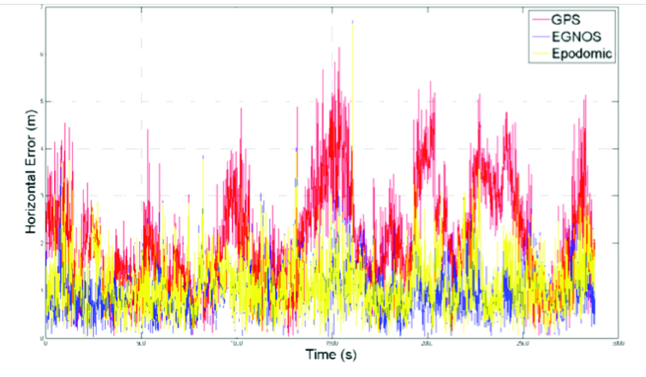
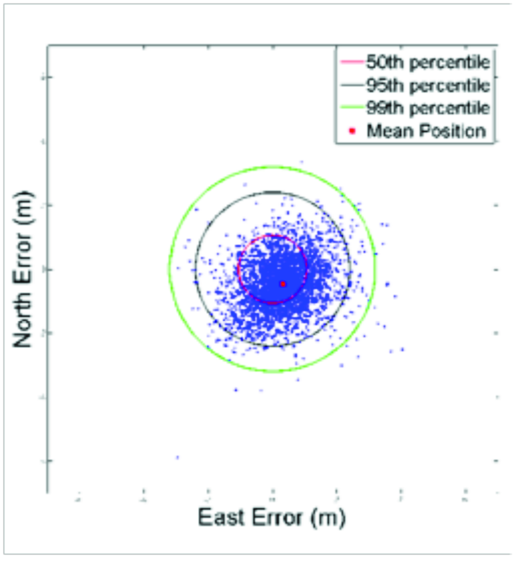
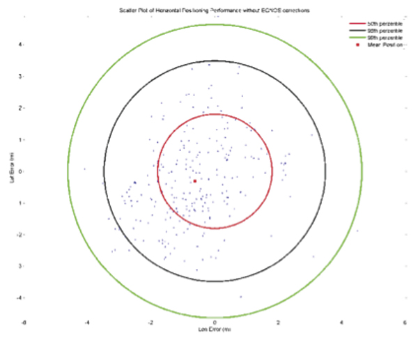
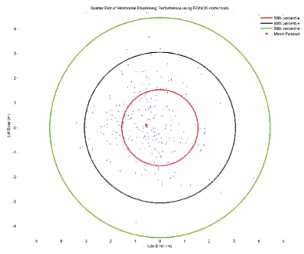
    EGNOS improves accuracy and provides integrity to the GPS signal over most of Europe and parts of North Africa. The system uses a monitoring network of 40 ground stations to provide the corrections with 99.9 percent availability over the core service region. Accuracy is measured by GPS user equivalent range error typically about 4.2 meters after EGNOS corrections for GPS signals from satellites at a 5-degree elevation, and 2.4 meters for satellite signals arriving from a 90-degree elevation. If reliability falls below a minimum level, EGNOS users are alerted within six seconds.


    Russian SBAS Satellite Passes Transponder Tests

    The Luch-5A geostationary communication satellite under construction has successfully completed a cycle of transponder tests. The satellite includes a transponder for the System for Differential Correction and Monitoring (SDCM), the Russian satellite-based augmentation system. SDCM will provide integrity monitoring of
    GPS and GLONASS satellites and differential corrections and analyses of GLONASS performance: real-time differential corrections with horizontal accuracy of 1–1.5 meters, vertical of 2–3 meters.

  • EGNOS Gets to Work

    EGNOS Gets to Work

    Using the Augmentation System with GPS-Equipped Mobile Phones

    By François Boullete, Boris Kennes, Michaël Mastier, and Lee Banfield

    GPS corrections from the European Geostationary Navigation Overlay Service can improve the positioning accuracy and user experience of GPS-enabled mobile phones, even if EGNOS satellites are not visible and even when the GNSS chipset in the phone does not support satellite-based augmentation systems.

    Today, more than 20 percent of mobile phones in use in Europe include a GNSS chipset, and the penetration is expected to exceed 50 percent in the next 5 years. Despite its success in other sectors such as agriculture since the launch of its Open Service in October 2009,

    EGNOS has received limited adoption in location-based services (LBS) and consumer applications, due to two main obstacles. First, the signals from the three EGNOS geostationary satellites that are easily received in open-sky environments are difficult to receive in cities, due to masking by buildings. Second, most GNSS chipsets embedded in today’s mobile phones are GPS-only without SBAS support, or use SBAS for ranging only, a function not supported by EGNOS at this stage.

    The European GNSS Agency (GSA) and the European Commission (EC) supported the work described here to provide mobile phone operating system and application developers with a library of functions to allow them to benefit from EGNOS in all their applications. It works by receiving correction data via mobile communication networks when EGNOS satellites are not visible to the user device and even when using a standard GPS chipset, overcoming these two main obstacles for adoption.

    Targeted mobile operating systems now include Nokia Maemo, Google Android, and Microsoft WinMobile. Further work will extend to this list to other compatible platforms.

    This article demonstrates the feasibility and shows the performance of a software-based EGNOS solution and seeks to create awareness among mobile operating system and application developers on EGNOS.

    User Benefits and Constraints

    Although the sources of GPS positioning errors in urban areas are mainly due to multipath and GPS satellites availability, SBAS corrections on GPS satellites clocks and orbits and ionospheric correction model can still add value in case of moderate multipath environment characteristics. Although GPS stand-alone accuracy is nowadays generally sufficient, it is expected to degrade in the next couple of years as solar activity increases. Availability of free EGNOS corrections delivered via the mobile communication network will help maintain accuracy during these high solar activity periods.

    The limited visibility of EGNOS satellites in urban areas requires the use of the mobile communication network to retrieve the EGNOS corrections. This can be perceived at the first sight as a drawback to the proposed solution as it involves communication costs. However, the required bandwidth is negligible compared to today’s mobile applications such as music and video streaming; further, mobile operators increasingly offer smartphones with unlimited data-access packages.

    Implementation Overview

    Implementation of EGNOS in current-generation mobile phones requires the introduction of a new library of functions at the software level that will allow application developers to get the best possible accuracy in their application regardless of the underlying algorithms used for position calculation. Such a library of functions can eventually be integrated directly in the application programming interface (API) of the phone operation system. At this point, application developers will simply request a position using the API, and the API will return the EGNOS improved position.

    The main computations performed by this EGNOS library (see Figure 1) can be summarized as:

    • Reception: the GPS user position, satellites used, and their elevations and azimuths in NMEA format are requested to the phone’s GPS chipset, and the EGNOS correction message and Klobuchar ionospheric model parameters are received from a distant server (for example, EGNOS Data Access Service EDAS) using the communication link available at the mobile phone;
    • Preparation: collected input data are decoded and prepared for next step;
    • Calculation: the new position corrected by EGNOS is calculated by re-creating the line-of-sight or design matrix (using user position and satellite geometry), applying the EGNOS fast, long-term (including clock), and ionospheric corrections (included in the EGNOS message) and subtracting the Klobuchar ionospheric correction that was (assumed to be) applied at chipset level;
    • Output: the EGNOS corrected position is encoded in NMEA format and returned to the application.
    Figure-2
    Figure 1. Overview of EGNOS library implementation.

    Data Access via the Internet

    The EGNOS correction message and Klobuchar ionospheric model parameters are requested by the mobile phone to a distant server. Although the parameters and ephemeris data are stored on the phone’s GPS chipset once it has decoded the messages from GPS satellites, this data is not made available to other phone applications, hence the need to recover it from a remote source. Today, two alternative servers are available: the EGNOS Data Access Server (EDAS) developed by the EC and Signal-in-Space through the Internet (SISNeT) developed by the European Space Agency (ESA).

    SISNeT’s advantage is the simplicity of the message (hundreds of bits per second) and the availability of specific functions that allow requesting all the necessary data for our application. However, SISNeT messages are produced from EGNOS signals in space, not from the ground segment: an EGNOS receiver installed at ESA’s ESTEC center receives the signals, demodulates them, extracts the correction message, and re-broadcasts it via the Internet. The reliability and availability of this approach depend upon the good reception of EGNOS signals at this site. Interference or EGNOS broadcast failure could disrupt service.

    Unlike SISNeT, EDAS takes the EGNOS correction message directly from the EGNOS system, which guarantees higher service reliability and availability. Nevertheless, the EDAS message is complex and contains much more than the data required for the present application (hundreds of kilobits per second). Therefore a direct connection to EDAS would be inadequate. As a result an EDAS proxy needs to be interfaced between the EDAS server and the mobile platform in order to filter the data flow and extract only the required data. This proxy provides the same kind of messages and functions as SISNeT, whose specifications are ideal for such an application, however it is using data directly from the EGNOS system and not from EGNOS signals in space, improving reliability. In addition, planned EDAS improvements include the provision of such a simplified service directly from the server, removing the need for a proxy.

    Independently of the data server used, the mobile platform must retrieve the EGNOS correction messages, and the Klobuchar ionospheric model parameters. The correction message is composed of a number of different message types (MT) as defined in the SBAS standard established by the International Civil Aviation Organization. For our application, the most important messages are:

    • MT1, the PRN mask that shows to which satellites (PRN) the data contained in the other, subsequent messages are related;
    • MT2-5, containing data to correct rapid variations in the ephemeris and clock errors of the GPS satellites. The important bits for us in these messages are the fast corrections for each satellite used to calculate the user position;
    • MT25, with data to correct long-term vari
      ations in the ephemeris errors and clock errors of the GPS satellites;
    • MT18, the ionospheric grid points (IGP) mask that associates ionospheric corrections in MT26 with the IGPs to which they relate;
    • MT26, providing data to compute the ionospheric corrections for the IGPs present in the IGP mask. In particular it contains the grid ionospheric vertical delay.

    The eight Klobuchar ionospheric model parameters must also be obtained from the distant server (using, for example, the GPS_IONO request with SISNeT).

    Corrections from GNSS Chipset

    The correction algorithm on the phone takes the original position provided by GNSS chipset and identifies the GPS satellite measurements which were used in this computation. It then determines a pseudorange correction for each of the GPS satellites used, and using knowledge of the user-satellite geometry, translates these to a combined position-domain correction.

    Most mobile phones’ operating systems allow access to the NMEA sentences from the GNSS chipset using native API functions, for example, onNmeaReceived() with Google’s Android. In order to apply the EGNOS correction algorithms developed in this paper, the minimum required NMEA sentences are GGA, GSA, and GSV.

    To construct pseudorange corrections, the Design matrix containing of line-of-sight vectors to the satellites is reconstructed using the elevation and azimuth data. All EGNOS corrections for the satellite orbit and clock errors and the ionospheric delay are applied in this range domain. The algorithm assumes that the Klobuchar model will have been applied to correct for the ionospheric delay in the original GNSS chipset positioning solution. Therefore it provides an adjustment to this original correction to exploit the greater accuracy of the EGNOS ionospheric data. Finally these range corrections are propagated into the position domain using the Design matrix. This provides a 3-dimensional position shift to apply to the original chipset position.

    Implementation with Google’s Android

    To obtain NMEA strings from an Android phone requires the ‘onNmeaReceived’ function, a function of the LocationManager class. The LocationManager uses the function ‘requestLocationUpdates’ to get a continuous update of the position input, which in this case is GPS. To implement the LocationManager, a LocationListener must be implemented either by the current activity or as a variable. The ‘onNmeaRecieved’ function will be called every second from the instant the Android’s GPS is switched on. The function provides the NMEA strings with a timestamp using the phone internal clock. This timestamp is not derived from GPS and should be used only for logging.

    The HTC Legend produces the $GPGSV, $GPGGA and $GPGSA messages that are needed for the application. The Legend also produces $GPRMC and $GPVTG strings. The $GPGSV provides the elevations and azimuths needed for the algorithm, the $GPGGA provides the time, original position and number of satellites in the fix and the $GPGSA provide the PRN numbers of the satellites used in the fix.

    For the present testing, necessary data are received via a TCP/IP connection to the SISNeT server (the EDAS proxy server described previously can be used in exactly the same way). For a snapshot solution a continuous connection is not needed and all the information is collected via ‘GETMSG’ and ‘GPS_IONO’ calls. ‘GETMSG’ calls get the last of a specific message type going back up to 30 messages. The types 0,1,2,3,4,5,18,24 and 26 were needed to provide the information for the position domain correction matrices. Only the last message types 0,1,2,3,3,4,5 were needed with type 18 needing 4 and many more of type 24 and 26.

    The ‘GPS_IONO’ message gets the current Klobuchar values. By asking for all of the specific message types, almost instantly all the information is gained without having to wait for the 3 minutes Ionospheric grid cycle (message types 18 and 26) and the variable speed, dependant on number of satellites, complete slow correction set. Once the data has been downloaded from the server the connection is closed.

    A streamed input could be used with the above approach by continuing to receive data after the initial connection and not closing the connection until the application using the service requested. This would require a continuous stable connection to a high speed mobile network and a limited use of the internet from other applications. As mobile technology improves this will not be a problem but is difficult to achieve with GPRS and 3G networks at present.

    Figure 2 shows the current application running on the HTC Legend phone with corrected positions displayed alongside the original GPS positions.

    Figure-1
    Figure 2. Application running on HTC Phone.

    Test Results

    Before testing the implementation of the concept on a mobile platform, some initial tests were performed on an offline basis in order to assess the impact of the position correction and verify the approach. This was achieved through the use of 30s data recorded at continuously operating IGS reference stations, freely available over the internet. The data was processed using an in-house PVT engine designed to be representative of LBS implementations, in order to produce stand-alone and conventional EGNOS solutions. The algorithm described in this paper was then applied to the stand-alone solutions, after downloading EGNOS data from ESA’s EGNOS Message Server (EMS) which allows access to past broadcast messages, to produce a third set of solutions. The accuracy of each solution set was then computed based on the precise coordinates of the reference station made available by the IGS. Whilst this approach replicates the mobile phone correction algorithm it should be noted that there is less uncertainty involved in this offline approach as we can ensure that the assumptions made regarding the original PVT solution are valid. We must assume that the phone chipset PVT is a snapshot solution (no filtering) using the Klobuchar ionospheric model and an elevation-dependent weighting scheme.

    The plots from Figures 3, 4, and 5 show the errors in position estimates obtained from a 24-hour dataset recorded at the HUEG IGS station in Huegelheim, Germany on May 5, 2010. Table 1 shows the statistics associated with the figures.

    Figure-3
    Figure 3. Stand-alone GPS horizontal positioning performance over 24 hours at HUEG IGS station.
    Figure-4
    Figure 4. Conventional EGNOS horizontal positioning performance over 24 hours at HUEG IGS station.
    Figure 5. Position domain EGNOS horizontal positioning performance over 24 hours at HUEG IGS station.
    Figure 5. Position domain EGNOS horizontal positioning performance over 24 hours at HUEG IGS station.
    Bou-T1
    TABLE 1. Horizontal positioning performance statistics from 24hr HUEG IGS station analysis.

    The results demonstrate that the conventional EGNOS solution improves the horizontal positioning performance of GPS, with an improvement in the 95th percentile of around 2 meters in this example. Importantly, it can be seen that the position domain EGNOS algorithm achieves a similar level of performance to conventional EGNOS. This can be seen more clearly by comparing the instantaneous horizontal error over this period from the three alternative solutions, as shown in Figure 6. It is clear that the position-domain EGNOS correction shown in yellow reduces the horizontal error of the GPS solution (red) in a similar way to conventional EGNOS (blue).

    Figure 6. Time series of horizontal positioning errors for stand-alone GPS, conventional EGNOS, and position domain EGNOS solutions at HUEG IGS station.
    Figure 6. Time series of horizontal positioning errors for stand-alone GPS, conventional EGNOS, and position domain EGNOS solutions at HUEG IGS station.

    Similar behavior was found in other datasets tested. With the ability of the algorithm to replicate conventional EGNOS performance verified, we assessed the performance when integrated on an HTC Legend phone. The key differences here were the real-time connection to the EGNOS data server and the uncertainty in the assumptions made regarding the chipset positioning algorithm.

    Testing began by assessing the performance of the application over a static point. Two precisely surveyed points were used for this purpose at four separate time periods. The test method simply involved holding the phone over the point (vertical accuracy was not assessed) and requesting a corrected solution from the application, along with the original GPS chipset solution. The chipset applies stand-still detection to avoid generating multiple GPS positions for a single user location which would be unnecessary in typical phone applications. To generate a sample of position estimates therefore the phone was repeatedly moved away from the reference point then returned to it over the test period. This makes the collection of very large datasets over extended periods impractical. The samples from the four test periods were combined in order to generate results with greater statistical significance. 261 samples were collected to produce the results shown in Figures 7 and 8, and the statistics in Table 2.

     Figure 7. Stand-Alone GPS Horizontal Positioning Performance from online static point testing.
    Figure 7. Stand-Alone GPS Horizontal Positioning Performance from online static point testing.


    Figure 8. Position Domain EGNOS Horizontal Positioning Performance from online static point testing.
    Figure 8. Position Domain EGNOS Horizontal Positioning Performance from online static point testing.
    Bou-T2,png
    TABLE 2. Horizontal Positioning Performance from online static point tests.

    The results indicate a small improvement in horizontal accuracy as a result of the position domain EGNOS correction. The statistical significance of these results is perhaps questionable given the limitations of the test method and relative small sample size. The reduced level of improvement compared to the offline tests is thought to be due to imperfect assumptions made about the chipset positioning algorithm. The correction algorithm must make many assumptions about the way in which the original GPS position has been computed by the phone chipset. These include assumptions on the measurement weightings used, an assumption that a filtered solution is not applied, assumptions that no additional sensors or systems (accelerometers, digital compass or cellular positioning) influence the computed position, and also assumptions that all information reported in the NMEA strings is accurate. Further work seeks to determine if the algorithm can be improved to better replicate the processes applied in the initial GPS solution in order to make a more significant improvement.

    The phone GPS positioning achieves similar levels of accuracy to processing single-frequency data collected at an IGS station. This level of accuracy would be more than adequate for most LBS applications in which the main requirement is to be able to reliably relate a user location to a map or imagery feature. With increasing solar activity over the next few years, leading to larger ionospheric delays on satellite signals, the performance of standard GPS solutions will degrade, making the benefits of the more accurate and timely EGNOS corrections more significant.

    Conclusions and Way Forward

    By a relatively simple translation method, EGNOS data may be mapped into the position domain, allowing a user position solution to be corrected for signal-in-space (satellite orbit and clock) and ionospheric errors detected and predicted by EGNOS. User position solution provided by the phone chipset may be corrected in near-real time based on data downloaded from a distant server.

    The method replicates conventional EGNOS performance (corrections applied at the pseudorange level) when all assumptions regarding the stand-alone GPS user position are valid. Ongoing work seeks to determine if the correction algorithm can be enhanced to provide a greater level of improvement to GPS positions on the phone platform. Ideally, it should be able to provide improvements similar to those produced when EGNOS data is applied in a conventional manner in the position solution. Developers would need to judge the significance of any potential improvement for their intended application.

    The EC has launched a project to port this EGNOS library to other mobile platforms and complement it with additional functions that are needed by the application developers and that can bring user benefits. The software library can be obtained free upon request to [email protected].

    Acknowledgments

    Special thanks to Nottingham Scientific Ltd. for its work on this topic and cooperation in preparing this paper. This article is based on a paper presented at ION-GNSS 2010.


    François Boullete was market development officer at the European GNSS Agency at the time of this work. He holds a diploma in project management from HEC and a diploma in engineering from Ecole Centrale.

    Boris Kennes is R&D and market monitoring officer at the European GNSS Agency. He has a background in engineering and strategy consulting.

    Michaël Mastier is policy officer at the European Commission in the Galileo/EGNOS applications unit. He has an engineering education and diploma in public works from ENTPE in Lyon, and a computer science post-graduate diploma from Saint-Etienne University, France.

    Lee Banfield is a software engineer at Nottingham Scientific Limited (NSL) in the UK. He has developed applications which use EDAS data to provide EGNOS corrections, GNSS assistance messages and GNSS performance metrics for a range of road and LBS applications.

  • Webinar Follow-up Q&A: SBAS, DGPS or Post-Processing? Which Should You Use?

    Last week, I conducted a webinar along with Dr. Michael Whitehead titled “SBAS, DGPS or Post-processing? Which Should You Use?” It was one of the best webinars I’ve conducted to date. More than 600 people registered. We barely squeezed it into 65 minutes and could have kept going for the better part of two to three hours, given the subject matter to cover and the number of questions we received before and during the webinar. Thank you for attending, if you did. If you weren’t able to you, can download it by registering here. After registering, you’ll be provided a link to download it.

    I knew that only having 65 minutes would be a serious issue for the webinar because the discussion could take many worthwhile tangents. And it was. But alas, we stuck to the presentation agenda, stayed on schedule, and were able to address several audience questions.

    We had a lot of questions before and during the webinar. As customary, I’d like to address some of those as well as present the poll results here. First, the poll questions and results with accompanying pie charts to illustrate the results.


    Poll #1: For those of you who use post-processing, what are the reasons you use it?

    Total votes: 117

    Gakstatter comment: This is an interesting spread with no clear dominating reason. Based on data I’ve seen and data we collected, I’m not convinced that post-processing is more accurate. If it is, is it worth the extra 10%, 20%, or ??% accuracy? I understand the votes for more reliable corrections. There’s something to say for reverse processing (forwards and backwards).


    Poll #2: For those of you using post-processing, from where do you access GPS base station data?

    Total votes: 129


    Gakstatter comment: These answers don’t surprise me. National and regional CORS have become very prolific in the past 10 years.


    Poll #3: For those of you who use real-time DGPS/SBAS, what is the reason you use it?


    Total votes: 110

    Gakstatter comment: These answers surprised me a little. I thought more people would vote for “less complicated.” Does that percentage of users really need corrected coordinates in the field? Why? E-mail me a quick answer if you have a chance.

    Poll #4: For those of you using real-time DGPS/SBAS, from where do you access DGPS/SBAS corrections?

    Total votes: 129

    Gakstatter comment: This answer doesn’t surprise me at all. I suspect RTK networks will increase due to their continued proliferation and different levels of accuracy offered.

    Poll #5: When I purchase GPS/GNSS equipment in the future, I will likely select equipment that utilizes the following correction method (select all that apply):

    Total votes: 144

    Gakstatter comment: This was the only multi-answer poll. People could select more than one answer. These answers were surprisingly close. That surprised me. It didn’t surprise me that SBAS was the leader. It surprised me that post-processing is still as predominant as it is. If you have a chance, e-mail me a quick explanation as to why you will use post-processing in the future.

    Before diving into some audience questions, I’d like to clarify the slide illustrating the post-processing plot shown below.

    During the webinar, we were discussing PPP (precise-point positioning) when this slide was displayed. This data was not corrected via PPP, but rather post-processing the pseudorange data, which is the equivalent of L1 SBAS and L1 DGPS. The point was to show how SBAS/DGPS accuracy compares to post-processing. In the real world, you won’t post-process 24 hours of data. Some of you will post-process only a few minutes of data per session in cases where you need to turn off the receiver and travel between points. In other cases, users will keep the receiver tracking between points, allowing reverse processing to work more effectively.

    On to the Questions


    Question #1: Will there ever be a way in which the position of a rover can become fixed by using two fixed base stations?

    Gakstatter comment: SBAS does this already. SBAS’s consist of a number of base stations within the coverage area (e.g., WAAS has 38). Data from many base stations is used to compute the correction information sent to an SBAS-enabled GPS receiver.

    I’m assuming your reasoning is to improve position integrity.

    Another method of accomplishing this is by post-processing against more than one base station or switching between DGPS beacon stations. If they differ significantly, then you might want to compare against a third base station.
    Question #2: At what point in time will the strength of the GPS signal be increased? To what strength will this occur? 500 times more powerful? What improvements in signal reception will be experienced? Indoor my house reception?
    Gakstatter comment: The GPS broadcast strength is increased with new GPS satellite model. For example, the current Block IIF satellite broadcasts the new L5 signal about four times stronger than L2C. While no one can be sure yet as to how much this will improve indoor positioning, there will be some marginal improvement in conditions where GPS doesn’t operate very well today. Also helping will be the improved code and error-correcting techniques that should make operating in difficult conditions a bit better, especially where there are a mixture of satellites with strong and weak signals.
    Also, it raises the issue of a viable L5 single frequency receiver, which should outperform the L1 C/A single frequency receivers of today.
    Question #3: NAD83, WGS84, ITRF differences, how to make the best choice?
    &nbsp
    ;
    Gakstatter Comment: I don’t think there is an incorrect choice, except maybe that NAD83 is a 2D system and will eventually give way to a 3D system, but that won’t happen in the U.S. for many years.
    Otherwise, it’s a question of matching disparate data sets. Probably the #1 question I hear from users is “why doesn’t my GPS data line up with my basemap?” The answer is almost always a difference in datums. Many papers have been written on this. Click here for a good PowerPoint presentation created by Dave Doyle of the National Geodetic Survey.
    Question #4: Are there any open source post-processing software programs available?
    Gakstatter Comment: Mike suggested looking here….http://gpspp.sakura.ne.jp/rtklib/rtklib.htm
    Question #5: If a person uses real-time correction satellites, is there a need to post-process?
    Gakstatter Comment: It’s rare that someone would do both, but not out of the question. For example, one might rely primarily on real-time corrections and record raw data for post-processing in case there is a problem receiving the real-time corrections. The opposite is true, too. One might rely primarily on post-processing and use real-time corrections as a back-up in case there is a problem with post-processing.
    Caveat emptor: There are probably datum differences between the sources of real-time and post-processing corrections. This needs to be reconciled when combining data that has used the two sources.
    Question #6: Is it possible to post-process data without using a DGPS?
    Gakstatter Comment: Yes, all that is required for post-processing is the ability to record raw observation data.
    Question #7: Are there geographic areas in the U.S. that are not covered by NGS CORS stations?
    Gakstatter Comment: No, not for pseudorange (L1) differential corrections. The distance to the base station will vary depending on where you are located and thus may affect your accuracy to some degree, but the density of CORS in the U.S. is such that you will never be more than a couple of hundred kilometers from a base station and likely much closer.
    A side note: Back in the mid-1990s, I remember experimenting with post-processing software we were developing. At that time, I tried post-processing data collected in Oregon with a base station located in Atlanta, Georgia. This was a 2,500 km baseline. It produced a result, albeit not one I would necessarily trust. The only limitation is that the two units must track common GPS satellites. With that length of baseline, it’s possible that only half of the satellites tracked may be in common.
    Question #8: What is the ideal distance range from a CORS station to your site to use post-processing?
    Gakstatter Comment: Ideally, as close as possible. The further you are from a base station, the more potential error will be introduced due to atmospheric differences between the two locations. As stated above, the density of CORS (at least in the U.S. and many parts of the world) are such that the nearest base station is quite near and likely no more than a couple of hundred kilometers away.
    Question #9: What is the trade-off between short observation time (couple of minutes) to position accuracy when using post-processing?
    Gakstatter Comment: Ok, remember we are talking about pseudorange corrections (as opposed to carrier phase). Given that the receiver has been tracking satellites for a period of time (let’s say two minutes), the observation times only need to be a few seconds for each feature to be mapped.
    For example, if you are mapping utility poles and don’t turn off the receiver between poles, you only need a few seconds (5-10 seconds) of data for each pole and average it for the final coordinate. Think about if you’re mapping a road centerline. You’ll likely record data while moving, so each second you are recording a new position.
    Question #10: What about the vertical correction? I see in the slide an antenna carried in a backpack. Is the antenna placed at ground level for point? Is there a constant correction required?
    Gakstatter Comment: Vertical accuracy is typically worse than horizontal accuracy by a factor of 1.5-2.0 due to the inferior satellite geometry, especially in areas of hilly terrain and/or trees/buildings where the horizon is blocked. Good geometry for vertical positioning requires tracking a number of GPS satellites that are low on the horizon.
    Question #11: What is the future of DGPS? I heard Coast Guard beacons were going away?
    Gakstatter Comment: The beacon stations operated by the U.S. Coast Guard are not in jeopardy and never have been. Neither have the marine beacons in the other 40+ countries that broadcast GPS corrections. However, the U.S. Department of Transportation operates 29 inland stations in the U.S. which have faced budget challenges the past few years. In April 2008, the U.S. DOT issued a policy decision to continue operating the 29 inland sites. Construction of seven sites remains that would allow the Nationwide DGPS to reach Initial Operating Capability (IOC), which would provide coverage to 99% of the continental U.S. No budget has been approved for the construction of those seven sites.


    Question #12: Can you briefly explain the difference between DGPS & RTK?
    Gakstatter comment: Here are a couple of good websites that explain each of these techniques. Essentially, DGPS is a real-time GPS positioning technique accurate to about 30 centimeters at the very best. RTK is a real-time GPS positioning technique accurate to about 1 centimeter.
    Question #13: How much time do you need to get the position from the base station for real-time DGPS?
    Gakstatter comment: Assuming both receivers are already tracking satellites, your receivers will begin using the base-station corrections as soon as the data link is made between the two.
    Question #14: Can you comment on advantages (if any) of using corrections from a network RTK service for DGPS corrections. Any advantages on eliminating base separation?
    Gakstatter comment: I’ve heard that DGPS corrections are optimized within an RTK Network. However, I need to research this a bit further to better understand the true advantages, if any.
    Whitehead Comment: A virtual base station (VBS) solution could be formed using the network. Thus differential GPS could exhibit the same advantages using such a network that RTK does (cancellation of atmosphere errors). The software would have to support this.
    Note though that if close to one of the Reference Stations in the network, it is probably best to just use the nearest Reference station as this will best cancel the atmosphere errors. When in the middle the network, the VBS solution would use surrounding reference stations to provide a good approximation of atmospheric errors and then output a correction that looked like it originated from a reference station (virtual station ) near to the users receiver.
    Question #15: What is up with PRN 135? Still on station?
    Gakstatter comment: Communication has be re-established with WAAS PRN 135 and is being tested by its owner, Intelsat, as well as the Federal Aviation Administration (FAA). See a detailed article by clicking here. The latest information I heard is that it’s currently at 93°W longitude undergoing testing. If the testing is successful, it will be re-located back to 133°W longitude and brought back into WAAS service. A timeline has not been published, but I’m guessing within the next 30-60 days.
    Question #16: We used to hear that your point accuracy degraded as the distance from the base station increased. One reason we used to post process. Is this still a factor?
    Gakstatter Comment: Due to advancements in GPS technology, it’s not as much of an issue as it used to be. I think this is illustrated in the results we achieved in our 24 hr test data.
    Ten years ago, it would be hard to find a GPS L1 receiver that would receive DGPS corrections from a beacon station 184km away and still achieve sub-meter horizontal accuracy at the 95% confidence level.
    I’m not saying the distance is negligible. There still the issue of tropospheric, ionospheric and satellite orbit errors as you move farther away from the base station. But, it’s certainly less of a factor than it was before.
    Whitehead Comment:
    Question #17: If we use WAAS correction, does it really help to try to use a post-processing type of software afterward? So far we just use WAAS correction.
    Gakstatter Comment: One of the reasons we collected data using several sources of real-time corrections and also showed the results of post-processing was to illustrate the differences between the two.
    If you follow proper procedures, there’s no reason to think that accuracy obtained using WAAS will differ significantly from accuracy obtained using post-processing. This is assuming that you’re using a single-frequency GPS receiver and post-processing using pseudorange corrections and not carrier-phase processing. Some receivers like the Trimble GeoXH are actually dual-frequency receivers and so data from it will likely surpass the accuracy of WAAS if you’re using its dual-frequency antenna and equivalent post-processing software.
    By proper WAAS procedures, I mean letting it track for five minutes upon initial start-up to allow it to download a current ionospheric map.
    Question #18: Does SBAS use 1 receiver and no base station? Expensive?
    Gakstatter Comment: SBAS uses 1 receiver and a lot of base stations. You just don’t have to pay for the SBAS base stations (or to use them.) The signal, like GPS, is provided free of charge.
    SBAS consists of a network of base stations (WAAS has 38) and communications satellites that broadcast corrections to users on the ground (or aviation users in the air).
    Question #19: How far north in Alberta is WAAS coverage available and useful?
    Gakstatter Comment: The primary concern would be visibility of the WAAS GEO satellite that broadcasts the correction data. Following is a map that illustrates the coverage. The contour lines are degrees above the horizon for which the two WAAS GEO satellites are visible.
    Solid line = PRN 138, Dashed line = PRN 133
    Question #20: Do you have any comments about CDGPS in Canada/US?
    Gakstatter comment: Sadly, the CDGPS service is being decommissioned March 31. You can read about it here. 
    Question #21: I am hearing from my state specialists (NRCS) regarding the LightSquared issue. We are advising working through the PNT ExComm and our cooperating partners.
    Gakstatter comment: This is a potentially serious issue for GPS users. Click here for the latest news as of February 1.
    Question #22: Where do you find the DGPS beacon station list and what is available to you?
    Gakstatter comment: I’m not sure if this is 100% complete, but it’s the most complete list I’ve seen. Click here.
    Question #23: Are most mapping-grade GPS receivers (for example Trimble GeoXh) equipped off the shelf to receive beacon signals?
    Gakstatter comment: Some receivers are equipped off-the-shelf, others are not (such as the GeoXH) and require additional hardware.
    Question #24: In which areas is it possible to use corrections from OmniSTAR?
    Gakstatter comment: Click here to view worldwide maps of OmniSTAR coverage.
    Question #25: Was the Garmin set to WAAS?
    Gakstatter comment: Yes, during the 24-hour data collection session, the Garmin unit was receiving WAAS 100% of the time as far as we could tell. The purpose of the 24-hour test period was to able to randomly sample data during that period to arrive at the accuracy statistics we presented. I randomly sampled the dataset several time
    s (averaging 10 seconds worth of positions 200 times) and the results were consistent with what we presented.
    Question #26: How does post processing account for ionosphere or troposphere errors if receiver is geographically far away from the base station? If not, does DGPS and WAAS provide better accuracy and integrity?
    Whitehead comment: Post Processing using a CORS station would take the nearest station and do differential GPS which cancels common errors in ionosphere and troposphere (ionosphere and troposphere are both temporally and spatially correlated) so if the CORS station is close, there will be good cancellation. If the receiver is far, the algorithms could use a troposphere model to account for the differential troposphere (as was done in the Presentation for BeaconT) and this would probably cancel troposphere so that remaining errors were sub-decimeter level. Differential Ionosphere errors could also be easily modeled with good results. It is likely that the performance could be made to easily surpass SBAS.
    DGPS would suffer from the same effects as does post processing, and maybe even more so since a model of differential atmosphere errors is rarely used. SBAS will likely provide better accuracy in situations where you are far from a base station.
    Question #27: What is Beacon T?
    Gakstatter Comment: While collecting data to present at the webinar, Mike noticed there was a bias in the beacon measurements. The beacon station is located ~184km away at about 7,000 ft elevation while the test site was at about 1,000 ft elevation. Initially, Mike wasn’t modeling the troposphere difference between the base and rover.
    To model the troposphere, Mike said he used a troposphere model to figure out troposphere in both locations, and then subtract the two. Although the models are not necessarily that accurate in an absolute sense, the differential tropo between the two locations is fairly accurate using the models. This differential tropo allows the receiver to correct the tropo in the base station differential to make it appear as if it originated in the rover location. Mike said he could’ve done the same for the ionosphere, but he didn’t since that is it usually less of a factor. After using the modified tropo model (Beacon T), the height bias was around 1/2 meter, which could be attributable the ionosphere. The horizontal bias is small, as you can see in the results.
    Using this troposphere model resulted in a significant improvement over the original solution.
    Question #28: Why is VBS better than WAAS?
    Gakstatter Comment: It surprised me too. The receiver used was the same that was used for beacon and WAAS. I contacted OmniSTAR for their opinion.
    John Pointon of OmniSTAR responds: “There have been incremental improvements in the VBS service over the years, mostly improvements in modeling and processing. We have added two or three extra reference stations but that hasn’t been the most critical improvement, just helped in some specific areas. These, combined with the relatively benign solar environment, result in VBS accuracy which, although not equivalent to our dual-frequency and multi-system solutions, is consistently better than either Beacon or WAAS.”
    Whitehead Comment: In the past, we’ve seen similar performance from both OmniStar VBS and WAAS.  Different atmosphere conditions and different locations can affect the performance of both. We’ve seen situations where WAAS is better.  It is probably fair to say that OmniStar is more focused on accuracy, whereas WAAS is focused on integrity.  It may be wise to do a comparison in the particular area where you operate.  Note, however, that in the US, OmniStar is referenced to NAD83 whereas WAAS is references to ITRF so positions reports between the two can differ by several meters.
    Question #29: When I look at your scatter plot, I have to ask if short-term point averaging is really effective at achieving more accurate positions?
    Gakstatter Comment: I think it’s well accepted that you are wasting time by occupying a point for 180 seconds. That said, there’s something to be said for letting the receiver track satellites for a period of time (1-2 minutes) before storing 5-10 seconds of data. Of course, if the receiver is already tracking satellites, then it’s not necessary to wait. The idea is to let the measurements settle down and take advantage of carrier-phase smoothing if the receiver uses that technique.

    Question #30: Could you go into PPP a bit more? How does it work?

    Gakstatter Comment: We opened a can of worms by discussing PPP. It’s an entirely different subject that I will cover in a future article. In the meantime, you can read Dr. Richard Langley’s article on PPP here.

    Question #31: How do you test the accuracy of SBAS collected data?

    Gakstatter Comment: In the U.S., it’s easy. Find a local survey mark using the National Geodetic Survey website. Printout the ITRF coordinates of the survey mark. If they aren’t on the datasheet, you can convert from NAD83/CORS96 to ITRF using the HTDP program. Compare the coordinates output by your GPS receiver to the coordinates of the survey mark.
    If you’re located outside of the U.S., look for a similar government agency in your country that maintains a record of survey marks. It’s vital that you are comparing coordinates referenced to the same datums.


    Question #32: Will there be any disadvantage if we use a EGNOS corrections in Kuwait, if we receive EGNOS?

    Whitehead Comment: Kuwait is outside the EGNOS coverage zone, so satellites to the south may not even have Clock and Orbit correctors available, which means the Receiver could not compute a correction for these satellites.  Unless the receiver can mix differentially cor
    rected ranges with non-differentially corrected ranges, it would likely drop the satellites in the south that had no corrections. This would then reduce PDOP and thus accuracy. Mixing differentially corrected ranges with non-differentially corrected ranges may give worse accuracy than no corrections at all since the SBAS system may have clock or other biases relative to GPS.
    By the way, I wish the SBAS providers would get together and share data so that they each could provide world-wide orbits and clocks. Then it would matter less if you were outside the coverage area.
    Gakstatter Comment: I’ve heard that EGNOS is planning an expansion to the south and east, so Kuwai may eventually be within the EGNOS coverage footprint. Also, you’ll want to monitor the progress of India’s GAGAN system, which is a similar SBAS. It’s possible you might fall within the GAGAN extrapolated footprint for non-aviation users.

    We covered most of the questions posed by the audience. If we didn’t address yours or didn’t provide a complete enough answer for you, please e-mail me and I’ll do my best to answer you.
    As I mentioned above, we had quite a few questions about PPP. It’s a technology that’s worthy of further coverage and discussion. Look for a future article on it.
    Thanks, and see you next time.
    Follow me on Twitter at http://twitter.com/GPSGIS_Eric


  • On the Edge: Five Big Ones in Ten


    Look back with me at the five 2010 GNSS events that most affected surveying, mapping, engineering, construction, and natural resource users. Each one had, or could have had, a significant effect on you and your work. Taking it from the top:

    GPS 24+3 Constellation. The most important event occurred a year ago, when the Air Force began implementing a new GPS 24+3 configuration. They had their military reasons, but the benefit for you and me is eliminating GPS brownouts — periods with fewer GPS satellites in view. When combined with obstructions such as terrain, trees, or buildings, they made GPS hard to use.

    It’s especially an issue with real-time kinematic (RTK) high-precision users because RTK technology is satellite-hungry. It needs six or more satellites to provide a robust position solution.

    The Air Force moved three satellites, SVNs 24, 26 and 30, from their original slots. SVNs 26 and 30 have already reached their destinations, and SVN 24 will do so this month.

    Three other satellites are being shifted slightly. SVN 55 found its new slot in December, while SVNs 46 and 56 start this month and should have completed their journeys by May/June 2011.

    By now, you should be seeing some improvements in GPS satellite visibility. Although you’ll see fewer peaks (high number of GPS satellites in view), you’ll also see fewer valleys (low number of GPS satellites in view). This should increase productivity for RTK users and those in obstructed environments such as tree canopy.

    First GPS Block IIF. Although it doesn’t really help users at this point other than being another satellite to enter service, the Block IIF satellite launched in May is the first to broadcast the third civil signal. L5 marks the beginning of a new era in high-precision GPS positioning. The Block IIF launch was the catalyst for my June column “What Happen When High Accuracy is Cheap?”

    This IIF is just a teaser though, and its fellows will launch at a snail’s pace. Remember though, it costs upwards of $200 million to launch a satellite and since there ares already 30+ operational GPS satellites in orbit, it’s hard for Congress and the Air Force to justify speeding up the launch schedule. The last target I heard was to have 24 satellites broadcasting L5 by 2019.

    GLONASS Growth. Despite the recent catastrophe, the Russian Federation was still able to launch seven new satellites in 2010, including a new K1 satellite that will test a new CDMA signal for better compatibility with GPS.With 21 operational satellites and three more coming in March, a consistent and healthy number of GLONASS satellites in orbit has given receiver manufacturers more confidence to develop GPS/GLONASS receivers. This year, we’ve seen several manufacturers integrating GPS/GLONASS into handheld receivers as well as OEM board products.

    User benefits are clear: more robust positioning and improved productivity due to decreased down-time.

    Solar Activity. The big news is no news: the sun was eerily quiet in 2010. If your GPS receiver didn’t work at times this year, it wasn’t due to solar activity. But it may ramp up in 2011.

    GAGAN, WAAS Failures. The Indian Space Research Organisation and the U.S. Federal Aviation Administration received a hard lesson in SBAS GEO management. In April, an Indian rocket launch failed, and one of the FAA WAAS satellites lost communication with its ground control.

    If you’re an SBAS user, don’t let it bring you down. SBAS is here to stay, and likely you were not affected by either incident — unless you work in northwest Alaska. A new U.S. SBAS satellite came online, and India is regrouping for more launches.

    Follow Eric on Twitter at GISGPS_Eric.

  • SBAS (WAAS) and NDGPS Accuracy and Statistics

    There’s something I’ve been wanting to write about since the ION-GNSS conference a few weeks ago. However, a nasty cold, a 10-day trip to Europe (INTERGEO conference), and some jet lag have kept me from it until now.

    Here goes.

    First of all, most of the presentations from the CGSIC meeting are available on the USCG Navigation Center website. You can view them by clicking here. There’s some very good reading and most of it is pretty light-weight and in PDF format.

    One of the presentations at the CGSIC (Civil GPS Service Interface Committee) meeting during the ION-GNSS conference was “Integrating NDGPS and SBAS —
    An Optimal Real-time GPS Mapping Solution,” presented by Jean-Yves Lauture of Geneq, Inc.

    I’m publishing two of the slides from his presentation in order to:

    1. Show the accuracy potential of WAAS and NDGPS given a high performance L1 receiver.
    2. Discuss the statistical names/values used to express GPS accuracy.

    First of all, each of the slides below are at the same scale. Each ellipse is 20 cm with the outside limit (radius) being one meter.

    I’ve known for quite sometime that SBAS (WAAS in this case) is capable of sub-meter precision with a single-frequency GPS receiver. These results are a bit better than what I’ve seen personally, and keep in mind it’s a limited data set of 1,800 continuous epochs, but impressive none the less. Also, keep in mind that the WAAS Performance Analysis Report published quarterly by the FAA’s National Satellite Test Bed shows the 95% horizontal accuracy value for Denver, Colorado, (near where this data was collected) being .547 meters for the quarter ending June 30, 2010 (7,856,354 samples collected over three months).


    30 minutes of WAAS-corrected data (each ellipse represents 20cm)


    The results I didn’t expect were the slide below, which shows NDGPS-corrected results using the same receiver/antenna. Keep in mind this is a GPS L1 receiver using phase-smoothed pseudorange measurements, not a GPS L1/L2 receiver using a carrier-phase float solution. If you look closely, you’ll see it states the baseline distance is 200 km. Granted, this is a limited data set, and I’ll be interested in seeing further results. If this was a dataset presented by a manufacturer or other party with some sort of interest, I wouldn’t publish it, but this is data collected by an objective entity (a credible U.S. government agency) so that earns, in my mind, a level of credibility.

    The results are pretty impressive. All data points fall within ~20 cm.

    30 minutes of NDGPS-corrected data (each ellipse represents 20cm)

    Keep in mind that this data was collected recently, and we are currently in a period of low ionospheric activity. In other words, data was collected under near-ideal conditions. At the end of the day, my point is that GPS L1 accuracy using SBAS and NDGPS has gotten pretty darned good.

    Accuracy Statistics

    The second reason I’m publishing the slides is to discuss accuracy statistics.

    Look at the small box inside each slide showing 99%, 95%, 68%, and 50% accuracies.

    If you look at the data points, it might not be immediately apparent how those values were arrived at. For example, how could a group of data points all within ~20 cm have a 95% confidence of 37 cm?

    To explain this, there was a good article published in GPS World in 2007 titled “GNSS Accuracy: Lies, Damn Lies, and Statistics” by Frank van Diggelen. It does a good job explaining statistical expressions (RMS, 2DRMS, etc.).

    Keep in mind that most manufacturers express horizontal GPS accuracy specifications based on 68% confidence. When the specification sheet states “sub-meter” HRMS (horizontal RMS) precision, that means 68% of the time; the horizontal accuracy will be less than a meter. In reality, that “sub-meter” receiver won’t consistently deliver sub-meter precision. If you convert the 68% HRMS value and express it with 95% confidence (2D HRMS), the actual horizontal precision for that same receiver will be well over one meter. That’s the precision you can expect from the receiver, not the 68% confidence value.

    Thanks, and see you next time.

    Follow me on Twitter at http://twitter.com/GPSGIS_Eric

  • GPS, GLONASS, and SBAS Webinar Follow-up

    Normally, my column following a webinar is dedicated to Q&A follow-up from the webinar. However, immediately following the April 22 webinar, I traveled to Phoenix, Arizona, to attend the ACSM/GITA conference, which I wrote about earlier this month.

    This column is dedicated to answering questions I didn’t address during the webinar. Also, I always find the results from the polls I conduct during the webinar very interesting.

    Poll #1: Have you or your work crews had to stop or alter your work pattern due to the lack of GPS satellites?

    Total votes: 128, Yes: 73%, No: 27%

    Gakstatter comment: This is consistent with other polls I’ve conducted regarding GPS satellite availability. The new GPS 24+3 configuration will help mitigate this problem. Read more about the new GPS 24+3 configuration in a three-part series I wrote earlier this year.


    Poll #2: How often do you upgrade your GPS equipment?

    Total votes: 113

    Gakstatter comment: There’s no clear pattern here except to say that 46% of the users wait until at least 3 years before they consider upgrading their GPS equipment. That makes sense to me.


    Poll #3: Does any of your GNSS equipment utilize GLONASS?

    Total votes: 115, Yes: 39%, No: 61%

    Gakstatter comment: When considering the result of this poll, keep in mind that there are very few “mapping-grade” receivers that are designed to utilize GLONASS. For example, there are very few, if any, sub-meter receivers that utilize GLONASS, primarily due to the lack of correction sources. SBAS doesn’t support GLONASS, DGPS (radiobeacon) doesn’t support GLONASS, and most CORS do not support GLONASS. Only recently did OmniSTAR begin supporting GLONASS. I think this trend will continue, although I doubt that SBAS or DGPS (radiobeacon) will support GLONASS in the foreseeable future.

    Poll #4: Does any of your GNSS equipment utilize SBAS (WAAS/EGNOS/MSAS) as a primary source of corrections?

    Total votes: 111, Yes: 60.5%, No: 39.5%

    Gakstatter comment: This poll result doesn’t surprise me. Given that SBAS corrections are widely available, free of charge, reasonably accurate, and require no action by the user, it makes a lot of sense they are being used.

    Following are some of the questions that were posed by the audience during the webinar:

    Question #1: I am not sure, but when you say you’re “pushing” something out to us, it sounds like your trying to “push” something on us. Just a comment.

    Gakstatter: I’m sorry about the webinar-speak. When I say “pushing the next slide,” that means I’m changing slides. I may change the way I say this. Thanks for your comment.

    Question #2: Can you correct GLONASS signals with WAAS or other real-time technologies?

    Gakstatter: WAAS (or any SBAS) doesn’t support GLONASS. Neither does DGPS (radiobeacon). This doesn’t mean that GLONASS measurement can’t be used, but you’ll be using uncorrected measurements to augment SBAS-corrected measurements. A case where it may be useful is when you’re mapping in an environment where there are a lot of trees. You might only have four GPS satellites visible that are being corrected via SBAS. In that scenario, there might be value in utilizing measurements from GLONASS satellites just to improve the PDOP, even though the GLONASS measurements are uncorrected.

    Question #3: Do you feel manufacturers will begin to release lower-end mapping-grade GPS receivers with L2C and L5 functionality in the future?

    Gakstatter: Yes, I do, but it will be a few years before there are enough satellites broadcasting an L5 signal. I think what you’ll end up seeing are inexpensive L1/L5 receivers (Galileo doesn’t support L2). They will not only be able to provide mapping-grade sub-meter, decimeter) but also RTK accuracies (cm-level). Since L2C and L5 are open civil signals, you won’t see the patent blocks that restrict competition for L1/L2 receivers like you do today.

    I’m not saying L2C will not be supported at all. I think there will be L1/L2C/L5 receivers, but I think you’ll see L1/L5 on lower-end receivers.

    Question #4: There is apparently some degradation of accuracy when using GPS and GLONASS for RTK. Have there been any rigorous studies quantifying this that you are aware of?

    Gakstatter: I’m not sure I’d say I believe there is degradation in accuracy, but I wouldn’t count on GLONASS to improve accuracy. The value of GLONASS is improving productivity. Since it adds several satellite signals to the solution, it effectively eliminates GPS “brown-out” periods so RTK can be used 24/7. There was a rigorous study released by The Survey Association in the UK. The report focused on network RTK. They tested both GPS and GPS+GLONASS. You can download a copy of the report here.

    Question #5: Does using GLONASS-capable receivers shorten the observation time required for fast-static points?

    Gakstatter: My first thought is yes since generally more observables equates to shorter occupation time, but I would check with the manufacturer and follow their recommendations. Honestly, I’ve only used fast-static with GPS-only receivers so I don’t have any personal experience with your scenario.

    Question #6: When is GLONASS-K launch scheduled? When can we receiver a valid CDMA signal?

    Gakstatter: The first GLONASS-K satellite is scheduled for launch later this year. I haven’t seen a launch schedule beyond that. A representative from the Russian Space Agency is scheduled to present at the Institute of Navigation (ION) GNSS conference in September, so I’ll probably learn more at that point. However, it’s a lengthy process. It’s not just a matter of launching satellites. There are many other variables and unknowns such as the control segment and user equipment compatibility. I think it’s safe to say that we are a few years away from having a minimal GLONASS satellite constellation broadcasting CDMA.

    Question #7: The visibility plots show one extra satellite in the “after” plots. Was that intentional? I would have expected there to be an improved number of satellites visible when one more was added to the plotted constellation.

    Gakstatter: Good catch. In the “after” scenario, I set SVN-49 healthy, which it is currently not. The reason I did this was because SVN-49 is in an important slot in the 24+3 configuration. The status of SVN-49 is still undecided, but if they decide to not set it healthy they will move another satellite to take its place in the 24+3 configuration. If I would have kept it unhealthy in the “after” scenario, it would have only s
    hown a 24+2 configuration. Clear as mud?

    Question #8: Is 24+3 the solution to the blackout problem from now to 2014 stated by the GAO Report from last year?

    Gakstatter: The definition of the 24+3 configuration had been around before the GAO Report. Personally, I don’t think the GAO Report had anything to do with 24+3. The 24+3 configuration just helps optimize the current satellites in orbit, whereas the GAO Report addresses the attrition of GPS satellites outpacing the addition of GPS satellites.

    Question #9: Cellphone question: Is the move to 24+3 likely to degrade indoor GPS coverage – fewer peak sats => lower probability of seeing 4+ sats indoors?

    Gakstatter: Interesting question. My first thought is probably so, although I think it would be a temporary problem. Assuming Galileo keeps pushing forward, that would be a big help for cellphone users, both indoors and outdoors.

    Question #10: GPS Satellites are getting beyond the design life…is the USA behind schedule in satellite updates?

    Gakstatter: GPS satellites have been unbelievably reliable. PRN-24, the oldest operational satellite, has been in operation since August 30, 1991. Since they have been so reliable, there hasn’t been as much pressure to launch GPS satellites. Prior to the 24+3 initiative, the minimum guaranteed constellation was 24 satellites. It costs $50-60 million to build each GPS satellite and another $150-200 million to launch it. With the GPS constellation hovering around 30 satellites these past few years, and government budgets tightening, I think it’s clear that the pressure to save money has resulted in a more relaxed launch schedule.

    The delay in the Block IIF satellite (the first one being launched this week) was not a result of the above, but rather technical and program management mis-steps. The GAO Report was particularly critical of the IIF development.

    Question #11: Do you see any future for ground-based free systems such as those broadcasting corrections in LF/MF radio, like the Coast Guard broadcasts?

    Gakstatter:
    There is an interesting debate between DGPS (what you mention) and SBAS. The DGPS infrastructure has been in place and working reliably for mariners for better than a decade. Funding for DGPS seems solid for marine navigation, but less stable for inland-based applications (like the U.S. NDGPS system). I think the future of DGPS for mariners is solid for the next 10 years. Once there is a full constellation of satellites broadcasting GPS L5, the value of DGPS will be questioned.

    Question #12: Will WAAS, EGNOS, etc. be needed after L1/L5 receivers can measure the iono effects themselves?

    Gakstatter: I think it comes down to integrity. If the L1/L5 combo can deliver integrity that safety-of-life applications require (such as aviation), then one has to question the value of SBAS. My gut feeling is that the L1/L5 combo can’t and that some sort of augmentation will be needed to attain the integrity level required.

    Question #13: What are your thoughts concerning Compass? Do you feel this will eventually be applicable for public use as part of a functioning GNSS?

    Gakstatter: Compass is the GNSS wildcard. Since the Chinese aren’t particularly forthcoming with their plans, it’s hard to say. But I’m not sure that matters. With a full constellation of GPS, GLONASS (CDMA), and Galileo satellites in the future, that’s around an average of 25+ satellites in view at any one time during the day. If China doesn’t play well with others in a timely fashion, the user community won’t care what Compass brings to the table.

    Question #14: If my current GPS receiver is not ready for L2C and L5, do I have to buy a new GPS or I can upgrade software/firmware later so that I can still use it?

    Gakstatter: You’ll have to trade-in. Some might be upgradable to L2C, but L5 is a different story. It’s a completely different frequency. That affects the receiver as well as the antenna.

    I wasn’t able to address all of the questions here, so look for more in the next newsletter. Particularly I’ll cover some discussion about reference frames, SBAS and L5.

    Look for announcements in the next day or so about the Block IIF GPS satellite launch. It’s scheduled for Friday, May 21. It’s a new era with the first GPS satellite to broadcast an operational L5 signal.

    Thanks, and see you next time.

    Follow me on Twitter at http://twitter.com/GPSGIS_Eric